EP3543134A1 - Umweltkontrollsystem mit gemeinsam verwendeter luftquelle mit ausgeglichenem luftstromausgang - Google Patents
Umweltkontrollsystem mit gemeinsam verwendeter luftquelle mit ausgeglichenem luftstromausgang Download PDFInfo
- Publication number
- EP3543134A1 EP3543134A1 EP19162932.8A EP19162932A EP3543134A1 EP 3543134 A1 EP3543134 A1 EP 3543134A1 EP 19162932 A EP19162932 A EP 19162932A EP 3543134 A1 EP3543134 A1 EP 3543134A1
- Authority
- EP
- European Patent Office
- Prior art keywords
- bleed
- regulating valve
- pressure
- pressure regulating
- air flow
- Prior art date
- Legal status (The legal status is an assumption and is not a legal conclusion. Google has not performed a legal analysis and makes no representation as to the accuracy of the status listed.)
- Withdrawn
Links
Images



Classifications
-
- B—PERFORMING OPERATIONS; TRANSPORTING
- B64—AIRCRAFT; AVIATION; COSMONAUTICS
- B64D—EQUIPMENT FOR FITTING IN OR TO AIRCRAFT; FLIGHT SUITS; PARACHUTES; ARRANGEMENT OR MOUNTING OF POWER PLANTS OR PROPULSION TRANSMISSIONS IN AIRCRAFT
- B64D13/00—Arrangements or adaptations of air-treatment apparatus for aircraft crew or passengers, or freight space
- B64D13/06—Arrangements or adaptations of air-treatment apparatus for aircraft crew or passengers, or freight space the air being conditioned
-
- F—MECHANICAL ENGINEERING; LIGHTING; HEATING; WEAPONS; BLASTING
- F02—COMBUSTION ENGINES; HOT-GAS OR COMBUSTION-PRODUCT ENGINE PLANTS
- F02C—GAS-TURBINE PLANTS; AIR INTAKES FOR JET-PROPULSION PLANTS; CONTROLLING FUEL SUPPLY IN AIR-BREATHING JET-PROPULSION PLANTS
- F02C6/00—Plural gas-turbine plants; Combinations of gas-turbine plants with other apparatus; Adaptations of gas-turbine plants for special use
- F02C6/04—Gas-turbine plants providing heated or pressurised working fluid for other apparatus, e.g. without mechanical power output
- F02C6/06—Gas-turbine plants providing heated or pressurised working fluid for other apparatus, e.g. without mechanical power output providing compressed gas
- F02C6/08—Gas-turbine plants providing heated or pressurised working fluid for other apparatus, e.g. without mechanical power output providing compressed gas the gas being bled from the gas-turbine compressor
-
- G—PHYSICS
- G05—CONTROLLING; REGULATING
- G05D—SYSTEMS FOR CONTROLLING OR REGULATING NON-ELECTRIC VARIABLES
- G05D7/00—Control of flow
- G05D7/06—Control of flow characterised by the use of electric means
- G05D7/0617—Control of flow characterised by the use of electric means specially adapted for fluid materials
- G05D7/0629—Control of flow characterised by the use of electric means specially adapted for fluid materials characterised by the type of regulator means
- G05D7/0635—Control of flow characterised by the use of electric means specially adapted for fluid materials characterised by the type of regulator means by action on throttling means
- G05D7/0641—Control of flow characterised by the use of electric means specially adapted for fluid materials characterised by the type of regulator means by action on throttling means using a plurality of throttling means
- G05D7/0658—Control of flow characterised by the use of electric means specially adapted for fluid materials characterised by the type of regulator means by action on throttling means using a plurality of throttling means the plurality of throttling means being arranged for the control of a single flow from a plurality of converging flows
-
- B—PERFORMING OPERATIONS; TRANSPORTING
- B64—AIRCRAFT; AVIATION; COSMONAUTICS
- B64D—EQUIPMENT FOR FITTING IN OR TO AIRCRAFT; FLIGHT SUITS; PARACHUTES; ARRANGEMENT OR MOUNTING OF POWER PLANTS OR PROPULSION TRANSMISSIONS IN AIRCRAFT
- B64D13/00—Arrangements or adaptations of air-treatment apparatus for aircraft crew or passengers, or freight space
- B64D13/06—Arrangements or adaptations of air-treatment apparatus for aircraft crew or passengers, or freight space the air being conditioned
- B64D2013/0603—Environmental Control Systems
- B64D2013/0618—Environmental Control Systems with arrangements for reducing or managing bleed air, using another air source, e.g. ram air
-
- B—PERFORMING OPERATIONS; TRANSPORTING
- B64—AIRCRAFT; AVIATION; COSMONAUTICS
- B64D—EQUIPMENT FOR FITTING IN OR TO AIRCRAFT; FLIGHT SUITS; PARACHUTES; ARRANGEMENT OR MOUNTING OF POWER PLANTS OR PROPULSION TRANSMISSIONS IN AIRCRAFT
- B64D13/00—Arrangements or adaptations of air-treatment apparatus for aircraft crew or passengers, or freight space
- B64D13/06—Arrangements or adaptations of air-treatment apparatus for aircraft crew or passengers, or freight space the air being conditioned
- B64D2013/0603—Environmental Control Systems
- B64D2013/064—Environmental Control Systems comprising more than one system, e.g. dual systems
-
- F—MECHANICAL ENGINEERING; LIGHTING; HEATING; WEAPONS; BLASTING
- F05—INDEXING SCHEMES RELATING TO ENGINES OR PUMPS IN VARIOUS SUBCLASSES OF CLASSES F01-F04
- F05D—INDEXING SCHEME FOR ASPECTS RELATING TO NON-POSITIVE-DISPLACEMENT MACHINES OR ENGINES, GAS-TURBINES OR JET-PROPULSION PLANTS
- F05D2220/00—Application
- F05D2220/30—Application in turbines
- F05D2220/32—Application in turbines in gas turbines
- F05D2220/323—Application in turbines in gas turbines for aircraft propulsion, e.g. jet engines
-
- Y—GENERAL TAGGING OF NEW TECHNOLOGICAL DEVELOPMENTS; GENERAL TAGGING OF CROSS-SECTIONAL TECHNOLOGIES SPANNING OVER SEVERAL SECTIONS OF THE IPC; TECHNICAL SUBJECTS COVERED BY FORMER USPC CROSS-REFERENCE ART COLLECTIONS [XRACs] AND DIGESTS
- Y02—TECHNOLOGIES OR APPLICATIONS FOR MITIGATION OR ADAPTATION AGAINST CLIMATE CHANGE
- Y02T—CLIMATE CHANGE MITIGATION TECHNOLOGIES RELATED TO TRANSPORTATION
- Y02T50/00—Aeronautics or air transport
- Y02T50/50—On board measures aiming to increase energy efficiency
Definitions
- Exemplary embodiments pertain to the aircraft systems, and more specifically, to aircraft environmental control systems.
- An aircraft environmental control system typically employs one or more air cycle machines (ACMs) such as, for example, a pneumatic air cycle kit (PACK), which provides heated or cooled air conditioning to the passengers and flight crew.
- ACMs air cycle machines
- PACK pneumatic air cycle kit
- bleed air generated by an aircraft engine can be input to the PACK, which in turn generates conditioned air, i.e., heated or cooled air flow.
- conditioned air i.e., heated or cooled air flow.
- Certain scenarios may occur where two engines deliver the conditioned air to a common load or device (e.g., PACK). In these scenarios, the amount of air flow output by each engine not only affects the power of individual aircraft engine driving the PACK, but also the balance in power (e.g., thrust) between the different engines installed on the aircraft.
- an aircraft includes a first engine that generates first bleed air flow and a second engine that generates second bleed air flow.
- the aircraft further includes an aircraft environmental control system (ECS) with a bleed manifold to collect the first bleed air flow and the second bleed air flow, and one or more air cycle machines to perform air conditioning consuming bleed air flow from the bleed manifold.
- ECS aircraft environmental control system
- the ECS balances the first bleed air flow and the second bleed air flow output from the first engine and second engine, respectively, based on a bleed manifold pressure of the bleed manifold.
- an aircraft environmental control system includes a bleed manifold to collect first bleed air flow supplied by a first aircraft engine, and to collect second bleed air flow supplied by a second aircraft engine.
- One or more air cycle machines are configured to perform air conditioning on the first bleed air flow delivered from the first and second air flow delivered from the second delivered from the bleed manifold.
- the ECS further includes an electronic hardware controller that controls the ECS to balance the first bleed air flow and the second bleed air flow output from the first engine and second engine, respectively, based on a bleed manifold pressure of the bleed manifold.
- a method to balance bleed air flow generated by a plurality of engines installed on an aircraft.
- the method comprises generating first bleed air flow via a first engine, and generating second bleed air flow via a second engine.
- the method further includes collecting, via a bleed manifold, the first bleed air flow and the second bleed air flow.
- the method further includes performing, via at least one air cycle machine, air conditioning consuming bleed air flow from the bleed manifold.
- the method further includes determining a bleed manifold pressure of the bleed manifold.
- the method further includes balancing the first bleed air flow and the second bleed air flow output from the first engine and second engine, respectively, based on the bleed manifold pressure of the bleed manifold.
- each engine can realize an equal amount of wear with respect to one another. In other words, a given engine is not required to supply the entire air flow to a common load or device, thereby preventing a given engine from wearing out quicker than the remaining engines.
- each engine can supply an equal amount of flow such that both engines operate at roughly equal power and hence thrust.
- the power of individual aircraft engines can vary in order to provide bleed air used by a given PACK.
- the left and right engine throttles which control the left and right engines, respectively, are mounted adjacent to each other such that the pilot can move them as a pair and at the same throttle position to maintain straight flight.
- Asymmetrical thrust causes the aircraft to veer in one direction or requires the pilot to perform more flight control adjustments to trim the aircraft. Therefore, if one engine supplies the majority of the bleed air to a common load or device, it would be necessary to stagger or offset the left and right throttles to compensate for the power imbalance between the left and right engines, thereby causing increased workload for the flight crew.
- ECSs implement several temperature sensors and pressure sensors to measure the air flow (e.g., the mass air flow) associated with the PACKs. Adding mass flow sensors to the bleed air flows, however, increase the cost of the ECS while also introducing unreliability that requires additional diagnostic procedures. In the alternative, mass flow sensors could be removed from the PACKs and located in the bleed air flow, but the bleed air environment is harsh in terms of dirt, temperature and vibration and would also introduce additional unreliability in the ECS. Accordingly, one or more non-limiting embodiments described herein provide an ECS capable of maintaining the air flow from each engine at relatively the same air flow rate with respect to one another, without implementing additional temperature sensors, pressure sensors and/or mass air flow sensors to perform air flow measurements
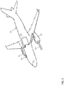
- the aircraft 10 includes one or more engines 12.
- the engines 12 intake air 14, which is compressed in a compressor (not shown).
- the compressed air is mixed with a fuel burning system (not shown) to generate thrust.
- the ECS 50 aims to perform air conditioning (heated output air and/or cooled output air to the flight deck, cabin, cargo compartments, and avionics bay, etc.), while also assisting in flight deck and cabin pressurization.
- the ECS 50 includes a bleed air system (not shown in FIG. 1 ), which utilizes the bleed air (e.g., high-pressure bleed air and low-pressure bleed air) to control temperatures of various areas of the aircraft 10 such as the cabin and/or flight decks, etc.
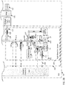
- the bleed air system 200 includes a left bleed air portion 202 which can receive bleed air from a left engine 12 and a right bleed air portion 204 which can receive bleed air from a right engine 12.
- the left and right bleed air portions 202 and 204 are controlled by an electronic ECS controller 150 in signal communication with an electronic air data computer (ADC) 152.
- the ADC 152 can operate to determine (e.g., calculate) ambient pressure (Pamb) and/or ambient temperature (Tamb) values.
- the controller 150 hereinafter referred to as the ECS controller 150 controls both bleed air portions 202 and 204.
- the bleed manifold 170 is has outlets 122, 124 which flow into the left bleed air portion 202 and right bleed air portion 204 respectively.
- the outlets 122, 124 of the bleed manifold 170 lead to the inlets 171, 172 of left PACK 114 and of right PACK 130 respectively.
- the bleed manifold 170 can also include a cross-bleed valve 18, which controls the supply of pre-cooled source air 109 (output from pre-coolers 109) to the left and right PACKs 114 and 130.
- the cross-bleed valve can be adjusted at any time (e.g., by a control signal) to control the pre-cooled source air 109 delivered to the left PACK 114 and the right PACK 130 via manifold outlets 122 and 124 respectively. In this manner, the bleed air system 200 can operate according to different modes as described in greater detail below.
- the left and right PACKs 114 and 130 are installed as separate and individual components. Each PACK 114 and 130 utilizes an air cycle machine which converts the pre-cooled air 109 into temperature-regulated air (heated air or cooled air).
- the PACKS 114 and 130 are also capable of measuring and controlling the mass flow of air using integrated mass air flow (MAF) sensors (not shown).
- Air output from the left and right PACKs 114 and 130, respectively, is delivered to a mixing and distribution unit 126 which can operate to mix air output from the PACKs 114 and 130, and with recirculated air from the cabin and flight deck.
- the mixed air can also be delivered to different zones of the aircraft 10, i.e., the flight deck 128 and the cabin 132.
- the remaining components of the left bleed air portion 202 and right bleed air portion 204 are mirror images of one another.
- the bleed air system 200 will be described in terms of the left bleed air portion 202 with the understanding the descriptions of the left air portion 202 can be applied to the right bleed air portion 204.
- the bleed air system 200 can operate in a 2S2P (two sources and two PACKs) mode, 1S2P (one source and two PACKs), IS IP (one source and one PACK), or a 2S1P (two sources and one PACK).
- 2S2P two sources and two PACKs
- 1S2P one source and two PACKs
- IS IP one source and one PACK
- 2S1P two sources and one PACK
- the cross bleed valve When operating in the 1S2P mode (e.g., during an ECS fault event), the cross bleed valve is opened and pre-cooled air 109 from either the left precooler 115 or the right precooler 115 is delivered to both left PACK 114 and the right PACK 130 via the bleed manifold 170.
- the cross bleed valve When operating in the 2S1P mode, the cross bleed valve is opened and pre-cooled air 109 from both the left precooler 115 and the right precooler 115 is delivered to either the left PACK 114 or the right PACK 130.
- the 2S1P mode may be invoked, for example, when one PACK has failed leaving a remaining pack to provide all the heating and cooling needs of the flight deck and cabin.
- the 2S1P mode can also be invoked when the aircraft is operating on the ground or with reduced passenger load and one PACK is turned off to improve fuel economy.
- the pre-cooler 115 operates according to either heated high-pressure bleed air 101 or low-pressure bleed air 103.
- a high-pressure bleed air network 102 ducting receives the high-pressure bleed air 101 from a high-pressure port bleed source (HPPB) 55
- a low-pressure bleed air network 104 ducting receives the low-pressure bleed air 103 from a low pressure port bleed source (LPPB) 57.
- An output duct 106 commonly connects the output of the high-pressure bleed air network 102 ducting and the output of the low-pressure bleed air network 104 ducting.
- the high-pressure bleed air network 102 further includes a high-pressure bleed air shutoff valve 110.
- the high-pressure bleed air shutoff valve 110 selectively controls the output of the high-pressure bleed air network 102 ducting and the output of the low-pressure bleed air network 104 ducting.
- the high-pressure bleed air shutoff valve 110 can be opened such that the high-pressure bleed air 101 is delivered through the airflow networks in 202 and 204.
- a check valve 111 installed in the low-pressure bleed air network 104 ducting is forced closed, thereby blocking the low-pressure bleed air 103 from flowing through the airflow networks in 202 and 204.
- the high-pressure bleed air shutoff valve 110 can be closed which in turn opens the check valve 111 to supply low-pressure bleed air 103. Accordingly, the low-pressure bleed air 103 flows through the airflow networks in 202 and 204.
- the airflow system 202 and 204 also includes a ram air system 108.
- the ram air system 108 generates cool air 105 (also known as a cold sink system) which can be used to cool the bleed air 101 or 103 delivered to the precooler 115. Heat from the high-pressure bleed air 101 or low-pressure bleed air 103 is then exchanged with the cool air 105.
- cool air 105 is converted into heated ram air 107.
- This heated ram air 107 is discharged into the atmosphere via an overboard port 112 so that it is prevented from entering the cabin.
- the ram air 105, 107 does not physically mix with the bleed air 106, 109; rather heat is exchanged only.
- the pre-cooled air output 109 from the precooler 115 can be regulated using a pressure regulating shutoff valve (PRSOV) 116, while the PACKS 114 and 130 are capable of measuring and controlling the mass flow of air. Accordingly, the mass flow rate of either the high-pressure bleed air 101 or the low-pressure bleed air 103 can be determined.
- the pressure measurements from sensors 118 allow the ECS controller 150 to regulate the bleed manifold pressure using the PRSOV 116, while using the ram air control valve 117 to regulate the bleed manifold temperature.
- the bleed manifold pressure sensor 118 and/or bleed manifold temperature sensor 120 can be located at different locations than illustrated in FIGS. 2A-2B without departing from the scope of the invention.
- the position of the PRSOV 116 (i.e., slave PRSOV 116) associated with the deactivated PACK can be adjusted to match the position of the PRSOV 116 (i.e., master PRSOV 116) associated with the activated PACK.
- the slave PRSOV 116 would have a "slaving" response and would track the position of the master PRSOV 116.
- the ECS controller 150 can generate a control signal that adjusts a position of the high-pressure bleed air shutoff valve 110, thereby selectively controlling delivery of the high-pressure bleed air 101 and low-pressure bleed air 103 to PACKs 114 and 130.
- the check valve 111 is automatically opened. Accordingly, high-pressure bleed air 101 is blocked from entering the output duct 106 while the low-pressure bleed air 103 is delivered to the output duct 106 and is ultimately used to provide bleed air to PACK 114.
- the check valve 111 is automatically closed.
- the low-pressure bleed air 103 is blocked from entering the output duct 106 while the high-pressure bleed air 101 is delivered to the output duct 106 and is ultimately used to provide bleed air to the PACK 114.
- the ECS controller 150 can detect conditions which allow usage of the low-pressure bleed air 103, and can adjust the valve 110 such that the low-pressure bleed air 103 is delivered from the output duct 106 to provide bleed air to the PACK 114.
- the ECS Controllers 150 command both left and right HPSOV 110 to the same position. If both left and right side do not need high pressure air, the HPSOVs 110 are both commanded to the closed position. If either the left side or right side do need high pressure air, the HPSOVs 110 are both commanded to the open position. When transitioning from HPSOVs ON to OFF or OFF to ON, it is important to close the cross-bleed valve 18 to prevent re-ingestion of hot cases from one engine to the other.
- the 2S1P flow sharing mode is active only if the PLA settings for left and right engine are relatively equal as read by left and right FADECs 155.
- the PLA readings 156 are transmitted from the FADECs to the ECS Controller 150 via a digital serial link such as ARINC-429. If the PLA readings 156 are not equal, the 2S1P mode is disabled and the cross-bleed valve 18 is closed resulting in IS IP mode. Should the PLA readings 156 become equal again, the ECS controller will enable 2S1P mode and open the cross-bleed valve 18.
- the bleed air system 200 can utilize the operation of the PRSOV 116 to balance the flow extraction between the left engine 12 and the right engine 12 without using additional air flow measurements and/or sensors. That is, the bleed air system allows the air flow rates from each engine 12 to remain relatively the same (e.g., 50 +/- 20% of the total flow) with respect to one another without measuring the output air flow from each engine 12.
- the flow difference between engines is due to numerous small tolerance variations which are not corrected for such as engine pressures for a given PLA position, slight PLA throttle stagger, tolerances in reading PLA by the FADEC 155, asymmetric ducting to the pack, etc. In this manner, a less expensive system and a more reliable ECS 50 is provided.
- the PRSOV 116 can regulate bleed manifold pressure to a fixed constant value such (e.g., as 35 PSIG), while the inlet pressure to PRSOV 116 is greater than the fixed pressure value.
- the fixed pressure value can therefore be used as target or reference pressure value (P Ref ).
- the PRSOV 116 outlet pressure is approximately 35 PSIG, regardless of whether high-pressure bleed air 101 or low-pressure bleed air 103 is used.
- a valve position sensor such as a rotary variable transformer (RVT) 125, for example, is also provided, which can measure the current position of the PRSOV 116.
- RVT rotary variable transformer
- the ECS controller 150 can execute a nested feedback control loop 300 to modulate (i.e., adjust) bleed manifold pressure using the PRSOV 116.
- an outer loop 302 provides a subtracted measured feedback of the pressure P FB using sensor 118 from the reference pressure P Ref and then subjects the error to a proportional and integral compensation.
- the output of the outer loop 302 is then a PRSOV position reference Pos Ref .
- This PRSOV position command Pos Ref becomes the reference or target value for an inner loop 304 on position.
- the inner loop 304 subtracts measured feedback of the position Pos FB of the PRSOV 116 from the reference Pos Ref and then subjects the error to a proportional and integral compensation.
- the output of the inner loop 304 is then a PRSOV position command Pos Cmd . Accordingly, the ECS controller 150 can continuously adjust the PRSOV 116 until the value of the feedback pressure signal (P FB ) output by pressure sensor 118 reaches the reference pressure value (P Ref ); e.g., 35 PSIG).
- P FB feedback pressure signal
- P Ref reference pressure value
- the bleed air system 200 is illustrated operating in the 2S1P mode.
- the left PACK (not shown in FIG. 4 ) is activated while the right PACK (not shown in FIG. 4 ) is deactivated
- the left PRSOV 116 would be modulated according to a master control loop 400 such that the bleed manifold pressure measured by left pressure sensor 118 is equal to P Ref (e.g., 35 PSIG), while the right PRSOV 116 acts as a slave (i.e., follows) to the left PRSOV 116.
- P Ref e.g. 35 PSIG
- the right PRSOV 116 is acting as a slave to the left PRSOV 116 (i.e., is following the left PRSOV 116)
- the right PRSOV 116 is also adjusted based on the results of an inner loop 304b portion of nested slave control loop 402 to match the position of the left PRSOV 116.
- Pos Ref from the left PRSOV Master Control Loop 400 is used to Pos Re f for the right PRSOV inner loop 304b.
- the right PRSOV 116 would be modulated according to a master control loop 400 such that the bleed manifold pressure measured by right pressure sensor 118 is equal to P Ref (e.g., 35 PSIG), while the left PRSOV 116 acts as a slave (i.e., follows) to the right PRSOV 116.
- P Ref e.g. 35 PSIG
- the left PRSOV 116 is acting as a slave to the right PRSOV 116 (i.e., is following the right PRSOV 116)
- the left PRSOV 116 is also adjusted based on the results of a nested slave control loop 402 to match the position of the right PRSOV 116.
- the proportional and integral gains for the pressure outer loop (302a/302b) are half the values of those used when the PRSOV operates normally (i.e., not in master/slave mode).
- an ECS that includes a nested feedback control loop that controls operation of the PRSOV 116 based on a comparison between the value of the feedback pressure signal (P FB ) output by pressure sensor 118 and a set target bleed manifold pressure value P Ref (e.g., 35 PSIG).
- P FB feedback pressure signal
- P Ref set target bleed manifold pressure value
Landscapes
- Engineering & Computer Science (AREA)
- General Health & Medical Sciences (AREA)
- Aviation & Aerospace Engineering (AREA)
- Pulmonology (AREA)
- Health & Medical Sciences (AREA)
- Automation & Control Theory (AREA)
- Physics & Mathematics (AREA)
- General Physics & Mathematics (AREA)
- Chemical & Material Sciences (AREA)
- Combustion & Propulsion (AREA)
- Mechanical Engineering (AREA)
- General Engineering & Computer Science (AREA)
- Fluid-Pressure Circuits (AREA)
- Control Of Fluid Pressure (AREA)
- Combined Controls Of Internal Combustion Engines (AREA)
Applications Claiming Priority (1)
| Application Number | Priority Date | Filing Date | Title |
|---|---|---|---|
| US15/927,568 US10926883B2 (en) | 2018-03-21 | 2018-03-21 | Environmental control system including shared air source with balanced airflow output |
Publications (1)
| Publication Number | Publication Date |
|---|---|
| EP3543134A1 true EP3543134A1 (de) | 2019-09-25 |
Family
ID=65817808
Family Applications (1)
| Application Number | Title | Priority Date | Filing Date |
|---|---|---|---|
| EP19162932.8A Withdrawn EP3543134A1 (de) | 2018-03-21 | 2019-03-14 | Umweltkontrollsystem mit gemeinsam verwendeter luftquelle mit ausgeglichenem luftstromausgang |
Country Status (2)
| Country | Link |
|---|---|
| US (1) | US10926883B2 (de) |
| EP (1) | EP3543134A1 (de) |
Cited By (1)
| Publication number | Priority date | Publication date | Assignee | Title |
|---|---|---|---|---|
| EP4102042A1 (de) * | 2021-06-07 | 2022-12-14 | Rohr, Inc. | Flugzeug-druckluftanlage mit zwei druckquellen und druckentlastung |
Families Citing this family (1)
| Publication number | Priority date | Publication date | Assignee | Title |
|---|---|---|---|---|
| US12298789B2 (en) * | 2020-11-06 | 2025-05-13 | Hamilton Sundstrand Corporation | Digitally augmented pneumatic control |
Citations (6)
| Publication number | Priority date | Publication date | Assignee | Title |
|---|---|---|---|---|
| EP0190943A2 (de) * | 1985-02-08 | 1986-08-13 | AlliedSignal Inc. | Ausgleichtechnik für die Abzapfluftablaufmenge aus den Flugzeugtriebwerken |
| DE69201452T2 (de) * | 1991-04-01 | 1995-06-14 | United Technologies Corp | Zapfluftdurchflussregulator mit Strömungsgleichgewicht. |
| WO2002048813A2 (en) * | 2000-12-14 | 2002-06-20 | Nor-Cal Products, Inc. | Improved pressure controller and method |
| US20090298407A1 (en) * | 2008-05-29 | 2009-12-03 | Honeywell International Inc. | Aircraft cabin pressure descent detection and control system and method |
| US20170137132A1 (en) * | 2015-11-16 | 2017-05-18 | Cessna Aircraft Company | Aircraft environmental control system providing improved performance and backup temperature control |
| US20180065752A1 (en) * | 2016-09-02 | 2018-03-08 | Embraer S.A. | Aircraft air conditioning system airflow regulation |
Family Cites Families (6)
| Publication number | Priority date | Publication date | Assignee | Title |
|---|---|---|---|---|
| US6494047B2 (en) | 2000-12-07 | 2002-12-17 | Honeywell International Inc. | Airflow sharing |
| GB0224625D0 (en) | 2002-10-23 | 2002-12-04 | Honeywell Normalair Garrett | Method of balancing the supply of bleed air from a plurality of engines |
| US6782701B2 (en) | 2003-01-22 | 2004-08-31 | Honeywell International Inc. | Master-slave engine bleed flow sharing control method and system |
| US7536865B2 (en) * | 2005-02-09 | 2009-05-26 | Honeywell International Inc. | Method and system for balancing bleed flows from gas turbine engines |
| US8033118B2 (en) * | 2008-01-31 | 2011-10-11 | EMBRAER—Empresa Brasileira de Aeronautica S.A. | Bleed airflow balancing control using simplified sensing |
| US11377216B2 (en) * | 2016-08-23 | 2022-07-05 | Ge Aviation Systems Llc | Advanced method and aircraft for pre-cooling an environmental control system using a dual compressor four wheel turbo-machine |
-
2018
- 2018-03-21 US US15/927,568 patent/US10926883B2/en active Active
-
2019
- 2019-03-14 EP EP19162932.8A patent/EP3543134A1/de not_active Withdrawn
Patent Citations (6)
| Publication number | Priority date | Publication date | Assignee | Title |
|---|---|---|---|---|
| EP0190943A2 (de) * | 1985-02-08 | 1986-08-13 | AlliedSignal Inc. | Ausgleichtechnik für die Abzapfluftablaufmenge aus den Flugzeugtriebwerken |
| DE69201452T2 (de) * | 1991-04-01 | 1995-06-14 | United Technologies Corp | Zapfluftdurchflussregulator mit Strömungsgleichgewicht. |
| WO2002048813A2 (en) * | 2000-12-14 | 2002-06-20 | Nor-Cal Products, Inc. | Improved pressure controller and method |
| US20090298407A1 (en) * | 2008-05-29 | 2009-12-03 | Honeywell International Inc. | Aircraft cabin pressure descent detection and control system and method |
| US20170137132A1 (en) * | 2015-11-16 | 2017-05-18 | Cessna Aircraft Company | Aircraft environmental control system providing improved performance and backup temperature control |
| US20180065752A1 (en) * | 2016-09-02 | 2018-03-08 | Embraer S.A. | Aircraft air conditioning system airflow regulation |
Cited By (1)
| Publication number | Priority date | Publication date | Assignee | Title |
|---|---|---|---|---|
| EP4102042A1 (de) * | 2021-06-07 | 2022-12-14 | Rohr, Inc. | Flugzeug-druckluftanlage mit zwei druckquellen und druckentlastung |
Also Published As
| Publication number | Publication date |
|---|---|
| US10926883B2 (en) | 2021-02-23 |
| US20190291872A1 (en) | 2019-09-26 |
Similar Documents
| Publication | Publication Date | Title |
|---|---|---|
| US5155991A (en) | Bleed air flow regulators with flow balance | |
| US8033118B2 (en) | Bleed airflow balancing control using simplified sensing | |
| US5511385A (en) | Independent compartment temperature control for single-pack operation | |
| US10011361B2 (en) | Aircraft environmental control system providing improved performance and backup temperature control | |
| EP0190943A2 (de) | Ausgleichtechnik für die Abzapfluftablaufmenge aus den Flugzeugtriebwerken | |
| EP1585666B1 (de) | Master-slave-motorzapfluftteilsteuerverfahren und -system | |
| US9321535B2 (en) | System and process for cooling an aircraft zone using an aircraft-external air assembly | |
| EP3543137B1 (de) | Zapflufttemperatur- und strömungssteuerungssystem | |
| US20120185116A1 (en) | Integrated bleed and engine controller | |
| US10926883B2 (en) | Environmental control system including shared air source with balanced airflow output | |
| EP3543136B1 (de) | Synthetisiertes niederdruck-zapfluftschema für ein flugzeugzapfluftnetzwerk | |
| US20020069646A1 (en) | Airflow sharing | |
| RU2375256C2 (ru) | Устройство и способ регулирования температуры в кабине воздушного судна | |
| US20230166846A1 (en) | Variable chiller exhaust with crown ventilation | |
| US8612063B2 (en) | Temperature control setpoint offset for ram air minimization | |
| EP0794898B1 (de) | Unabhängige temperaturkontrolle in verschiedenen raumeinheiten bei einer einzelklimaanlage | |
| EP3543148B1 (de) | Flugzeugklimaanlagensteuerungssystem mit ventildiagnose ohne positionsrückkopplung | |
| CN110471475B (zh) | 温度调节系统和由其实现的应用方法 | |
| US20170066536A1 (en) | Aircraft air conditioning system with a reduced process air demand | |
| SU304186A1 (ru) | Регулятор температуры воздуха в самолетных | |
| Lehle | Airbus A 330/340 environmental control system | |
| JPH03122427A (ja) | 航空機用空気調和装置 |
Legal Events
| Date | Code | Title | Description |
|---|---|---|---|
| PUAI | Public reference made under article 153(3) epc to a published international application that has entered the european phase |
Free format text: ORIGINAL CODE: 0009012 |
|
| STAA | Information on the status of an ep patent application or granted ep patent |
Free format text: STATUS: THE APPLICATION HAS BEEN PUBLISHED |
|
| AK | Designated contracting states |
Kind code of ref document: A1 Designated state(s): AL AT BE BG CH CY CZ DE DK EE ES FI FR GB GR HR HU IE IS IT LI LT LU LV MC MK MT NL NO PL PT RO RS SE SI SK SM TR |
|
| AX | Request for extension of the european patent |
Extension state: BA ME |
|
| STAA | Information on the status of an ep patent application or granted ep patent |
Free format text: STATUS: REQUEST FOR EXAMINATION WAS MADE |
|
| 17P | Request for examination filed |
Effective date: 20191216 |
|
| RBV | Designated contracting states (corrected) |
Designated state(s): AL AT BE BG CH CY CZ DE DK EE ES FI FR GB GR HR HU IE IS IT LI LT LU LV MC MK MT NL NO PL PT RO RS SE SI SK SM TR |
|
| STAA | Information on the status of an ep patent application or granted ep patent |
Free format text: STATUS: EXAMINATION IS IN PROGRESS |
|
| 17Q | First examination report despatched |
Effective date: 20200911 |
|
| GRAP | Despatch of communication of intention to grant a patent |
Free format text: ORIGINAL CODE: EPIDOSNIGR1 |
|
| STAA | Information on the status of an ep patent application or granted ep patent |
Free format text: STATUS: GRANT OF PATENT IS INTENDED |
|
| INTG | Intention to grant announced |
Effective date: 20241119 |
|
| RIC1 | Information provided on ipc code assigned before grant |
Ipc: G05D 16/20 20060101ALN20241112BHEP Ipc: G05D 7/06 20060101ALI20241112BHEP Ipc: B64D 13/06 20060101AFI20241112BHEP |
|
| STAA | Information on the status of an ep patent application or granted ep patent |
Free format text: STATUS: THE APPLICATION IS DEEMED TO BE WITHDRAWN |
|
| 18D | Application deemed to be withdrawn |
Effective date: 20250320 |