EP3543162B1 - Behälterausgiesser für einen nachfüllbehälter - Google Patents
Behälterausgiesser für einen nachfüllbehälter Download PDFInfo
- Publication number
- EP3543162B1 EP3543162B1 EP17877634.0A EP17877634A EP3543162B1 EP 3543162 B1 EP3543162 B1 EP 3543162B1 EP 17877634 A EP17877634 A EP 17877634A EP 3543162 B1 EP3543162 B1 EP 3543162B1
- Authority
- EP
- European Patent Office
- Prior art keywords
- pouring
- spout
- closing member
- pouring spout
- container
- Prior art date
- Legal status (The legal status is an assumption and is not a legal conclusion. Google has not performed a legal analysis and makes no representation as to the accuracy of the status listed.)
- Active
Links
Images



Classifications
-
- B—PERFORMING OPERATIONS; TRANSPORTING
- B65—CONVEYING; PACKING; STORING; HANDLING THIN OR FILAMENTARY MATERIAL
- B65D—CONTAINERS FOR STORAGE OR TRANSPORT OF ARTICLES OR MATERIALS, e.g. BAGS, BARRELS, BOTTLES, BOXES, CANS, CARTONS, CRATES, DRUMS, JARS, TANKS, HOPPERS, FORWARDING CONTAINERS; ACCESSORIES, CLOSURES, OR FITTINGS THEREFOR; PACKAGING ELEMENTS; PACKAGES
- B65D47/00—Closures with filling and discharging, or with discharging, devices
- B65D47/04—Closures with discharging devices other than pumps
- B65D47/06—Closures with discharging devices other than pumps with pouring spouts or tubes; with discharge nozzles or passages
-
- B—PERFORMING OPERATIONS; TRANSPORTING
- B65—CONVEYING; PACKING; STORING; HANDLING THIN OR FILAMENTARY MATERIAL
- B65D—CONTAINERS FOR STORAGE OR TRANSPORT OF ARTICLES OR MATERIALS, e.g. BAGS, BARRELS, BOTTLES, BOXES, CANS, CARTONS, CRATES, DRUMS, JARS, TANKS, HOPPERS, FORWARDING CONTAINERS; ACCESSORIES, CLOSURES, OR FITTINGS THEREFOR; PACKAGING ELEMENTS; PACKAGES
- B65D47/00—Closures with filling and discharging, or with discharging, devices
- B65D47/04—Closures with discharging devices other than pumps
- B65D47/06—Closures with discharging devices other than pumps with pouring spouts or tubes; with discharge nozzles or passages
- B65D47/08—Closures with discharging devices other than pumps with pouring spouts or tubes; with discharge nozzles or passages having articulated or hinged closures
-
- B—PERFORMING OPERATIONS; TRANSPORTING
- B65—CONVEYING; PACKING; STORING; HANDLING THIN OR FILAMENTARY MATERIAL
- B65D—CONTAINERS FOR STORAGE OR TRANSPORT OF ARTICLES OR MATERIALS, e.g. BAGS, BARRELS, BOTTLES, BOXES, CANS, CARTONS, CRATES, DRUMS, JARS, TANKS, HOPPERS, FORWARDING CONTAINERS; ACCESSORIES, CLOSURES, OR FITTINGS THEREFOR; PACKAGING ELEMENTS; PACKAGES
- B65D47/00—Closures with filling and discharging, or with discharging, devices
- B65D47/04—Closures with discharging devices other than pumps
- B65D47/06—Closures with discharging devices other than pumps with pouring spouts or tubes; with discharge nozzles or passages
- B65D47/08—Closures with discharging devices other than pumps with pouring spouts or tubes; with discharge nozzles or passages having articulated or hinged closures
- B65D47/0804—Closures with discharging devices other than pumps with pouring spouts or tubes; with discharge nozzles or passages having articulated or hinged closures integrally formed with the base element provided with the spout or discharge passage
-
- B—PERFORMING OPERATIONS; TRANSPORTING
- B65—CONVEYING; PACKING; STORING; HANDLING THIN OR FILAMENTARY MATERIAL
- B65D—CONTAINERS FOR STORAGE OR TRANSPORT OF ARTICLES OR MATERIALS, e.g. BAGS, BARRELS, BOTTLES, BOXES, CANS, CARTONS, CRATES, DRUMS, JARS, TANKS, HOPPERS, FORWARDING CONTAINERS; ACCESSORIES, CLOSURES, OR FITTINGS THEREFOR; PACKAGING ELEMENTS; PACKAGES
- B65D75/00—Packages comprising articles or materials partially or wholly enclosed in strips, sheets, blanks, tubes or webs of flexible sheet material, e.g. in folded wrappers
- B65D75/52—Details
- B65D75/58—Opening or contents-removing devices added or incorporated during package manufacture
-
- B—PERFORMING OPERATIONS; TRANSPORTING
- B65—CONVEYING; PACKING; STORING; HANDLING THIN OR FILAMENTARY MATERIAL
- B65D—CONTAINERS FOR STORAGE OR TRANSPORT OF ARTICLES OR MATERIALS, e.g. BAGS, BARRELS, BOTTLES, BOXES, CANS, CARTONS, CRATES, DRUMS, JARS, TANKS, HOPPERS, FORWARDING CONTAINERS; ACCESSORIES, CLOSURES, OR FITTINGS THEREFOR; PACKAGING ELEMENTS; PACKAGES
- B65D75/00—Packages comprising articles or materials partially or wholly enclosed in strips, sheets, blanks, tubes or webs of flexible sheet material, e.g. in folded wrappers
- B65D75/52—Details
- B65D75/58—Opening or contents-removing devices added or incorporated during package manufacture
- B65D75/5861—Spouts
- B65D75/5872—Non-integral spouts
-
- B—PERFORMING OPERATIONS; TRANSPORTING
- B65—CONVEYING; PACKING; STORING; HANDLING THIN OR FILAMENTARY MATERIAL
- B65D—CONTAINERS FOR STORAGE OR TRANSPORT OF ARTICLES OR MATERIALS, e.g. BAGS, BARRELS, BOTTLES, BOXES, CANS, CARTONS, CRATES, DRUMS, JARS, TANKS, HOPPERS, FORWARDING CONTAINERS; ACCESSORIES, CLOSURES, OR FITTINGS THEREFOR; PACKAGING ELEMENTS; PACKAGES
- B65D75/00—Packages comprising articles or materials partially or wholly enclosed in strips, sheets, blanks, tubes or webs of flexible sheet material, e.g. in folded wrappers
- B65D75/52—Details
- B65D75/58—Opening or contents-removing devices added or incorporated during package manufacture
- B65D75/5861—Spouts
- B65D75/5872—Non-integral spouts
- B65D75/5883—Non-integral spouts connected to the package at the sealed junction of two package walls
Definitions
- the present invention relates to a pouring spout for a refill container storing contents for refilling a packaging container with the contents.
- Liquid seasoning such as soy sauce and toiletry products such as liquid detergents are, for example, stored in a packaging container made of a resin and consumed. Once a residual amount of the contents is decreased or depleted, the packaging container is refilled with the contents and the product is further used. With such products, a refilling container storing the contents for refilling is prepared separately from the packaging container. As the refilling container, various types have been proposed.
- the pouring nozzle when the pouring nozzle constituting the pouring unit of the packaging container is inserted into an interior of the pouring spout of the refilling container, the pouring nozzle breaks the sealing plate at the position of the weak line described above, separating the planned opening part, which is a region on the inner side, from the sealing plate. With the sealing plate separated, the refill container is configured to allow transfer of the contents filled in the interior of the refill container to the packaging container to refill the packaging container with the contents.
- JP2014129141A discloses a spout for a refill container according to the preamble of claim 1.
- EP2110332A1 discloses a press-open type storage device with a prestressed to open closure, wherein a relative stable state relationship of the closure and one side of the storage device being connectedly attached by a flexible flake type structure is characterized in that when the closure is closed relative to the storage device, the connecting flake type structure is bent to appear in a prestressed status to an opening direction thereby keeping the closure to remain at a stable opening status after it is pressed to open.
- Patent Document 1 Japanese Laid-Open Patent Application No. 2013-203464
- the planned opening part is formed by forming a weak part in the sealing plate provided to the spout. That is, in the sealing plate, an inner side and an outer side of the weak part is configured by a single member.
- the sealing part may not allow the planned opening part to smoothly separate at the position of the weak part.
- the pouring nozzle of the packaging container locally breaks through the sealing plate, forming a hole in the sealing plate.
- the pouring nozzle of the packaging container locally breaks through the sealing plate, forming a hole in the sealing plate, broken pieces of the sealing plate may be produced. When broken pieces are produced, the broken pieces may enter the packaging container and clog the pouring nozzle of the packaging container.
- a pouring spout for a refill container according to the present invention for solving the above-described problems is as specified in claim 1.
- the closing member is connected by a coupling member to the spout main body.
- the closing member is connected by the coupling member to the spout main body, making it possible to keep the closing member coupled without separation from the spout main body when the closing member is removed from the inner side of the tubular pouring part.
- the closing member is never moved to the packaging container.
- the closing member, the coupling member, and the spout main body may be configured as an integrated object made of a same material.
- Configuring the closing member, the coupling member, and the spout main body as an integrated object made of the same material makes it possible to integrally mold these using a manufacturing method such as injection molding. Thus, mass production of pouring spouts having identical quality is possible.
- the pouring spout according to the present invention may optionally be as specified in claim 3.
- a closing member that closes a tubular pouring part of a pouring spout from a spout main body of the pouring spout and communicate a channel formed in the tubular pouring part of the pouring spout without producing broken pieces or the like.
- a pouring spout 10 for a refill container according to the present invention is as specified in claim 1.
- the pouring spout 10 for a refill container exhibits the particular effect of making it possible to separate the closing member 20 serving as a component that closes the tubular pouring part 11 of the pouring spout 10 from the spout main body 10A of the pouring spout 10, and communicate a channel 10b formed in the tubular pouring part 11 of the pouring spout 10, without producing broken pieces or the like.
- the following describes an overview of a container provided with the pouring spout 10, a specific configuration of the pouring spout 10, an overview of a packaging container 30 used after being refilled with contents stored in the container, and the action of the pouring spout 10.
- the pouring spout 10 comprises the spout main body 10A, the closing member 20, and a coupling member 21 is described.
- packaging container refers to a container refilled with contents
- container refers to a container used as a refilling container or the like storing contents for refilling the packaging container with contents and provided with the pouring spout according to the present invention.
- the container provided with the pouring spout 10 according to the present invention is mainly used as a refilling container for refilling the packaging container 30 used separately from this container with contents.
- the forms and types of the refilling container are not particularly limited.
- Fig. 1 shows a standing pouch 1 as an example of a refilling container.
- This standing pouch 1 comprises a pair of flat surface parts 2 facing each other, a bottom surface part 3 that closes a bottom part of the refilling container, and the pouring spout 10 according to the present invention.
- the flat surface parts 2 are sealed together at an upper edge, and sealed together at both side edges. Lower edges of the pair of flat surface parts 2 are each sealed at an edge part of the bottom surface part 3 facing the lower edge of the flat surface part 2.
- the bottom surface part 3 is folded in half at a crease 4 at a center thereof, and the crease 4 is folded toward an upper side of the standing pouch 1.
- the bottom surface part 3 is configured to allow a bottom part of the standing pouch 1 to be unfolded by the unfolding of the bottom surface part 3 from the folded state in the directions in which the flat surface parts 2 of the standing pouch 1 are arranged.
- the pouring spout 10 is attached to an upper edge of the standing pouch 1.
- the pouring spout 10 is configured by the spout main body 10A and a cap 19 that freely opens and closes the spout main body 10A.
- a case where the pouring spout 10 is attached to a middle of an upper part of the standing pouch 1 is given as an example.
- the pouring spout 10 may be provided in a position shifted to a side part in a width direction in the upper part of the standing pouch 1.
- the standing pouch 1 may be provided with an area communicated by an inclined part where the upper edge and the side edge are obliquely inclined, and the pouring spout 10 may be attached to the inclined part.
- the standing pouch 1 is used as a refilling container for transferring the contents into the packaging container 30 (refer to Fig. 4 ) prepared separately from the standing pouch 1.
- the cap 19 that closes the pouring spout 10 is removed, and the standing pouch 1 is turned upside down. Then, the pouring spout 10 is inserted into a pouring unit 40 of the packaging container 30, and the contents are transferred directly from the standing pouch 1 into the packaging container 30. Note that this action is described in detail later.
- a thread part 12 is formed on an outer circumferential surface of the tubular pouring part 11.
- the thread part 12 extends in a circumferential direction, shifts position in the axial direction L, and has a spiral shape.
- This thread part 12 is an area that engages with a thread part (not illustrated) formed on an inner surface of the cap 19.
- the tubular pouring part 11 is configured so that, with the thread part of the cap 19 engaged with the thread part 12, the other end B side of the tubular pouring part 11 is closed and opened.
- the attached part 15 has a so-called boat shape.
- a boat shape refers to a shape in which side surface parts 16 of the attached part 15 on both sides in a horizontal direction (direction denoted by reference sign Y in Fig. 3 ) protrude toward the outer sides, and have acute angles that come to a point on both sides in a vertical direction (direction denoted by reference sign X in Fig. 3 ). Heights of the side surface parts 16 are uniformly formed.
- Each of the side surface parts 16 is configured by an inclined surface part 16a that inclines from a center toward the outer side in the Y direction, from both ends in the X direction toward the middle, and a curved part 16b that protrudes toward the outer sides in the Y direction in a center portion in the X direction.
- the curved part 16b as illustrated in Fig. 3 , has an arc shape when the pouring spout 10 is viewed from the one end A side.
- a plurality of protruding parts 17 extending in the vertical direction are formed on each of the side surface parts 16, as illustrated in Fig. 2 .
- a hole 10c that passes through this side surface part 16 in a height direction is formed in a center of the attached part 15. This hole 10c partially constitutes the channel 10b formed in the interior of the tubular pouring part 11.
- a flange 18 protruding toward the outer side in a radial direction is formed in a boundary portion between the tubular pouring part 11 and the attached part 15.
- This flange 18 is an area extending along the upper edge of the standing pouch 1 when the pouring spout 10 is attached to the upper end of the standing pouch 1.
- the closing member 20 is a component for closing the channel 10b of the pouring spout 10, and is configured as a separate body from the spout main body 10A.
- This closing member 20 has a disk shape.
- the closing member 20 closes the channel 10b of the pouring spout 10 by being fit onto the inner side of the channel 10b of the pouring spout 10 on the one end A side of the tubular pouring part 11 in the axial direction L, that is, on the attached part 15 side.
- the closing member 20 that closes the channel 10b of the pouring spout 10 is configured so that the closing member 20 is removed by an external force applied from the other end B side opposite to the one end A side of the tubular pouring part 11 in the axial direction L from the inner circumferential surface of the tubular pouring part 11.
- a diameter of the closing member 20 is formed to the same size as or slightly smaller than an inner diameter of the channel 10b of the pouring spout 10.
- the closing member 20 is connected to the spout main body 10A by the coupling member 21.
- the coupling member 21 is made of a resin, and has a long, narrow string shape. Alternatively, this coupling member 21 can be formed into a strip shape as well. That is, the closing member 20 is connected by the coupling member 21 having a string shape or a strip shape to the spout main body 10A.
- One end of the coupling member 21 in the longitudinal direction is coupled to an end surface of the spout main body 10A on the one end A side. Specifically, one end of the coupling member 21 in the longitudinal direction is coupled to a lower end surface of the attached part 15.
- This one end is coupled to the lower end surface of the attached part 15 at a position slightly shifted to the outer side in a radial direction from the peripheral part of the channel 10b.
- the other end of the coupling member 21 in the longitudinal direction is coupled to a lower surface 20b of the closing member 20. That is, the coupling member 21 couples the lower surface 20b of the closing member 20, which is a surface facing the lower side in a mode of being fitted into the channel 10b, and the attached part 15.
- an upper surface 20a of the closing member 20 is a surface facing the upper side in a mode in which the closing member 20 is fitted into the channel 10b of the pouring spout 10. That is, the upper surface 20a of the closing member 20 is a surface facing the other end B side of the tubular pouring part 11 in the axial direction L in a mode in which the closing member 20 is fitted into the channel 10b of the pouring spout 10.
- the lower surface 20b of the closing member 20 is a surface facing the lower side in a mode in which the closing member 20 is fitted into the channel 10b of the pouring spout 10.
- the lower surface of the closing member 20 is a surface facing the interior of the container (standing pouch 1) to which the pouring spout 10 is attached in a mode in which the closing member 20 is fitted into the channel 10b of the pouring spout 10.
- the coupling member 21 couples the closing member 20 and the spout main body 10A in such a manner that a force is applied in a direction in which the closing member 20 is separated from the channel 10b of the pouring spout 10.
- Both ends of the coupling member 21 couple the spout main body 10A and the closing member 20 as described above, and thus the closing member 20 is fitted onto the inner side of the channel 10b without the coupling member 21 getting pinched between the closing member 20 and the channel 10b. Further, when the closing member 20 is removed from the inner side of the channel 10b, the closing member 20 is maintained in a state of connection to the pouring spout 10 without being separated from the spout main body 10A.
- the packaging container 30 is a container used after being refilled with contents stored in the standing pouch 1.
- the packaging container 30 is made of a resin or the like, for example.
- Fig. 4 shows an example of the packaging container 30.
- the packaging container 30 illustrated in Fig. 4 is configured by a container main body 31 provided with a handle 32, and the pouring unit 40 for pouring the contents stored in the container main body 31.
- This packaging container 30 is used by removing from the packaging container 30 the contents moved from the standing pouch 1 in an amount required when necessary.
- the nozzle 43 is disposed in a middle or substantial middle position of the main body part 41.
- the nozzle 43 is connected to the peripheral wall surface 42, and is integrated with the peripheral wall surface 42.
- the nozzle 43 is configured to protrude toward an upper side of the main body part 41, with a tip end thereof positioned on an upper side of the upper end of the peripheral wall surface 42.
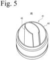
- Fig. 5 shows one example of the shape of the nozzle 43, and the shape of the nozzle 43 is not particularly limited.
- the pouring spout 10 can be manufactured by various manufacturing methods. However, when manufacturing efficiency, manufacturing cost, and quality are considered, the spout main body 10A, the closing member 20, and the coupling member 21 are preferably integrally molded by injection-molding a resin.
- the manufacturing method for injection-molding a resin allows the spout main body 10A, the closing member 20, and the coupling member 21 to be integrally molded using the same material, making it possible to increase the manufacturing efficiency and keep the manufacturing cost to a low level. Further, once a die is manufactured, products having the identical quality can be repeatedly manufactured.
- the procedure for refilling the packaging container 30 with the contents stored in the standing pouch 1, and the action of the pouring spout 10 of the present embodiment will now be described with reference to Fig. 6 .
- the standing pouch 1 and the container main body 31 of the packaging container 30 are not illustrated in Fig. 6 .
- the pouring spout 10 is attached to the standing pouch 1, which is a refilling container, illustrated in Fig. 1
- the pouring unit 40 is provided to the packaging container 30 illustrated in Fig. 4 .
- the cap 19 is removed from the pouring spout 10, the standing pouch 1 is turned upside down, and the pouring spout 10 is positioned on a lower side of the standing pouch 1.
- the channel 10b of the pouring spout 10 is closed by the closing member 20, and thus the contents stored in the standing pouch 1 never spill out.
- the pouring spout 10 is matched with the position of the pouring unit 40 of the packaging container 30 from which the cap 19 is removed, and the nozzle 43 of the pouring unit 40 is inserted into the channel 10b of the pouring spout 10. That is, the nozzle 43 of the pouring unit 40 is inserted into the channel 10b configured on the inner side of the tubular pouring part 11 constituting the pouring spout 10.
- the nozzle 43 is inserted into the interior of the tubular pouring part 11 and, when the closing member 20 is removed from the spout main body 10A, a tip end part 11a of the tubular pouring part 11 comes into contact with an outer circumferential surface of the nozzle. That is, in a mode in which the nozzle 43 is inserted into the tubular pouring part 11, the tip end of the tubular pouring part 11 is formed to a size resulting in contact with the outer circumferential surface of a base portion of the nozzle 43.
- the contents poured from the refill container 1 (standing pouch) are moved to the packaging container 30 through the nozzle 43 without leaking to the outer side of the nozzle 43.
Landscapes
- Engineering & Computer Science (AREA)
- Mechanical Engineering (AREA)
- Bag Frames (AREA)
- Closures For Containers (AREA)
- Details Of Rigid Or Semi-Rigid Containers (AREA)
- Cartons (AREA)
Claims (3)
- Ausgießtülle (10) für einen Wiederauffüllbehälter (1), in dem ein Inhalt zum Wiederauffüllen des Inhalts eines Verpackungsbehälters (30) gespeichert ist, wobei die Ausgießtülle (10) Folgendes umfasst:einen rohrförmigen Ausgießteil (11);einen befestigten Teil (15), der an dem Wiederauffüllbehälter (1) an einer Endseite des rohrförmigen Ausgießteils (11) in axialer Richtung befestigbar ist; undein Verschlusselement (20) zum Verschließen der einen Endseite des rohrförmigen Ausgießteils (11), das als ein von einem Tüllenhauptkörper (10A) der Ausgießtülle (10) separater Körper ausgelegt ist und auf einer Innenumfangsfläche des rohrförmigen Ausgießteils (11) auf der einen Endseite davon derart befestigt ist, dass das Verschlusselement (20) durch eine externe Kraft, die von der zu der einen Endseite entgegengesetzten, anderen Endseite in axialer Richtung beaufschlagt wird, von der Innenumfangsfläche des rohrförmigen Ausgießteils (11) entfernt wird;dadurch gekennzeichnet, dass:das Verschlusselement (20) durch ein Kopplungselement (21) mit dem Tüllenhauptkörper (10A) verbunden ist;das Kopplungselement (21) aus einem Harz besteht und eine Bandform oder Streifenform aufweist, wobei ein Ende des Kopplungselements (21) in der Längsrichtung mit einer unteren Endfläche des befestigten Teils (15) des Tüllenhauptkörpers (10A) an einer Position gekoppelt ist, die in einer radialen Richtung von einem Umfangsteil eines Kanals (10b) der Ausgießtülle (10) leicht zur Außenseite versetzt ist;das andere Ende des Kopplungselements (21) in der Längsrichtung mit einer unteren Fläche (20b) des Verschlusselements (20) gekoppelt ist, welche eine Fläche des Verschlusselements (20) ist, die angeordnet ist, um einem Inneren des Wiederauffüllbehälters (1) zugewandt zu sein, wenn die Ausgießtülle (10) in einem Modus, in dem das Verschlusselement (20) in dem Kanal (10b) der Ausgießtülle (10) befestigt ist, an dem Wiederauffüllbehälter (1) angebracht wird;das Kopplungselement (21) das Verschlusselement (20) und den befestigten Teil (15) des Tüllenhauptkörpers (10A) derart koppelt, dass eine Kraft in einer Richtung, in der das Verschlusselement (20) vom Kanal (10b) der Ausgießtülle (10) getrennt wird, beaufschlagt wird.
- Ausgießtülle (10) nach Anspruch 1, wobei
das Verschlusselement (20), das Kopplungselement (21) und der Tüllenhauptkörper (10A) als ein einstückiger Gegenstand ausgelegt sind, der aus demselben Material besteht. - Ausgießtülle (10) nach Anspruch 1, wobei
das Verschlusselement (20) horizontal auf der Innenumfangsfläche des rohrförmigen Ausgießteils (11) auf der einen Endseite davon befestigt ist.
Applications Claiming Priority (2)
| Application Number | Priority Date | Filing Date | Title |
|---|---|---|---|
| JP2016238187A JP6960731B2 (ja) | 2016-12-08 | 2016-12-08 | 容器の注出用スパウト |
| PCT/JP2017/043944 WO2018105686A1 (ja) | 2016-12-08 | 2017-12-07 | 容器の注出用スパウト |
Publications (3)
| Publication Number | Publication Date |
|---|---|
| EP3543162A1 EP3543162A1 (de) | 2019-09-25 |
| EP3543162A4 EP3543162A4 (de) | 2019-12-11 |
| EP3543162B1 true EP3543162B1 (de) | 2025-07-09 |
Family
ID=62492003
Family Applications (1)
| Application Number | Title | Priority Date | Filing Date |
|---|---|---|---|
| EP17877634.0A Active EP3543162B1 (de) | 2016-12-08 | 2017-12-07 | Behälterausgiesser für einen nachfüllbehälter |
Country Status (8)
| Country | Link |
|---|---|
| US (1) | US10961025B2 (de) |
| EP (1) | EP3543162B1 (de) |
| JP (1) | JP6960731B2 (de) |
| KR (1) | KR20190094162A (de) |
| CN (1) | CN110062737B (de) |
| MY (1) | MY200018A (de) |
| PH (1) | PH12019501240A1 (de) |
| WO (1) | WO2018105686A1 (de) |
Families Citing this family (4)
| Publication number | Priority date | Publication date | Assignee | Title |
|---|---|---|---|---|
| JP7174593B2 (ja) * | 2018-10-30 | 2022-11-17 | 藤森工業株式会社 | 注出スパウト及び詰め替え容器から包装容器への内容物補充方法 |
| JP7193305B2 (ja) * | 2018-10-30 | 2022-12-20 | 藤森工業株式会社 | 注出スパウト |
| JP7251965B2 (ja) * | 2018-12-19 | 2023-04-04 | 藤森工業株式会社 | 注出口付き包装袋、およびその製造方法 |
| JP7251964B2 (ja) * | 2018-12-19 | 2023-04-04 | 藤森工業株式会社 | 注出口付き包装袋、およびその製造方法 |
Family Cites Families (37)
| Publication number | Priority date | Publication date | Assignee | Title |
|---|---|---|---|---|
| US1241352A (en) * | 1915-02-23 | 1917-09-25 | Charles Doering Jr | Water-dispensing device. |
| US3347410A (en) * | 1966-08-31 | 1967-10-17 | Schwartzman Gilbert | Mixing assemblies for applicators |
| IT994127B (it) * | 1973-08-03 | 1975-10-20 | Sigma Tau Ind Farmaceuti | Dispositivo per la chiusura ermetica di contenitori dotato di perforatore e di goccimetro |
| US4195730A (en) * | 1978-06-20 | 1980-04-01 | General Foods Corporation | Container having separate storage facilities for two materials |
| US4375864A (en) * | 1980-07-21 | 1983-03-08 | Scholle Corporation | Container for holding and dispensing fluid |
| US4371015A (en) * | 1980-12-24 | 1983-02-01 | Tbs, Inc. | Toner loading system having cartridge with displaceable diaphragm |
| US4445551A (en) * | 1981-11-09 | 1984-05-01 | Bond Curtis J | Quick-disconnect coupling and valve assembly |
| US4614437A (en) * | 1984-11-02 | 1986-09-30 | Dougherty Brothers Company | Mixing container and adapter |
| US5041267A (en) * | 1986-12-30 | 1991-08-20 | Air Products And Chemicals, Inc. | Ultra high purity reagent container with large breakseal |
| US5533553A (en) * | 1994-01-26 | 1996-07-09 | Colgate-Palmolive Co. | Container set comprising at least two containers |
| US5735320A (en) * | 1996-08-21 | 1998-04-07 | The Sherwin-Williams Company | Dispenser for a two-part composition |
| NL1006636C2 (nl) * | 1997-07-21 | 1999-01-25 | Itsac Nv | Verbindingssamenstel voor een fluïdumverbinding. |
| NL1011960C2 (nl) * | 1999-05-04 | 2000-11-07 | Itsac Nv | Houder, in het bijzonder een flexibele houder, met een afsluitbare opening en werkwijze voor het vullen van een dergelijke houder. |
| NL1016292C2 (nl) * | 2000-09-28 | 2002-04-02 | Itsac Nv | Zak alsmede een afgiftesysteem omvattende een dergelijke zak en werkwijzen voor de vervaardiging en het vullen van een dergelijke zak. |
| JP2003165560A (ja) * | 2001-11-30 | 2003-06-10 | Yoshino Kogyosho Co Ltd | 注出容器の開閉自在な弁体 |
| EP1676784A1 (de) * | 2004-12-29 | 2006-07-05 | The Procter & Gamble Company | Flexibler Flüssigkeitsbehälter, Verfahren zur Herstellung eines flüssigkeitsgefüllten Behälters |
| US7635012B2 (en) * | 2006-06-12 | 2009-12-22 | Jpro Dairy International, Inc. | Sealed storage container with a coupling assembly |
| DE102008012973B3 (de) * | 2008-03-06 | 2009-04-02 | Henkel Ag & Co. Kgaa | System zum Nachfüllen von fließ- oder schüttfähigen Wasch- oder Reinigungsmitteln |
| US8590700B2 (en) * | 2008-04-17 | 2013-11-26 | Tai-Her Yang | Sleeved to press-open type storage device with a prestressed to open closure |
| CN101570257B (zh) * | 2008-04-17 | 2014-09-17 | 杨泰和 | 封盖具掀开预力的受压开启型储存装置 |
| JP5207312B2 (ja) * | 2009-04-30 | 2013-06-12 | 株式会社吉野工業所 | 詰め替え容器 |
| JP5424148B2 (ja) * | 2009-06-30 | 2014-02-26 | 株式会社吉野工業所 | 継続使用容器と詰め替え容器の組合せ |
| US8910673B2 (en) * | 2009-12-25 | 2014-12-16 | Yoshino Kogyosho Co., Ltd. | Synthetic resin bottle, and a combination of regularly used container and refill container |
| JP5357099B2 (ja) * | 2010-03-31 | 2013-12-04 | 株式会社吉野工業所 | 注出栓及びそれを備える容器 |
| JP5523899B2 (ja) * | 2010-03-31 | 2014-06-18 | 株式会社吉野工業所 | 詰替え用ノズル |
| US20130319970A1 (en) * | 2010-12-27 | 2013-12-05 | Kao Corporation | Package |
| JP5744681B2 (ja) * | 2011-08-30 | 2015-07-08 | 株式会社吉野工業所 | 注出キャップ |
| JP5944662B2 (ja) * | 2011-12-28 | 2016-07-05 | 花王株式会社 | 詰め替え用注出キャップ |
| WO2013099978A1 (ja) * | 2011-12-28 | 2013-07-04 | 花王株式会社 | 詰替え容器用栓部材 |
| JP2013203464A (ja) | 2012-03-29 | 2013-10-07 | Toppan Printing Co Ltd | 詰め替え容器 |
| JP6183847B2 (ja) * | 2012-11-30 | 2017-08-23 | 花王株式会社 | 詰替え容器用栓体 |
| WO2014084264A1 (ja) * | 2012-11-30 | 2014-06-05 | 花王株式会社 | 詰替え容器用栓体 |
| CN104870334B (zh) * | 2012-12-28 | 2017-06-23 | 株式会社高丝 | 再充填容器用注出结构 |
| US10138448B2 (en) * | 2016-04-11 | 2018-11-27 | Veltek Associates, Inc | Deactivation wipe kit |
| JP6236139B1 (ja) * | 2016-12-08 | 2017-11-22 | 藤森工業株式会社 | 詰め替え容器の注出用スパウト及び包装容器の注出ユニットとの連結構造 |
| JP6194132B1 (ja) * | 2017-03-21 | 2017-09-06 | 藤森工業株式会社 | 容器の注出用スパウト |
| US10661968B1 (en) * | 2019-06-20 | 2020-05-26 | Elc Management Llc | Container system for mixing and dispensing |
-
2016
- 2016-12-08 JP JP2016238187A patent/JP6960731B2/ja active Active
-
2017
- 2017-12-07 US US16/466,933 patent/US10961025B2/en active Active
- 2017-12-07 CN CN201780074791.4A patent/CN110062737B/zh active Active
- 2017-12-07 EP EP17877634.0A patent/EP3543162B1/de active Active
- 2017-12-07 WO PCT/JP2017/043944 patent/WO2018105686A1/ja not_active Ceased
- 2017-12-07 KR KR1020197016142A patent/KR20190094162A/ko not_active Ceased
- 2017-12-07 MY MYPI2019003173A patent/MY200018A/en unknown
-
2019
- 2019-06-04 PH PH12019501240A patent/PH12019501240A1/en unknown
Also Published As
| Publication number | Publication date |
|---|---|
| US10961025B2 (en) | 2021-03-30 |
| CN110062737A (zh) | 2019-07-26 |
| EP3543162A1 (de) | 2019-09-25 |
| WO2018105686A1 (ja) | 2018-06-14 |
| CN110062737B (zh) | 2022-04-12 |
| PH12019501240A1 (en) | 2020-03-02 |
| JP2018095258A (ja) | 2018-06-21 |
| US20200062463A1 (en) | 2020-02-27 |
| MY200018A (en) | 2023-12-04 |
| KR20190094162A (ko) | 2019-08-12 |
| EP3543162A4 (de) | 2019-12-11 |
| JP6960731B2 (ja) | 2021-11-05 |
Similar Documents
| Publication | Publication Date | Title |
|---|---|---|
| EP3543165B1 (de) | Verbindungsstruktur zwischen der ausgiesstülle eines nachfüllbehälters und ausgiesseinheit eines verpackungsbehälters | |
| US11203468B2 (en) | Pouring spout of container | |
| EP1441960B1 (de) | Flüssigkeitsabgabeverschluss | |
| US9523596B2 (en) | Auto-refill single dose dispenser | |
| US10961025B2 (en) | Pouring spout of container | |
| KR20040056373A (ko) | 깔때기 형태로 연장되어 있는 유출로가 구비된 밀폐요소와필름백 | |
| CN101646606A (zh) | 一体式分配组件 | |
| US6116440A (en) | Resealable thermoformed container | |
| US20200339312A1 (en) | Plastic closure part with severable membrane | |
| JP5365283B2 (ja) | 詰替え容器 | |
| RU2415789C2 (ru) | Контейнер и способ его изготовления | |
| JP6783114B2 (ja) | 注出キャップ | |
| JP5121144B2 (ja) | パウチ用口栓、口栓付きパウチ、および包装体 | |
| EP3875390B1 (de) | Ausgiesstülle | |
| JP4253728B2 (ja) | ヒンジキャップ及びその製造方法 | |
| JP7703389B2 (ja) | ヒンジキャップ | |
| JPH0333628Y2 (de) | ||
| RU2839488C2 (ru) | Крышка для контейнера | |
| JP2004284647A (ja) | 容器の口栓 | |
| CN106458388A (zh) | 具有一次性封盖的盖子 | |
| JP2023016766A (ja) | 注出口栓の製造方法、注出口栓及び包装容器 | |
| JP2020196470A (ja) | 注出キャップ | |
| JPH10120007A (ja) | 注出用ノズル及びそれを用いた袋体 | |
| JP2004083071A (ja) | ワンピース口栓およびその射出成形用金型 | |
| JP2005239167A (ja) | キャップ付きの注出栓 |
Legal Events
| Date | Code | Title | Description |
|---|---|---|---|
| STAA | Information on the status of an ep patent application or granted ep patent |
Free format text: STATUS: THE INTERNATIONAL PUBLICATION HAS BEEN MADE |
|
| PUAI | Public reference made under article 153(3) epc to a published international application that has entered the european phase |
Free format text: ORIGINAL CODE: 0009012 |
|
| STAA | Information on the status of an ep patent application or granted ep patent |
Free format text: STATUS: REQUEST FOR EXAMINATION WAS MADE |
|
| 17P | Request for examination filed |
Effective date: 20190618 |
|
| AK | Designated contracting states |
Kind code of ref document: A1 Designated state(s): AL AT BE BG CH CY CZ DE DK EE ES FI FR GB GR HR HU IE IS IT LI LT LU LV MC MK MT NL NO PL PT RO RS SE SI SK SM TR |
|
| AX | Request for extension of the european patent |
Extension state: BA ME |
|
| A4 | Supplementary search report drawn up and despatched |
Effective date: 20191113 |
|
| RIC1 | Information provided on ipc code assigned before grant |
Ipc: B65D 75/58 20060101ALI20191107BHEP Ipc: B65D 33/38 20060101AFI20191107BHEP Ipc: B65D 47/06 20060101ALI20191107BHEP |
|
| DAV | Request for validation of the european patent (deleted) | ||
| DAX | Request for extension of the european patent (deleted) | ||
| STAA | Information on the status of an ep patent application or granted ep patent |
Free format text: STATUS: EXAMINATION IS IN PROGRESS |
|
| 17Q | First examination report despatched |
Effective date: 20200909 |
|
| RAP3 | Party data changed (applicant data changed or rights of an application transferred) |
Owner name: ZACROS CORPORATION |
|
| GRAP | Despatch of communication of intention to grant a patent |
Free format text: ORIGINAL CODE: EPIDOSNIGR1 |
|
| STAA | Information on the status of an ep patent application or granted ep patent |
Free format text: STATUS: GRANT OF PATENT IS INTENDED |
|
| INTG | Intention to grant announced |
Effective date: 20250317 |
|
| GRAS | Grant fee paid |
Free format text: ORIGINAL CODE: EPIDOSNIGR3 |
|
| GRAA | (expected) grant |
Free format text: ORIGINAL CODE: 0009210 |
|
| STAA | Information on the status of an ep patent application or granted ep patent |
Free format text: STATUS: THE PATENT HAS BEEN GRANTED |
|
| AK | Designated contracting states |
Kind code of ref document: B1 Designated state(s): AL AT BE BG CH CY CZ DE DK EE ES FI FR GB GR HR HU IE IS IT LI LT LU LV MC MK MT NL NO PL PT RO RS SE SI SK SM TR |
|
| REG | Reference to a national code |
Ref country code: GB Ref legal event code: FG4D |
|
| REG | Reference to a national code |
Ref country code: CH Ref legal event code: EP |
|
| REG | Reference to a national code |
Ref country code: IE Ref legal event code: FG4D |
|
| REG | Reference to a national code |
Ref country code: DE Ref legal event code: R096 Ref document number: 602017090511 Country of ref document: DE |
|
| PG25 | Lapsed in a contracting state [announced via postgrant information from national office to epo] |
Ref country code: PT Free format text: LAPSE BECAUSE OF FAILURE TO SUBMIT A TRANSLATION OF THE DESCRIPTION OR TO PAY THE FEE WITHIN THE PRESCRIBED TIME-LIMIT Effective date: 20251110 |
|
| PG25 | Lapsed in a contracting state [announced via postgrant information from national office to epo] |
Ref country code: NL Free format text: LAPSE BECAUSE OF FAILURE TO SUBMIT A TRANSLATION OF THE DESCRIPTION OR TO PAY THE FEE WITHIN THE PRESCRIBED TIME-LIMIT Effective date: 20250709 |
|
| REG | Reference to a national code |
Ref country code: AT Ref legal event code: MK05 Ref document number: 1811681 Country of ref document: AT Kind code of ref document: T Effective date: 20250709 |
|
| PG25 | Lapsed in a contracting state [announced via postgrant information from national office to epo] |
Ref country code: IS Free format text: LAPSE BECAUSE OF FAILURE TO SUBMIT A TRANSLATION OF THE DESCRIPTION OR TO PAY THE FEE WITHIN THE PRESCRIBED TIME-LIMIT Effective date: 20251109 |
|
| PGFP | Annual fee paid to national office [announced via postgrant information from national office to epo] |
Ref country code: DE Payment date: 20251211 Year of fee payment: 9 |
|
| PGFP | Annual fee paid to national office [announced via postgrant information from national office to epo] |
Ref country code: GB Payment date: 20251219 Year of fee payment: 9 |
|
| PG25 | Lapsed in a contracting state [announced via postgrant information from national office to epo] |
Ref country code: NO Free format text: LAPSE BECAUSE OF FAILURE TO SUBMIT A TRANSLATION OF THE DESCRIPTION OR TO PAY THE FEE WITHIN THE PRESCRIBED TIME-LIMIT Effective date: 20251009 |
|
| REG | Reference to a national code |
Ref country code: LT Ref legal event code: MG9D |
|
| PG25 | Lapsed in a contracting state [announced via postgrant information from national office to epo] |
Ref country code: AT Free format text: LAPSE BECAUSE OF FAILURE TO SUBMIT A TRANSLATION OF THE DESCRIPTION OR TO PAY THE FEE WITHIN THE PRESCRIBED TIME-LIMIT Effective date: 20250709 |
|
| PG25 | Lapsed in a contracting state [announced via postgrant information from national office to epo] |
Ref country code: FI Free format text: LAPSE BECAUSE OF FAILURE TO SUBMIT A TRANSLATION OF THE DESCRIPTION OR TO PAY THE FEE WITHIN THE PRESCRIBED TIME-LIMIT Effective date: 20250709 |
|
| PGFP | Annual fee paid to national office [announced via postgrant information from national office to epo] |
Ref country code: IT Payment date: 20251223 Year of fee payment: 9 |
|
| PG25 | Lapsed in a contracting state [announced via postgrant information from national office to epo] |
Ref country code: HR Free format text: LAPSE BECAUSE OF FAILURE TO SUBMIT A TRANSLATION OF THE DESCRIPTION OR TO PAY THE FEE WITHIN THE PRESCRIBED TIME-LIMIT Effective date: 20250709 |
|
| PGFP | Annual fee paid to national office [announced via postgrant information from national office to epo] |
Ref country code: FR Payment date: 20251229 Year of fee payment: 9 |
|
| PG25 | Lapsed in a contracting state [announced via postgrant information from national office to epo] |
Ref country code: GR Free format text: LAPSE BECAUSE OF FAILURE TO SUBMIT A TRANSLATION OF THE DESCRIPTION OR TO PAY THE FEE WITHIN THE PRESCRIBED TIME-LIMIT Effective date: 20251010 |
|
| PG25 | Lapsed in a contracting state [announced via postgrant information from national office to epo] |
Ref country code: SE Free format text: LAPSE BECAUSE OF FAILURE TO SUBMIT A TRANSLATION OF THE DESCRIPTION OR TO PAY THE FEE WITHIN THE PRESCRIBED TIME-LIMIT Effective date: 20250709 |
|
| PG25 | Lapsed in a contracting state [announced via postgrant information from national office to epo] |
Ref country code: LV Free format text: LAPSE BECAUSE OF FAILURE TO SUBMIT A TRANSLATION OF THE DESCRIPTION OR TO PAY THE FEE WITHIN THE PRESCRIBED TIME-LIMIT Effective date: 20250709 |
|
| PG25 | Lapsed in a contracting state [announced via postgrant information from national office to epo] |
Ref country code: PL Free format text: LAPSE BECAUSE OF FAILURE TO SUBMIT A TRANSLATION OF THE DESCRIPTION OR TO PAY THE FEE WITHIN THE PRESCRIBED TIME-LIMIT Effective date: 20250709 Ref country code: BG Free format text: LAPSE BECAUSE OF FAILURE TO SUBMIT A TRANSLATION OF THE DESCRIPTION OR TO PAY THE FEE WITHIN THE PRESCRIBED TIME-LIMIT Effective date: 20250709 |
|
| PG25 | Lapsed in a contracting state [announced via postgrant information from national office to epo] |
Ref country code: RS Free format text: LAPSE BECAUSE OF FAILURE TO SUBMIT A TRANSLATION OF THE DESCRIPTION OR TO PAY THE FEE WITHIN THE PRESCRIBED TIME-LIMIT Effective date: 20251009 |
|
| PG25 | Lapsed in a contracting state [announced via postgrant information from national office to epo] |
Ref country code: ES Free format text: LAPSE BECAUSE OF FAILURE TO SUBMIT A TRANSLATION OF THE DESCRIPTION OR TO PAY THE FEE WITHIN THE PRESCRIBED TIME-LIMIT Effective date: 20250709 |
|
| PG25 | Lapsed in a contracting state [announced via postgrant information from national office to epo] |
Ref country code: RO Free format text: LAPSE BECAUSE OF FAILURE TO SUBMIT A TRANSLATION OF THE DESCRIPTION OR TO PAY THE FEE WITHIN THE PRESCRIBED TIME-LIMIT Effective date: 20250709 |
|
| PG25 | Lapsed in a contracting state [announced via postgrant information from national office to epo] |
Ref country code: SM Free format text: LAPSE BECAUSE OF FAILURE TO SUBMIT A TRANSLATION OF THE DESCRIPTION OR TO PAY THE FEE WITHIN THE PRESCRIBED TIME-LIMIT Effective date: 20250709 |
|
| PG25 | Lapsed in a contracting state [announced via postgrant information from national office to epo] |
Ref country code: DK Free format text: LAPSE BECAUSE OF FAILURE TO SUBMIT A TRANSLATION OF THE DESCRIPTION OR TO PAY THE FEE WITHIN THE PRESCRIBED TIME-LIMIT Effective date: 20250709 |
|
| PG25 | Lapsed in a contracting state [announced via postgrant information from national office to epo] |
Ref country code: CZ Free format text: LAPSE BECAUSE OF FAILURE TO SUBMIT A TRANSLATION OF THE DESCRIPTION OR TO PAY THE FEE WITHIN THE PRESCRIBED TIME-LIMIT Effective date: 20250709 |
|
| PG25 | Lapsed in a contracting state [announced via postgrant information from national office to epo] |
Ref country code: EE Free format text: LAPSE BECAUSE OF FAILURE TO SUBMIT A TRANSLATION OF THE DESCRIPTION OR TO PAY THE FEE WITHIN THE PRESCRIBED TIME-LIMIT Effective date: 20250709 Ref country code: SK Free format text: LAPSE BECAUSE OF FAILURE TO SUBMIT A TRANSLATION OF THE DESCRIPTION OR TO PAY THE FEE WITHIN THE PRESCRIBED TIME-LIMIT Effective date: 20250709 |
|
| PLBE | No opposition filed within time limit |
Free format text: ORIGINAL CODE: 0009261 |
|
| STAA | Information on the status of an ep patent application or granted ep patent |
Free format text: STATUS: NO OPPOSITION FILED WITHIN TIME LIMIT |