EP3543165B1 - Structure de liaison entre bec verseur de récipient de recharge et unité de versage de récipient d'emballage - Google Patents
Structure de liaison entre bec verseur de récipient de recharge et unité de versage de récipient d'emballage Download PDFInfo
- Publication number
- EP3543165B1 EP3543165B1 EP17877876.7A EP17877876A EP3543165B1 EP 3543165 B1 EP3543165 B1 EP 3543165B1 EP 17877876 A EP17877876 A EP 17877876A EP 3543165 B1 EP3543165 B1 EP 3543165B1
- Authority
- EP
- European Patent Office
- Prior art keywords
- pouring
- spout
- nozzle
- tubular
- closing member
- Prior art date
- Legal status (The legal status is an assumption and is not a legal conclusion. Google has not performed a legal analysis and makes no representation as to the accuracy of the status listed.)
- Active
Links
Images


Classifications
-
- B—PERFORMING OPERATIONS; TRANSPORTING
- B65—CONVEYING; PACKING; STORING; HANDLING THIN OR FILAMENTARY MATERIAL
- B65D—CONTAINERS FOR STORAGE OR TRANSPORT OF ARTICLES OR MATERIALS, e.g. BAGS, BARRELS, BOTTLES, BOXES, CANS, CARTONS, CRATES, DRUMS, JARS, TANKS, HOPPERS, FORWARDING CONTAINERS; ACCESSORIES, CLOSURES, OR FITTINGS THEREFOR; PACKAGING ELEMENTS; PACKAGES
- B65D47/00—Closures with filling and discharging, or with discharging, devices
- B65D47/04—Closures with discharging devices other than pumps
- B65D47/06—Closures with discharging devices other than pumps with pouring spouts or tubes; with discharge nozzles or passages
- B65D47/08—Closures with discharging devices other than pumps with pouring spouts or tubes; with discharge nozzles or passages having articulated or hinged closures
-
- B—PERFORMING OPERATIONS; TRANSPORTING
- B05—SPRAYING OR ATOMISING IN GENERAL; APPLYING FLUENT MATERIALS TO SURFACES, IN GENERAL
- B05C—APPARATUS FOR APPLYING FLUENT MATERIALS TO SURFACES, IN GENERAL
- B05C17/00—Hand tools or apparatus using hand held tools, for applying liquids or other fluent materials to, for spreading applied liquids or other fluent materials on, or for partially removing applied liquids or other fluent materials from, surfaces
- B05C17/005—Hand tools or apparatus using hand held tools, for applying liquids or other fluent materials to, for spreading applied liquids or other fluent materials on, or for partially removing applied liquids or other fluent materials from, surfaces for discharging material from a reservoir or container located in or on the hand tool through an outlet orifice by pressure without using surface contacting members like pads or brushes
- B05C17/00503—Details of the outlet element
- B05C17/00506—Means for connecting the outlet element to, or for disconnecting it from, the hand tool or its container
- B05C17/00513—Means for connecting the outlet element to, or for disconnecting it from, the hand tool or its container of the thread type
-
- B—PERFORMING OPERATIONS; TRANSPORTING
- B65—CONVEYING; PACKING; STORING; HANDLING THIN OR FILAMENTARY MATERIAL
- B65D—CONTAINERS FOR STORAGE OR TRANSPORT OF ARTICLES OR MATERIALS, e.g. BAGS, BARRELS, BOTTLES, BOXES, CANS, CARTONS, CRATES, DRUMS, JARS, TANKS, HOPPERS, FORWARDING CONTAINERS; ACCESSORIES, CLOSURES, OR FITTINGS THEREFOR; PACKAGING ELEMENTS; PACKAGES
- B65D47/00—Closures with filling and discharging, or with discharging, devices
- B65D47/36—Closures with frangible parts adapted to be pierced, torn or removed, to provide discharge openings
-
- B—PERFORMING OPERATIONS; TRANSPORTING
- B65—CONVEYING; PACKING; STORING; HANDLING THIN OR FILAMENTARY MATERIAL
- B65D—CONTAINERS FOR STORAGE OR TRANSPORT OF ARTICLES OR MATERIALS, e.g. BAGS, BARRELS, BOTTLES, BOXES, CANS, CARTONS, CRATES, DRUMS, JARS, TANKS, HOPPERS, FORWARDING CONTAINERS; ACCESSORIES, CLOSURES, OR FITTINGS THEREFOR; PACKAGING ELEMENTS; PACKAGES
- B65D75/00—Packages comprising articles or materials partially or wholly enclosed in strips, sheets, blanks, tubes or webs of flexible sheet material, e.g. in folded wrappers
- B65D75/008—Standing pouches, i.e. "Standbeutel"
-
- B—PERFORMING OPERATIONS; TRANSPORTING
- B65—CONVEYING; PACKING; STORING; HANDLING THIN OR FILAMENTARY MATERIAL
- B65D—CONTAINERS FOR STORAGE OR TRANSPORT OF ARTICLES OR MATERIALS, e.g. BAGS, BARRELS, BOTTLES, BOXES, CANS, CARTONS, CRATES, DRUMS, JARS, TANKS, HOPPERS, FORWARDING CONTAINERS; ACCESSORIES, CLOSURES, OR FITTINGS THEREFOR; PACKAGING ELEMENTS; PACKAGES
- B65D2205/00—Venting means
- B65D2205/02—Venting holes
-
- B—PERFORMING OPERATIONS; TRANSPORTING
- B65—CONVEYING; PACKING; STORING; HANDLING THIN OR FILAMENTARY MATERIAL
- B65D—CONTAINERS FOR STORAGE OR TRANSPORT OF ARTICLES OR MATERIALS, e.g. BAGS, BARRELS, BOTTLES, BOXES, CANS, CARTONS, CRATES, DRUMS, JARS, TANKS, HOPPERS, FORWARDING CONTAINERS; ACCESSORIES, CLOSURES, OR FITTINGS THEREFOR; PACKAGING ELEMENTS; PACKAGES
- B65D2543/00—Lids or covers essentially for box-like containers
- B65D2543/00009—Details of lids or covers for rigid or semi-rigid containers
- B65D2543/00444—Contact between the container and the lid
- B65D2543/00481—Contact between the container and the lid on the inside or the outside of the container
- B65D2543/00537—Contact between the container and the lid on the inside or the outside of the container on the outside, or a part turned to the outside of the mouth of the container
-
- B—PERFORMING OPERATIONS; TRANSPORTING
- B65—CONVEYING; PACKING; STORING; HANDLING THIN OR FILAMENTARY MATERIAL
- B65D—CONTAINERS FOR STORAGE OR TRANSPORT OF ARTICLES OR MATERIALS, e.g. BAGS, BARRELS, BOTTLES, BOXES, CANS, CARTONS, CRATES, DRUMS, JARS, TANKS, HOPPERS, FORWARDING CONTAINERS; ACCESSORIES, CLOSURES, OR FITTINGS THEREFOR; PACKAGING ELEMENTS; PACKAGES
- B65D2543/00—Lids or covers essentially for box-like containers
- B65D2543/00009—Details of lids or covers for rigid or semi-rigid containers
- B65D2543/00444—Contact between the container and the lid
- B65D2543/00592—Snapping means
- B65D2543/00601—Snapping means on the container
- B65D2543/00675—Periphery concerned
- B65D2543/00685—Totality
-
- B—PERFORMING OPERATIONS; TRANSPORTING
- B65—CONVEYING; PACKING; STORING; HANDLING THIN OR FILAMENTARY MATERIAL
- B65D—CONTAINERS FOR STORAGE OR TRANSPORT OF ARTICLES OR MATERIALS, e.g. BAGS, BARRELS, BOTTLES, BOXES, CANS, CARTONS, CRATES, DRUMS, JARS, TANKS, HOPPERS, FORWARDING CONTAINERS; ACCESSORIES, CLOSURES, OR FITTINGS THEREFOR; PACKAGING ELEMENTS; PACKAGES
- B65D47/00—Closures with filling and discharging, or with discharging, devices
- B65D47/04—Closures with discharging devices other than pumps
- B65D47/06—Closures with discharging devices other than pumps with pouring spouts or tubes; with discharge nozzles or passages
- B65D47/12—Closures with discharging devices other than pumps with pouring spouts or tubes; with discharge nozzles or passages having removable closures
- B65D47/122—Threaded caps
-
- B—PERFORMING OPERATIONS; TRANSPORTING
- B65—CONVEYING; PACKING; STORING; HANDLING THIN OR FILAMENTARY MATERIAL
- B65D—CONTAINERS FOR STORAGE OR TRANSPORT OF ARTICLES OR MATERIALS, e.g. BAGS, BARRELS, BOTTLES, BOXES, CANS, CARTONS, CRATES, DRUMS, JARS, TANKS, HOPPERS, FORWARDING CONTAINERS; ACCESSORIES, CLOSURES, OR FITTINGS THEREFOR; PACKAGING ELEMENTS; PACKAGES
- B65D75/00—Packages comprising articles or materials partially or wholly enclosed in strips, sheets, blanks, tubes or webs of flexible sheet material, e.g. in folded wrappers
- B65D75/52—Details
- B65D75/58—Opening or contents-removing devices added or incorporated during package manufacture
- B65D75/5861—Spouts
- B65D75/5872—Non-integral spouts
- B65D75/5883—Non-integral spouts connected to the package at the sealed junction of two package walls
Definitions
- the present invention relates to a coupling structure between a pouring spout of a refill container and a pouring unit of a packaging container. More specifically, the present invention relates to a coupled structure between a pouring spout of a refill container storing contents for refilling a packaging container, and a pouring unit of the packaging container.
- the two are coupled by fitting the tubular spout of the pouring spout of the refill container onto an inner side of a peripheral wall of the pouring unit.
- the refill container described in Patent Document 1 comprises a sealing plate.
- This sealing plate prevents the contents from coming into contact with outside air by closing a position of a pouring opening with a spout of the refill container.
- the sealing plate has substantially the same shape as an outer periphery of the pouring nozzle of the packaging container, and is configured by forming a weak line for separating a planned opening part positioned on an inner side of the sealing plate from the sealing plate.
- the pouring nozzle when the pouring nozzle constituting the pouring unit of the packaging container is inserted into an interior of the pouring spout of the refill container, the pouring nozzle breaks the sealing plate at the position of the weak line described above, separating the planned opening part, which is a region on the inner side, from the sealing plate. With the sealing plate separated, the refill container is configured to allow transfer of the contents filled in the interior of the refill container into the packaging container to refill the packaging container with the contents.
- JP2013139267A discloses a tap member for a refill container that is composed of a tap body and a push-out lid, wherein the tap body has a circular annular introduction wall which is hollow in cross section.
- An attachment opening having a substantially-U shaped opening edge along an external peripheral shape of the pour-out spout is formed in a region inside the annular introduction wall.
- the attachment opening is closed from below by the push-out lid.
- a positioning bar protruding to the inside of the annular introduction wall is arranged. The positioning bar introduces a tip portion to a direction along a substantially-U shaped portion of the attachment opening by abutting on an inclined side of the tip portion of the pour-out spout introduced into the annular introduction wall.
- JP2014129141A discloses a plug for a refill container that is used by being attached to a mouth neck of a refill container and consists of a plug body and a plug lid.
- the plug body includes an outflow cylinder protruding so as to surround an outflow opening, a cylindrical outside wall, and a mounting cylinder.
- the plug lid includes a mounting wall surface part in tight contact with the inner peripheral surface of the mounting cylinder, a closing plate part, and a push-in convex part.
- the push-in convex part is protruded from the top surface plate along the outflow cylinder toward the outside in the outflow direction, and the plug lid is mounted on the plug body, in a state that a part of a tip end surface of the push-in convex part is arranged on an outer side in the radial direction relative to the outer peripheral surface of the outflow cylinder.
- Air replacement during refilling is done through an insertion port after pushing out the push-in convex part and through an outside air communication port.
- Patent Document 1 Japanese Laid-Open Patent Application No. 2013-203464
- the present invention is made to solve the above-described problems, and an object of the present invention is to provide a coupled structure between a pouring spout of a refill container and a pouring unit of a packaging container that, first, makes it possible to smoothly couple the pouring spout of the refill container and the pouring unit constituting the packaging container and, second, makes it possible to keep the pouring spout that is fitted into the pouring unit from separating from the pouring unit while transferring contents from the refill container into the packaging container.
- the tubular pouring part comprises a guide that protrudes from the inner wall of the channel toward a center, extends in a direction corresponding to the extending direction of the tubular pouring part, and guides the tubular pouring part in the extending direction of the nozzle, making it possible to smoothly couple the pouring spout of the refill container with the pouring unit of the packaging container when refilling the packaging container with contents from the refill container.
- a width of the guide corresponds to a width of a slit formed in the nozzle.
- the width of the guide corresponds to the width of the slit formed in the nozzle, making it possible to keep the pouring spout of the refill container coupled to the pouring unit of the packaging container from separating from the pouring unit when refilling the packaging container with contents from the refill container.
- the pouring spout of the coupling structure according to the present invention exhibits the particular effect of making it possible to smoothly couple the pouring spout 10 of the refill container 1 and the pouring unit 40 constituting the packaging container 30, and keep the pouring spout 10 that is fitted into the pouring unit 40 from separating from the pouring unit 40 while transferring contents from the refill container 1 into the packaging container 30.
- the pouring spout 10 of the coupling structure according to the present invention is attached to an upper edge of the refill container 1.
- a case where the pouring spout 10 is attached to a middle of an upper part of the refill container 1 is given as an example.
- the pouring spout 10 may be provided in a position shifted to a side part in a width direction in the upper part of the refill container 1.
- the refill container 1 may be provided with an area communicated by an inclined part where the upper edge and the side edge are obliquely inclined, and the pouring spout 10 may be attached to the inclined part.
- the refill container 1 is used as a refill container for transferring the contents into the packaging container 30 (refer to Fig. 4 ) prepared separately from the refill container 1.
- a cap 19 that closes the pouring spout 10 is removed, and the refill container 1 is turned upside down. Then, the pouring spout 10 is inserted into the pouring unit 40 of the packaging container 30, and the contents are transferred directly from the refill container 1 into the packaging container 30. Note that this action is described in detail later.
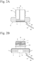
- the pouring spout 10, as illustrated in Fig. 2 and Fig. 3 comprises the tubular pouring part 11 and the attached part 15.
- the tubular pouring part 11 forms a cylinder.
- the attached part 15 is an area attached to the refill container 1 serving as a container provided with this pouring spout 10, and is provided on the one end A side in the extending direction L of the tubular pouring part 11.
- the tubular pouring part 11 is an area used when the contents of the refill container 1 provided with the pouring spout 10 are poured from the refill container 1.
- the tubular pouring part 11 has a hollow interior, and both ends in the extending direction L of the tubular pouring part 11 are open in a circular shape. That is, the channel 10b is formed in the interior of the tubular pouring part 11.
- the tubular pouring part 11 is configured to allow the inner side and the outer side of the refill container 1 to communicate.
- an interior of the guide 50 is hollow.
- a weight of the spout main body 10A of the pouring spout 10 can be reduced.
- an amount of resin required for molding the spout main body 10A of the pouring spout 10 can be made less than an amount for a mode in which a hollow interior is not provided.
- providing the guide 50 with a hollow interior is not required, and a configuration in which the interior of the guide 50 is filled with resin is also possible.
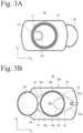
- the attached part 15, as illustrated in Fig 3B has a so-called boat shape.
- a boat shape refers to a shape in which side surface parts 16 of the attached part 15 on both sides in a horizontal direction (direction denoted by reference sign Y in Fig. 3 ) protrude toward the outer sides, and have acute angles that come to a point on both sides in a vertical direction (direction denoted by reference sign X in Fig. 3 ). Heights of the side surface parts 16 are uniformly formed.
- the closing member 20 that closes the channel 10b of the pouring spout 10 is configured so that the closing member 20 is removed by an external force applied from the other end B side opposite to the one end A side in the extending direction L of the tubular pouring part 11 from the inner circumferential surface of the tubular pouring part 11.
- a diameter of the closing member 20 is formed to the same size as or slightly smaller than an inner diameter of the channel 10b of the pouring spout 10.
- the channel 10b of the pouring spout 10 of the present embodiment has a circular cross-sectional shape, and thus the closing member 20 fitted into the channel 10b also has a circular outer shape.
- the outer shape of the closing member 20 is formed into a shape corresponding to the cross-sectional shape of the channel 10b of the pouring spout 10.
- the outer shape of the closing member 20 is formed into an elliptical shape corresponding to the cross-sectional shape of the channel 10b of the pouring spout 10.
- the closing member 20 With the outer shape of the closing member 20 formed into a shape corresponding to the cross-sectional shape of the channel 10b of the pouring spout 10, the closing member 20 closes the channel 10b without forming a gap between the closing member 20 and the inner circumferential surface of the channel 10b of the pouring spout 10 when the closing member 20 is fit onto the inner side of the channel 10b of the pouring spout 10.
- the lower surface of the closing member 20 is a surface facing the interior of the container (refill container 1) to which the pouring spout 10 is attached in a mode in which the closing member 20 is fitted into the channel 10b of the pouring spout 10.
- the coupling member 21 couples the closing member 20 and the spout main body 10A in such a manner that a force is applied in a direction in which the closing member 20 is separated from the channel 10b of the pouring spout 10.
- Both ends of the coupling member 21 couple the spout main body 10A and the closing member 20 as described above, and thus the closing member 20 is fitted onto the inner side of the channel 10b without the coupling member 21 getting pinched between the closing member 20 and the channel 10b. Further, when the closing member 20 is removed from the inner side of the channel 10b, the closing member 20 is maintained in a state of connection to the pouring spout 10 without being separated from the spout main body 10A.
- the coupling member 21 couples the closing member 20 and the spout main body 10A in such a manner that a force is applied in a direction in which the closing member 20 is separated from the channel 10b of the pouring spout 10, and thus the closing member 20 removed from the channel 10b is kept from blocking the channel 10b once again. As a result, it is possible to smoothly transfer contents from the refill container 1 into the packaging container 30.
- the pouring spout 10 described above is molded from a resin such as polyethylene, polypropylene, polyester, ethylene-vinyl copolymer, and polyvinyl chloride.
- a resin such as polyethylene, polypropylene, polyester, ethylene-vinyl copolymer, and polyvinyl chloride.
- the material is not limited as long as the pouring spout 10 is moldable, and examples of applicable raw materials of the resin include petroleum-derived materials, plant-derived materials, copolymers thereof, and blend resins thereof.
- the pouring spout 10 can be manufactured by various manufacturing methods. However, when manufacturing efficiency, manufacturing cost, and quality are considered, the spout main body 10A, the closing member 20, and the coupling member 21 are preferably integrally molded by injection-molding a resin.
- the manufacturing method for injection-molding a resin allows the spout main body 10A, the closing member 20, and the coupling member 21 to be integrally molded using the same material, making it possible to increase the manufacturing efficiency and keep the manufacturing cost to a low level. Further, once a die is manufactured, products having the identical quality can be repeatedly manufactured.
- the packaging container 30 is a container used after being refilled with contents stored in the refill container 1.
- the packaging container 30 is made of a resin or the like, for example.
- Fig. 4 shows an example of the packaging container 30.
- the packaging container 30 illustrated in Fig. 4 is configured by a container main body 31 provided with a handle 32, and the pouring unit 40 for pouring the contents stored in the container main body 31. This packaging container 30 is used by removing from the packaging container 30 the contents moved from the refill container 1 in an amount required when necessary.
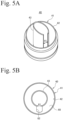
- Fig. 6 The procedure for refilling the packaging container 30 with the contents stored in the refill container 1, and the action of the pouring unit 40 and the pouring spout 10 of the present embodiment will now be described with reference to Fig. 6 .
- the refill container 1 and the container main body 31 of the packaging container 30 are not illustrated in Fig. 6 .
- the pouring spout 10 is attached to the refill container 1, which is a refill container, illustrated in Fig. 1
- the pouring unit 40 is provided to the packaging container 30 illustrated in Fig. 4 .
- the cap 19 is removed from the pouring spout 10, the refill container 1 is turned upside down, and the pouring spout 10 is positioned on a lower side of the refill container 1.
- the channel 10b of the pouring spout 10 is closed by the closing member 20, and thus the contents stored in the refill container 1 never spill out.
- the cap 49 is removed in advance from the main body part 41.
- the pouring spout 10 is matched with the position of the pouring unit 40 of the packaging container 30 from which the cap 19 is removed, and the nozzle 43 of the pouring unit 40 is inserted into the channel 10b of the pouring spout 10.
- the guide 50 formed in the channel 10b of the tubular pouring part 11 is fitted into the first slit 61 formed in the nozzle 43.
- the packaging container 30 is pressed downward.
- the tubular pouring part 11 constituting the pouring spout 10 of the refill container 1 moves from the tip end side to the base side of the nozzle 43 while guided in the extending direction of the nozzle 43.
- the closing member 20 is removed from the channel 10b constituting the inner side of the tubular pouring part 11. That is, the closing member 20 is removed by an external force applied from the other end B side (tip end side of the cylindrical pouring part) opposite to the one end A side (end part side provided with the attached part 15) in the extending direction L of the tubular pouring part from the inner circumferential surface of the tubular pouring part 11.
- the closing member 20, in a mode of removal from the inner circumferential surface, is fitted horizontally onto an inner circumferential surface of the tubular pouring part 11 on the one end A side thereof.
- the closing member 20 is configured as a separate body from the spout main body 10A, and is fitted into the channel 10b constituting the tubular pouring part 11, simply closing the channel 10b, and thus is smoothly removed from the channel 10b without causing the closing member 20 itself to be damage by the nozzle 43. As a result, simply the contents are moved into the packaging container 30 without producing broken pieces.
- the guide 50 formed in the tubular pouring part 11 is fitted into the first slit formed in the nozzle 43, and thus the pouring spout 10 of the refill container 1 is prevented from separating from the main body part 41 of the pouring unit 40 of the packaging container 30.
- the second slit 62 functions as an air vent hole and thus, while the packaging container 30 is refilled with contents from the refill container 1, contents stored in the refill container 1 is smoothly transferred into the packaging container.
- the nozzle 43 is inserted into the interior of the tubular pouring part 11 and, when the closing member 20 is removed from the spout main body 10A, a tip end part 11a of the tubular pouring part 11 comes into contact with an outer circumferential surface of the nozzle. That is, in a mode in which the nozzle 43 is inserted into the tubular pouring part 11, the tip end of the tubular pouring part 11 is formed to a size resulting in contact with the outer circumferential surface of a base portion of the nozzle 43.
- the contents poured from the refill container 1 (standing pouch) are moved to the packaging container 30 through the nozzle 43 without leaking to the outer side of the nozzle 43.
Landscapes
- Engineering & Computer Science (AREA)
- Mechanical Engineering (AREA)
- Closures For Containers (AREA)
- Bag Frames (AREA)
- Cartons (AREA)
Claims (3)
- Structure de couplage entre un bec verseur d'un contenant de recharge et une unité de versement d'un contenant de conditionnement comprenant une unité de versement (40) et un bec verseur (10) configurés pour être couplés ensemble, l'unité de versement (40) comprenant une buse (43) pour verser le contenu à partir d'un contenant de conditionnement (30), et une surface de paroi périphérique (42) entourant une périphérie extérieure de la buse (43), la buse (43) et la surface de paroi périphérique (42) étant reliées au niveau d'une base de la buse (43), et le bec verseur (10) étant utilisé pour un contenant de recharge (1) stockant un contenu pour remplir le contenant de conditionnement (30), et comprenant un corps principal de bec (10A) incluant une partie de versement tubulaire (11) avec un canal (10b) pour permettre le passage du contenu formé sur un côté intérieur, et une partie fixée (15) pouvant être fixée au contenant de recharge (1) sur un premier côté d'extrémité dans une direction d'extension de la partie de versement tubulaire (11), dans laquelle :l'unité de versement (40) comprend une première fente (61) formée par une partie manquante d'une paroi périphérique constituant la buse (43) dans une direction circonférentielle de celle-ci, dans une direction d'extension de la buse (43) ;la partie de versement tubulaire (11) comprend un guide (50) qui fait saillie à partir d'une paroi interne du canal (10b) vers un centre, s'étend dans une direction correspondant à la direction d'extension de la partie de versement tubulaire (11), est ajustée sur un côté intérieur de la première fente (61) de la buse (43), et guide la partie de versement tubulaire (11) dans la direction d'extension de la buse (43) ;le bec verseur (10) comprend en outre un élément de fermeture (20) pour fermer le canal (10b) sur le premier côté d'extrémité, configuré sous la forme d'un corps séparé du corps principal de bec (10A), et pour s'adapter sur une surface circonférentielle intérieure de la partie de versement tubulaire (11) sur le premier côté d'extrémité de celle-ci de telle sorte que l'élément de fermeture (20) est retiré par l'intermédiaire d'une force externe appliquée à partir de l'autre côté d'extrémité opposé au premier côté d'extrémité dans la direction d'extension de la partie de versement tubulaire (11) à partir de la surface circonférentielle intérieure de la partie de versement tubulaire (11), dans laquelle lorsque l'unité de versement et le bec verseur sont couplés ensemble, l'élément de fermeture est configuré pour être retiré de la surface circonférentielle intérieure de la partie de versement tubulaire ;caractérisée en ce que :l'élément de fermeture (20) est relié par l'intermédiaire d'un élément de couplage (21) au corps principal de bec (10A) ;l'élément de couplage (21) est constitué d'une résine et présente une forme de cordon ou de bande, dans lequel une première extrémité de l'élément de couplage (21) dans la direction longitudinale est reliée à une surface d'extrémité inférieure de la partie fixée (15) du corps principal de bec (10A) au niveau d'une position légèrement décalée vers le côté extérieur dans une direction radiale à partir d'une partie périphérique du canal (10b) ;l'autre extrémité de l'élément de couplage (21) dans la direction longitudinale est reliée à une surface inférieure (20b) de l'élément de fermeture (20), qui est une surface de l'élément de fermeture (20) qui est configurée pour faire face à l'intérieur du contenant de recharge (1) auquel le bec verseur (10) est fixé dans un mode dans lequel l'élément de fermeture (20) est ajusté dans le canal (10b) du bec verseur (10) ;dans laquelle l'élément de couplage (21) relie l'élément de fermeture (20) et la partie fixée (15) du corps principal de bec (10A) de telle sorte qu'une force soit appliquée dans une direction dans laquelle l'élément de fermeture (20) est séparé du canal (10b) du bec verseur (10) ;l'unité de versement (40) comprend une seconde fente (62) s'étendant à partir de la buse (43) vers un côté extérieur dans la direction radiale à la base de la buse (43) ; etla seconde fente (62) fonctionne comme un trou d'aération pour l'unité de versement (40) et le bec verseur (10) qui sont couplés.
- Structure de couplage entre une unité de versement (40) et un bec verseur (10) selon la revendication 1, dans laquelle une extrémité de pointe (11a) de la partie de versement tubulaire (11) est formée à une taille résultant en un contact avec la surface circonférentielle extérieure d'une partie de base de la buse (43) dans un mode dans lequel la buse (43) est insérée dans la partie de versement tubulaire (11).
- Structure de couplage entre une unité de versement (40) et un bec verseur (10) selon la revendication 1, dans laquelle le guide (50) s'étend à partir d'une position d'une extrémité de pointe (11a) de la partie de versement tubulaire (11) vers un côté arrière, dans une direction correspondant à la direction d'extension de la partie de versement tubulaire (11).
Applications Claiming Priority (2)
| Application Number | Priority Date | Filing Date | Title |
|---|---|---|---|
| JP2016238188A JP6236139B1 (ja) | 2016-12-08 | 2016-12-08 | 詰め替え容器の注出用スパウト及び包装容器の注出ユニットとの連結構造 |
| PCT/JP2017/043945 WO2018105687A1 (fr) | 2016-12-08 | 2017-12-07 | Structure de liaison entre bec verseur de récipient de recharge et unité de versage de récipient d'emballage |
Publications (3)
| Publication Number | Publication Date |
|---|---|
| EP3543165A1 EP3543165A1 (fr) | 2019-09-25 |
| EP3543165A4 EP3543165A4 (fr) | 2019-12-11 |
| EP3543165B1 true EP3543165B1 (fr) | 2025-07-09 |
Family
ID=60417464
Family Applications (1)
| Application Number | Title | Priority Date | Filing Date |
|---|---|---|---|
| EP17877876.7A Active EP3543165B1 (fr) | 2016-12-08 | 2017-12-07 | Structure de liaison entre bec verseur de récipient de recharge et unité de versage de récipient d'emballage |
Country Status (8)
| Country | Link |
|---|---|
| US (1) | US11155390B2 (fr) |
| EP (1) | EP3543165B1 (fr) |
| JP (1) | JP6236139B1 (fr) |
| KR (1) | KR102492789B1 (fr) |
| CN (1) | CN110035957B (fr) |
| MY (1) | MY194565A (fr) |
| PH (1) | PH12019501259A1 (fr) |
| WO (1) | WO2018105687A1 (fr) |
Families Citing this family (9)
| Publication number | Priority date | Publication date | Assignee | Title |
|---|---|---|---|---|
| JP6960731B2 (ja) * | 2016-12-08 | 2021-11-05 | 藤森工業株式会社 | 容器の注出用スパウト |
| JP7245010B2 (ja) * | 2018-08-06 | 2023-03-23 | 藤森工業株式会社 | 注出スパウト |
| JP7193305B2 (ja) * | 2018-10-30 | 2022-12-20 | 藤森工業株式会社 | 注出スパウト |
| JP7174593B2 (ja) * | 2018-10-30 | 2022-11-17 | 藤森工業株式会社 | 注出スパウト及び詰め替え容器から包装容器への内容物補充方法 |
| JP7264658B2 (ja) * | 2019-02-05 | 2023-04-25 | 藤森工業株式会社 | 注出用スパウト、閉鎖部材付き注出用スパウト |
| JP7297484B2 (ja) * | 2019-03-22 | 2023-06-26 | 藤森工業株式会社 | 注出用スパウト、閉鎖部材付き注出用スパウト |
| CN111846592B (zh) * | 2020-08-13 | 2025-05-06 | 广州曼盛包装有限公司 | 一种连接嘴和补充液包装袋 |
| USD957188S1 (en) * | 2020-12-04 | 2022-07-12 | Automatic Bar Controls, Inc. | Inlet suction strainer |
| FR3150508B1 (fr) * | 2023-06-27 | 2025-06-13 | Soc Lorraine De Capsules Metalliques Manufacture De Bouchage | Système de bouchage pour poche souple destiné à rester totalement attaché à la poche souple. |
Family Cites Families (34)
| Publication number | Priority date | Publication date | Assignee | Title |
|---|---|---|---|---|
| US2601039A (en) * | 1949-12-01 | 1952-06-17 | Livingstone Jay Gould | Pouring spout |
| US2851196A (en) * | 1954-01-11 | 1958-09-09 | Jay G Livingstone | Adapter |
| US3006514A (en) * | 1958-03-12 | 1961-10-31 | Pressure Dispensers Inc | Dispensing valve |
| US3098586A (en) * | 1961-02-14 | 1963-07-23 | Wasserberg Charles | Liquid pouring device and insert member for a bottle |
| NO120506L (fr) * | 1966-07-11 | |||
| US3386626A (en) * | 1967-02-09 | 1968-06-04 | Kearney Patrick | Non-refillable bottle and pourer |
| US3506167A (en) * | 1968-04-01 | 1970-04-14 | Clair S Orr | Venting device for water bottles |
| US4241855A (en) * | 1979-04-16 | 1980-12-30 | Kikkoman Foods, Inc. | Flow controlling pouring spout |
| US4267941A (en) * | 1979-12-26 | 1981-05-19 | Illinois Tool Works Inc. | Breather cap |
| DE3625327C1 (de) * | 1986-07-26 | 1988-02-18 | Heidenhain Gmbh Dr Johannes | Lichtelektrische Positionsmesseinrichtung |
| US5377882A (en) * | 1990-09-04 | 1995-01-03 | Pham; Ninh G. | Container and closure |
| US5232110A (en) * | 1991-12-04 | 1993-08-03 | Purnell Peter F | Container closure |
| JPH10119974A (ja) * | 1996-10-17 | 1998-05-12 | Sawa:Kk | 液体用容器の注口補助具 |
| NL1011960C2 (nl) * | 1999-05-04 | 2000-11-07 | Itsac Nv | Houder, in het bijzonder een flexibele houder, met een afsluitbare opening en werkwijze voor het vullen van een dergelijke houder. |
| JP4628779B2 (ja) * | 2004-08-26 | 2011-02-09 | 藤森工業株式会社 | 詰め替え容器用スパウトおよび詰め替え容器 |
| JP5345279B2 (ja) * | 2006-07-13 | 2013-11-20 | アサヒビール株式会社 | バッグインボックス用注出口シール構造およびこれを備えるバッグインボックス |
| CN101570256B (zh) * | 2008-04-17 | 2013-01-23 | 杨泰和 | 封盖具掀开预力的套置压开型储存装置 |
| JP5312851B2 (ja) * | 2008-06-12 | 2013-10-09 | ライオン株式会社 | 液体注出容器 |
| JP4490493B2 (ja) * | 2008-07-11 | 2010-06-23 | 株式会社悠心 | 逆止機能ノズルを備えるフレキシブル包装袋 |
| US8474665B2 (en) * | 2008-07-24 | 2013-07-02 | Sports Pouch Beverage Co., Inc. | Re-sealable spigot for a collapsible beverage container |
| JP5365361B2 (ja) * | 2009-03-26 | 2013-12-11 | 凸版印刷株式会社 | 詰替え容器用口栓 |
| JP5207312B2 (ja) | 2009-04-30 | 2013-06-12 | 株式会社吉野工業所 | 詰め替え容器 |
| JP5321896B2 (ja) * | 2009-05-29 | 2013-10-23 | 株式会社吉野工業所 | 詰め替え容器 |
| JP5683235B2 (ja) * | 2009-12-04 | 2015-03-11 | 花王株式会社 | 注出容器 |
| CN103282287B (zh) * | 2010-12-27 | 2015-06-03 | 花王株式会社 | 包装体、换装方法以及包装体套件 |
| JP5945097B2 (ja) * | 2011-01-31 | 2016-07-05 | 株式会社吉野工業所 | 詰め替え容器 |
| JP5551646B2 (ja) * | 2011-03-31 | 2014-07-16 | 株式会社吉野工業所 | 詰め替え容器 |
| JP5790114B2 (ja) * | 2011-04-19 | 2015-10-07 | 凸版印刷株式会社 | 繰り返し使用容器 |
| JP5953041B2 (ja) * | 2011-12-28 | 2016-07-13 | 花王株式会社 | 詰替え容器用栓部材 |
| WO2013099978A1 (fr) * | 2011-12-28 | 2013-07-04 | 花王株式会社 | Élément de bouchon pour récipient de recharge |
| JP5955585B2 (ja) * | 2012-02-28 | 2016-07-20 | 花王株式会社 | 注出キャップ |
| JP2013203464A (ja) | 2012-03-29 | 2013-10-07 | Toppan Printing Co Ltd | 詰め替え容器 |
| CN202784179U (zh) * | 2012-09-28 | 2013-03-13 | 徐洁 | 纯净水桶盖 |
| JP6183847B2 (ja) * | 2012-11-30 | 2017-08-23 | 花王株式会社 | 詰替え容器用栓体 |
-
2016
- 2016-12-08 JP JP2016238188A patent/JP6236139B1/ja active Active
-
2017
- 2017-12-07 CN CN201780074890.2A patent/CN110035957B/zh active Active
- 2017-12-07 US US16/467,287 patent/US11155390B2/en active Active
- 2017-12-07 KR KR1020197016143A patent/KR102492789B1/ko active Active
- 2017-12-07 EP EP17877876.7A patent/EP3543165B1/fr active Active
- 2017-12-07 MY MYPI2019003185A patent/MY194565A/en unknown
- 2017-12-07 WO PCT/JP2017/043945 patent/WO2018105687A1/fr not_active Ceased
-
2019
- 2019-06-06 PH PH12019501259A patent/PH12019501259A1/en unknown
Also Published As
| Publication number | Publication date |
|---|---|
| JP2018095259A (ja) | 2018-06-21 |
| PH12019501259A1 (en) | 2019-11-04 |
| EP3543165A4 (fr) | 2019-12-11 |
| US11155390B2 (en) | 2021-10-26 |
| CN110035957A (zh) | 2019-07-19 |
| CN110035957B (zh) | 2022-05-06 |
| MY194565A (en) | 2022-12-02 |
| US20200062464A1 (en) | 2020-02-27 |
| KR102492789B1 (ko) | 2023-01-27 |
| WO2018105687A1 (fr) | 2018-06-14 |
| EP3543165A1 (fr) | 2019-09-25 |
| KR20190093573A (ko) | 2019-08-09 |
| JP6236139B1 (ja) | 2017-11-22 |
Similar Documents
| Publication | Publication Date | Title |
|---|---|---|
| EP3543165B1 (fr) | Structure de liaison entre bec verseur de récipient de recharge et unité de versage de récipient d'emballage | |
| KR100572686B1 (ko) | 깔때기 형태로 연장되어 있는 유출로가 구비된 밀폐요소와필름백 | |
| US11203468B2 (en) | Pouring spout of container | |
| US9523596B2 (en) | Auto-refill single dose dispenser | |
| JP6243354B2 (ja) | リフィル容器用注出構造 | |
| EP3543162B1 (fr) | Bec verseur pour un récipient de remplissage | |
| JP2018062351A (ja) | 詰め替え容器用スパウト及びスパウト付き詰め替え容器 | |
| TWI625282B (zh) | Refilling container plug member, refilling method, and refilling container | |
| JP5756357B2 (ja) | 詰替え用軟包装容器 | |
| JP5365283B2 (ja) | 詰替え容器 | |
| JP6083855B2 (ja) | 詰替え容器用栓体 | |
| JP5121144B2 (ja) | パウチ用口栓、口栓付きパウチ、および包装体 | |
| EP3875390B1 (fr) | Bec verseur | |
| JP7703389B2 (ja) | ヒンジキャップ | |
| JP5953041B2 (ja) | 詰替え容器用栓部材 | |
| JP6018751B2 (ja) | 詰替え容器用栓部材 | |
| JP4605568B2 (ja) | バッグインボックス用充填口 | |
| JP2011031947A (ja) | ブロー成形容器 | |
| JP2024104695A (ja) | 詰替え容器用栓体及びこれを具備する詰替え容器 | |
| JP2015024864A (ja) | 詰替え用軟包装容器 | |
| JP2023049855A (ja) | 注出具 | |
| JP2006306472A (ja) | 合成樹脂製薄肉容器 |
Legal Events
| Date | Code | Title | Description |
|---|---|---|---|
| STAA | Information on the status of an ep patent application or granted ep patent |
Free format text: STATUS: THE INTERNATIONAL PUBLICATION HAS BEEN MADE |
|
| PUAI | Public reference made under article 153(3) epc to a published international application that has entered the european phase |
Free format text: ORIGINAL CODE: 0009012 |
|
| STAA | Information on the status of an ep patent application or granted ep patent |
Free format text: STATUS: REQUEST FOR EXAMINATION WAS MADE |
|
| 17P | Request for examination filed |
Effective date: 20190618 |
|
| AK | Designated contracting states |
Kind code of ref document: A1 Designated state(s): AL AT BE BG CH CY CZ DE DK EE ES FI FR GB GR HR HU IE IS IT LI LT LU LV MC MK MT NL NO PL PT RO RS SE SI SK SM TR |
|
| AX | Request for extension of the european patent |
Extension state: BA ME |
|
| A4 | Supplementary search report drawn up and despatched |
Effective date: 20191113 |
|
| RIC1 | Information provided on ipc code assigned before grant |
Ipc: B65D 47/06 20060101AFI20191107BHEP Ipc: B65D 75/58 20060101ALI20191107BHEP |
|
| DAV | Request for validation of the european patent (deleted) | ||
| DAX | Request for extension of the european patent (deleted) | ||
| STAA | Information on the status of an ep patent application or granted ep patent |
Free format text: STATUS: EXAMINATION IS IN PROGRESS |
|
| 17Q | First examination report despatched |
Effective date: 20200901 |
|
| RAP3 | Party data changed (applicant data changed or rights of an application transferred) |
Owner name: ZACROS CORPORATION |
|
| GRAP | Despatch of communication of intention to grant a patent |
Free format text: ORIGINAL CODE: EPIDOSNIGR1 |
|
| STAA | Information on the status of an ep patent application or granted ep patent |
Free format text: STATUS: GRANT OF PATENT IS INTENDED |
|
| INTG | Intention to grant announced |
Effective date: 20250324 |
|
| GRAS | Grant fee paid |
Free format text: ORIGINAL CODE: EPIDOSNIGR3 |
|
| GRAA | (expected) grant |
Free format text: ORIGINAL CODE: 0009210 |
|
| STAA | Information on the status of an ep patent application or granted ep patent |
Free format text: STATUS: THE PATENT HAS BEEN GRANTED |
|
| AK | Designated contracting states |
Kind code of ref document: B1 Designated state(s): AL AT BE BG CH CY CZ DE DK EE ES FI FR GB GR HR HU IE IS IT LI LT LU LV MC MK MT NL NO PL PT RO RS SE SI SK SM TR |
|
| REG | Reference to a national code |
Ref country code: GB Ref legal event code: FG4D |
|
| REG | Reference to a national code |
Ref country code: CH Ref legal event code: EP |
|
| REG | Reference to a national code |
Ref country code: IE Ref legal event code: FG4D |
|
| REG | Reference to a national code |
Ref country code: DE Ref legal event code: R096 Ref document number: 602017090512 Country of ref document: DE |
|
| REG | Reference to a national code |
Ref country code: NL Ref legal event code: MP Effective date: 20250709 |
|
| PG25 | Lapsed in a contracting state [announced via postgrant information from national office to epo] |
Ref country code: PT Free format text: LAPSE BECAUSE OF FAILURE TO SUBMIT A TRANSLATION OF THE DESCRIPTION OR TO PAY THE FEE WITHIN THE PRESCRIBED TIME-LIMIT Effective date: 20251110 |
|
| PG25 | Lapsed in a contracting state [announced via postgrant information from national office to epo] |
Ref country code: NL Free format text: LAPSE BECAUSE OF FAILURE TO SUBMIT A TRANSLATION OF THE DESCRIPTION OR TO PAY THE FEE WITHIN THE PRESCRIBED TIME-LIMIT Effective date: 20250709 |
|
| REG | Reference to a national code |
Ref country code: AT Ref legal event code: MK05 Ref document number: 1811684 Country of ref document: AT Kind code of ref document: T Effective date: 20250709 |
|
| PG25 | Lapsed in a contracting state [announced via postgrant information from national office to epo] |
Ref country code: IS Free format text: LAPSE BECAUSE OF FAILURE TO SUBMIT A TRANSLATION OF THE DESCRIPTION OR TO PAY THE FEE WITHIN THE PRESCRIBED TIME-LIMIT Effective date: 20251109 |
|
| PGFP | Annual fee paid to national office [announced via postgrant information from national office to epo] |
Ref country code: DE Payment date: 20251211 Year of fee payment: 9 |
|
| PGFP | Annual fee paid to national office [announced via postgrant information from national office to epo] |
Ref country code: GB Payment date: 20251219 Year of fee payment: 9 |
|
| PG25 | Lapsed in a contracting state [announced via postgrant information from national office to epo] |
Ref country code: NO Free format text: LAPSE BECAUSE OF FAILURE TO SUBMIT A TRANSLATION OF THE DESCRIPTION OR TO PAY THE FEE WITHIN THE PRESCRIBED TIME-LIMIT Effective date: 20251009 |
|
| REG | Reference to a national code |
Ref country code: LT Ref legal event code: MG9D |
|
| PG25 | Lapsed in a contracting state [announced via postgrant information from national office to epo] |
Ref country code: AT Free format text: LAPSE BECAUSE OF FAILURE TO SUBMIT A TRANSLATION OF THE DESCRIPTION OR TO PAY THE FEE WITHIN THE PRESCRIBED TIME-LIMIT Effective date: 20250709 |
|
| PG25 | Lapsed in a contracting state [announced via postgrant information from national office to epo] |
Ref country code: FI Free format text: LAPSE BECAUSE OF FAILURE TO SUBMIT A TRANSLATION OF THE DESCRIPTION OR TO PAY THE FEE WITHIN THE PRESCRIBED TIME-LIMIT Effective date: 20250709 |
|
| PGFP | Annual fee paid to national office [announced via postgrant information from national office to epo] |
Ref country code: IT Payment date: 20251223 Year of fee payment: 9 |
|
| PG25 | Lapsed in a contracting state [announced via postgrant information from national office to epo] |
Ref country code: HR Free format text: LAPSE BECAUSE OF FAILURE TO SUBMIT A TRANSLATION OF THE DESCRIPTION OR TO PAY THE FEE WITHIN THE PRESCRIBED TIME-LIMIT Effective date: 20250709 |
|
| PGFP | Annual fee paid to national office [announced via postgrant information from national office to epo] |
Ref country code: FR Payment date: 20251229 Year of fee payment: 9 |
|
| PG25 | Lapsed in a contracting state [announced via postgrant information from national office to epo] |
Ref country code: GR Free format text: LAPSE BECAUSE OF FAILURE TO SUBMIT A TRANSLATION OF THE DESCRIPTION OR TO PAY THE FEE WITHIN THE PRESCRIBED TIME-LIMIT Effective date: 20251010 |
|
| PG25 | Lapsed in a contracting state [announced via postgrant information from national office to epo] |
Ref country code: SE Free format text: LAPSE BECAUSE OF FAILURE TO SUBMIT A TRANSLATION OF THE DESCRIPTION OR TO PAY THE FEE WITHIN THE PRESCRIBED TIME-LIMIT Effective date: 20250709 |
|
| PG25 | Lapsed in a contracting state [announced via postgrant information from national office to epo] |
Ref country code: LV Free format text: LAPSE BECAUSE OF FAILURE TO SUBMIT A TRANSLATION OF THE DESCRIPTION OR TO PAY THE FEE WITHIN THE PRESCRIBED TIME-LIMIT Effective date: 20250709 |
|
| PG25 | Lapsed in a contracting state [announced via postgrant information from national office to epo] |
Ref country code: PL Free format text: LAPSE BECAUSE OF FAILURE TO SUBMIT A TRANSLATION OF THE DESCRIPTION OR TO PAY THE FEE WITHIN THE PRESCRIBED TIME-LIMIT Effective date: 20250709 Ref country code: BG Free format text: LAPSE BECAUSE OF FAILURE TO SUBMIT A TRANSLATION OF THE DESCRIPTION OR TO PAY THE FEE WITHIN THE PRESCRIBED TIME-LIMIT Effective date: 20250709 |
|
| PG25 | Lapsed in a contracting state [announced via postgrant information from national office to epo] |
Ref country code: RS Free format text: LAPSE BECAUSE OF FAILURE TO SUBMIT A TRANSLATION OF THE DESCRIPTION OR TO PAY THE FEE WITHIN THE PRESCRIBED TIME-LIMIT Effective date: 20251009 |
|
| PG25 | Lapsed in a contracting state [announced via postgrant information from national office to epo] |
Ref country code: ES Free format text: LAPSE BECAUSE OF FAILURE TO SUBMIT A TRANSLATION OF THE DESCRIPTION OR TO PAY THE FEE WITHIN THE PRESCRIBED TIME-LIMIT Effective date: 20250709 |
|
| PG25 | Lapsed in a contracting state [announced via postgrant information from national office to epo] |
Ref country code: RO Free format text: LAPSE BECAUSE OF FAILURE TO SUBMIT A TRANSLATION OF THE DESCRIPTION OR TO PAY THE FEE WITHIN THE PRESCRIBED TIME-LIMIT Effective date: 20250709 |
|
| PG25 | Lapsed in a contracting state [announced via postgrant information from national office to epo] |
Ref country code: SM Free format text: LAPSE BECAUSE OF FAILURE TO SUBMIT A TRANSLATION OF THE DESCRIPTION OR TO PAY THE FEE WITHIN THE PRESCRIBED TIME-LIMIT Effective date: 20250709 |
|
| PG25 | Lapsed in a contracting state [announced via postgrant information from national office to epo] |
Ref country code: DK Free format text: LAPSE BECAUSE OF FAILURE TO SUBMIT A TRANSLATION OF THE DESCRIPTION OR TO PAY THE FEE WITHIN THE PRESCRIBED TIME-LIMIT Effective date: 20250709 |