EP3543505B1 - Air de refroidissement à refroidissement intermédiaire avec des caractéristiques combinées - Google Patents
Air de refroidissement à refroidissement intermédiaire avec des caractéristiques combinées Download PDFInfo
- Publication number
- EP3543505B1 EP3543505B1 EP19164741.1A EP19164741A EP3543505B1 EP 3543505 B1 EP3543505 B1 EP 3543505B1 EP 19164741 A EP19164741 A EP 19164741A EP 3543505 B1 EP3543505 B1 EP 3543505B1
- Authority
- EP
- European Patent Office
- Prior art keywords
- gas turbine
- cooling
- compressor
- turbine engine
- air
- Prior art date
- Legal status (The legal status is an assumption and is not a legal conclusion. Google has not performed a legal analysis and makes no representation as to the accuracy of the status listed.)
- Active
Links
Images


Classifications
-
- F—MECHANICAL ENGINEERING; LIGHTING; HEATING; WEAPONS; BLASTING
- F02—COMBUSTION ENGINES; HOT-GAS OR COMBUSTION-PRODUCT ENGINE PLANTS
- F02C—GAS-TURBINE PLANTS; AIR INTAKES FOR JET-PROPULSION PLANTS; CONTROLLING FUEL SUPPLY IN AIR-BREATHING JET-PROPULSION PLANTS
- F02C7/00—Features, components parts, details or accessories, not provided for in, or of interest apart form groups F02C1/00 - F02C6/00; Air intakes for jet-propulsion plants
- F02C7/12—Cooling of plants
- F02C7/16—Cooling of plants characterised by cooling medium
- F02C7/18—Cooling of plants characterised by cooling medium the medium being gaseous, e.g. air
- F02C7/185—Cooling means for reducing the temperature of the cooling air or gas
-
- F—MECHANICAL ENGINEERING; LIGHTING; HEATING; WEAPONS; BLASTING
- F02—COMBUSTION ENGINES; HOT-GAS OR COMBUSTION-PRODUCT ENGINE PLANTS
- F02C—GAS-TURBINE PLANTS; AIR INTAKES FOR JET-PROPULSION PLANTS; CONTROLLING FUEL SUPPLY IN AIR-BREATHING JET-PROPULSION PLANTS
- F02C6/00—Plural gas-turbine plants; Combinations of gas-turbine plants with other apparatus; Adaptations of gas-turbine plants for special use
- F02C6/04—Gas-turbine plants providing heated or pressurised working fluid for other apparatus, e.g. without mechanical power output
- F02C6/06—Gas-turbine plants providing heated or pressurised working fluid for other apparatus, e.g. without mechanical power output providing compressed gas
- F02C6/08—Gas-turbine plants providing heated or pressurised working fluid for other apparatus, e.g. without mechanical power output providing compressed gas the gas being bled from the gas-turbine compressor
-
- F—MECHANICAL ENGINEERING; LIGHTING; HEATING; WEAPONS; BLASTING
- F04—POSITIVE - DISPLACEMENT MACHINES FOR LIQUIDS; PUMPS FOR LIQUIDS OR ELASTIC FLUIDS
- F04D—NON-POSITIVE-DISPLACEMENT PUMPS
- F04D29/00—Details, component parts, or accessories
- F04D29/58—Cooling; Heating; Diminishing heat transfer
- F04D29/582—Cooling; Heating; Diminishing heat transfer specially adapted for elastic fluid pumps
- F04D29/5826—Cooling at least part of the working fluid in a heat exchanger
- F04D29/5833—Cooling at least part of the working fluid in a heat exchanger flow schemes and regulation thereto
-
- F—MECHANICAL ENGINEERING; LIGHTING; HEATING; WEAPONS; BLASTING
- F05—INDEXING SCHEMES RELATING TO ENGINES OR PUMPS IN VARIOUS SUBCLASSES OF CLASSES F01-F04
- F05D—INDEXING SCHEME FOR ASPECTS RELATING TO NON-POSITIVE-DISPLACEMENT MACHINES OR ENGINES, GAS-TURBINES OR JET-PROPULSION PLANTS
- F05D2220/00—Application
- F05D2220/30—Application in turbines
- F05D2220/32—Application in turbines in gas turbines
- F05D2220/323—Application in turbines in gas turbines for aircraft propulsion, e.g. jet engines
-
- F—MECHANICAL ENGINEERING; LIGHTING; HEATING; WEAPONS; BLASTING
- F05—INDEXING SCHEMES RELATING TO ENGINES OR PUMPS IN VARIOUS SUBCLASSES OF CLASSES F01-F04
- F05D—INDEXING SCHEME FOR ASPECTS RELATING TO NON-POSITIVE-DISPLACEMENT MACHINES OR ENGINES, GAS-TURBINES OR JET-PROPULSION PLANTS
- F05D2260/00—Function
- F05D2260/20—Heat transfer, e.g. cooling
- F05D2260/211—Heat transfer, e.g. cooling by intercooling, e.g. during a compression cycle
-
- F—MECHANICAL ENGINEERING; LIGHTING; HEATING; WEAPONS; BLASTING
- F05—INDEXING SCHEMES RELATING TO ENGINES OR PUMPS IN VARIOUS SUBCLASSES OF CLASSES F01-F04
- F05D—INDEXING SCHEME FOR ASPECTS RELATING TO NON-POSITIVE-DISPLACEMENT MACHINES OR ENGINES, GAS-TURBINES OR JET-PROPULSION PLANTS
- F05D2260/00—Function
- F05D2260/20—Heat transfer, e.g. cooling
- F05D2260/213—Heat transfer, e.g. cooling by the provision of a heat exchanger within the cooling circuit
-
- F—MECHANICAL ENGINEERING; LIGHTING; HEATING; WEAPONS; BLASTING
- F05—INDEXING SCHEMES RELATING TO ENGINES OR PUMPS IN VARIOUS SUBCLASSES OF CLASSES F01-F04
- F05D—INDEXING SCHEME FOR ASPECTS RELATING TO NON-POSITIVE-DISPLACEMENT MACHINES OR ENGINES, GAS-TURBINES OR JET-PROPULSION PLANTS
- F05D2260/00—Function
- F05D2260/20—Heat transfer, e.g. cooling
- F05D2260/231—Preventing heat transfer
-
- Y—GENERAL TAGGING OF NEW TECHNOLOGICAL DEVELOPMENTS; GENERAL TAGGING OF CROSS-SECTIONAL TECHNOLOGIES SPANNING OVER SEVERAL SECTIONS OF THE IPC; TECHNICAL SUBJECTS COVERED BY FORMER USPC CROSS-REFERENCE ART COLLECTIONS [XRACs] AND DIGESTS
- Y02—TECHNOLOGIES OR APPLICATIONS FOR MITIGATION OR ADAPTATION AGAINST CLIMATE CHANGE
- Y02T—CLIMATE CHANGE MITIGATION TECHNOLOGIES RELATED TO TRANSPORTATION
- Y02T50/00—Aeronautics or air transport
- Y02T50/60—Efficient propulsion technologies, e.g. for aircraft
Definitions
- This application relates to an intercooled cooling air supply system for cooling rotatable components in a gas turbine engine.
- Gas turbine engines typically include a fan delivering air into a bypass air as propulsion air.
- the fan also delivers air into a core engine where it enters a compressor section.
- the air is compressed and delivered into a combustion section where it is mixed with fuel and ignited. Products of this combustion pass downstream over turbine rotors causing them to rotate.
- Modern gas turbine engines are operating at higher and higher compressor pressures and, hence, temperatures. Further, the turbine sections are being exposed to higher temperature and pressures.
- EP3296543A1 discloses a prior art gas turbine engine according to the preamble of claim 1.
- US2016/312615A1 , US2017/306794A1 and EP3109436A1 disclose other prior art arrangements.
- a gas turbine engine is provided as set forth in claim 1.
- the air downstream of the cooling compressor passes through struts in a diffuser downstream of the main compressor section.
- the mixing chamber is radially inward of said struts.
- the mixing chamber is upstream of a turbine blade in said turbine section.
- the means for stopping flow between the cooling compressor and the plurality of rotating components includes a clutch.
- the means for stopping flow between the heat exchanger and the cooling compressor includes a shut off valve.
- a check valve is placed on the first tap between the main compressor section and the heat exchanger.
- the heat exchanger is received within a chamber defined between an outer core housing and an inner housing which is radially inward of a bypass duct.
- the cooling air valve is positioned at an upstream end of the chamber.
- the cooling air valve is positioned at a location downstream of the heat exchanger.
- a cooling compressor pressure ratio of the air downstream of the cooling compressor, and upstream of said mixing chamber, compared to a pressure of air downstream of the downstream most location is selected to be greater than or equal to 1.02.
- FIG. 1 schematically illustrates a gas turbine engine 20.
- the gas turbine engine 20 is disclosed herein as a two-spool turbofan that generally incorporates a fan section 22, a compressor section 24, a combustor section 26 and a turbine section 28.
- the fan section 22 drives air along a bypass flow path B in a bypass duct defined within a nacelle 15, and also drives air along a core flow path C for compression and communication into the combustor section 26 then expansion through the turbine section 28.
- FIG. 1 schematically illustrates a gas turbine engine 20.
- the gas turbine engine 20 is disclosed herein as a two-spool turbofan that generally incorporates a fan section 22, a compressor section 24, a combustor section 26 and a turbine section 28.
- the fan section 22 drives air along a bypass flow path B in a bypass duct defined within a nacelle 15, and also drives air along a core flow path C for compression and communication into the combustor section 26 then expansion through the turbine section 28.
- FIG. 1 schematic
- the exemplary engine 20 generally includes a low speed spool 30 and a high speed spool 32 mounted for rotation about an engine central longitudinal axis A relative to an engine static structure 36 via several bearing systems 38. It should be understood that various bearing systems 38 at various locations may alternatively or additionally be provided, and the location of bearing systems 38 may be varied as appropriate to the application.
- the low speed spool 30 generally includes an inner shaft 40 that interconnects a fan 42, a first (or low) pressure compressor 44 and a first (or low) pressure turbine 46.
- the inner shaft 40 is connected to the fan 42 through a speed change mechanism, which in exemplary gas turbine engine 20 is illustrated as a geared architecture 48 to drive the fan 42 at a lower speed than the low speed spool 30.
- the high speed spool 32 includes an outer shaft 50 that interconnects a second (or high) pressure compressor 52 and a second (or high) pressure turbine 54.
- a combustor 56 is arranged in exemplary gas turbine 20 between the high pressure compressor 52 and the high pressure turbine 54.
- a mid-turbine frame 57 of the engine static structure 36 is arranged generally between the high pressure turbine 54 and the low pressure turbine 46.
- the mid-turbine frame 57 further supports bearing systems 38 in the turbine section 28.
- the inner shaft 40 and the outer shaft 50 are concentric and rotate via bearing systems 38 about the engine central longitudinal axis A which is collinear with their longitudinal axes.
- the core airflow is compressed by the low pressure compressor 44 then the high pressure compressor 52, mixed and burned with fuel in the combustor 56, then expanded over the high pressure turbine 54 and low pressure turbine 46.
- the mid-turbine frame 57 includes airfoils 59 which are in the core airflow path C.
- the turbines 46, 54 rotationally drive the respective low speed spool 30 and high speed spool 32 in response to the expansion.
- gear system 48 may be located aft of combustor section 26 or even aft of turbine section 28, and fan section 22 may be positioned forward or aft of the location of gear system 48.
- the engine 20 in one example is a high-bypass geared aircraft engine.
- the engine 20 bypass ratio is greater than about six, with an example embodiment being greater than about ten
- the geared architecture 48 is an epicyclic gear train, such as a planetary gear system or other gear system, with a gear reduction ratio of greater than about 2.3 and the low pressure turbine 46 has a pressure ratio that is greater than about five.
- the engine 20 bypass ratio is greater than about ten
- the fan diameter is significantly larger than that of the low pressure compressor 44
- the low pressure turbine 46 has a pressure ratio that is greater than about five.
- Low pressure turbine 46 pressure ratio is pressure measured prior to inlet of low pressure turbine 46 as related to the pressure at the outlet of the low pressure turbine 46 prior to an exhaust nozzle.
- the geared architecture 48 may be an epicycle gear train, such as a planetary gear system or other gear system, with a gear reduction ratio of greater than about 2.3:1. It should be understood, however, that the above parameters are only exemplary of one embodiment of a geared architecture engine and that the present invention is applicable to other gas turbine engines including direct drive turbofans.
- the fan section 22 of the engine 20 is designed for a particular flight condition -- typically cruise at about 0.8 Mach and about 35,000 feet (10,668 meters).
- the flight condition of 0.8 Mach and 35,000 ft (10,668 meters), with the engine at its best fuel consumption - also known as "bucket cruise Thrust Specific Fuel Consumption ('TSFC')" - is the industry standard parameter of lbm of fuel being burned divided by lbf of thrust the engine produces at that minimum point.
- "Low fan pressure ratio” is the pressure ratio across the fan blade alone, without a Fan Exit Guide Vane (“FEGV”) system.
- the low fan pressure ratio as disclosed herein according to one non-limiting embodiment is less than about 1.45.
- the "Low corrected fan tip speed” as disclosed herein according to one non-limiting embodiment is less than about 1150 ft / second (350.5 meters/second).
- a commercial gas turbine engine as illustrated in Figure 1 , may benefit from the following features of this disclosure.
- the Figure 1 engines could be said to be designed to operate subsonically with an overall pressure ratio at the exit of the compressor divided by the inlet pressure at the entrance to the fan blade of greater than 40 at an 86 deg F (30°C) day at sea level take off operation.
- the intercooled cooling system as disclosed below may also provide benefits in other type gas turbine engines, such as direct drive engine where the fan is directly driven by a turbine and connecting shaft and engines utilized for military aircraft where the overall pressure ratio is above 40 during supersonic operation.
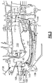
- FIG. 2A shows an intercooled cooling system 100.
- a core engine housing 102 is defined inwardly of the bypass duct receiving bypass air B and outwardly of the compressor section.
- An inner housing 104 is also outwardly of a low pressure compressor 106 and a high pressure compressor 108.
- An intermediate chamber 105 is defined between the housings 102 and 104.
- a downstream most point 109 in the high pressure compressor 108 defines a location where a pressure is at, or about, the highest pressure compressed air to be seen in the core of the engine. Further, air downstream of the point 109 is at about the highest temperature (known as T 3 ), and may also surround a combustor 110.
- a diffuser is downstream of the high pressure compressor 108.
- Cooling air from the intercooled cooling system 100 may cool a first turbine vane row 112 and a first turbine blade row 114 of a high pressure turbine. In addition, or alternatively, the air may also cool a downstream most disk and hub in the high pressure compressor 108.
- Air is tapped as shown at 118 from a location which is upstream of the downstream most location 109.
- the air 118 is tapped from the low pressure compressor 106. However, it may also be tapped at more downstream locations in the low pressure compressor 106, or at locations within the high pressure compressor 108, which are upstream of the downstream most location 109.
- a check valve 120 ensures that air flowing from the tap 118 will only pass into a passage 122 and will not return into the compressor 106. Air downstream of the passage 122 passes into a heat exchanger 124 having a first leg 125 extending to a crossing portion 126. That air is then passed into a return leg 128 extending back inwardly through the housing 104 to a line 130.
- heat exchanger 124 is shown schematically, it should be understood that a plurality of heat exchange enhancing features such as fins, etc. may be utilized on the outer surface of the heat exchanger 124 to increase the heat transfer.
- a plurality of legs 125/128 may be utilized with a single return manifold 126.
- the radially outwardly extending upstream leg 125 is located within the chamber 105 to be downstream of the return or downstream leg 128.
- the air in leg 128, which is cooler than the air in leg 125 is cooled before the cooling air encounters the higher temperature air in the leg 125.
- the arrangement shown for this heat exchanger is a space saving arrangement which might facilitate packaging of an otherwise very large pneumatic system in the core. Other heat exchanger arrangements can be employed.
- Air downstream of the passage 130 passes through a shut off valve 132.
- the air downstream of the valve 132 passes to a cooling compressor 134.
- the air downstream of the cooling compressor 134 passes into passages 136, and through structural struts 160, which are circumferentially spaced and may be upstream in the diffuser 116.
- the air having passed through the strut 160 enters a mixing chamber 138 radially inward of diffuser 116.
- the mixing chamber 138 mixes this air from a plurality of taps 161, which tap air downstream of the downstream most location 109 into the mixing chamber 138. In this manner, air from the tap 118 mixes with air from the taps or holes 161.
- air downstream of the mixing chamber 138 then passes into passages 142 and through a tangential on-board injector (TOBI) 144, and then to the blades 114 and the vanes 112.
- TOBI tangential on-board injector
- the air can also cool the hub and disk of the high pressure compressor.
- a clutch 146 alternatively connects a drive input 149 through a shaft 147 to selectively drive the cooling compressor 134.
- Input 149 may be a mechanical power take off shaft, an electric or hydraulic motor, or any number of other drives.
- the intercooled cooling air passing through the cooling compressor 134 is only utilized at higher power operation for an associated gas turbine engine.
- the compressor 134 may not be operational during idle, at the end of climb or during cruise operation of the associated gas turbine engine.
- the cooling compressor 134 may be utilized to supplement the cooling air provided to the turbine section 112/114 and/or rear sections of the high pressure compressor 108.
- the air is shown passing at 140 to selectively cool the downstream most portion of the high pressure compressor 108 and, in particular, its hub and disk.
- the engine associated with the intercooled cooling system 100 includes a plurality of rotatable components within a housing, with the plurality of rotatable components including at least a high pressure compressor and a high pressure turbine, and the cooling air is directed to at least one of the rotatable components.
- the cooling air may be the high pressure compressor, the high pressure turbine, or both.
- the associated clutch 146 is opened by a control 133 to stop rotation of the cooling compressor 134 under conditions as described above.
- the control will also control the shut off valve 132.
- the timing of closing off the shut off valve 132 and opening the clutch 146 is such that the clutch 146 is opened such that power input to the compressor 134 substantially stops before the valve 132 is substantially closed to block further airflow.
- the drive 149 may be otherwise substantially unpowered.
- Other shut off controls to depower the compressor 134 from compressing air may be used.
- a cooling air valve 152 is associated with the control 133 and is operable to open or close thereby reducing or eliminating cooling air flowing across the heat exchanger 124. Generally, at lower power operation, the valve 152 is closed to improve engine efficiency and to decrease the amount of bypass flow diverted through the chamber 105 where such diverted flow represents an inefficiency by reducing engine thrust. This airflow is shown at 153 being delivered back into the bypass airflow.
- An alternative location 154 is shown for the cooling air valve downstream of the upstream end of chamber 105. Such an arrangement may be utilized with a flush scoop inlet in the location where valve 152 is illustrated. Another alternative to be incorporated with either a flush scoop or raised (see Figure 2D ; and below) at the location of 152 is to incorporate a valve somewhat in front of the face of the heat exchanger.
- An appropriate monitoring system may be utilized such as shown at 156, which ensures the valve is open when cooling airflow is desired.
- a monitoring system 148 ensures the clutch 146 is open when desired and closed when desired.
- a monitoring system 150 ensures that the compressed air at line 136 has a temperature and pressure as desired.
- the cooling compressor may be designed such that air downstream is at a pressure ratio slightly greater than that downstream of downstream point 109.
- the pressure ratio may be greater than 1.02 of that downstream of point 109, and in other examples greater than 1.05.
- the mixing chamber has no movable part, such that when a design flow is introduced via the flow passages represented by 136 that flow is potentially supplemented by a flow from 160 or lost to 160 if an oversupply of air relative to what all passages downstream of the mixing chamber can receive is provided.
- FIG. 2B shows a detail. Vanes 19 are downstream of a high pressure compressor. Struts 160 are positioned within the diffuser 116. The airflow is through the diffuser, and in particular the struts 160, as mentioned above.
- the struts 160 have a central hollow core 17 that provides a flow passage.
- Figure 2D shows a scoop inlet 242 which may be utilized with the alternative location 154 of the cooling air valve.
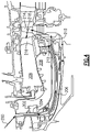
- FIG 3 shows details of the Figure 2A embodiment.
- the blade 114 is shown as having showerhead openings 145 to deliver the cooling air to the immediate front of the blade and along the blade's concave side where the hot gases leaving the vane 112 have a maximum scrubbing effect on the surface.
- the cooling airflow is also shown being delivered to the front side of the disk 199 such that the cavity there is purged with cooling air and flow recirculation of very hot gases from the turbine gaspath between the vane 112 and blade 114 is reduced in temperature to an acceptable level.
- Passages at 139 from the mixing chamber 138 allow the air to enter tubes, or a circumferentially extending chamber 142.
- FIG. 4 shows an alternative embodiment.
- the mixing chamber 138 is eliminated. Rather, the airflow 200 from the cooling compressor extends upstream of the diffuser 202 and through struts 204, and then to passages 206, passing to a TOBI 210.
- higher pressure air 212 from a rear section of the diffuser case at 208 surrounding the combustor 209 also passes to the blades 214 and vane 216 in another mixing chamber.
- showerhead cooling openings 218 deliver the air.
- the cooling compressor may be controlled as in the above embodiment.
- the control 133 may be part of a FADEC for the entire engine, or a stand-alone control programmed as appropriate.
- a gas turbine engine including a plurality of rotating components housed within a main compressor section and a turbine section.
- a first tap is connected to the main compressor section and is configured to deliver air at a first pressure.
- a heat exchanger is connected downstream of the first tap.
- a cooling air valve is configured to selectively block flow of cooling air across the heat exchanger.
- a cooling compressor is connected downstream of the heat exchanger.
- a means for stopping flow between the heat exchanger and the cooling compressor is provided.
- a second tap is configured to deliver air at a second pressure which is higher than said first pressure.
- a mixing chamber is connected downstream of the cooling compressor and the second tap. The mixing chamber is configured to deliver air to at least one of the plurality of rotating components.
- a means for stopping flow between the cooling compressor and the plurality of rotating components is provided.
- a controller is configured to modulate flow between the heat exchanger and the plurality of rotating components under certain power conditions of the gas turbine engine. The controller is programmed such that flow is stopped between the heat exchanger and the cooling compressor only after the cooling compressor has been stopped.
Landscapes
- Engineering & Computer Science (AREA)
- Chemical & Material Sciences (AREA)
- Combustion & Propulsion (AREA)
- Mechanical Engineering (AREA)
- General Engineering & Computer Science (AREA)
- Structures Of Non-Positive Displacement Pumps (AREA)
Claims (12)
- Moteur à turbine à gaz (20) comprenant :une pluralité de composants rotatifs logés à l'intérieur d'une section de compresseur principale (106) et d'une section de turbine (112/114) ;un premier robinet (118) connecté à ladite section de compresseur principale (106) et configuré pour fournir de l'air à une première pression ;un échangeur thermique (124) connecté en aval dudit premier robinet (118) ;une vanne d'air de refroidissement (152) configurée pour bloquer sélectivement l'écoulement d'air de refroidissement de dérivation à travers l'échangeur thermique (124) ;un compresseur de refroidissement (134) connecté en aval dudit échangeur thermique (124) ;un premier moyen (132) d'arrêt d'écoulement entre l'échangeur thermique (124) et le compresseur de refroidissement (134) ;un second robinet (161) configuré pour fournir de l'air à une seconde pression supérieure à ladite première pression ;une chambre de mélange (138) connectée en aval dudit compresseur de refroidissement (134) et dudit second robinet (161), dans lequel ladite chambre de mélange (138) est configurée pour fournir de l'air à au moins l'un de ladite pluralité de composants rotatifs ;un second moyen (146) pour arrêter l'écoulement entre le compresseur de refroidissement (134) et la pluralité de composants rotatifs en arrêtant la rotation du compresseur de refroidissement (134) ; etun dispositif de commande (133) configuré pour moduler l'écoulement entre l'échangeur thermique (124) et la pluralité de composants rotatifs dans certaines conditions de puissance du moteur à turbine à gaz (20) ;caractérisé en ce que :
ledit dispositif de commande (133) est programmé de sorte que l'écoulement est arrêté entre l'échangeur thermique (124) et le compresseur de refroidissement (134) uniquement après l'arrêt du compresseur de refroidissement (134). - Moteur à turbine à gaz (20) selon la revendication 1, dans lequel ledit premier moyen comporte une vanne d'arrêt (132).
- Moteur à turbine à gaz (20) selon la revendication 2, dans lequel ledit dispositif de commande (133) est programmé pour commander ladite vanne d'air de refroidissement (152), ladite vanne d'arrêt (132) et ledit second moyen (146) de sorte que l'écoulement est arrêté entre l'échangeur thermique (124) et le compresseur de refroidissement (134) uniquement après l'arrêt du compresseur de refroidissement (134).
- Moteur à turbine à gaz (20) selon la revendication 1, 2 ou 3, dans lequel ledit second moyen comporte un embrayage (146).
- Moteur à turbine à gaz (20) selon une quelconque revendication précédente, configuré de sorte que l'air en aval du compresseur de refroidissement (134) passe à travers des entretoises (160) dans un diffuseur (116) en aval de ladite section de compresseur principale (106).
- Moteur à turbine à gaz (20) selon la revendication 5, dans lequel ladite chambre de mélange (138) est radialement vers l'intérieur desdites entretoises (160).
- Moteur à turbine à gaz (20) selon une quelconque revendication précédente, dans lequel un clapet anti-retour (120) est placé sur ledit premier robinet (118) entre ladite section de compresseur principale (106) et ledit échangeur thermique (124).
- Moteur à turbine à gaz (20) selon une quelconque revendication précédente, dans lequel ledit échangeur thermique (124) est reçu dans une chambre (105) définie entre un carter central externe (102) et un carter interne (104) qui est radialement vers l'intérieur d'un conduit de dérivation.
- Moteur à turbine à gaz (20) selon la revendication 8, dans lequel ladite vanne d'air de refroidissement (152) est positionnée au niveau d'une extrémité amont de ladite chambre (105).
- Moteur à turbine à gaz (20) selon une quelconque revendication précédente, dans lequel ladite vanne d'air de refroidissement (152) est positionnée en aval dudit échangeur thermique (124).
- Moteur à turbine à gaz (20) selon une quelconque revendication précédente, dans lequel un rapport de pression de compresseur de refroidissement de l'air en aval dudit compresseur de refroidissement (134), et en amont de ladite chambre de mélange (138), par rapport à une pression d'air en aval dudit emplacement le plus en aval est supérieur ou égal à 1,02.
- Moteur à turbine à gaz (20) selon une quelconque revendication précédente, dans lequel ladite chambre de mélange (138) se trouve en amont d'une pale de turbine dans ladite section de turbine (112/114).
Applications Claiming Priority (1)
| Application Number | Priority Date | Filing Date | Title |
|---|---|---|---|
| US15/928,506 US10738703B2 (en) | 2018-03-22 | 2018-03-22 | Intercooled cooling air with combined features |
Publications (2)
| Publication Number | Publication Date |
|---|---|
| EP3543505A1 EP3543505A1 (fr) | 2019-09-25 |
| EP3543505B1 true EP3543505B1 (fr) | 2022-05-04 |
Family
ID=65991524
Family Applications (1)
| Application Number | Title | Priority Date | Filing Date |
|---|---|---|---|
| EP19164741.1A Active EP3543505B1 (fr) | 2018-03-22 | 2019-03-22 | Air de refroidissement à refroidissement intermédiaire avec des caractéristiques combinées |
Country Status (2)
| Country | Link |
|---|---|
| US (1) | US10738703B2 (fr) |
| EP (1) | EP3543505B1 (fr) |
Families Citing this family (4)
| Publication number | Priority date | Publication date | Assignee | Title |
|---|---|---|---|---|
| US11021981B2 (en) * | 2018-05-22 | 2021-06-01 | Raytheon Technologies Corporation | Downstream turbine vane cooling for a gas turbine engine |
| US11965463B2 (en) * | 2021-02-16 | 2024-04-23 | Pratt & Whitney Canada Corp. | Fluid cooler installation and method for turbofan engine |
| BE1029381B1 (fr) * | 2021-05-06 | 2022-12-05 | Safran Aero Boosters | Dispositif d'echange de chaleur et turbomachine d'aeronef avec le dispositif |
| US20250382891A1 (en) * | 2024-06-13 | 2025-12-18 | Rtx Corporation | Fan exit guide vane thermal management system for hybrid electrics |
Family Cites Families (156)
| Publication number | Priority date | Publication date | Assignee | Title |
|---|---|---|---|---|
| US2692476A (en) | 1950-11-13 | 1954-10-26 | Boeing Co | Gas turbine engine air starting motor constituting air supply mechanism |
| GB1244340A (en) | 1968-12-23 | 1971-08-25 | Rolls Royce | Front fan gas turbine engine |
| US3878677A (en) | 1974-04-10 | 1975-04-22 | United Aircraft Corp | Auxiliary turbine/compressor system for turbine engine |
| US4254618A (en) | 1977-08-18 | 1981-03-10 | General Electric Company | Cooling air cooler for a gas turbofan engine |
| JPS5477820A (en) | 1977-12-02 | 1979-06-21 | Hitachi Ltd | Method of cooling gas turbine blade |
| IT8322002U1 (it) | 1983-05-31 | 1984-12-01 | Same Spa | Gruppo motore a combustione interna con impianto di ventilazione di pompe iniezione |
| US4561246A (en) | 1983-12-23 | 1985-12-31 | United Technologies Corporation | Bearing compartment for a gas turbine engine |
| US4882902A (en) | 1986-04-30 | 1989-11-28 | General Electric Company | Turbine cooling air transferring apparatus |
| EP0447886B1 (fr) | 1990-03-23 | 1994-07-13 | Asea Brown Boveri Ag | Turbine à gaz avec flux axiale |
| US5056335A (en) | 1990-04-02 | 1991-10-15 | General Electric Company | Auxiliary refrigerated air system employing input air from turbine engine compressor after bypassing and conditioning within auxiliary system |
| US5123242A (en) | 1990-07-30 | 1992-06-23 | General Electric Company | Precooling heat exchange arrangement integral with mounting structure fairing of gas turbine engine |
| US5269135A (en) | 1991-10-28 | 1993-12-14 | General Electric Company | Gas turbine engine fan cooled heat exchanger |
| US5305616A (en) | 1992-03-23 | 1994-04-26 | General Electric Company | Gas turbine engine cooling system |
| US5392614A (en) | 1992-03-23 | 1995-02-28 | General Electric Company | Gas turbine engine cooling system |
| US5414992A (en) | 1993-08-06 | 1995-05-16 | United Technologies Corporation | Aircraft cooling method |
| US5363641A (en) * | 1993-08-06 | 1994-11-15 | United Technologies Corporation | Integrated auxiliary power system |
| US5452573A (en) | 1994-01-31 | 1995-09-26 | United Technologies Corporation | High pressure air source for aircraft and engine requirements |
| US5498126A (en) | 1994-04-28 | 1996-03-12 | United Technologies Corporation | Airfoil with dual source cooling |
| DE19531562A1 (de) | 1995-08-28 | 1997-03-06 | Abb Management Ag | Verfahren zum Betrieb einer Kraftwerksanlage |
| US5724806A (en) | 1995-09-11 | 1998-03-10 | General Electric Company | Extracted, cooled, compressed/intercooled, cooling/combustion air for a gas turbine engine |
| GB9606546D0 (en) | 1996-03-28 | 1996-06-05 | Rolls Royce Plc | Gas turbine engine system |
| US5918458A (en) | 1997-02-14 | 1999-07-06 | General Electric Company | System and method of providing clean filtered cooling air to a hot portion of a gas turbine engine |
| US5967461A (en) * | 1997-07-02 | 1999-10-19 | Mcdonnell Douglas Corp. | High efficiency environmental control systems and methods |
| JP2941748B2 (ja) | 1997-07-15 | 1999-08-30 | 三菱重工業株式会社 | ガスタービン冷却装置 |
| JPH1193694A (ja) | 1997-09-18 | 1999-04-06 | Toshiba Corp | ガスタービンプラント |
| US6430931B1 (en) | 1997-10-22 | 2002-08-13 | General Electric Company | Gas turbine in-line intercooler |
| US6065282A (en) | 1997-10-29 | 2000-05-23 | Mitsubishi Heavy Industries, Ltd. | System for cooling blades in a gas turbine |
| US6050079A (en) | 1997-12-24 | 2000-04-18 | General Electric Company | Modulated turbine cooling system |
| US6134880A (en) * | 1997-12-31 | 2000-10-24 | Concepts Eti, Inc. | Turbine engine with intercooler in bypass air passage |
| US6792762B1 (en) | 1999-11-10 | 2004-09-21 | Hitachi, Ltd. | Gas turbine equipment and gas turbine cooling method |
| DE10001112A1 (de) | 2000-01-13 | 2001-07-19 | Alstom Power Schweiz Ag Baden | Kühlluftkühler für eine Gasturbinenanlage sowie Verwendung eines solchen Kühlluftkühlers |
| DE10009655C1 (de) | 2000-02-29 | 2001-05-23 | Mtu Aero Engines Gmbh | Kühlluftsystem |
| US6487863B1 (en) | 2001-03-30 | 2002-12-03 | Siemens Westinghouse Power Corporation | Method and apparatus for cooling high temperature components in a gas turbine |
| DE10122695A1 (de) | 2001-05-10 | 2002-11-21 | Siemens Ag | Verfahren zur Kühlung einer Gasturbine und Gasturbinenanlage |
| JP3849473B2 (ja) | 2001-08-29 | 2006-11-22 | 株式会社日立製作所 | ガスタービンの高温部冷却方法 |
| US6550253B2 (en) | 2001-09-12 | 2003-04-22 | General Electric Company | Apparatus and methods for controlling flow in turbomachinery |
| US6651929B2 (en) | 2001-10-29 | 2003-11-25 | Pratt & Whitney Canada Corp. | Passive cooling system for auxiliary power unit installation |
| US6523346B1 (en) | 2001-11-02 | 2003-02-25 | Alstom (Switzerland) Ltd | Process for controlling the cooling air mass flow of a gas turbine set |
| US8037686B2 (en) | 2002-11-01 | 2011-10-18 | George Lasker | Uncoupled, thermal-compressor, gas-turbine engine |
| EP1418319A1 (fr) | 2002-11-11 | 2004-05-12 | Siemens Aktiengesellschaft | Turbine à Gaz |
| FR2851295B1 (fr) | 2003-02-19 | 2006-06-23 | Snecma Moteurs | Systeme de prelevement d'air d'un turboreacteur |
| EP1508747A1 (fr) | 2003-08-18 | 2005-02-23 | Siemens Aktiengesellschaft | Diffuseur de turbine à gaz et turbine à gaz pour la production d'énergie |
| US7246484B2 (en) | 2003-08-25 | 2007-07-24 | General Electric Company | FLADE gas turbine engine with counter-rotatable fans |
| US7347637B2 (en) | 2003-09-04 | 2008-03-25 | Sharp Kabushiki Kaisha | Hybrid paper supply module and image forming apparatus equipped with such hybrid paper supply module |
| US20070199331A1 (en) | 2003-09-19 | 2007-08-30 | Maguire Alan R | Power transmission arrangement |
| US7284377B2 (en) | 2004-05-28 | 2007-10-23 | General Electric Company | Method and apparatus for operating an intercooler for a gas turbine engine |
| US7306424B2 (en) | 2004-12-29 | 2007-12-11 | United Technologies Corporation | Blade outer seal with micro axial flow cooling system |
| FR2882096B1 (fr) | 2005-02-11 | 2012-04-20 | Snecma Moteurs | Turbomoteur a double corps avec des moyens de prise de mouvement sur les rotors basse pression et haute pression, module de prise de mouvement pour le turbomoteur et procede de montage du turbomoteur |
| US7500365B2 (en) | 2005-05-05 | 2009-03-10 | United Technologies Corporation | Accessory gearbox |
| FR2889250B1 (fr) | 2005-07-28 | 2007-09-07 | Airbus France Sas | Ensemble propulseur pour aeronef et aeronef comportant au moins un tel ensemble propulseur |
| US20070022735A1 (en) | 2005-07-29 | 2007-02-01 | General Electric Company | Pto assembly for a gas turbine engine |
| FR2891313A1 (fr) * | 2005-09-26 | 2007-03-30 | Airbus France Sas | Turbomoteur a double flux pourvu d'un prerefroidisseur |
| FR2896276B1 (fr) | 2006-01-19 | 2008-02-15 | Airbus France Sas | Turbomoteur a double flux pourvu d'un prerefroidisseur. |
| US7532969B2 (en) | 2006-03-09 | 2009-05-12 | Pratt & Whitney Canada Corp. | Gas turbine speed detection |
| GB0607773D0 (en) | 2006-04-20 | 2006-05-31 | Rolls Royce Plc | A gas turbine engine |
| GB0607771D0 (en) | 2006-04-20 | 2006-05-31 | Rolls Royce Plc | A heat exchanger arrangement |
| US8776952B2 (en) | 2006-05-11 | 2014-07-15 | United Technologies Corporation | Thermal management system for turbofan engines |
| US7765788B2 (en) | 2006-07-06 | 2010-08-03 | United Technologies Corporation | Cooling exchanger duct |
| US20080028763A1 (en) | 2006-08-03 | 2008-02-07 | United Technologies Corporation | Thermal management system with thrust recovery for a gas turbine engine fan nacelle assembly |
| GB0617769D0 (en) | 2006-09-09 | 2006-10-18 | Rolls Royce Plc | An engine |
| US7823389B2 (en) * | 2006-11-15 | 2010-11-02 | General Electric Company | Compound clearance control engine |
| WO2008082335A1 (fr) | 2006-12-29 | 2008-07-10 | Volvo Aero Corporation | Dispositif de transmission de puissance pour une turbine à gaz |
| EP1944475B1 (fr) | 2007-01-08 | 2015-08-12 | United Technologies Corporation | Système d'échange de chaleur |
| US8015828B2 (en) | 2007-04-03 | 2011-09-13 | General Electric Company | Power take-off system and gas turbine engine assembly including same |
| US7882691B2 (en) | 2007-07-05 | 2011-02-08 | Hamilton Sundstrand Corporation | High to low pressure spool summing gearbox for accessory power extraction and electric start |
| US8434997B2 (en) | 2007-08-22 | 2013-05-07 | United Technologies Corporation | Gas turbine engine case for clearance control |
| US8205432B2 (en) | 2007-10-03 | 2012-06-26 | United Technologies Corporation | Epicyclic gear train for turbo fan engine |
| US8104289B2 (en) | 2007-10-09 | 2012-01-31 | United Technologies Corp. | Systems and methods involving multiple torque paths for gas turbine engines |
| US8402742B2 (en) | 2007-12-05 | 2013-03-26 | United Technologies Corporation | Gas turbine engine systems involving tip fans |
| US8590286B2 (en) | 2007-12-05 | 2013-11-26 | United Technologies Corp. | Gas turbine engine systems involving tip fans |
| US9234481B2 (en) | 2008-01-25 | 2016-01-12 | United Technologies Corporation | Shared flow thermal management system |
| US8096747B2 (en) * | 2008-02-01 | 2012-01-17 | General Electric Company | Apparatus and related methods for turbine cooling |
| JP5092143B2 (ja) | 2008-03-07 | 2012-12-05 | 独立行政法人 宇宙航空研究開発機構 | 高バイパス比ターボファンジェットエンジン |
| US8192143B2 (en) | 2008-05-21 | 2012-06-05 | United Technologies Corporation | Gearbox assembly |
| EP2128023B1 (fr) | 2008-05-29 | 2012-05-23 | Pratt & Whitney Canada Corp. | Un moteur à turbine à gaz comprenant un ensemble refroidisseur |
| JP5297114B2 (ja) | 2008-08-06 | 2013-09-25 | 三菱重工業株式会社 | ガスタービン |
| US8266889B2 (en) | 2008-08-25 | 2012-09-18 | General Electric Company | Gas turbine engine fan bleed heat exchanger system |
| GB0821684D0 (en) | 2008-11-28 | 2008-12-31 | Rolls Royce Plc | Aeroengine starter/generator arrangement |
| US8181443B2 (en) | 2008-12-10 | 2012-05-22 | Pratt & Whitney Canada Corp. | Heat exchanger to cool turbine air cooling flow |
| US8087249B2 (en) | 2008-12-23 | 2012-01-03 | General Electric Company | Turbine cooling air from a centrifugal compressor |
| US9885313B2 (en) | 2009-03-17 | 2018-02-06 | United Technologes Corporation | Gas turbine engine bifurcation located fan variable area nozzle |
| US9014791B2 (en) | 2009-04-17 | 2015-04-21 | Echogen Power Systems, Llc | System and method for managing thermal issues in gas turbine engines |
| DE102009021384A1 (de) | 2009-05-14 | 2010-11-18 | Mtu Aero Engines Gmbh | Strömungsvorrichtung mit Kavitätenkühlung |
| US8516786B2 (en) | 2009-08-13 | 2013-08-27 | General Electric Company | System and method for injection of cooling air into exhaust gas flow |
| US8307662B2 (en) | 2009-10-15 | 2012-11-13 | General Electric Company | Gas turbine engine temperature modulated cooling flow |
| US20110120083A1 (en) | 2009-11-20 | 2011-05-26 | Rollin George Giffin | Gas turbine engine with outer fans |
| US8516828B2 (en) | 2010-02-19 | 2013-08-27 | United Technologies Corporation | Bearing compartment pressurization and shaft ventilation system |
| WO2011162845A1 (fr) | 2010-03-26 | 2011-12-29 | Rolls-Royce North American Technologies, Inc. | Système de soufflante adaptative pour moteur à double flux à cycle variable |
| US8256229B2 (en) | 2010-04-09 | 2012-09-04 | United Technologies Corporation | Rear hub cooling for high pressure compressor |
| GB201007063D0 (en) | 2010-04-28 | 2010-06-09 | Rolls Royce Plc | A gas turbine engine |
| US8727703B2 (en) | 2010-09-07 | 2014-05-20 | Siemens Energy, Inc. | Gas turbine engine |
| US8602717B2 (en) | 2010-10-28 | 2013-12-10 | United Technologies Corporation | Compression system for turbomachine heat exchanger |
| US9410482B2 (en) | 2010-12-24 | 2016-08-09 | Rolls-Royce North American Technologies, Inc. | Gas turbine engine heat exchanger |
| US9062604B2 (en) | 2011-01-14 | 2015-06-23 | Hamilton Sundstrand Corporation | Low pressure bleed architecture |
| US8397487B2 (en) | 2011-02-28 | 2013-03-19 | General Electric Company | Environmental control system supply precooler bypass |
| US8814502B2 (en) | 2011-05-31 | 2014-08-26 | Pratt & Whitney Canada Corp. | Dual input drive AGB for gas turbine engines |
| CH705181A1 (de) | 2011-06-16 | 2012-12-31 | Alstom Technology Ltd | Verfahren zum Kühlen einer Gasturbinenanlage sowie Gasturbinenanlage zur Durchführung des Verfahrens. |
| US9200592B2 (en) | 2011-06-28 | 2015-12-01 | United Technologies Corporation | Mechanism for turbine engine start from low spool |
| US20130040545A1 (en) | 2011-08-11 | 2013-02-14 | Hamilton Sundstrand Corporation | Low pressure compressor bleed exit for an aircraft pressurization system |
| EP2562369B1 (fr) | 2011-08-22 | 2015-01-14 | Alstom Technology Ltd | Méthode pour opérer une turbine à gaz et turbine à gaz pour exécuter la méthode |
| US8978352B2 (en) | 2011-10-21 | 2015-03-17 | United Technologies Corporation | Apparatus and method for operating a gas turbine engine during windmilling |
| US8966875B2 (en) | 2011-10-21 | 2015-03-03 | United Technologies Corporation | Constant speed transmission for gas turbine engine |
| US9068515B2 (en) | 2011-12-07 | 2015-06-30 | United Technologies Corporation | Accessory gearbox with tower shaft removal capability |
| US9045998B2 (en) | 2011-12-12 | 2015-06-02 | Honeywell International Inc. | System for directing air flow to a plurality of plena |
| GB201121428D0 (en) | 2011-12-14 | 2012-01-25 | Rolls Royce Plc | Controller |
| GB201121426D0 (en) | 2011-12-14 | 2012-01-25 | Rolls Royce Plc | Controller |
| US8955794B2 (en) | 2012-01-24 | 2015-02-17 | The Boeing Company | Bleed air systems for use with aircrafts and related methods |
| US9243563B2 (en) * | 2012-01-25 | 2016-01-26 | Honeywell International Inc. | Gas turbine engine in-board cooled cooling air system |
| US10018116B2 (en) | 2012-01-31 | 2018-07-10 | United Technologies Corporation | Gas turbine engine buffer system providing zoned ventilation |
| US9394803B2 (en) | 2012-03-14 | 2016-07-19 | United Technologies Corporation | Bypass air-pump system within the core engine to provide air for an environmental control system in a gas turbine engine |
| US8961108B2 (en) | 2012-04-04 | 2015-02-24 | United Technologies Corporation | Cooling system for a turbine vane |
| US9249731B2 (en) | 2012-06-05 | 2016-02-02 | United Technologies Corporation | Nacelle bifurcation for gas turbine engine |
| US8973465B2 (en) | 2012-07-20 | 2015-03-10 | United Technologies Corporation | Gearbox for gas turbine engine |
| WO2014046713A1 (fr) | 2012-09-20 | 2014-03-27 | United Technologies Corporation | Boîte d'engrenages d'accessoire de moteur à turbine à gaz à réducteur |
| EP3770415B1 (fr) | 2012-10-02 | 2026-05-06 | RTX Corporation | Turboréacteur double-flux à engrenages présentant une température de sortie de compresseur élevée |
| ITBO20120626A1 (it) | 2012-11-15 | 2014-05-16 | Magneti Marelli Spa | Scambiatore di calore con recupero di energia termica per un sistema di scarico di un motore a combustione interna |
| US9622620B2 (en) | 2012-11-19 | 2017-04-18 | Helen Of Troy Limited | Device for cutting small food items |
| US10247097B2 (en) | 2012-12-10 | 2019-04-02 | United Technologies Corporation | Gas turbine engine with plural accessory air paths |
| US9562475B2 (en) | 2012-12-19 | 2017-02-07 | Siemens Aktiengesellschaft | Vane carrier temperature control system in a gas turbine engine |
| US10094286B2 (en) | 2013-01-29 | 2018-10-09 | United Technologies Corporation | Gas turbine engine with lower bifurcation heat exchanger |
| CN203441604U (zh) | 2013-02-15 | 2014-02-19 | 通用电气公司 | 用于降低燃气涡轮系统中的背压的系统 |
| WO2014134519A1 (fr) | 2013-02-28 | 2014-09-04 | United Technologies Corporation | Procédé et appareil pour capter un écoulement d'air de pré-diffuseur et l'acheminer vers des pré-unités de turbulence de chambre à combustion |
| GB201308788D0 (en) * | 2013-05-16 | 2013-06-26 | Rolls Royce Plc | Heat exchange arrangement |
| US9429072B2 (en) | 2013-05-22 | 2016-08-30 | General Electric Company | Return fluid air cooler system for turbine cooling with optional power extraction |
| US9422063B2 (en) | 2013-05-31 | 2016-08-23 | General Electric Company | Cooled cooling air system for a gas turbine |
| WO2015009449A1 (fr) * | 2013-07-17 | 2015-01-22 | United Technologies Corporation | Conduit d'alimentation en air de refroidissement |
| EP3049641A4 (fr) | 2013-09-24 | 2017-06-28 | United Technologies Corporation | Placement d'échangeur de chaleur à conduit de dérivation |
| US9764435B2 (en) | 2013-10-28 | 2017-09-19 | Honeywell International Inc. | Counter-flow heat exchange systems |
| US10253632B2 (en) | 2013-12-30 | 2019-04-09 | United Technologies Corporation | Compressor rim thermal management |
| JP6296286B2 (ja) | 2014-03-24 | 2018-03-20 | 三菱日立パワーシステムズ株式会社 | 排熱回収システム、これを備えているガスタービンプラント、排熱回収方法、及び排熱回収システムの追設方法 |
| US9810158B2 (en) * | 2014-04-01 | 2017-11-07 | The Boeing Company | Bleed air systems for use with aircraft and related methods |
| US10024238B2 (en) * | 2014-04-03 | 2018-07-17 | United Technologies Corporation | Cooling system with a bearing compartment bypass |
| US20170328231A1 (en) | 2014-05-09 | 2017-11-16 | United Technologies Corporation | Turbine clearance control system and method for improved variable cycle gas turbine engine fuel burn |
| GB201408415D0 (en) | 2014-05-13 | 2014-06-25 | Rolls Royce Plc | Bifurcation fairing |
| US20150354465A1 (en) | 2014-06-06 | 2015-12-10 | United Technologies Corporation | Turbine stage cooling |
| US10018360B2 (en) | 2014-06-06 | 2018-07-10 | United Technologies Corporation | Turbine stage cooling |
| EP3018304B1 (fr) | 2014-11-06 | 2020-10-14 | United Technologies Corporation | Système de gestion thermique pour moteur à turbine à gaz |
| US20160169118A1 (en) | 2014-12-12 | 2016-06-16 | United Technologies Corporation | Dual tower shaft gearbox for gas turbine engine |
| US10443501B2 (en) | 2015-02-05 | 2019-10-15 | Powerphase Llc | Turbocooled vane of a gas turbine engine |
| US10006370B2 (en) * | 2015-02-12 | 2018-06-26 | United Technologies Corporation | Intercooled cooling air with heat exchanger packaging |
| US9856793B2 (en) * | 2015-02-12 | 2018-01-02 | United Technologies Corporation | Intercooled cooling air with improved air flow |
| US9850819B2 (en) | 2015-04-24 | 2017-12-26 | United Technologies Corporation | Intercooled cooling air with dual pass heat exchanger |
| US10221862B2 (en) * | 2015-04-24 | 2019-03-05 | United Technologies Corporation | Intercooled cooling air tapped from plural locations |
| US20160369697A1 (en) | 2015-06-16 | 2016-12-22 | United Technologies Corporation | Cooled cooling air system for a turbofan engine |
| EP3109436B1 (fr) | 2015-06-22 | 2020-02-26 | United Technologies Corporation | Turbomachine avec air de refroidissement refroidi à écoulement d'air amélioré |
| US10794288B2 (en) * | 2015-07-07 | 2020-10-06 | Raytheon Technologies Corporation | Cooled cooling air system for a turbofan engine |
| EP3121411B1 (fr) | 2015-07-21 | 2018-12-12 | United Technologies Corporation | Air de refroidissement refroidi par échangeur de chaleur existant |
| US10253695B2 (en) | 2015-08-14 | 2019-04-09 | United Technologies Corporation | Heat exchanger for cooled cooling air with adjustable damper |
| US10060353B2 (en) | 2015-08-14 | 2018-08-28 | United Technologies Corporation | Heat exchanger for cooled cooling air |
| US20170159568A1 (en) | 2015-12-03 | 2017-06-08 | General Electric Company | Intercooling system and method for a gas turbine engine |
| US10443508B2 (en) * | 2015-12-14 | 2019-10-15 | United Technologies Corporation | Intercooled cooling air with auxiliary compressor control |
| US10364749B2 (en) * | 2015-12-18 | 2019-07-30 | United Technologies Corporation | Cooling air heat exchanger scoop |
| US20170184027A1 (en) * | 2015-12-29 | 2017-06-29 | General Electric Company | Method and system for compressor and turbine cooling |
| US10563582B2 (en) | 2016-01-19 | 2020-02-18 | United Technologies Corporation | Heat exchanger array |
| US10526916B2 (en) * | 2016-04-26 | 2020-01-07 | United Technologies Corporation | Heat exchanger with heat resistant center body |
| US10669940B2 (en) | 2016-09-19 | 2020-06-02 | Raytheon Technologies Corporation | Gas turbine engine with intercooled cooling air and turbine drive |
-
2018
- 2018-03-22 US US15/928,506 patent/US10738703B2/en active Active
-
2019
- 2019-03-22 EP EP19164741.1A patent/EP3543505B1/fr active Active
Also Published As
| Publication number | Publication date |
|---|---|
| EP3543505A1 (fr) | 2019-09-25 |
| US10738703B2 (en) | 2020-08-11 |
| US20190292985A1 (en) | 2019-09-26 |
Similar Documents
| Publication | Publication Date | Title |
|---|---|---|
| US11236675B2 (en) | Gas turbine engine with intercooled cooling air and turbine drive | |
| EP3584427B1 (fr) | Système à air de refroidissement refroidi avec de l'air à basse température pour compartiment de palier | |
| EP2807357B1 (fr) | Echangeur thermique | |
| EP3369911B1 (fr) | Bouclier thermique pour boîtier de diffuseur de moteur à turbine à gaz | |
| EP3543505B1 (fr) | Air de refroidissement à refroidissement intermédiaire avec des caractéristiques combinées | |
| US11773742B2 (en) | Cooled cooling air for blade air seal through outer chamber | |
| EP3792473B1 (fr) | Air de refroidissement refroidi par carburant | |
| US20170254219A1 (en) | Firewall mount hub | |
| EP3330515B1 (fr) | Moteur à turbine à gaz | |
| EP3572645B1 (fr) | Refroidissement amélioré d'aube de turbine en aval pour un moteur à turbine à gaz | |
| EP3388637B1 (fr) | Chambre d'air de refroidissement pour joint d'air extérieur d'aube | |
| EP3388625B1 (fr) | Air de refroidissement refroidi vers un joint d'air extérieur d'aubes à travers une aube de stator | |
| EP3557030B1 (fr) | Air de refroidissement refroidi par système de refroidissement avancé | |
| EP4144971B1 (fr) | Air de refroidissement refroidi avec décharge de pression sélective | |
| EP3358152B1 (fr) | Chambre de mélange externe pour moteur à turbine à gaz avec de l'air de refroidissement de turbine refroidi | |
| EP3348812B1 (fr) | Air de refroidissement de moteur à turbine à gaz avec décharge d'air froid |
Legal Events
| Date | Code | Title | Description |
|---|---|---|---|
| PUAI | Public reference made under article 153(3) epc to a published international application that has entered the european phase |
Free format text: ORIGINAL CODE: 0009012 |
|
| STAA | Information on the status of an ep patent application or granted ep patent |
Free format text: STATUS: THE APPLICATION HAS BEEN PUBLISHED |
|
| AK | Designated contracting states |
Kind code of ref document: A1 Designated state(s): AL AT BE BG CH CY CZ DE DK EE ES FI FR GB GR HR HU IE IS IT LI LT LU LV MC MK MT NL NO PL PT RO RS SE SI SK SM TR |
|
| AX | Request for extension of the european patent |
Extension state: BA ME |
|
| STAA | Information on the status of an ep patent application or granted ep patent |
Free format text: STATUS: REQUEST FOR EXAMINATION WAS MADE |
|
| 17P | Request for examination filed |
Effective date: 20200325 |
|
| RBV | Designated contracting states (corrected) |
Designated state(s): AL AT BE BG CH CY CZ DE DK EE ES FI FR GB GR HR HU IE IS IT LI LT LU LV MC MK MT NL NO PL PT RO RS SE SI SK SM TR |
|
| RAP1 | Party data changed (applicant data changed or rights of an application transferred) |
Owner name: RAYTHEON TECHNOLOGIES CORPORATION |
|
| GRAP | Despatch of communication of intention to grant a patent |
Free format text: ORIGINAL CODE: EPIDOSNIGR1 |
|
| STAA | Information on the status of an ep patent application or granted ep patent |
Free format text: STATUS: GRANT OF PATENT IS INTENDED |
|
| INTG | Intention to grant announced |
Effective date: 20211203 |
|
| GRAS | Grant fee paid |
Free format text: ORIGINAL CODE: EPIDOSNIGR3 |
|
| GRAA | (expected) grant |
Free format text: ORIGINAL CODE: 0009210 |
|
| STAA | Information on the status of an ep patent application or granted ep patent |
Free format text: STATUS: THE PATENT HAS BEEN GRANTED |
|
| AK | Designated contracting states |
Kind code of ref document: B1 Designated state(s): AL AT BE BG CH CY CZ DE DK EE ES FI FR GB GR HR HU IE IS IT LI LT LU LV MC MK MT NL NO PL PT RO RS SE SI SK SM TR |
|
| REG | Reference to a national code |
Ref country code: GB Ref legal event code: FG4D |
|
| REG | Reference to a national code |
Ref country code: CH Ref legal event code: EP |
|
| REG | Reference to a national code |
Ref country code: AT Ref legal event code: REF Ref document number: 1489257 Country of ref document: AT Kind code of ref document: T Effective date: 20220515 |
|
| REG | Reference to a national code |
Ref country code: DE Ref legal event code: R096 Ref document number: 602019014324 Country of ref document: DE |
|
| REG | Reference to a national code |
Ref country code: IE Ref legal event code: FG4D |
|
| REG | Reference to a national code |
Ref country code: LT Ref legal event code: MG9D |
|
| REG | Reference to a national code |
Ref country code: NL Ref legal event code: MP Effective date: 20220504 |
|
| REG | Reference to a national code |
Ref country code: AT Ref legal event code: MK05 Ref document number: 1489257 Country of ref document: AT Kind code of ref document: T Effective date: 20220504 |
|
| PG25 | Lapsed in a contracting state [announced via postgrant information from national office to epo] |
Ref country code: SE Free format text: LAPSE BECAUSE OF FAILURE TO SUBMIT A TRANSLATION OF THE DESCRIPTION OR TO PAY THE FEE WITHIN THE PRESCRIBED TIME-LIMIT Effective date: 20220504 Ref country code: PT Free format text: LAPSE BECAUSE OF FAILURE TO SUBMIT A TRANSLATION OF THE DESCRIPTION OR TO PAY THE FEE WITHIN THE PRESCRIBED TIME-LIMIT Effective date: 20220905 Ref country code: NO Free format text: LAPSE BECAUSE OF FAILURE TO SUBMIT A TRANSLATION OF THE DESCRIPTION OR TO PAY THE FEE WITHIN THE PRESCRIBED TIME-LIMIT Effective date: 20220804 Ref country code: NL Free format text: LAPSE BECAUSE OF FAILURE TO SUBMIT A TRANSLATION OF THE DESCRIPTION OR TO PAY THE FEE WITHIN THE PRESCRIBED TIME-LIMIT Effective date: 20220504 Ref country code: LT Free format text: LAPSE BECAUSE OF FAILURE TO SUBMIT A TRANSLATION OF THE DESCRIPTION OR TO PAY THE FEE WITHIN THE PRESCRIBED TIME-LIMIT Effective date: 20220504 Ref country code: HR Free format text: LAPSE BECAUSE OF FAILURE TO SUBMIT A TRANSLATION OF THE DESCRIPTION OR TO PAY THE FEE WITHIN THE PRESCRIBED TIME-LIMIT Effective date: 20220504 Ref country code: GR Free format text: LAPSE BECAUSE OF FAILURE TO SUBMIT A TRANSLATION OF THE DESCRIPTION OR TO PAY THE FEE WITHIN THE PRESCRIBED TIME-LIMIT Effective date: 20220805 Ref country code: FI Free format text: LAPSE BECAUSE OF FAILURE TO SUBMIT A TRANSLATION OF THE DESCRIPTION OR TO PAY THE FEE WITHIN THE PRESCRIBED TIME-LIMIT Effective date: 20220504 Ref country code: ES Free format text: LAPSE BECAUSE OF FAILURE TO SUBMIT A TRANSLATION OF THE DESCRIPTION OR TO PAY THE FEE WITHIN THE PRESCRIBED TIME-LIMIT Effective date: 20220504 Ref country code: BG Free format text: LAPSE BECAUSE OF FAILURE TO SUBMIT A TRANSLATION OF THE DESCRIPTION OR TO PAY THE FEE WITHIN THE PRESCRIBED TIME-LIMIT Effective date: 20220804 Ref country code: AT Free format text: LAPSE BECAUSE OF FAILURE TO SUBMIT A TRANSLATION OF THE DESCRIPTION OR TO PAY THE FEE WITHIN THE PRESCRIBED TIME-LIMIT Effective date: 20220504 |
|
| PG25 | Lapsed in a contracting state [announced via postgrant information from national office to epo] |
Ref country code: RS Free format text: LAPSE BECAUSE OF FAILURE TO SUBMIT A TRANSLATION OF THE DESCRIPTION OR TO PAY THE FEE WITHIN THE PRESCRIBED TIME-LIMIT Effective date: 20220504 Ref country code: PL Free format text: LAPSE BECAUSE OF FAILURE TO SUBMIT A TRANSLATION OF THE DESCRIPTION OR TO PAY THE FEE WITHIN THE PRESCRIBED TIME-LIMIT Effective date: 20220504 Ref country code: LV Free format text: LAPSE BECAUSE OF FAILURE TO SUBMIT A TRANSLATION OF THE DESCRIPTION OR TO PAY THE FEE WITHIN THE PRESCRIBED TIME-LIMIT Effective date: 20220504 Ref country code: IS Free format text: LAPSE BECAUSE OF FAILURE TO SUBMIT A TRANSLATION OF THE DESCRIPTION OR TO PAY THE FEE WITHIN THE PRESCRIBED TIME-LIMIT Effective date: 20220904 |
|
| PG25 | Lapsed in a contracting state [announced via postgrant information from national office to epo] |
Ref country code: SM Free format text: LAPSE BECAUSE OF FAILURE TO SUBMIT A TRANSLATION OF THE DESCRIPTION OR TO PAY THE FEE WITHIN THE PRESCRIBED TIME-LIMIT Effective date: 20220504 Ref country code: SK Free format text: LAPSE BECAUSE OF FAILURE TO SUBMIT A TRANSLATION OF THE DESCRIPTION OR TO PAY THE FEE WITHIN THE PRESCRIBED TIME-LIMIT Effective date: 20220504 Ref country code: RO Free format text: LAPSE BECAUSE OF FAILURE TO SUBMIT A TRANSLATION OF THE DESCRIPTION OR TO PAY THE FEE WITHIN THE PRESCRIBED TIME-LIMIT Effective date: 20220504 Ref country code: EE Free format text: LAPSE BECAUSE OF FAILURE TO SUBMIT A TRANSLATION OF THE DESCRIPTION OR TO PAY THE FEE WITHIN THE PRESCRIBED TIME-LIMIT Effective date: 20220504 Ref country code: DK Free format text: LAPSE BECAUSE OF FAILURE TO SUBMIT A TRANSLATION OF THE DESCRIPTION OR TO PAY THE FEE WITHIN THE PRESCRIBED TIME-LIMIT Effective date: 20220504 Ref country code: CZ Free format text: LAPSE BECAUSE OF FAILURE TO SUBMIT A TRANSLATION OF THE DESCRIPTION OR TO PAY THE FEE WITHIN THE PRESCRIBED TIME-LIMIT Effective date: 20220504 |
|
| REG | Reference to a national code |
Ref country code: DE Ref legal event code: R097 Ref document number: 602019014324 Country of ref document: DE |
|
| PLBE | No opposition filed within time limit |
Free format text: ORIGINAL CODE: 0009261 |
|
| STAA | Information on the status of an ep patent application or granted ep patent |
Free format text: STATUS: NO OPPOSITION FILED WITHIN TIME LIMIT |
|
| PG25 | Lapsed in a contracting state [announced via postgrant information from national office to epo] |
Ref country code: AL Free format text: LAPSE BECAUSE OF FAILURE TO SUBMIT A TRANSLATION OF THE DESCRIPTION OR TO PAY THE FEE WITHIN THE PRESCRIBED TIME-LIMIT Effective date: 20220504 |
|
| 26N | No opposition filed |
Effective date: 20230207 |
|
| PG25 | Lapsed in a contracting state [announced via postgrant information from national office to epo] |
Ref country code: SI Free format text: LAPSE BECAUSE OF FAILURE TO SUBMIT A TRANSLATION OF THE DESCRIPTION OR TO PAY THE FEE WITHIN THE PRESCRIBED TIME-LIMIT Effective date: 20220504 |
|
| P01 | Opt-out of the competence of the unified patent court (upc) registered |
Effective date: 20230521 |
|
| PG25 | Lapsed in a contracting state [announced via postgrant information from national office to epo] |
Ref country code: MC Free format text: LAPSE BECAUSE OF FAILURE TO SUBMIT A TRANSLATION OF THE DESCRIPTION OR TO PAY THE FEE WITHIN THE PRESCRIBED TIME-LIMIT Effective date: 20220504 |
|
| REG | Reference to a national code |
Ref country code: CH Ref legal event code: PL |
|
| REG | Reference to a national code |
Ref country code: BE Ref legal event code: MM Effective date: 20230331 |
|
| PG25 | Lapsed in a contracting state [announced via postgrant information from national office to epo] |
Ref country code: LU Free format text: LAPSE BECAUSE OF NON-PAYMENT OF DUE FEES Effective date: 20230322 |
|
| REG | Reference to a national code |
Ref country code: IE Ref legal event code: MM4A |
|
| PG25 | Lapsed in a contracting state [announced via postgrant information from national office to epo] |
Ref country code: LI Free format text: LAPSE BECAUSE OF NON-PAYMENT OF DUE FEES Effective date: 20230331 Ref country code: IT Free format text: LAPSE BECAUSE OF FAILURE TO SUBMIT A TRANSLATION OF THE DESCRIPTION OR TO PAY THE FEE WITHIN THE PRESCRIBED TIME-LIMIT Effective date: 20220504 Ref country code: IE Free format text: LAPSE BECAUSE OF NON-PAYMENT OF DUE FEES Effective date: 20230322 Ref country code: CH Free format text: LAPSE BECAUSE OF NON-PAYMENT OF DUE FEES Effective date: 20230331 |
|
| PG25 | Lapsed in a contracting state [announced via postgrant information from national office to epo] |
Ref country code: BE Free format text: LAPSE BECAUSE OF NON-PAYMENT OF DUE FEES Effective date: 20230331 |
|
| PG25 | Lapsed in a contracting state [announced via postgrant information from national office to epo] |
Ref country code: BG Free format text: LAPSE BECAUSE OF FAILURE TO SUBMIT A TRANSLATION OF THE DESCRIPTION OR TO PAY THE FEE WITHIN THE PRESCRIBED TIME-LIMIT Effective date: 20220504 |
|
| PG25 | Lapsed in a contracting state [announced via postgrant information from national office to epo] |
Ref country code: BG Free format text: LAPSE BECAUSE OF FAILURE TO SUBMIT A TRANSLATION OF THE DESCRIPTION OR TO PAY THE FEE WITHIN THE PRESCRIBED TIME-LIMIT Effective date: 20220504 |
|
| PG25 | Lapsed in a contracting state [announced via postgrant information from national office to epo] |
Ref country code: CY Free format text: LAPSE BECAUSE OF FAILURE TO SUBMIT A TRANSLATION OF THE DESCRIPTION OR TO PAY THE FEE WITHIN THE PRESCRIBED TIME-LIMIT; INVALID AB INITIO Effective date: 20190322 |
|
| PG25 | Lapsed in a contracting state [announced via postgrant information from national office to epo] |
Ref country code: HU Free format text: LAPSE BECAUSE OF FAILURE TO SUBMIT A TRANSLATION OF THE DESCRIPTION OR TO PAY THE FEE WITHIN THE PRESCRIBED TIME-LIMIT; INVALID AB INITIO Effective date: 20190322 |
|
| REG | Reference to a national code |
Ref country code: DE Ref legal event code: R081 Ref document number: 602019014324 Country of ref document: DE Owner name: RTX CORPORATION (N.D.GES.D. STAATES DELAWARE),, US Free format text: FORMER OWNER: RAYTHEON TECHNOLOGIES CORPORATION, FARMINGTON, CT, US |
|
| PG25 | Lapsed in a contracting state [announced via postgrant information from national office to epo] |
Ref country code: TR Free format text: LAPSE BECAUSE OF FAILURE TO SUBMIT A TRANSLATION OF THE DESCRIPTION OR TO PAY THE FEE WITHIN THE PRESCRIBED TIME-LIMIT Effective date: 20220504 |
|
| PGFP | Annual fee paid to national office [announced via postgrant information from national office to epo] |
Ref country code: GB Payment date: 20260219 Year of fee payment: 8 |
|
| PGFP | Annual fee paid to national office [announced via postgrant information from national office to epo] |
Ref country code: DE Payment date: 20260219 Year of fee payment: 8 |
|
| PGFP | Annual fee paid to national office [announced via postgrant information from national office to epo] |
Ref country code: FR Payment date: 20260219 Year of fee payment: 8 |