EP3543600A2 - Tige de mélange permettant de mélanger un faisceau de rayons lumineux ainsi que dispositif d'éclairage doté d'une telle tige de mélange - Google Patents
Tige de mélange permettant de mélanger un faisceau de rayons lumineux ainsi que dispositif d'éclairage doté d'une telle tige de mélange Download PDFInfo
- Publication number
- EP3543600A2 EP3543600A2 EP19164262.8A EP19164262A EP3543600A2 EP 3543600 A2 EP3543600 A2 EP 3543600A2 EP 19164262 A EP19164262 A EP 19164262A EP 3543600 A2 EP3543600 A2 EP 3543600A2
- Authority
- EP
- European Patent Office
- Prior art keywords
- light
- mixing rod
- mixing
- exit surface
- lens
- Prior art date
- Legal status (The legal status is an assumption and is not a legal conclusion. Google has not performed a legal analysis and makes no representation as to the accuracy of the status listed.)
- Granted
Links
Images

Classifications
-
- G—PHYSICS
- G02—OPTICS
- G02B—OPTICAL ELEMENTS, SYSTEMS OR APPARATUS
- G02B6/00—Light guides; Structural details of arrangements comprising light guides and other optical elements, e.g. couplings
- G02B6/0001—Light guides; Structural details of arrangements comprising light guides and other optical elements, e.g. couplings specially adapted for lighting devices or systems
- G02B6/0005—Light guides; Structural details of arrangements comprising light guides and other optical elements, e.g. couplings specially adapted for lighting devices or systems the light guides being of the fibre type
- G02B6/0008—Light guides; Structural details of arrangements comprising light guides and other optical elements, e.g. couplings specially adapted for lighting devices or systems the light guides being of the fibre type the light being emitted at the end of the fibre
-
- G—PHYSICS
- G02—OPTICS
- G02B—OPTICAL ELEMENTS, SYSTEMS OR APPARATUS
- G02B19/00—Condensers, e.g. light collectors or similar non-imaging optics
- G02B19/0004—Condensers, e.g. light collectors or similar non-imaging optics characterised by the optical means employed
- G02B19/0009—Condensers, e.g. light collectors or similar non-imaging optics characterised by the optical means employed having refractive surfaces only
- G02B19/0014—Condensers, e.g. light collectors or similar non-imaging optics characterised by the optical means employed having refractive surfaces only at least one surface having optical power
-
- G—PHYSICS
- G02—OPTICS
- G02B—OPTICAL ELEMENTS, SYSTEMS OR APPARATUS
- G02B19/00—Condensers, e.g. light collectors or similar non-imaging optics
- G02B19/0033—Condensers, e.g. light collectors or similar non-imaging optics characterised by the use
- G02B19/0047—Condensers, e.g. light collectors or similar non-imaging optics characterised by the use for use with a light source
- G02B19/0061—Condensers, e.g. light collectors or similar non-imaging optics characterised by the use for use with a light source the light source comprising a LED
- G02B19/0066—Condensers, e.g. light collectors or similar non-imaging optics characterised by the use for use with a light source the light source comprising a LED in the form of an LED array
-
- G—PHYSICS
- G02—OPTICS
- G02B—OPTICAL ELEMENTS, SYSTEMS OR APPARATUS
- G02B27/00—Optical systems or apparatus not provided for by any of the groups G02B1/00 - G02B26/00, G02B30/00
- G02B27/09—Beam shaping, e.g. changing the cross-sectional area, not otherwise provided for
- G02B27/0938—Using specific optical elements
- G02B27/0994—Fibers, light pipes
Definitions
- the present invention relates to a mixing rod for mixing a light beam of an inhomogeneous light source and a lighting device with such a mixing rod.
- Mixing rods for mixing a light beam are for example from US 2007/0024971 A1 known. With these mixing rods, a light beam is to be generated, which is approximately circular in cross section and has a substantially uniform light intensity distribution and a uniform illumination intensity distribution at the light exit, ie a mixing of the light in the direction and location. It is also to be avoided with these light bars, as is known from other light bars, that a multiple image of the light source is produced, thereby causing a light intensity distribution similar to a kaleidoscope. Such kaleidoscopic light intensity distributions are very inhomogeneous and should therefore be avoided.
- the mixing rod should also be designed so that it already causes a good mixing with a short length.
- these known mixing rods have grooved lateral surfaces which are intended to effect a uniform mixing of the light beam.
- the cross-sectional shape of these mixing rods may be circular, elliptical, oval, rectangular or in the form of a pentagon, hexagon or other polygon.
- the mixing rod can be conically shaped between a light entry surface and a light exit surface.
- the light exit surface may be curved to form a lens.
- From the US 2013/0294066 A1 shows a further mixing rod, which has a light entrance surface and a light exit surface, wherein the light rod is adjacent to the light entrance surface of a truncated pyramid and adjacent to the light exit surface conical with a circular cross section.
- the light entry surface and / or the light exit surface may also be curved so as to give the mixing rod a lens function.
- the inner surfaces are formed reflective. By multiple reflection on these surfaces, the light source is mapped multiple times, similar to a kaleidoscope.
- the shape of the light guide is asymmetrical.
- a device for optical coupling between at least one light source and an output device is disclosed.
- the coupling is in this case designed as a light guide, which leads in each case a luminous flux in two parallel strands.
- the strands are separated by a gap.
- the device has a Fresnel lens as an optical input.
- the output system may include one or more lens units.
- a mixing of the light beams is changed by the generation of parallel light beams in the light guide. Even if the lens elements on the output system ensure a certain mixing, the light guide itself is not responsible for the mixing.
- the lighting unit has at least one luminous means, a light-guiding element, a light coupling-in area and a light coupling-out area.
- the visible light of the illuminant can be coupled into the Lichteinkoppel Anlagen.
- the coupled light is reflected at a deflection region and the reflected light is coupled out of the light extraction region.
- a collimating and homogenizing system for an LED lamp includes an LED light source, a light collimation with a receiving lens and an exit lens, both lenses being equipped with overflow protection shields.
- the collimator has a square input cross section and a hexagonal or octagonal output cross section and is conical, so that the input cross section is smaller than the output cross section.
- the optical device comprises a first and a second light-guiding element.
- the two light-guiding elements are formed separately.
- the cross section of the light guide elements can change along the light guide elements.
- a light guide which has an uneven light entrance surface and flat side surfaces which are directly downstream of the light entrance surface. Further, an optoelectronic component is specified with such a light guide.
- the light guide has two sections, the first being widened and the second being configured slightly widening.
- mixing rods which have a rough light exit surface, so that the light is scattered. This is intended to improve the mixing of the light.
- rough scattered surfaces lead to significant light losses.
- lighting devices which have a mixing rod, wherein adjacent to the light exit surface of the mixing rod additionally a lens is provided.
- This lens has at least a rough surface.
- the present invention has for its object to provide a mixing rod for mixing a light beam of an inhomogeneous light source and a lighting device with such a mixing rod, the mixing rod is simple and inexpensive to produce, causes a very good mixing of the light beam in place and direction and still the Light losses are low.
- Another object is to expand or bundle the light beam.
- Another object is to convert the cross section of the light beam in an approximately circular contour.
- a mixing rod according to the invention for mixing a light beam of an inhomogeneous light source is formed from an elongated transparent body having a light entrance surface, a lateral surface and a light exit surface.
- the light exit surface is substantially convex and the light exit surface has several facets.
- Such a faceted light exit surface increases the quality of the mixing of the light beam considerably.
- the individual facets can be planar or curved.
- the facets together form the convex shaped light exit surface.
- the mixing rod is given a lens function.
- This convexly or concavely curved light exit surface has the effect that a virtual image of the light source with a convex shaped light exit surface is moved a bit backwards and concave curvature forward a bit, with the direction from the center of the mixing rod towards the entrance surface and means forward in the direction of the center of the mixing rod to the exit surface.
- a corresponding displacement of the virtual image also takes place with a concave or convex design of the light entry surface.
- the mixing rod thus acts much like a lens.
- the mixing rod can be combined with another lens without the danger that the light source will be accurately imaged by this lens, as moving the virtual image of the light source can ensure that the virtual image is not imaged Focus of the lens is arranged. If the virtual image were to be arranged in the focus of the lens, then the intermixing would be canceled out at least to a considerable extent and multiple images of the light source as well as the structures of the light source would be recognizable in the light intensity distribution of the light beam. This will be explained in more detail below in the description of the lighting device.
- the mixing rod according to the invention thus combines a very good mixing property for mixing the light beam with an excellent efficiency and is inexpensive to produce due to the simple shape.
- the individual facets are smooth or substantially smooth.
- Substantially smooth means that the arithmetic mean roughness Ra is not greater than 1.0 ⁇ m, preferably not greater than 0.4 ⁇ m, and in particular not greater than 0.1 ⁇ m.
- the light exit surface is curved.
- the curved light exit surface or the curved light entry surface is convexly curved.
- the light exit surface preferably has a plurality of facets in the radial and / or circumferential direction.
- the mixing rod may have the shape of a polygon in cross-section at least in the region adjacent to the light exit surface.
- the polygon has more than four corners, in particular more than six corners, preferably more than seven or nine or ten or eleven or twelve or thirteen corners, so that the image plane can not be completely covered.
- a circle, or an ellipse is not a polygon in the sense of the present invention. With a circular or elliptical cross-sectional area, the mixing property is inferior as compared with a polygon cross-sectional area.
- the cross-sectional shape can be the same over the entire length of the mixing rod, wherein the cross-sectional area can vary along the longitudinal extent of the mixing rod.
- the mixing rod is preferably designed to widen conically from the light entry surface to the light exit surface. This leads to a bundling of the light beam.
- the mixing rod according to the invention is designed such that it has at least two sections, a Formüber arrangements- and a Homogenticiansabites.
- the shape transfer section and the homogenization section are arranged one behind the other between the light entrance and the light exit surface.
- Such a mixing bar gives a better result with respect to the homogenization than a uniform widening over the entire mixing length.
- the mixing rod has in the region adjacent to the light exit surface in cross section in the shape of a polygon.
- the polygon has more than four corners.
- edge length of the polygon is not less than the wavelength of the light, it may affect the reflection.
- the number of corners is preferably odd. If light is passed through the mixing rod, the light reflected back almost perpendicularly by an edge of the mixing rod in cross section is then thrown back again at at least two further edges. This increases the mixing again.
- a circle, or an ellipse is not a polygon in the sense of the present invention.
- the mixing property is inferior as compared with a polygon cross-sectional area.
- the length of the homogenization section can be at least 20%, or 40% and preferably at least 50%, in particular at least 65%, and preferably at least 80% of the total length of the mixing rod.
- the homogenization section has a substantially constant cross-sectional area, that is, the size of the cross-sectional area but not necessarily the shape of the cross-sectional area is constant.
- the size of the cross-sectional area may vary slightly without affecting the homogenization.
- the cross-sectional area may be formed slightly widening or tapering in the direction of the light exit surface.
- the shape of the cross-sectional area is constant.
- a better mixing of the light can be achieved, as in a discontinuous or continuous change in the cross-sectional size.
- the cross-sectional shape has more than five corners, in particular more than six corners, preferably seven or nine or ten or eleven or twelve or thirteen corners, so that the image plane can not be completely covered.
- the cross-sectional shape preferably has an odd number of corners. With an even number of corners, there may be symmetries that affect the mixing action of the mixing rod 1.
- the shape transfer section can expand from the light entry surface to an interface with the homogenization section. However, it can also be designed so that the cross-sectional area of the shape transfer section is always approximately the same size.
- the interface is preferably parallel to the light entry surface.
- the etendue is at least approximately obtained, whereby the best possible collimation of the emerging from the mixing rod light beam.
- the shape and size of the cross section of the two sections be the same, whereby the transition is continuous and the two sections are flush with each other.
- the shape of the cross section at the light entrance surface and the shape of the cross section at the interface differ Accordingly, it may be convenient if the shape of the cross section of the shape transfer section changes gradually, for example, from a quadrangle to a corner.
- An Elfeck creates a better color mixing than a square.
- a quadrangle may cover the shape of the light source.
- the corners can be sharp-edged or rounded.
- the lateral surface of the mixing rod is preferably formed of smooth segments, whereby the light losses are kept low.
- the segments of the lateral surfaces can be planar or slightly curved.
- the length of the mixing rod is preferably at least 1 cm, in particular at least 4 cm, or at least 8 cm.
- the ratio of the length to the diameter at the light entry surface is at least 3: 1, in particular at least 10: 1, and preferably at least 15: 1. If the light entry surface is in the form of a polygon, then the diameter of the light entry surface is the largest possible path length within the corresponding polygon. At the square, it is the diagonal.
- a cross-sectional area of the mixing rod is basically perpendicular to the optical axis of the mixing rod.
- An expansion in the sense of the present invention is the enlargement of this diameter and a taper the reduction of this diameter.
- the cross-sectional area increases but the diameters are preserved.
- the shape transfer section should be as short as possible and the widening of the shape transfer section as fast as possible.
- the widening of the shape transfer section should not be too fast, because then the effect achieved by an expansion of the bundling of the light be impaired, since a part of the light entering at larger entrance angles at the light entrance surface is not reflected on the boundary surface of the shape transfer section and thus exits at the exit surface of the mixing rod at a correspondingly large angle. As a result, this light does not reach the desired target area.
- the length of the shape transfer section may be at most 30%, or at most 25% and preferably at most 20%, in particular at most 15%, and preferably at most 10% of the total length of the mixing rod.
- the shape transfer section preferably has a length which is at least 0.8 times the diameter of the entry surface or at least 1.2 times, or at least 1.5 times, or at least 2 times, or at least 2 , 5 times the diameter of the entrance surface corresponds. If the light entry surface is in the form of a polygon, then the diameter of the light entry surface is again the largest possible route length within the corresponding polygon.
- the shape transfer section represents the area in which the shape of the entrance surface is converted to the cross-sectional shape of the homogenization section.
- the mixing rod is preferably formed of a transparent plastic. In principle, it can also be made of glass. However, the preferred material is a silicone-based plastic or PMMA or PMMI. This material is easy to process, has a high transparency, whereby the light losses are kept low and is long-term stable and UV-stable. Silicone-based plastic and PMMI are also insensitive to temperature.
- a lighting device which comprises a light source, a mixing rod and a lens.
- the mixing rod corresponds to one of the above-explained mixing rods and is arranged pointing with its light entry surface in the direction of the light source.
- the lens is preferably displaceable along an optical axis of the corresponding mixing rod and arranged adjacent to the light exit surface.
- the lens is preferably made of a transparent plastic, in particular silicone.
- silicone also has the advantage that the lens can be produced simply and inexpensively.
- a relatively large Anspritz Design is required for ordinary plastic, which may possibly protrude into the optical surfaces.
- thick lenses made of ordinary plastic must be pressed accordingly, which extends the cycle time and thus increases the cost.
- the beam cone, with which the light beam exiting from the illumination device is derived can be adjusted differently.
- the latter With a suitable choice of curvature, generates a virtual image of the light source which is not in the vicinity or within the focus range of the lens, which could be the case with a mixing rod with a planar exit surface.
- a virtual image of the light source, which is located in the vicinity of or within the focus range of the lens, should be avoided as far as possible, since in this way the mixture of the light beam through the mixing rod is at least partially canceled out.
- the distance between the focus of the lens and the virtual image generated by the mixing rod is at least 1 mm, preferably at least 1 cm and in particular at least 5 cm.
- the boundary of the displacement region is designed such that a distance between the focus of the lens and the virtual image generated by the mixing rod remains.
- no further optical element in particular no further optical elements for mixing, is or are arranged along the optical axis in the region between the light source and the lens other than the mixing rod. Due to the configuration of the mixing rod, no further optical elements, such as scattering disks, are necessary in order to obtain a sufficient mixing of the light beam.
- the light source preferably has a plurality of light emitting diodes or a light emitting diode with a plurality of illuminated surfaces.
- the lighting device also makes sense for other inhomogeneous Light sources, characterized by an inhomogeneous specific light emission and / or an inhomogeneous color distribution and / or an inhomogeneous directional distribution.
- the lighting device may have a plurality of mixing rods, which are each assigned at least one light source.
- Each mixing rod may be associated with a separate lens.
- the lenses are moved together or in groups along the optical axis of the individual mixing rods. However, it can also be provided a common lens, which covers the light exit surfaces of all mixing rods
- the illumination device adjacent to the light exit surface of the lens may have a diffusing screen, which preferably has holographic, micro and / or nanostructures.
- a diffusing screen which preferably has holographic, micro and / or nanostructures.
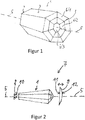
- a mixing rod 1 according to the invention is an elongated, monolithic body made of a transparent material ( Fig. 1 ).
- the mixing rod 1 has a light entry surface 2, a lateral surface 3 and a light exit surface 4.
- An optical axis 5 extends through the center of the light entry surface 2 and the center of the light exit surface 4.
- the light entry surface 2 is planar and perpendicular to the optical axis. 5
- the light exit surface 4 is substantially convexly curved and composed of several smooth facets 6.
- the light exit surface 4 of two annular sets of seven facets 6/1 and 6/2 and a central facet 6/3 is formed.
- the annularly arranged facets 6/1 and 6/2 are each planar facets, wherein the central facet 6/3 has a slight convex curvature.
- the mixing rod 1 has a polygonal cross section, wherein the cross section in the present embodiment is a heptagon (heptagon). Accordingly, the lateral surface 3 is formed of seven planar segments.
- the mixing rod 1 may also be formed with a different cross-sectional shape.
- the polygon preferably has an odd number of vertices.
- the polygons are preferably regular polygons.
- the light entry surface 2 is formed planar. In the context of the invention, it may be expedient that the light entry surface 2 is concave or convex.
- the cross-sectional area is smaller at the light entry surface 2 than at the light exit surface 4, so that the mixing rod widens conically from the light entry surface 2 to the light exit surface 4.
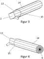
- the light source 8 is a light-emitting diode array with a plurality of light-emitting diodes 10.
- the light-emitting diode array 8 is arranged perpendicular to the optical axis 5 of the mixing rod 1 and with the light emitting diodes 10 pointing in the direction of the light entry surface 2. As a result, the light emitted by the light-emitting diodes 10 enters the mixing rod 1 at the light entry surface 2.
- the distance between the Light emitting diode array 8 and the light entrance surface 2 is as small as possible in order to capture as much as possible of the total amount of light with the mixing rod 1.
- FIG. 2 is the distance between the light-emitting diode array 8 and the light entry surface 2 larger than shown in reality for easier graphical representation.
- the lens 9 is arranged adjacent to the light exit surface 4 of the mixing rod 1.
- the lens 9 is arranged concentrically to the optical axis 5 of the mixing rod and is movable along the optical axis 5.
- suitable guide elements are provided, which are known in the art and for easier graphical representation in FIG. 2 are omitted.
- the lens 9 has a convexly curved surface 11 facing the mixing rod 1 and a convexly curved surface 12 facing away from the mixing rod 1.
- the surface facing the mixing rod 1 surface 11 is planar, concave or otherwise curved.
- the lens 9 is preferably also formed of a plastic material, in particular a plastic material based on silicone.
- the lens 9 can be moved very close to the light exit surface 4. The closer the lens 9 is to the light exit surface 4, the more the expansion of the cone of the light beam is changed by moving the lens. Therefore, it is expedient that there are no further optical elements in the region between the light exit surface 4 and the lens 9, so that the lens 9 can be moved to the light exit surface 4.
- the largest possible adjustable angle range is very advantageous.
- the light exit surface 4 has a dual function, on the one hand by the curvature causes a lens function of the mixing rod 1 and on the other hand promotes the mixing of the light beam by providing the plurality of facets 6.
- the mixing rod 1 preferably has at least four facets, in particular at least ten facets and particularly preferably at least fifteen facets.
- the number of facets at the exit should not be greater than 200 and in particular not greater than 150 or not greater than 100.
- the maximum number of facets may be limited by the manufacturing process. In injection molding, small facets can not be represented and result in a more or less uniformly curved surface, which reduces the mixing effect of the faceting.
- the mixing of the light beam is enhanced by the polygonal shape of the cross section of the mixing rod 1, in particular an odd number of corners of the mixing rod 1.
- both the lateral surface 3 of smooth segments and the light exit surface 4 are composed of smooth facets 6, the light losses on the mixing rod 1 are very small.
- a lighting device in which light of an inhomogeneous light source is mixed very well in a simple manner, the light losses are small and the expansion of the light beam over a large range by moving the lens 9 is adjustable.
- the lighting device may also have a plurality of mixing rods, wherein each mixing rod is associated with at least one light source.
- the individual mixing rods are preferably arranged parallel to one another.
- the individual mixing rods are preferably identical.
- Each mixing rod may be associated with a separate lens.
- the lenses are moved together or in groups along the optical axis of the individual mixing rods. However, it can also be provided a common lens, which covers the light exit surfaces of all mixing rods.
- a mixing rod 1 is an elongate, monolithic body of a transparent material ( 3 and 4 ).
- the mixing rod 1 has a light entry surface 2, a lateral surface 3 and a light exit surface 4.
- An optical axis 5 extends through the center of the light entry surface 2 and the center of the light exit surface 4.
- the light exit surface 4 is substantially convexly curved and composed of several smooth facets 6.
- the light exit surface 4 is formed from six annularly arranged sets of 24 facets 6 each.
- the annularly arranged facets 6 are each planar facets.
- the mixing rod 1 similar to an obelisk, in two sections, in a shape transfer section 13 and in a homogenization section 14, divided.
- the transition between the two sections is given by an interface 15.
- the shape transfer section 13 and the homogenization section 14 are arranged one behind the other along the optical axis.
- the shape transfer section 13 starts with the light entry surface 2 and ends at the interface 15, wherein the interface 15 is formed perpendicular to the optical axis 5.
- the shape transfer section 13 has essentially a constant diameter from the light entry surface 2 in the direction of the light exit surface 4. This changes the shape of the cross-sectional area.
- the light entrance surface 2 corresponds to a planar square and is perpendicular to the optical axis 5.
- the cross section of the mold transfer section 13 corresponds to an Elfeck.
- the shape transfer section 13 may also be formed with a different cross-sectional shape in both the light entry surface 2 and the interface 15.
- the lateral surface 3 of the shape transfer section 13 is formed of eleven planar segments, thereby leading the cross section of a quadrangle in an Elfeck over.
- the homogenization section 14 is arranged after the shape transfer section 13, begins with the interface 15 and ends with the light exit surface 4. In this embodiment, the homogenization section 14 occupies about 80% of the total length between the light entry surface 2 and the light exit surface 4 of the mixing rod 1. Over the entire length of the homogenization section 14, from the boundary surface 15 to the light exit surface 4, its cross-sectional area is constant.
- the shape of the cross section of the homogenization section 14 is constant over its entire length range and corresponds to the shape which forms the shape transfer section 13 at the interface 15. But it is also conceivable that the size of the surface of the cross section remains approximately constant and the shape changes.
- the lateral surface 3 of the homogenization section 14 is formed of eleven planar segments.
- the size of the cross section of the homogenization section 14 has an area of at least 5 mm 2 , preferably at least 10 mm 2 and in particular at least 20 mm 2 .
- the mixing rod may be part of a lighting device 7.
- it also has a light source 8 and a lens 9 ( FIGS. 5 and 6 ).
- Light source 8 and lens 9 are formed as in the previous embodiment.
- a lens is arranged adjacent to the light exit surface of the lens.
- This has in particular holographic, micro and / or nanostructures.
- Microstructures may be, for example, air bubbles embedded in quartz glass.
- the mixing rod may have a section widening in the direction of the exit surface between the homogenization section and the exit surface. With such a widening section, additional bundling of the light beam can take place
- the diameter of the cross-sectional area of the homogenizing section 14 is about 3.5 mm.
- the length of the homogenization section 14 is 40 mm.
- the length and width of the square light entrance surface 4 is 2.4 mm each.
- the different prototypes had shape transfer sections with different lengths of 2 mm, 3 mm, 5 mm and 10 mm.
- the mixing rod with a shape transfer section 13 of 10 mm length results in a light beam with high luminance and good homogenization. With a length of the shape transfer portion of 5 mm, the luminance is good, good at a length of 3 mm and bad at a length of 2 mm.
- the length of the homogenization section is freely selectable per se. The longer the homogenization section, the better the homogenization.
- the shape transfer section 13 can be dispensed with. Then, the homogenizing section 14 has a widening portion and a constant portion.
Landscapes
- Physics & Mathematics (AREA)
- General Physics & Mathematics (AREA)
- Optics & Photonics (AREA)
- Non-Portable Lighting Devices Or Systems Thereof (AREA)
- Securing Globes, Refractors, Reflectors Or The Like (AREA)
Applications Claiming Priority (1)
| Application Number | Priority Date | Filing Date | Title |
|---|---|---|---|
| DE102018106956.1A DE102018106956A1 (de) | 2018-03-23 | 2018-03-23 | Mischstab zum Mischen eines Lichtstrahlbündels sowie Beleuchtungsvorrichtung mit einem solchen Mischstab |
Publications (4)
| Publication Number | Publication Date |
|---|---|
| EP3543600A2 true EP3543600A2 (fr) | 2019-09-25 |
| EP3543600A3 EP3543600A3 (fr) | 2019-10-16 |
| EP3543600C0 EP3543600C0 (fr) | 2025-11-05 |
| EP3543600B1 EP3543600B1 (fr) | 2025-11-05 |
Family
ID=65904162
Family Applications (1)
| Application Number | Title | Priority Date | Filing Date |
|---|---|---|---|
| EP19164262.8A Active EP3543600B1 (fr) | 2018-03-23 | 2019-03-21 | Tige de mélange permettant de mélanger un faisceau de rayons lumineux ainsi que dispositif d'éclairage doté d'une telle tige de mélange |
Country Status (2)
| Country | Link |
|---|---|
| EP (1) | EP3543600B1 (fr) |
| DE (1) | DE102018106956A1 (fr) |
Cited By (1)
| Publication number | Priority date | Publication date | Assignee | Title |
|---|---|---|---|---|
| CN111928133A (zh) * | 2020-04-03 | 2020-11-13 | 苏州欧普照明有限公司 | 一种配光透镜、照明灯具及照明模组 |
Families Citing this family (1)
| Publication number | Priority date | Publication date | Assignee | Title |
|---|---|---|---|---|
| EP4715257A1 (fr) * | 2024-06-19 | 2026-03-25 | DMV d.o.o. | Elément optique |
Family Cites Families (20)
| Publication number | Priority date | Publication date | Assignee | Title |
|---|---|---|---|---|
| US4656562A (en) * | 1985-09-13 | 1987-04-07 | Santa Barbara Research Center | Optical integrator means for intensity modification of Gaussian beam |
| JP2005517968A (ja) * | 2001-06-11 | 2005-06-16 | ハネウェル・インターナショナル・インコーポレーテッド | 光分配構成部品 |
| JP4274766B2 (ja) * | 2002-09-12 | 2009-06-10 | オリンパス株式会社 | 照明装置及びその照明装置を使用した画像投影装置 |
| GB2395289A (en) | 2002-11-11 | 2004-05-19 | Qinetiq Ltd | Structured light generator |
| US20050007346A1 (en) * | 2003-07-11 | 2005-01-13 | Guolin Ma | Optical conduit for channeling light onto a surface |
| JP2005070443A (ja) * | 2003-08-25 | 2005-03-17 | Olympus Corp | 光学装置、照明装置及びプロジェクタ |
| DE102006004996A1 (de) * | 2005-02-01 | 2006-08-24 | Schott Ag | Lichtmischer für LED |
| DE102005018336A1 (de) * | 2005-02-28 | 2006-08-31 | Osram Opto Semiconductors Gmbh | Lichtleiter |
| FR2888917B1 (fr) * | 2005-07-21 | 2009-11-20 | Valeo Vision | Dispositif d'eclairage ou de signalisation, notamment pour vehicule automobile |
| US7777955B2 (en) | 2005-07-29 | 2010-08-17 | Optical Research Associates | Rippled mixers for uniformity and color mixing |
| FR2916832B1 (fr) * | 2007-06-04 | 2013-08-02 | Valeo Vision | Dispositif de couplage optique entre au moins une source et une guide de lumiere, et dispositif de signalisation et/ou d'eclairage pour vehicule automobile |
| US20110199558A1 (en) * | 2009-01-22 | 2011-08-18 | Sharp Kabushiki Kaisha | Backlight unit and liquid crystal display device |
| WO2012014141A1 (fr) * | 2010-07-30 | 2012-02-02 | Kla-Tencor Corporation | Illuminateur de lumière annulaire, organe de mise en forme de faisceau, et procédé d'éclairage |
| EP2656123B1 (fr) | 2010-12-23 | 2022-05-11 | Harman Professional Denmark ApS | Mélangeur de lumière optique projetant un faisceau de lumière uniforme et homogénéisé |
| EP2810113A1 (fr) | 2012-02-01 | 2014-12-10 | Koninklijke Philips N.V. | Procédé, système optique, et dispositif d'éclairage pour homogénéiser la lumière |
| DE102012111313B4 (de) * | 2012-11-23 | 2023-09-28 | HELLA GmbH & Co. KGaA | Beleuchtungseinheit für ein Kraftfahrzeug |
| WO2015051031A2 (fr) * | 2013-10-01 | 2015-04-09 | Robe Lighting, Inc. | Système de mise au point et d'homogénéisation pour luminaire à del |
| EP3161375A1 (fr) * | 2014-06-27 | 2017-05-03 | Philips Lighting Holding B.V. | Lentille, dispositif d'éclairage et luminaire |
| DE102015011714A1 (de) * | 2015-09-07 | 2017-03-09 | Bartenbach Holding Gmbh | Beleuchtungsvorrichtung |
| US9810904B1 (en) * | 2016-11-11 | 2017-11-07 | Google Inc. | Fresnel lens assembly having varying facet angle |
-
2018
- 2018-03-23 DE DE102018106956.1A patent/DE102018106956A1/de not_active Withdrawn
-
2019
- 2019-03-21 EP EP19164262.8A patent/EP3543600B1/fr active Active
Cited By (1)
| Publication number | Priority date | Publication date | Assignee | Title |
|---|---|---|---|---|
| CN111928133A (zh) * | 2020-04-03 | 2020-11-13 | 苏州欧普照明有限公司 | 一种配光透镜、照明灯具及照明模组 |
Also Published As
| Publication number | Publication date |
|---|---|
| EP3543600A3 (fr) | 2019-10-16 |
| EP3543600C0 (fr) | 2025-11-05 |
| DE102018106956A1 (de) | 2019-09-26 |
| EP3543600B1 (fr) | 2025-11-05 |
Similar Documents
| Publication | Publication Date | Title |
|---|---|---|
| EP2893249B1 (fr) | Unité d'éclairage destinée à un projecteur | |
| EP3329179B1 (fr) | Dispositif d'illumination pour un phare de véhicule | |
| EP3084496B1 (fr) | Élément optique et système d'émission de lumière | |
| DE102008036845B4 (de) | Beleuchtungsvorrichtung | |
| DE102008048751A1 (de) | Leuchte für Kraftfahrzeuge | |
| DE69518603T2 (de) | Fahrzeugscheinwerfer | |
| EP2618045A1 (fr) | Dispositif dýéclairage pour un véhicule automobile | |
| WO2017186465A1 (fr) | Optique d'éclairage | |
| DE102006037797B4 (de) | Kraftfahrzeugleuchte | |
| EP3130843A1 (fr) | Dispositif de mélange et de conduction d'un rayonnement électromagnétique | |
| DE112013005281T5 (de) | Optisches Element mit einem TIR-Flächenabschnitt für verbesserte räumliche Lichtverteilung | |
| EP3543600B1 (fr) | Tige de mélange permettant de mélanger un faisceau de rayons lumineux ainsi que dispositif d'éclairage doté d'une telle tige de mélange | |
| DE19930461A1 (de) | Fahrzeugleuchte | |
| EP3623695A1 (fr) | Luminaire ainsi que procédé de commande des caractéristiques du rayonnement dudit luminaire, conduit de mélangeur de lumière et luminaire pourvu de conduit de mélangeur de lumière | |
| DE202017103122U1 (de) | Zoom-Strahler | |
| EP1512902A2 (fr) | Lampe pour agencement sur la surface d'un batiment | |
| DE102018207516B3 (de) | Head-Up-Display mit einer von mehreren verteilt angeordneten Lichtquellen beleuchteten Anzeige | |
| DE102007038205B4 (de) | Leuchte mit Lichtleiterplatte | |
| DE102015210372B4 (de) | Signallichtmodul für ein Kraftfahrzeug | |
| EP1156268B1 (fr) | Lampe à guide de lumière avec structure réfractive non uniforme | |
| EP3623694A1 (fr) | Luminaire ainsi que procédé de commande des caractéristiques du rayonnement dudit luminaire, conduit de mélangeur de lumière et luminaire pourvu de conduit de mélangeur de lumière | |
| DE102020117789A1 (de) | Leuchte | |
| DE102019126521A1 (de) | Beleuchtungskörper | |
| DE102014220105B4 (de) | Lichtleiter und Kfz-Beleuchtungseinrichtung | |
| EP4715257A1 (fr) | Elément optique |
Legal Events
| Date | Code | Title | Description |
|---|---|---|---|
| PUAI | Public reference made under article 153(3) epc to a published international application that has entered the european phase |
Free format text: ORIGINAL CODE: 0009012 |
|
| STAA | Information on the status of an ep patent application or granted ep patent |
Free format text: STATUS: THE APPLICATION HAS BEEN PUBLISHED |
|
| PUAL | Search report despatched |
Free format text: ORIGINAL CODE: 0009013 |
|
| AK | Designated contracting states |
Kind code of ref document: A2 Designated state(s): AL AT BE BG CH CY CZ DE DK EE ES FI FR GB GR HR HU IE IS IT LI LT LU LV MC MK MT NL NO PL PT RO RS SE SI SK SM TR |
|
| AX | Request for extension of the european patent |
Extension state: BA ME |
|
| AK | Designated contracting states |
Kind code of ref document: A3 Designated state(s): AL AT BE BG CH CY CZ DE DK EE ES FI FR GB GR HR HU IE IS IT LI LT LU LV MC MK MT NL NO PL PT RO RS SE SI SK SM TR |
|
| AX | Request for extension of the european patent |
Extension state: BA ME |
|
| RIC1 | Information provided on ipc code assigned before grant |
Ipc: G02B 27/09 20060101ALI20190910BHEP Ipc: F21V 8/00 20060101AFI20190910BHEP |
|
| STAA | Information on the status of an ep patent application or granted ep patent |
Free format text: STATUS: REQUEST FOR EXAMINATION WAS MADE |
|
| 17P | Request for examination filed |
Effective date: 20200415 |
|
| RBV | Designated contracting states (corrected) |
Designated state(s): AL AT BE BG CH CY CZ DE DK EE ES FI FR GB GR HR HU IE IS IT LI LT LU LV MC MK MT NL NO PL PT RO RS SE SI SK SM TR |
|
| STAA | Information on the status of an ep patent application or granted ep patent |
Free format text: STATUS: EXAMINATION IS IN PROGRESS |
|
| 17Q | First examination report despatched |
Effective date: 20210628 |
|
| GRAP | Despatch of communication of intention to grant a patent |
Free format text: ORIGINAL CODE: EPIDOSNIGR1 |
|
| STAA | Information on the status of an ep patent application or granted ep patent |
Free format text: STATUS: GRANT OF PATENT IS INTENDED |
|
| RIC1 | Information provided on ipc code assigned before grant |
Ipc: G02B 27/09 20060101ALN20250430BHEP Ipc: G02B 19/00 20060101ALI20250430BHEP Ipc: F21V 8/00 20060101AFI20250430BHEP |
|
| INTG | Intention to grant announced |
Effective date: 20250526 |
|
| GRAS | Grant fee paid |
Free format text: ORIGINAL CODE: EPIDOSNIGR3 |
|
| GRAA | (expected) grant |
Free format text: ORIGINAL CODE: 0009210 |
|
| STAA | Information on the status of an ep patent application or granted ep patent |
Free format text: STATUS: THE PATENT HAS BEEN GRANTED |
|
| AK | Designated contracting states |
Kind code of ref document: B1 Designated state(s): AL AT BE BG CH CY CZ DE DK EE ES FI FR GB GR HR HU IE IS IT LI LT LU LV MC MK MT NL NO PL PT RO RS SE SI SK SM TR |
|
| REG | Reference to a national code |
Ref country code: CH Ref legal event code: F10 Free format text: ST27 STATUS EVENT CODE: U-0-0-F10-F00 (AS PROVIDED BY THE NATIONAL OFFICE) Effective date: 20251105 Ref country code: GB Ref legal event code: FG4D Free format text: NOT ENGLISH |
|
| RIN1 | Information on inventor provided before grant (corrected) |
Inventor name: HOFFMANN, HELGE Inventor name: TOBUSCHAT, HANS ULRICH |
|
| REG | Reference to a national code |
Ref country code: DE Ref legal event code: R096 Ref document number: 502019014051 Country of ref document: DE |
|
| REG | Reference to a national code |
Ref country code: IE Ref legal event code: FG4D Free format text: LANGUAGE OF EP DOCUMENT: GERMAN |
|
| U01 | Request for unitary effect filed |
Effective date: 20251203 |
|
| U07 | Unitary effect registered |
Designated state(s): AT BE BG DE DK EE FI FR IT LT LU LV MT NL PT RO SE SI Effective date: 20251211 |
|
| PGFP | Annual fee paid to national office [announced via postgrant information from national office to epo] |
Ref country code: GB Payment date: 20260312 Year of fee payment: 8 |
|
| PG25 | Lapsed in a contracting state [announced via postgrant information from national office to epo] |
Ref country code: ES Free format text: LAPSE BECAUSE OF FAILURE TO SUBMIT A TRANSLATION OF THE DESCRIPTION OR TO PAY THE FEE WITHIN THE PRESCRIBED TIME-LIMIT Effective date: 20251105 |
|
| PG25 | Lapsed in a contracting state [announced via postgrant information from national office to epo] |
Ref country code: NO Free format text: LAPSE BECAUSE OF FAILURE TO SUBMIT A TRANSLATION OF THE DESCRIPTION OR TO PAY THE FEE WITHIN THE PRESCRIBED TIME-LIMIT Effective date: 20260205 |
|
| PG25 | Lapsed in a contracting state [announced via postgrant information from national office to epo] |
Ref country code: HR Free format text: LAPSE BECAUSE OF FAILURE TO SUBMIT A TRANSLATION OF THE DESCRIPTION OR TO PAY THE FEE WITHIN THE PRESCRIBED TIME-LIMIT Effective date: 20251105 |
|
| U20 | Renewal fee for the european patent with unitary effect paid |
Year of fee payment: 8 Effective date: 20260310 |
|
| PG25 | Lapsed in a contracting state [announced via postgrant information from national office to epo] |
Ref country code: RS Free format text: LAPSE BECAUSE OF FAILURE TO SUBMIT A TRANSLATION OF THE DESCRIPTION OR TO PAY THE FEE WITHIN THE PRESCRIBED TIME-LIMIT Effective date: 20260205 |
|
| PG25 | Lapsed in a contracting state [announced via postgrant information from national office to epo] |
Ref country code: IS Free format text: LAPSE BECAUSE OF FAILURE TO SUBMIT A TRANSLATION OF THE DESCRIPTION OR TO PAY THE FEE WITHIN THE PRESCRIBED TIME-LIMIT Effective date: 20260305 |
|
| PGFP | Annual fee paid to national office [announced via postgrant information from national office to epo] |
Ref country code: CZ Payment date: 20260310 Year of fee payment: 8 |
|
| PG25 | Lapsed in a contracting state [announced via postgrant information from national office to epo] |
Ref country code: PL Free format text: LAPSE BECAUSE OF FAILURE TO SUBMIT A TRANSLATION OF THE DESCRIPTION OR TO PAY THE FEE WITHIN THE PRESCRIBED TIME-LIMIT Effective date: 20251105 |
|
| PG25 | Lapsed in a contracting state [announced via postgrant information from national office to epo] |
Ref country code: SM Free format text: LAPSE BECAUSE OF FAILURE TO SUBMIT A TRANSLATION OF THE DESCRIPTION OR TO PAY THE FEE WITHIN THE PRESCRIBED TIME-LIMIT Effective date: 20251105 |
|
| PG25 | Lapsed in a contracting state [announced via postgrant information from national office to epo] |
Ref country code: SK Free format text: LAPSE BECAUSE OF FAILURE TO SUBMIT A TRANSLATION OF THE DESCRIPTION OR TO PAY THE FEE WITHIN THE PRESCRIBED TIME-LIMIT Effective date: 20251105 |