EP3543607A1 - Blaurauch-brenner für die rauchgasentgiftung einer asphaltmischanlage, entsprechende asphaltmischanlage und entsprechendes entgiftungsverfahren - Google Patents
Blaurauch-brenner für die rauchgasentgiftung einer asphaltmischanlage, entsprechende asphaltmischanlage und entsprechendes entgiftungsverfahren Download PDFInfo
- Publication number
- EP3543607A1 EP3543607A1 EP19163903.8A EP19163903A EP3543607A1 EP 3543607 A1 EP3543607 A1 EP 3543607A1 EP 19163903 A EP19163903 A EP 19163903A EP 3543607 A1 EP3543607 A1 EP 3543607A1
- Authority
- EP
- European Patent Office
- Prior art keywords
- burner
- flow
- bitumen
- conduit
- supply line
- Prior art date
- Legal status (The legal status is an assumption and is not a legal conclusion. Google has not performed a legal analysis and makes no representation as to the accuracy of the status listed.)
- Granted
Links
Images

Classifications
-
- F—MECHANICAL ENGINEERING; LIGHTING; HEATING; WEAPONS; BLASTING
- F23—COMBUSTION APPARATUS; COMBUSTION PROCESSES
- F23G—CREMATION FURNACES; CONSUMING WASTE PRODUCTS BY COMBUSTION
- F23G7/00—Incinerators or other apparatus for consuming industrial waste, e.g. chemicals
- F23G7/06—Incinerators or other apparatus for consuming industrial waste, e.g. chemicals of waste gases or noxious gases, e.g. exhaust gases
- F23G7/061—Incinerators or other apparatus for consuming industrial waste, e.g. chemicals of waste gases or noxious gases, e.g. exhaust gases with supplementary heating
- F23G7/065—Incinerators or other apparatus for consuming industrial waste, e.g. chemicals of waste gases or noxious gases, e.g. exhaust gases with supplementary heating using gaseous or liquid fuel
-
- E—FIXED CONSTRUCTIONS
- E01—CONSTRUCTION OF ROADS, RAILWAYS, OR BRIDGES
- E01C—CONSTRUCTION OF, OR SURFACES FOR, ROADS, SPORTS GROUNDS, OR THE LIKE; MACHINES OR AUXILIARY TOOLS FOR CONSTRUCTION OR REPAIR
- E01C19/00—Machines, tools or auxiliary devices for preparing or distributing paving materials, for working the placed materials, or for forming, consolidating, or finishing the paving
- E01C19/02—Machines, tools or auxiliary devices for preparing or distributing paving materials, for working the placed materials, or for forming, consolidating, or finishing the paving for preparing the materials
- E01C19/10—Apparatus or plants for premixing or precoating aggregate or fillers with non-hydraulic binders, e.g. with bitumen, with resins, i.e. producing mixtures or coating aggregates otherwise than by penetrating or surface dressing; Apparatus for premixing non-hydraulic mixtures prior to placing or for reconditioning salvaged non-hydraulic compositions
-
- F—MECHANICAL ENGINEERING; LIGHTING; HEATING; WEAPONS; BLASTING
- F23—COMBUSTION APPARATUS; COMBUSTION PROCESSES
- F23G—CREMATION FURNACES; CONSUMING WASTE PRODUCTS BY COMBUSTION
- F23G2209/00—Specific waste
- F23G2209/14—Gaseous waste or fumes
Definitions
- the present invention relates to the general technical field of equipment and coating processes, for example for the manufacture of bituminous coated products from bitumen and aggregates, in particular gravel of various types, of different grain size and size, with a view to to produce a finished coated product that can be used for example in the field of construction and public works.
- the present invention relates more particularly to a burner for equipping a furnace with a coating plant for manufacturing hot bituminous mixes from aggregates and bitumen, said burner comprising at least one burning head and a pipe of supply of oxidant to the burning head to produce at the latter a flame for heating the interior of said furnace.
- the present invention also relates to a coating plant for the manufacture of hot bituminous mix from aggregates and bitumen, said plant comprising an oven and a burner.
- the present invention furthermore relates to a process for the depollution of a coating plant intended to manufacture hot bituminous mixes from aggregates and bitumen, said plant comprising an oven, said method comprising at least one step of equipping said coating plant. oven with a burner comprising at least one burning head and an oxidizer supply line to the burning head to produce at the latter a flame for heating the interior of said furnace.
- Coating plants are known for making bituminous mixes, that is to say in practice to make a hot mix of gravel and / or sand type solid products with at least one substantially molten, soft binder, and or hot liquid, such as bitumen.
- a hot mix of gravel and / or sand type solid products with at least one substantially molten, soft binder, and or hot liquid, such as bitumen.
- Such a mixture is particularly used in the field of construction, in particular for making communication routes (for example a pavement of a road, a sidewalk, an airport runway, etc.), public works (courses school, parking, etc.), buildings or civil engineering (eg as a coating or sealant), etc.
- Such plants generally each comprise an oven for drying gravel to remove all traces of water, the dried gravel is then mixed with hot bitumen to form bituminous mixes.
- Bituminous mixes are then stored in the plant and loaded into a truck for evacuation.
- the objects assigned to the invention therefore aim to remedy the various disadvantages mentioned above and to propose a new burner for a coating plant enabling it to manufacture asphalt mixtures in a particularly clean, environmentally friendly and safe manner. health, while allowing good reliability and high production efficiency.
- Another object assigned to the invention is to propose a new burner for coating plant, allowing, whatever the production capacity of the plant, to minimize the discharge of bituminous pollutants.
- Another object of the invention is to provide a new burner easy and inexpensive to install on a asphalt plant under construction or a pre-existing plant.
- Another object assigned to the invention is to propose a new coating plant of relatively simple construction and inexpensive.
- Another object assigned to the invention is to propose a new coating plant whose design makes it possible to optimally limit pollutant emissions into the atmosphere.
- Another object assigned to the invention is to propose a new coating plant whose design makes it easier to maintain.
- Another object assigned to the invention is to propose a new process of depollution of a coating plant to limit continuously pollutant emissions based on bitumen in the atmosphere, and whatever the mode of the plant or burner and without significantly impacting the performance of the latter.
- the objects assigned to the invention are also achieved by means of a coating plant for the manufacture of hot bituminous mix from aggregates and bitumen, said plant comprising an oven and being characterized in that it further comprises at least one burner as mentioned above.
- the invention relates, according to a first aspect, as illustrated in the figures, a burner 32 for equipping a furnace 2 with a coating plant 1 for manufacturing hot bituminous mixes from aggregates and bitumen.
- the coating plant 1 comprises in particular a furnace 2, which is preferably designed to dry aggregates, that is to say designed to heat treatment said aggregates in order to eliminate the water that would be incorporated into these.
- the oven 2 is therefore advantageously an aggregate drying oven, but may optionally form a bituminous mix production unit in the case where the hot bitumen / aggregates mixture is carried out at least partly inside the oven 2.
- the burner 32 is therefore advantageously intended to equip the coating plant 1, and more preferably the furnace 2 of said central 1, or even to form a part of the central 1, to provide two main functions.
- the first function devolving on the burner 32 is to provide, in a conventional manner, the heating of the furnace 2 which it is intended to equip, that is to say an increase in the temperature inside said furnace 2, and this in particular for drying aggregates.
- a second function of the burner 32 is more specific to the invention, and advantageously relates to the depollution of the coating plant 1, the burner 32 being intended to destroy, in particular by burning, in an effective and controlled manner, the vapors and / or bitumen dust from the bitumen used by the plant 1 and / or bituminous mixes manufactured by the latter, and preferably inside the furnace 2 of the coating plant 1.
- the burner 32 has, in addition to its traditional function of heating the oven 2, a depollution function of the coating plant 1, the burner 32 being intended to be mounted, that is to say set placed or installed, in combination with the furnace 2 of the coating plant 1 to perform both its heating function and its depollution function.
- the coating plant 1 preferably constitutes a hot bituminous mix production unit, that is to say in particular a mixture of preferably solid aggregates, and a binder, advantageously a hydrocarbon-type binder.
- bitumen preferably soft, liquid, viscous and / or hot melted.
- the bituminous mixes manufactured by the Central 1 are intended to be used in public works, civil engineering, building, or more generally all that relates to the construction, in particular the construction of roads, of airport runways but also for other applications, for example as a sealant or insulation.
- the coating plant 1 is therefore in particular intended to store and use bitumen, and in particular hot bitumen, and mix it with aggregates to manufacture hot bituminous mixes, for example at a temperature of between 100 and 250 ° C. C, preferably between 120 and 180 ° C.
- the aggregates are formed by solid granular products, and are included in the group comprising gravel, crushed pebbles, fines (or " filler ") and sand.
- the granules preferably have a small particle size, for example they have a mean size (or an average diameter) substantially less than or equal to 125 mm, or even less than or equal to 20 mm.
- bitumen refers to any bitumen binder used for the manufacture of asphalt, whether natural bitumen (for example from deposits), plant (for example derived from plants), synthetic or artificial (eg from crude oil and / or petrochemicals).
- the bitumen used in the coating plant 1 is mainly (that is to say at least a majority) formed by a mixture of petroleum hydrocarbons.
- the coating plant 1 in particular produces, undesirably, vapors and / or dust bitumen, which are derived from the bitumen used by the plant 1 and / or asphalt produced by the latter.
- These vapors and / or bitumen dust are commonly referred to as " blue fumes" in the field, and constitute highly polluting by-products or waste residues. particularly resulting from the implementation of the coating plant 1.
- blue fumes are also derived from the storage and disposal of bituminous mixes in the plant 1. Blue fumes are also formed during the storage of bitumen for use by the plant 1 for manufacturing bituminous mixes, that is to say the bitumen intended to be mixed with the aggregates.
- the burner 32 comprises at least one burning head 3 and an oxidant feed pipe 38 to the burning head 3 to produce at the latter a flame 4 for heating the inside of said furnace 2
- the oxidant supply line 38 is advantageously designed to convey, at least up to the burning head 3 (also called the combustion head 3), an oxidant, which is preferably air and more preferably the oxygen contained in the air, to allow the production of the flame 4, that is to say in particular the realization of a combustion of which one of the reactants is said oxidant.
- the burner 32 is therefore designed to produce the flame 4 from a position or zone defining the burning head 3, and this by means of the oxidizer supply line 38, the flame 4 ensuring advantageously, the main function of heating the oven 2 (and more advantageously still a drying function of the aggregates).
- the oxidizer supply line 38 is designed to supply the burner 32 with fuel.
- the oxidizer feed line 38 may for example be formed of a single pipe, or a plurality of pipes preferably fluidly connected to each other.
- the burner 32 further comprises at least one fuel supply line 39, 46 to the burning head 3 to produce at the latter flame 4, that is to say to achieve combustion, and that of preferably in combination with the oxidizer supply line 38 or more precisely the oxidant conveyed by the latter.
- the fuel supply pipe 39, 46 is advantageously designed to convey, at least up to the burning head 3, a fuel, which is in particular liquid or gaseous, such as for example natural or synthetic gas, fuel, oil, or any other suitable fuel for the production of the flame 4 necessary for heating the oven 2 (preferably drying, optionally mixing) of a coating plant 1.
- a fuel which is in particular liquid or gaseous, such as for example natural or synthetic gas, fuel, oil, or any other suitable fuel for the production of the flame 4 necessary for heating the oven 2 (preferably drying, optionally mixing) of a coating plant 1.
- the burner 32 comprises a first fuel supply pipe 39 for conveying liquid fuel, and a second fuel supply pipe 46 for conveying gaseous fuel, said liquid fuel 39 and gas supply lines 46. being advantageously distinct and intended to be used alternately, that is to say non-concomitantly.
- the second fuel supply conduit 46 comprises for example a major conduit and a plurality of minor conduits 46a, 46b forming a corolla, said minor conduits 46a, 46b being fluidly connected to the major conduit to extend from the latter to the burning head 3, the major duct being located upstream of the minor ducts 46a, 46b.
- the burner 32 comprises only the first fuel supply pipe 39 or the second fuel supply pipe 46, the burner 32 then being intended to produce the flame 4 only with a liquid fuel or with a gaseous fuel, without alternation.
- the burner 32 may for example form a forced-air gas burner or an oil-fired burner, depending on the nature of the fuel (fuel gas or fuel).
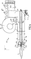
- the burning head 3 is thus preferably formed, conventionally, by the position or zone where the production of the flame 4 begins, and it can also advantageously comprise, just as conventionally, as illustrated in FIG. figure 4 , a fuel injection means disposed at the end of the fuel supply pipe 39, 46 (or forming an end thereof).
- the fuel injection means therefore preferably forms both a part, preferably an extremal part, of the fuel supply pipe 39, 46, and at least a part of the burning head 3.
- the fuel injection means comprises a primary liquid fuel injection head 45 disposed at the end of the first fuel supply pipe 39, and a plurality of secondary fuel gas injection heads 47a, 47b disposed at respective ends of respective minor ducts 46a, 46b, particularly at the ends of the corolla.
- the burning head 3 is preferably located downstream of the oxidizer supply line 38 (that is to say at the downstream end thereof or at a downstream portion thereof). ).
- the flame 4 extends at least partially, preferably completely, within (that is to say inside) the furnace 2.
- the burning head 3 and the driving of supply of oxidant 38 are arranged so as to produce said flame 4 from the burning head 3, in the furnace 2, said flame 4 being formed, with respect to the burning head 3, opposite the pipe of FIG. supply of oxidant 38.
- the flame 4 advantageously extends from the burning head 3, opposite and / or outside the oxidizer supply line 38.
- the burner 32 is therefore advantageously intended for equipping said furnace 2 to raise the temperature inside the latter, the drying of the aggregates arranged inside the furnace is thus preferably carried out by means of the heat provided by said flame 4, which extends towards inside the oven 2 from the burning head, which is also positioned preferentially inside the furnace 2.
- Said burning head 3 and / or said oxidizer supply line 38 is / are therefore advantageously intended to be at least partially installed and / or mounted on and / or in said furnace 2.
- the burner 32 by means of the flame 4, is intended to heat the inside of the oven 2 to dry the aggregates.
- the burner 32 is possibly formed in part by a burner already installed in the coating plant 1, for example a pre-installed burner equipping the furnace 2 with a pre-existing coating plant 1, this pre-installed burner including for example the head
- the burner 32 is a new burner which forms a module designed to equip a coating plant 1 and in particular the furnace 2 of the latter.
- the oxidizer feed pipe 38 has a shape (at least partially or even entirely) tubular inside which the oxidant for supplying the flame 4 circulates.
- the fuel supply duct 39, 46 is positioned inside the oxidizer supply duct 38 and more precisely inside the tubular form, so that the oxidant circulates in the duct. supply of oxidant 38 and around the fuel supply pipe 39, 46, to produce the flame 4 when it is mixed with a fuel flowing in the fuel supply pipe 39, 46.
- the driving of fuel supply 39, 46 also has a tubular shape, but whose diameter is smaller than that of the tubular form of the oxidizer supply line 38.
- the oxidant feed and fuel supply lines 39, 46 are substantially elongated and positioned substantially coaxially, or along respective substantially parallel axes.
- the fuel supply line 39, 45 is positioned substantially coaxially with the oxidant supply line 38, such as for example the first fuel supply line 39, or along a longitudinal axis substantially parallel to an axis. longitudinal direction of the oxidizer supply line 38, such as for example the second fuel supply line 46.
- the burner 32 further comprises an ignition means 40 designed to allow the production of the flame 4, in particular by initiating a combustion reaction between the oxidizer conveyed by the oxidizer supply pipe 38 and the fuel supplied by the the fuel supply line 39, 46.
- Said ignition means 40 is therefore preferably designed to produce a source of ignition, such as a spark, an electric arc, a hot spot or an ignition flame (for example produced from LPG) at the burning head 3 (and / or in the immediate vicinity of the latter).
- the burning head 3 is formed by the zone or position where the flame 4 begins to exist, that is to say the zone where the oxidant is conveyed by the oxidizer feed pipe 38, the fuel conveyed by the fuel supply pipe 39, 46, and the ignition source produced by the ignition means 40.
- the oxidant supply pipe 38 has at one of its ends a primary outlet mouth 42 opening inside said oven 2 and located therein.
- the burning head 3 is located substantially at (or in the immediate vicinity) of the primary outlet mouth 42, the fuel injection means, and the ignition means 40.
- the flame 4 is therefore advantageously produced. substantially at a level, that is to say from, an area adjacent to the primary outlet mouth 42, the fuel injection means, and the ignition means 40.
- the burner 32 further comprises, preferably, a flame deflector 41 designed to regulate the flame 4, for example keep it in position.
- the deflector 41 is advantageously positioned at the level of the burning head 3 (or it forms part of it) inside the oxidizer supply line 38. This deflector 41 makes it possible, in particular, to pass a flow of oxidant (from the oxidizer feed line 38) to generate the turbulence necessary to maintain the flame 4 in position.
- the flame deflector 41 has a generally circular general shape and / or a complex shape of the type having a plurality of vents.
- the burner 32 is preferably designed to produce the flame 4 inside the drying oven 2 from an oxidant coming from the oxidizer feed pipe 38, a fuel coming from the fuel pipe.
- the fuel used by the burner 32 is formed by a liquid fuel (for example derived from crude oil) or a gaseous fuel (for example natural or synthetic gas), the oxidizer used by the burner 32 being for example formed by air, and more preferably by the oxygen contained in the air.
- the furnace 2 comprises, in known manner, a housing 5 and optionally forms a drum, at least a portion of which can be rotated, in particular for better drying the aggregates when said flame 4 is produced by the burner 32, preferably inside the housing 5.
- the aggregates are introduced into the drying oven 2 and removed from the latter by means of a conveyor (not shown).
- the oven 2 is designed so that the mixture of aggregates and bitumen is made inside the housing 5, the rotation of the drum that advantageously forms the oven 2 for example to achieve and / or homogenize the mixture.
- the oxidant feed pipe 38 advantageously has an end or part opening inside the furnace 2 and another end or part opening out from the furnace 2 (preferably in the first conduit 20), for example one end or part positioned inside the furnace 2 (and more precisely the housing 5), and another end or part positioned outside the latter.
- the oxidizer supply line 38 is therefore preferably designed for the production, for example at its first end, of a flame 4 inside the housing 5 of the oven 2, in order to ensure the production of heat within the furnace. oven 2 for drying aggregates.
- the coating plant 1 and / or the burner 32 further comprises at least one means 6 for collecting vapors and / or bitumen dust from the bitumen used by the plant 1 and / or bituminous mixes produced by the latter.
- the collecting means 6 may be part of the coating plant 1 and / or the burner 32, according to for example that the collection means 6 is already preinstalled in a pre-existing coating plant (where the the burner 32 of the invention), subsequently integrated in the latter (particularly at the same time as the installation of the burner 32), or installed in a new coating plant during its construction (in particularly at the same time as the burner 32).
- the coating plant 1 advantageously comprises at least one bitumen storage means 7, for example formed by a tank, and a bituminous mix storage means 8, for example formed by a storage hopper , an evacuation zone 9 for bituminous mixes, and a loading system 10 for loading a vehicle 11, for example a truck, with asphalt, in said discharge zone 9.
- the central unit 1 also comprises a means for producing bituminous mixes, said manufacturing means being able to be formed, as we have seen, at least in part by the oven 2, in particular if the latter forms a rotating drum.
- bituminous mix production means is preferably designed to mix bitumen (and in particular the bitumen stored in the plant 1 by said bitumen storage means 7) and aggregates (which are for example stored previously in the central 1 in an aggregates storage unit, not shown).
- bitumen dust is for example formed by small particles detached aggregates, especially during drying and / or the manufacture of asphalt, and which have been covered at least in part by a certain amount of bitumen including hot.
- Bitumen dusts are optionally also at least partly formed by small particles of bitumen which are at least partially solidified.
- the bitumen dust preferably has a very small particle size, for example they have an average size (or an average diameter) less than or equal to 0.2 mm, or even less than or equal to 20 microns.
- bitumen vapors are formed by volatile organic compounds (VOCs) and / or by aerosols of hydrocarbon molecules, said volatile organic compounds and / or aerosols being in particular derived from bitumen and especially hot bitumen.
- VOCs volatile organic compounds
- aerosols of hydrocarbon molecules
- the coating plant 1 comprises one or more collection points, which are for example designed to allow the evacuation of vapors and / or dust bitumen from the coating plant 1 out of the bitumen storage means 7, the means for manufacturing bituminous mixes, the means for storing mixes bituminous 8, and / or the evacuation zone 9 bituminous mixes, said collection points being formed for example by orifices or zones.
- the collection means 6 comprises at least one (and more preferably several) collection line (s), the one (s) of which is / are connected (each) to a respective collection point of the central 1, the said point (s) collection (s) being positioned respectively in the bitumen storage means 7, the bituminous mix production means, the bituminous mix storage means 8 and / or the evacuation zone 9 of bituminous mixes.
- the collecting means 6 comprises at least one or more primary, secondary, tertiary, and / or quaternary primary collection ducts 15, the one (s) of which is / are connected ( s) respectively by means of bitumen storage 7, by means of bituminous mix production (not illustrated), by means of storage of bituminous mixes 8, and / or the discharge zone 9 of bituminous mixes.
- the collection means 6 further comprises at least one single main collecting duct 16 in which several of the collection ducts 12, 13, 14, 15, or even all the ducts (that is to say, meet fluidly) meet fluidly. 12, 13, 14, 15.
- the collection means 6 comprises at least primary primary collecting ducts 17 and secondary 18 gathering (that is to say putting into fluid communication) each one or more collection ducts 12, 13, 14, 15, the main primary collection duct 17 gathering for example said secondary collection ducts 13 and tertiary 14, while the main secondary collection duct 18 for example collects said primary collection ducts 12 and quaternary 15.
- said primary primary collection ducts 17 and secondary 18 themselves collect (i.e., join fluidically), downstream, at a branch 19 (which is advantageously part of the collection means 6) .
- the number and configuration of the collection ducts 12, 13, 14, 15, 16, 17 are not necessarily fixed, and may vary from one coating plant 1 to another, for example according to the desired configuration of the central 1, the desired treatment of blue fumes, the available equipment, the flow of collection of blue fumes, etc.
- the burner 32 further comprises at least a first conduit 20 intended to be connected to the oxidizer supply line 38 upstream of the burning head 3 in order to supply the oxidant supply line 38 with vapors. and / or bitumen dust from the bitumen used by the plant 1 and / or bituminous mixes produced by the latter.
- the first conduit 20 is therefore preferably fluidly connected to the oxidizer supply line 38, more preferably upstream of the burning head 3 (that is to say upstream of the flame 4 with respect to a flow of oxidizer which feeds the latter), more preferably still outside the furnace 2, for conveying said vapors and / or bitumen dust from the first conduit 20 to the oxidizer supply line 38, which will then convey said vapors and / or or bitumen dust from the first condition 20 to the flame 4.
- the supply of vapors and / or bitumen dust of said oxidant supply line 38 through said first conduit 20 advantageously corresponds to a configuration in which the interior of the first duct 20 communicates fluidically with the interior of said oxidizer supply duct 38 substantially upstream of the burning head 3, and even preferably outside the oven 2
- the terms "fluidically” and “ fluidic” can mean here that two conduits, in fluidic connection for example, allow the gases they contain to mix at the fluidic connection.
- the first conduit 20 and the oxidant feed pipe 38 are connected (fluidly) well upstream of the burning head 3 (and even upstream of the secondary ventilation means 26 described below), so that the oxidant required for the flame 4 is preferably located entirely in said oxidant supply line 38, in admixture with the vapors and / or bitumen dust from said first conduit 20 (i.e. a first portion of vapors and / or dust bitumen, as described below), this mixture is therefore performed well upstream of the burning head 3 and therefore the flame 4.
- the oxidant dedicated to the formation of the flame 4 of the burner 32 and a first portion of the vapors and / or dust bitumen are mixed within the oxidizer supply line 38 upstream of the burning head 3.
- Such a configuration therefore means in particular that the oxidizer necessar 4 and a first portion of the vapors and / or dust bitumen from the first conduit 20 are preferably mixed upstream of the burning head 3, well before combustion, the "blue fumes " to destroy n 'being thus advantageously not mixed with the only at the last moment oxidizing at or near the burning head 3 (and therefore the flame 4), but well upstream of the latter, especially at the limit between the first conduit 20 and the supply line of oxidant 38 and / or at the level of the first conduit 20 according to the operating modes (of power) of the burner 32.
- the first conduit 20 may for example be formed of a single pipe, or a plurality of separate pipes preferably fluidly connected to each other.
- the first conduit 20 also conveys in the oxidizer supply line 38, together with said vapors and / or bitumen dust, at least a part of the oxidant allowing the production of the flame 4, the oxidant being in practice formed by air (more preferably the oxygen contained in the air) loaded with said vapors and / or bitumen dust.
- the first conduit 20 is intended to be connected on the one hand to the collection means 6 and on the other hand to the oxidizer supply line 38 upstream of the burn head 3, to supply said flame 4 with vapors and / or bitumen dust from said collection means 6, and more specifically by oxidant charged or accompanied by said vapors and / or dust bitumen.
- the first duct 20 advantageously establishes a fluid connection between the collecting means 6 and the oxidizer supply duct 38, for example a part of the latter which is located outside the furnace 2 and upstream of the burning head 3 and / or flame 4 that burner 32 is intended to produce.
- the flame 4 is thus produced downstream of the burner 32 while the vapors and / or bitumen dust are introduced into the burner 32 upstream of the latter and more specifically in the first duct 20 to the burner 32. upstream of the latter.
- the first conduit 20 is designed to bring at least a first portion (preferably non-zero, but alternately zero, or forming the entirety) vapors and / or dust bitumen from the central 1, and preferably collected by the collection means 6, up to the oxidizer supply line 38, the latter being in particular designed so that said first portion of vapors and / or dust bitumen then leave said supply pipe of oxidant 38 at the level of the burning head and therefore at the level of the flame 4, at the same time as and / or with the oxidant intended to supply the latter and, as we have seen, issuing from the oxidizer supply line 38.
- a first portion preferably non-zero, but alternately zero, or forming the entirety
- Such a configuration advantageously makes it possible to burn the first portion of vapors and / or bitumen dust collected passing through said first conduit 20 and the oxidizer supply line 38 at the same time as the oxidant (formed by air and more preferably the oxygen contained in the air) used by the burner 32 to produce the flame 4, that is to say in other words to cause the destruction of the first portion of vapors and / or dust bitumen through the combustion of the oxidant and fuel.
- the oxidant formed by air and more preferably the oxygen contained in the air
- the first portion of the vapors and / or bitumen dust is advantageously mixed with the oxidizer used by the burner 32 to produce the flame 4, the oxidant preferably being at least partly in the air (preferably the oxygen contained in the air) from the collection means 6 and charged (that is to say mixed) with the first portion of the vapors and / or dust bitumen.
- the burner 32 is designed so that the oxidizer, charged with the first portion of the vapors and / or bitumen dust, is conveyed by the oxidizer supply line 38 from the first conduit 20 to the burning head 3, the first conduit 20 and the oxidizer supply line 38 having in particular a fluidic continuity in the manner for example of a tubular shape whose section is constant or remains in the same order of magnitude.
- the burner 32 is advantageously designed so that the oxidizer, or at least a part of the latter, is found in a mixture, within the first conduit 20 and / or an upstream portion of said conduit. supply of oxidant 38, preferably well upstream of the burning head 3, with a first portion of the vapors and / or bitumen dust, so as to bring the latter (via then said oxidizer supply line 38) to said flame 4, to destroy said first portion.
- said burner 32 also comprises at least a second duct 21 intended to open into said oven 2 to bring into the latter vapors and / or bitumen dust from the bitumen used by the plant 1 and / or mixes bitumen manufactured by the latter.
- the second conduit 21 opens directly into said furnace 2, that is to say without passing through the pipe supplying oxidizer 38 (or in other words without being directly fluidly connected with the latter), for bringing directly into the furnace 2 said vapors and / or bitumen dust from the bitumen used by the plant 1 and / or bituminous mixes manufactured by the latter.
- the first and second conduits 20, 21 are distinct from each other.
- the first and second conduits 20, 21 are not included in each other.
- said first and second conduits 20, 21 are not coaxial.
- said first conduit 20 is preferably not contained in said second conduit 21, and vice versa, said second conduit 21 is preferably not contained in said first conduit 20.
- said first conduit 20 is it is not contained in said oxidizer feed pipe 38, and conversely, said oxidant supply pipe 38 is not contained in said first pipe 20.
- said first pipe 20 opens downstream in the upstream direction of said oxidant supply line 38 and / or is extended by the latter downstream.
- the burner 32 is designed on the one hand to take a first portion of the vapors and / or bitumen dust (from the central 1) via said first conduit 20 (and then said oxidizer supply line 38 ) to said flame 4 to destroy said first portion, and secondly bring a second portion of the vapors and / or dust bitumen (also from the central 1) via said second conduit 21 to said flame 4 to destroy said second portion .
- the second conduit 21 may for example be formed of a single pipe, or a plurality of separate pipes preferably fluidly connected to each other.
- the second duct 21 is advantageously intended to be connected on the one hand to the collection means 6 and on the other hand to the furnace 2 to supply vapors and / or bitumen dust from the collection means 6 (preferably directly) in
- the second duct 21 advantageously establishes a direct fluid connection between the collecting means 6 and a portion of the oven 2 (formed for example by the interior of the casing 5), and preferably downstream of the flame 4 that the burner 32 is intended to produce, that is to say without direct fluid communication with the oxidant supply line 38.
- the second conduit 21 is designed to bring at least a second portion (which may be zero or non-zero, or alternatively constitute the entirety) vapors and / or dust bitumen from the central 1, and preferably collected by the collection means 6, to the furnace 2 and more precisely to the interior of said furnace 2, separately and / or independently of the oxidant for supplying said flame 4.
- a second portion which may be zero or non-zero, or alternatively constitute the entirety
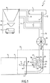
- the second duct 21 is designed to convey vapors and / or bitumen dust from the central 1, and more specifically from the collection means 6 (and thus forming said second portion), to the flame 4 of in order to burn them, that is to say to destroy them, even in the preferential event where the air (or the oxygen contained in the air) which surrounds them does not serve as an oxidizer, as illustrated in FIG. figure 2 .
- the first portion advantageously bathes, upstream of the burning head 3, and in particular within the oxidizer supply line 38 and / or the first conduit 20, in the oxidant (formed for example by air or preferably the oxygen contained in the air or another source of pure oxygen or not), the first portion immersed in the oxidant being further downstream conveyed by the oxidizer feed pipe 38 to the burn head 3, to be subsequently destroyed by a combustion reaction consuming said oxidant and said fuel and producing the flame 4, while the second portion is preferably conveyed directly into the furnace 2, optionally up to the flame 4 or in the vicinity of the latter so as to be destroyed by said flame 4 and / or the heat generated by the latter, even without being in contact with the oxidant before it has been consumed in the reaction. n combustion producing said flame 4, although such an alternative is possible.
- the second conduit 21 comprises a secondary outlet mouth 43 opening into and located in the furnace 2, said secondary outlet mouth 43 being optionally designed, as illustrated in FIG. figure 2 to bring the second portion into or near the flame 4 so as to be burned, that is to say destroyed or neutralized by the latter.
- Said secondary outlet mouth 43 may thus optionally comprise a conical piece 44 positioned around the primary outlet mouth 42, in the furnace 2, to concentrate a charged air flow of said secondary portion (the third flow F3, as it will be seen below) as close as possible to the flame 4.
- Such an advantageous configuration where at least part (or all according to the operating mode of the burner 32) vapors and / or bitumen dust from the coating plant 1 (and more precisely from the collection means 6) is driven to destruction via the first conduit 20 and the oxidizer supply line 38, while another part (zero or non-zero) vapors and / or dust bitumen is injected or reinjected directly into the furnace 2 (and more precisely inside the casing 5, or even in the region of the flame 4) via the second duct 21, is particularly effective for causing the burning, that is to say destruction here by means of a combustion, vapors and / or dust bitumen from the plant 1, thus avoiding their escape outside the latter and pollution afferent.
- the burner 32 of the invention it is possible to avoid certain pollution (or at least greatly limit the risk and / or the importance thereof) associated with an untimely release of blue smoke in the atmosphere, by destroying them within or near the asphalt plant 1.
- said first and second conduits 20, 21 are intended to be connected (in particular fluidly) to a part of the collection means 6, in particular to the same downstream part of the collection means 6, for example a downstream portion of the single main collection conduit 16, in particular a downstream end thereof, as illustrated in FIG. figure 1 or at a downstream portion of the primary primary collection ducts 17 and secondary 18, in particular the branch 19, as illustrated in FIG. figure 2 .
- said first and second conduits 20, 21 are respectively intended to be connected (in particular fluidically) to a respective downstream portion (for example a downstream end) of the primary primary collection ducts 17 and secondary 18, said primary primary collection ducts 17 and secondary 18 being for example not in fluid communication (direct) with each other.
- the burner 32 also comprises a means for establishing a second and / or a third gas flow F2 , F3 for circulating the vapors and / or dust of bitumen within said first conduit 20 and / or or said second duct 21, the second gas flow F2 thus also being advantageously circulated within the oxidizer supply duct 38 by the means for establishing a second and / or a third gas flow F2 , F3 .
- the means for establishing a second and / or a third gas flow F2 , F3 makes it possible to set the air in motion and / or to promote its flow inside said first duct 20 (and therefore also by extension preferably inside the oxidizer supply duct 38 ) and / or said second conduit 21, the air thus set in motion for driving the vapors and / or dust bitumen from the coating plant 1.
- the air set in motion within the first duct 20 will also be set in motion within the oxidizer supply duct 38, since the latter is connected (preferably fluidly) to the first duct 20.
- an air flow in particular the second gas flow F2
- the first conduit 20 forms a specific upstream portion of the oxidizer supply line 38 , or that the latter forms a specific downstream portion of the first conduit 20.
- said means for establishing a second and / or a third gas stream F2 , F3 also makes it possible to establish a first gas stream F1 feeding upstream said second gas stream F2 and / or said third gas stream F3 .
- the means for establishing a second and / or a third gas flow F2 , F3 is also designed to circulate the vapors and / or dust bitumen within the collection means 6.
- the means for establishing a second and / or a third gas flow F2 , F3 makes it possible to set the air in motion and / or to promote the flow inside said means of collecting 6, thus forming the first gaseous flow F1 , the air thus set in motion for driving vapors and / or bitumen dust from the central 1 and collected by said collection means 6 via the collection points, and in particular those at that time inside the collection means 6, towards said first conduit 20 and / or said second conduit 21.
- said vapors and / or bitumen dust collected and the air which drives them pass successively from said collection means 6 to the first conduit 20. and / or to the second duct 21 in a continuous manner, so as to form a continuous flow of more or less charged air (one can even say polluted) in vapor and / or dust of bitumen between the upstream of the collecting means 6 ( in particular one or more collection points) and the downstream of the first conduit 20 (and by extension the downstream of the oxidizer supply line 38) and / or the second conduit 21.
- the first conduit 20 opens downstream in a feed (especially in oxidizer) of the burner 32 and more preferably, as we have seen, in the oxidizer feed line 38.
- the second conduit 21 preferably opens downstream directly into the furnace 2.
- said means for establishing a second and / or a third gas flow F2 , F3 comprises at least one primary ventilation means 22 of said first duct 20 (and therefore also preferably also of said supply duct oxidant 38) and / or said second duct 21, said primary ventilation means 22 being positioned upstream of said first and second ducts 20, 21.
- Said primary ventilation means 22 is therefore in particular designed to ventilate said collection means 6, said first conduit 20 (and therefore by extension said oxidizer supply line 38), and / or said second conduit 21.
- the primary ventilation means 22 is in particular designed to circulate (that is to say put in motion) the air on the one hand within the collection means 6, the first conduit 20 (and therefore by extension of said oxidant supply line 38) and / or the second conduit 21, and secondly inside said one or more collection ducts primary 12, secondary 13, tertiary 14 and / or quaternary 15, as well as according to a first embodiment illustrated in FIG. figure 1 within the single main collection line 16, or according to a second embodiment illustrated in FIG. figure 2 within said primary primary collection ducts 17 and secondary 18.
- said primary ventilation means 22 comprises at least a first primary fan 35.
- said primary ventilation means 22 further comprises a second primary ventilator 36.
- said first primary blower 35 is connected to said single main collection duct 16, said first primary blower 35 being for example mounted on or in said single main collection duct 16, and preferably being the only blower of the primary ventilation means 22 .
- said primary ventilation means 22 comprises at least said first and second primary ventilators 35, 36 which are distinct, and which are each connected to one of said primary and secondary primary collection conduits 17.
- each of the first primary ventilators and second primary fans 35, 36 is mounted on or in a different one of said primary primary collection ducts 17 and secondary 18.
- the primary ventilation means 22 comprises as many fans as there are collection ducts 12, 13, 14, 15, each fan being connected to a respective collection ducts 12, 13, 14, 15.
- the primary ventilation means 22 advantageously comprises as many fans as there are main ducts of collection 16, 17, 18 separately connected (particularly fluidically) directly or indirectly (for example via the branch 19) to said first and second conduits 20, 21, each fan is connected to a respective one of the main collection ducts 16, 17, 18.
- the primary ventilation means 22 comprises at least two primary fans 35, 36 or more, said primary fans 35, 36 each having substantially the same configuration and / or being arranged in parallel.
- the collection ducts 12, 13, 14, 15 collect (that is to say, join fluidically) upstream of the primary ventilation means 22.
- the primary ventilation means 22 constitutes a part of the burner 32.
- said primary ventilation means 22 constitutes, without necessarily invalidating the preceding sentence, part of the coating plant 1, in particular a portion of a pre-existing coating plant that would have been constructed including ventilation means that can be adapted to operate in a manner similar or similar to the possible primary ventilation means 22 of the invention.
- the primary ventilation means 22 form part of the means 6, which means that the collection means 6 comprises the primary ventilation means 22, which it shares for example with the burner 32 and / or the rest of the central 1.
- said first gas stream F1 has, for example within the collection means 6, a primary flow Q1 .
- the first gas stream F1 is a flow of air circulating advantageously within the collection means 6 and which comprises all of the circulating gas stream (at a given time or during a given period) within the collection means 6 , said primary flow Q1 thus advantageously comprising all of the flow of air in the collecting means 6.
- the first gaseous flow F1 is formed by all the different gaseous flows circulating in the different collection ducts 12, 13 , 14, 15, and / or is formed by the gaseous flow flowing in the single main collection duct 16, or else is formed by the two partial gas flows F'1 , F "1 flowing one in the duct primary collection main 17 and the other in the main secondary collection duct 18, and / or still is formed by the gaseous flow flowing in the branch 19.
- said primary ventilation means 22 is designed to maintain said primary rate Q1 substantially constant, that is to say in particular stable over time.
- the primary ventilation means 22 is advantageously designed to circulate (that is to say put in motion) the air within the collection means 6, the first conduit 20 (and therefore by extension of said conduit d supply of oxidant 38) and / or second conduit 21 in a continuous and regular manner, either by drawing external air or conditioned, or by setting in motion the polluted air (that is to say charged with vapor and / or bitumen dust collected), or by combining the two actions, so that the flow of air flowing through the collection means 6 (and preferably causing the vapor and / or bitumen dust collected) is constant over time.
- Such a configuration has the particular advantage of ensuring a continuous and regular collection or extraction of vapors and / or dust bitumen from the collection points of the plant 1.
- said primary ventilation means 22 is designed to " extract In constant flow and at the same primary flow rate Q1 constant the air laden with blue fumes (that is to say vapors and / or bitumen dust) outside the means for storing bituminous mixes 8, the means for storing bitumen 7, from the evacuation zone 9 bituminous mixes, and / or means for producing bituminous mixes, for bringing at least a first portion to the oxidant feed line 38 via the first conduit 20 and / or at least a second portion directly into the the oven 2 via the second duct 21.
- said primary ventilation means 22 is designed (or adjusted) to maintain the primary flow rate Q1 at a value of between 5,000 and 40,000 m 3 / h, more preferably between 10,000 and 20,000 m 3 / h, for example equal to approximately 18 200 m 3 / h and preferably constant, these flow rate values being given for illustrative and not limiting.
- the value of the primary flow rate Q1 is advantageously adjusted according to various parameters, such as, for example, the size of the equipment of the coating plant 1, the desired operating mode of the burner 32 and / or the plant 1, the speed of production of bituminous mixes and / or drying of aggregates, etc.
- said second flux F2 has a secondary flow rate Q2a input of said first conduit 20.
- the second gas flow F2 is a flow of air flowing within the first conduit 20, and it comprises the entire gas flow circulating (at a given time and / or during a given period) within the first conduit 20.
- Said secondary flow Q2a inlet therefore advantageously comprises the entire air flow at the entrance or just after the entry of the first duct 20, that is to say the flow of air in an upstream part (or even the most upstream part) of said first duct 20.
- said third flow F3 has a tertiary flow Q3 within said second 21.
- the third gas flow F3 is a flow of air flowing in the second duct 21 and comprising the entire flow of gas that circulates (at a given moment and / or during a given period) within the second duct 21, said tertiary flow Q3 thus advantageously comprising all of the flow of air within the second conduit 21.
- the second flow F2 also flows within the oxidizer supply line 38 where it has a flow rate at less equal (or higher in certain situations, as will be seen below) to the inlet air flow Q2a .
- the burner 32 comprises a regulating means 23 of said secondary inlet flow Q2a and said tertiary flow Q3 .
- the regulating means 23 is therefore advantageously designed to control, that is to say increase or decrease at will, the secondary input flow Q2a and the tertiary flow Q3 , knowing that in principle, the sum of the secondary input flow Q2a and the tertiary flow Q3 is preferably substantially equal to the primary flow rate Q1 , regardless of the operating mode of the burner 32.
- said regulating means 23 controls said secondary input flow Q2a and said tertiary flow Q3 interdependently, so that a reduction of the secondary input flow Q2a causes a substantially proportional increase of said tertiary flow Q3 and vice versa.
- said regulation means 23 comprises a first and a second valve system (s) 24, 25 respectively equipping said first and second conduits 20, 21.
- said first and second valve systems ( s) 24, 25 each comprise at least one valve or a plurality of valves positioned in a complementary manner, and said valves being for example butterfly type.
- said valves may optionally be likened to flaps.
- the first valve system 24 instead equips the oxidizer supply line 38.
- said regulating means 23 is adapted to manage said first and second valve systems 24, 25 interdependently, so that when the valve (s) of the first valve system (s) 24 are in the 100% open position, the secondary input flow Q2a is then substantially equal to the primary flow rate Q1 , and when the valve (s) of the second valve system (s) 25 are in the 100% closed position, the tertiary flow Q3 is substantially zero, and vice versa.
- said regulating means 23 comprises at least one servomotor (not illustrated) designed to drive alone said first and second valve systems (s) 24, 25 which are then preferentially in mechanical interdependence, that is to say in mechanical connection with each other, so that an opening movement of the valve (s) of one mechanically drives a equivalent closing movement of the valve (s) of the other and vice versa.
- said regulating means 23 comprises at least a first and a second servomotor (not illustrated) which are designed to respectively drive said first and second valve systems (24, 25), which are then advantageously in electronic interdependence, that is to say in electronic connection with each other via said two servomotors, so that an opening movement of the valve (s) of one of the two valve systems (s) 24, One of the servomotors actuates an equivalent closing movement of the or the valve (s) of the other of the two valve systems (s) 24, 25 controlled by the other of said servomotors, and vice versa.
- control means advantageously makes it possible to manage the distribution of the first stream F1 between the first duct 20 and the second duct 21, or in other words to control the distribution of the primary flow rate Q1 between the secondary inlet flowrate Q2a and tertiary flow Q3 .
- This distribution can, as we have seen, just as well be advantageously managed mechanically with a single servomotor driving all of the regulating means 23 and in particular the first and second valve systems (s) 24, 25, that electronically controlled, each of the first and second valve systems 24, 25 being driven by a separate servomotor.
- the burner 32 can operate in different modes of operation.
- the burner 32 advantageously has different power levels.
- the burner 32 has a maximum power level where it uses substantially all, or 100%, of its maximum power, and requires, to operate, a maximum combustion air flow having a maximum oxidant flow Qc max which is for example equal to about 28,000 m 3 / h.
- the burner 32 has at least one intermediate power level where it uses a fraction of its maximum power, and requires, to operate, an intermediate combustion air flow having an intermediate oxidizer flow Qc int .
- the burner 32 of the invention is a proportional burner, that is to say that it is designed to operate according to fully adjustable modes of operation, to allow to adjust at will the power used by the burner 32 over a continuous range of operating points.
- the burner 32 can advantageously operate according to an infinity of operating points each corresponding to a fraction of the maximum power of the burner 32.
- the oxidizer flow (intermediate Qc int or maximum Qc ma x ) necessary for the proper operation of the burner 32 is proportional to the power used burner 32, the latter is therefore advantageously chosen, that is to say adjustable (between 0 and 100% of the maximum power of the burner 32), and not relative to a fixed power level or predetermined, although it is also quite possible that the burner 32 has predetermined preferred power levels while remaining adjustable if needed.
- the regulating means 23 adjusts the secondary flow rate at the inlet Q2a as a function of the power level of the burner 32.
- the regulating means 23 adjusts the secondary flow rate at the inlet Q2a so that it is substantially equal to the intermediate oxidizer flow rate Qc int , the intermediate combustion air flow is also advantageously formed by the second flow F2 .
- the threshold power level of the burner 32 is for example greater than the first and second intermediate power levels.
- the regulating means 23 Preferably, below the threshold power level of the burner 32, the regulating means 23 also adjusts the tertiary flow rate Q3 as a function of the power level of the burner 32, and / or as a function of the secondary inlet flow rate Q2a .
- the primary flow Q1 is intended to remain, regardless of the power level of the burner 32, substantially constant, for example equal to 18 200 m 3 / h.
- the regulation means 23 adjusts on the one hand the secondary input rate Q2a so that it is substantially equal to the bit rate.
- intermediate oxidant Qc int necessary for the operation of the burner 32 at the first intermediate power level the secondary flow rate at the input Q2a then being for example equal to 5 600 m 3 / h
- the regulation means 23 adjusts advantageously the secondary flow rate Q2a substantially in proportion to the power level of the In particular, when the burner 32 operates below the power threshold level, the regulating means 23 will adjust the secondary flow rate at the inlet Q2a so that it is substantially equal to the necessary airflow of the oxidizer. so that the burner 32 produces said flame 4, that is to say the intermediate oxidizer flow Qc int , the second flow F2 then preferably having the same flow downstream and upstream of the first conduit 20 and upstream and downstream. downstream of the oxidizer supply line 38.
- an increase (or a decrease) in the power of the burner 32 causes an increase (or a decrease) in the secondary input flow Q2a by the regulating means 23.
- the tertiary flow Q3 is preferentially non-zero, and the third flow F3 flows to the furnace 2 by means of the intermediate of the second conduit 21, causing some of the vapor and / or dust bitumen collected (eg the second portion).
- the first stream F1 preferably leaves the collection means 6 to be distributed between the second stream F2 and the third stream F3 , said second stream F2 and the third stream F3 each having a rate which is advantageously non-zero.
- Such a configuration, where the regulating means 23 adapts the secondary flow rates at the inlet Q2a and tertiary Q3 with respect to the operating power of the burner 32, is particularly advantageous, because whatever the power level of the burner 32 (below the threshold level), the burner 32 (and by extension the coating plant on which it is adapted) is intended to burn, that is to say destroy by means of combustion, at least a portion of the vapors and / or dust collected (except of course if the power used of the burner 32 is zero), and without negative impact on the asphalt production capacity of the plant 1.
- the regulating means 23 adjusts the secondary input flow rate Q2a so that it is substantially equal to the primary flow rate Q1 and / or constant, said flow rate tertiary Q3 being substantially zero.
- the first valve system (s) 24 is in a maximum open position, while the second valve system (s) 25 is in position of maximum closure, the secondary input flow Q2a then being maximum (and substantially constant and / or equal to the primary flow Q1 , ie for example 18 200 m 3 / h) and the tertiary flow Q3 then being minimal (preferably substantially zero).
- the whole of the first stream F1 within the collection means 6 circulates to form advantageously the whole of the second stream F2 within the first conduit 20.
- said means for establishing a second and / or a third gas flow F2 , F3 further comprises secondary ventilation means 26 of said first duct 20 and / or said duct.
- said secondary ventilation means 26 being intended to equip said first conduit 20 and / or said oxidizer supply line 38, and preferably positioned downstream of said collection means 6 and / or downstream of said control means 23 (more particularly downstream of the first valve system (s) 24).
- the secondary ventilation means 26 advantageously equips said first conduit 20 and / or said oxidizer supply line 38.
- said secondary ventilation means 26 is designed to circulate (thus move) the air at least within the first conduit 20 and / or said oxidizer supply line 38, intermittently or continuously according to the power level of the burner 32, in particular by drawing outside or conditioned air and / or by putting in motion the polluted air (that is to say, charged with vapors and / or bitumen dust collected), plus preferentially by combining the two actions.
- said secondary ventilation means 26 is designed to circulate (thus move) the air at least within the first conduit 20 and / or said oxidizer supply line 38, intermittently or continuously according to the power level of the burner 32, in particular by drawing external air or conditioned air which it injects into the first conduit 20 and / or of said oxidant supply line 38 and / or by setting in motion the air polluted (that is to say loaded with vapors and / or bitumen dust collected), more preferably by combining the two actions.
- said secondary outlet flow Q2b comprises the totality of the air flow at the outlet or just before the exit of the oxidizer supply line 38, plus preferably the entire air flow rate in a downstream portion of the oxidizer feed pipe 38, and even more preferably the entire air flow in a portion at or just before the burning head 3.
- the burner 32, and more precisely said secondary ventilation means 26, is thus advantageously designed to allow the introduction into said oxidant supply line 38 (and / or optionally a downstream portion of the first duct 20) and preferably well upstream of the burning head 3, an external air flow or conditioned F ext preferentially formed in whole or in part of oxidizer (and preferably free of vapors and / or dust bitumen from the central 1), which is particularly necessary for the production of the flame 4.
- the burner 32 is preferably designed to allow the adjustment of the gas flow rate (secondary flow output Q2b ) circulating within said oxidizer supply line 38 so that it is greater than the gas flow rate (secondary flow rate at the inlet Q2a ) flowing in the first duct 20, the difference being formed by the addition of the external air flow or conditioned F ext .
- the latter can obviously be optionally formed of air gases in different proportions, for example enriched with oxygen (more than 20.95% for example, especially more than 30% molar fraction of oxygen), or charged with of one or more other oxidants.
- the burner 32 and / or the central unit 1 thus comprises at least one main collection duct 16, 17, 18 (as described above) in which said first and second mixed portions circulate and which opens onto said first and second portions second conduits 20, 21 (and in particular fluidly communicates therewith), said first and second portions being advantageously separated at the boundary between the main collection duct 16, 17, 18 on the one hand and the first and second conduits 20, 21 on the other hand, as illustrated in FIGS.
- the burner 1, and more precisely the secondary ventilation means 26, thus advantageously makes it possible to inject the oxidant at will, in particular in the form of the external or conditioned air flow F ext , into an upstream part of the supply duct. 38, substantially at the boundary between said oxidant supply line 38 and said first conduit 20, the position of the oxidant injection (preferably in the form of the external air flow or conditioned F ext ) thus defining possibly said limit.
- said first and second portions are separated from each other, respectively within the first conduit 20 (and then the oxidizer supply line 38) on the one hand and the second conduit 21 on the other hand at least between the burning head 3 where they are burned (and therefore destroyed) and the at least one main collection duct 16, 17, 18 from which they are derived.
- the burner 32 of the invention can operate continuously regardless of the state of the coating plant 1.
- the secondary ventilation means 26 will adjust the secondary output flow Q2b so that it is substantially equal to (or alternatively greater than) the flow rate. necessary air of oxidizer for the burner 32 to produce said flame 4, the second flow F2 then having different flow rates downstream and upstream of the first (the secondary flow rate at the inlet Q2a then being smaller than the secondary flow rate at the outlet Q2b ).
- the secondary ventilation means 26 preferably adjusts the external air flow or conditioned Q ext as a variable component of the secondary output flow Q2b , so that the secondary flow rate at the outlet Q2b is substantially equal (or alternatively greater) than the necessary airflow of oxidizer for the burner 32 to function properly, the secondary flow component at the inlet Q2a of the secondary outlet flow Q2b remaining advantageously constant .
- the secondary ventilation means 26 adjusts the secondary output flow Q2b proportionally at the power level of the burner 32, while the secondary input flow Q2a remains constant and substantially equal to the primary flow Q1 , and the tertiary flow Q3 remains substantially zero.
- an increase (or a decrease) in the power of the burner 32 causes an increase (or a decrease) in the secondary output flow Q2b by the secondary ventilation means 26.
- the tertiary flow Q3 is preferably zero, and the third flow F3 is preferably nonexistent or negligible.
- the first flow F1 preferably leaves the collection means 6 to enter the first conduit 20 (and then into the supply line of oxidizer 38) where it forms the second stream F2 , to which is added the external air flow or conditioned F ext from the secondary ventilation means 26 and having the external air flow or conditioned Q ext .
- Such a configuration, in which the secondary ventilation means 26 fits in particular with respect to the operating power of the burner 32, is particularly advantageous. Because regardless of the power used of the burner 32 (beyond the threshold level), the latter (and by extension the coating plant on which it is adapted) is able to burn, that is to say destroy, at least some, if not all, of the vapors and / or dust collected, without having a negative impact on the bitumen production capacity of the power plant 1.
- the threshold power level of the burner 32 is for example less than the third intermediate power level.
- the regulation means 23 adjusts on the one hand the secondary input rate Q2a so that it is substantially maximum and / or substantially equal to the primary flow Q1 , for example to 18 200 m 3 / h, and secondly the tertiary flow rate Q3 so that it is substantially zero, while the secondary ventilation means 26 introduces a flow rate of external air or conditioned Q ext which will add to the secondary flow rate Q2a input within the second flow F2 to form (and adjust) the secondary flow output Q2b , so that the latter is substantially equal to the oxidizer flow necessary for the correct operation of the burner 32, and in particular equal to either the intermediate oxidant flow Qc int , which is for example equal to about 22 400 m 3 / h, or the maximum oxidant flow Qc max , which is for example the equals about 28,000 m 3 / h.
- the secondary ventilation means 26 is advantageously designed to introduce (that is to say inject) the flow of outside air or conditioned Q ext into the first conduit 20 and / or the oxidizer supply line. 38, and more advantageously upstream of the oxidizer feed pipe 38 for supplying the latter and subsequently the flame 4 with air (more preferably oxygen dioxide contained in the air, and therefore with oxidant).
- the external air or conditioned air flow Q ext supplied by the secondary ventilation means 26 is advantageously equal to the secondary output flow rate.
- the secondary fan 37 of the secondary ventilation means 26 is designed to adjust itself the primary rate of flow of outside air or conditioned Q ext , thus adjusting the secondary output flow Q2b , and this according to the mode of operating the burner 32 (that is to say the operating power of the burner 32) and / or the secondary flow rate Q2a input authorized by the control means 23.
- the secondary ventilation means 26 comprises at least one adjustment means 33 for the external air flow or Q ext , said adjustment means 33 being advantageously distinct from the secondary ventilator 37.
- the secondary fan 37 is advantageously designed to allow a constant flow mode of operation.
- the secondary ventilator 37 advantageously has at least one operating mode in which it extracts a constant air flow from an external source in order to inject it into the first duct 20 and / or the supply duct.
- said adjustment means 33 comprises a third valve system (s) 34, which comprises for example at least one valve or a plurality of valves, said valves being in particular butterfly type. Of course, said valves may optionally be likened to flaps.
- said adjusting means 33 (and more precisely said third valve system (s) 34) is substantially positioned between the secondary fan 37 on the one hand and the first conduit 20 and / or the oxidizer supply line 38 of on the other hand, and more precisely at the interface of the latter.
- the secondary ventilation means 26, and more specifically the secondary ventilator 37 advantageously has at least one mode of operation in which it extracts a constant air flow from an external source in order to inject it into the first duct 20 and / or or the oxidizer supply line 38, the adjustment means 33 making it possible to vary the flow rate of outside or conditioned air Q ext effectively introduced into the first duct 20 and / or the oxidizer supply duct 38.
- the adjustment means 33 is designed to adjust itself the external air flow or conditioned Q ext (provided by the secondary ventilation means 26 which ventilates at constant flow or not) according to the operating mode of the burner 32 (that is to say the operating power of the burner 32) and / or the secondary flow rate at the inlet Q2a authorized by the control means 23.
- the third valve system ( s) 34 is designed to limit the primary flow rate of outside air or conditioned Q ext to a fraction of the air flow extracted from an external source by the secondary fan 37.
- the collection means 6 comprises a collection control means 27, preferably upstream of the primary ventilation means 22, and for example formed by one or more valve systems 28, 29, 30, 31 within ( i.e., inside) one or more of said collection conduits 12, 13, 14, 15, said collection regulating means 27 being designed to regulate, i.e., limit, the collection of vapors and / or dust from, for example, bitumen storage means 7, bituminous mix storage means 8, discharge zone 9, and / or bituminous mix production means.
- the figure 4 illustrates an example of a burner 32 according to the invention where the first valve system 24 is in the fully open position and the second and third valve systems 25, 34 are in the fully closed position, the tertiary flow of the third flow F3 being therefore zero, while the secondary flow rate at the inlet Q2a is substantially equal to the secondary flow rate at the outlet Q2b , and the external or conditioned air flow Q ext of the external air flow or conditioned F ext is meanwhile zero.
- Such a configuration given by way of illustrative and nonlimiting example, is suitable in the case where the burner 32 operates at the power threshold level, for example at 65% of its power.
- the invention also relates as such, according to a second aspect, a coating plant 1 for the manufacture of hot bituminous mix from aggregates and bitumen, said plant 1 comprising an oven 2 and being characterized in that it further comprises at least one burner 32 as described above (and optionally as described below), said burner 32 advantageously equipping said furnace 2.
- a coating plant 1 for the manufacture of hot bituminous mix from aggregates and bitumen, said plant 1 comprising an oven 2 and being characterized in that it further comprises at least one burner 32 as described above (and optionally as described below), said burner 32 advantageously equipping said furnace 2.
- the foregoing description concerning the burner 32 therefore also applies to the coating plant 1 according to the invention.
- the invention also relates, as such, according to a third aspect, to a process for the depollution of a coating plant 1 intended to manufacture hot bituminous mixes from aggregates and bitumen, the depollution process being preferably implemented within the coating plant 1 described above, and / or with the aid of the burner 32 (advantageously equipping the central 1, and in particular the furnace 2 of the latter) previously described.
- the burner 32 and / or the coating plant 1 therefore also applies to the depollution process according to the invention.
- the depollution process advantageously makes it possible to limit or even completely avoid the discharges of vapors and / or dust from bitumen, or blue fumes, into the atmosphere, in particular by organizing their destruction by burning within the coating plant 1 .
- said central unit 1 comprises an oven 2, preferably as described above.
- the depollution process comprises at least one step of equipping said furnace 2 with a burner 32, the latter being advantageously as described above, that is to say that it comprises a burning head 3 and an oxidant feed line 38 to the burn head 3 for produce at the latter a flame 4 for heating the interior of said oven 2.
- said process comprises at least one step of collecting vapors and / or bitumen dust from the bitumen used by the plant 1 and / or bituminous mixes manufactured by the latter.
- said collecting step is performed with a collection means 6, which is preferably as described above.
- the depollution process further comprises a step of supplying the oxidant supply pipe 38 upstream of the burning head 3, to vapors and / or bitumen dust resulting from the bitumen used by the central 1 and / or bituminous mixes manufactured by the latter, said vapors and / or bitumen dust having previously been advantageously collected during said collection step.
- said method also comprises a step of conveying vapors and / or bitumen dust from the bitumen used by the plant 1 and / or bituminous mixes manufactured by the latter in the furnace 2, said vapors and / or or bitumen dust having previously been advantageously collected during said collection step.
- at least a part (non-zero or zero depending on the operating mode of the burner 32, for example formed by the second portion) vapors and / or dust bitumen from the central 1 ( and having been collected) is advantageously introduced directly within (that is to say inside) the furnace 2 without passing through the oxidizer supply line 38.
- at least part of the vapor and / or bitumen dust collected is conveyed, that is to say transferred or displaced, in a flame 4 produced by the burner 32, as previously described.
- said feeding and routing steps are performed respectively via at least a first and a second conduit 20, 21, which are advantageously as described above.
- the step of supplying the oxidant supply line 38 with vapor and / or bitumen dust collected advantageously comprises the introduction (that is to say the transfer) of vapors and / or dust of bitumen lying within the first conduit 20 within said oxidizer supply line 38, said vapors and / or bitumen dust passing from the first conduit 20 to the oxidizer supply line 38 together with the air ( more preferably the dioxygen contained in the air) to which they are mixed and which will serve as oxidant to the flame 4.
- the process advantageously comprises a step of establishing a second and / or a third gas stream F2 , F3 , preferably as described above, for circulating the vapors and / or dust of bitumen respectively during said steps of feeding and / or routing.
- said step of establishing a second and / or a third gas flow F2 , F3 comprises at least one primary step of ventilating said first duct 20 (and therefore by extension, also preferably of the supply duct of oxidant 38) and / or said second duct 21, as well as advantageously of said collection means 6.
- Said primary ventilation step is preferably carried out with at least one primary ventilation means 22, as described above, the latter being by example positioned upstream of said first and second conduits 20, 21 (and therefore also upstream of the oxidizer supply line 38).
- a first gas stream F1 is also established, the latter supplying upstream said second gas stream F2 and / or said third gas stream F3 .
- the first gaseous flow F1 is advantageously upstream of said second and third gas stream F2 , F3 , said second and third gas stream F2 , F3 is preferably neither downstream nor upstream of each other.
- said first gas flow F1 has a primary flow rate Q1 , as described above, for example within the collection means 6. More advantageously, during said primary ventilation step, said primary flow rate Q1 is maintained substantially constant. , as described above, in order to allow in particular a continuous collection of vapors and / or dust bitumen from the central 1.
- said second stream F2 has a secondary flow F2 at the inlet Q2a of said first conduit 20 and said third flux F3 has a tertiary flow Q3 within said second conduit 21. More preferably, the method comprises a step regulating said secondary input flow Q2a and said tertiary flow Q3 .
- said regulation step is carried out with a regulating means 23, as previously described, which comprises for example a first and a second valve system (s) 24, 25 respectively equipping said first and second conduits 20, 21, as previously described.
- a regulating means 23 comprises for example a first and a second valve system (s) 24, 25 respectively equipping said first and second conduits 20, 21, as previously described.
- said valves may optionally be likened to flaps.
- the first valve system 24 instead equips the oxidizer supply line 38.
- control (particularly with the aid of the regulating means 23) said input secondary flow Q2a and said tertiary flow Q3 interdependent, so that a reduction of the secondary flow input Q2a causes a substantially proportional increase in said tertiary flow Q3 and vice versa.
- the burner 32 has different power levels.
- the secondary flow rate at the inlet Q2a is adjusted as a function of the power level of the burner 32, preferably by means of 23.
- This mode of operation of the burner 32 corresponds in particular to the power levels of this last where the primary ventilation means 22 circulates the first gas stream F1 whose primary flow rate Q1 is greater than the combustion requirements of the burner 32.
- the secondary input flow Q2a is adjusted (preferably by means of the regulation means 23) so as to it is substantially equal to the primary flow rate Q1 and / or constant, said tertiary flow Q3 being substantially zero.
- said step of establishing a second and / or a third gas stream F2 , F3 further comprises a secondary step of ventilating said first conduit 20 and / or said oxidant supply line 38, said secondary ventilation step being advantageously carried out with secondary ventilation means 26, as previously described, and which is preferably intended to be positioned downstream of said collection means 6, said regulation means 23, and / or said means of primary ventilation 22.
- an external or conditioned air flow F ext is introduced (that is to say injected) into the first conduit 20 and / or the oxidizer supply line 38, in particular with the aid of the secondary ventilation means 26 which advantageously comprises a secondary ventilator 37, preferably of the centrifugal type.
- Said external air or conditioned flow F ext advantageously has an external air flow or conditioned Q ext as mentioned above.
- said second flux F2 has a secondary output flow Q2b of said oxidant supply line 38, as described above.
- the secondary output flow Q2b is adjusted, preferably by means of the secondary ventilation means 26, in function of the power level of the burner 32. More preferably, beyond the power threshold level of the burner 32, during said secondary ventilation step, the flow rate is preferably adjusted with the aid of the secondary ventilation means 26.
- outside air or conditioned Q ext according to the power level of the burner 32, the outside air flow or conditioned Q ext here forming a variable component of the secondary output flow Q2b, the secondary input flow Q2a here forming another constant component of the secondary output flow Q2b , the adjustment of the flow rate of external air or conditioned Q ext allowing to adjust in practice the secondary flow output Q2b .
- This mode of operation of the burner 32 corresponds in particular to the power levels of the latter where the primary ventilation means 22 circulates the first gas flow F1 whose primary flow rate Q1 is lower than the combustion requirements of the burner 32, the means of secondary ventilation 26 to bring the gas stream "missing " to allow the burner 32 to produce combustion with enough oxidant (and therefore to produce the flame 4 satisfactorily).
- the process of the invention is carried out continuously, and several (or all) of the process steps are carried out concomitantly with different fractions of vapors and / or bitumen dust.
- Such a configuration has the particular advantage of ensuring a continuous and regular collection or extraction of vapors and / or dust bitumen from the central 1 (and more precisely the collection points).
- said primary ventilation means 22 is designed to " extract " continuously and at a constant primary flow rate Q1 the air charged with blue fumes outside the bituminous mix storage means 8, the bitumen storage means 7, the evacuation zone 9 of the bituminous mixes, and / or the bituminous mix production means, to bring at least a portion (the first portion) to the oxidant feed line 38 via the first conduit 20 and / or at least one other part (the second portion) directly in the furnace 2 via the second conduit 21.
- the principle of the invention lies in sum in the adaptability of the burner 32 equipping the coating plant 1, the burner 32 forming a burning system adjusting to burn the blue fumes from the plant 1 regardless of the power use of the burner 32, and therefore the production speed of the plant 1 and / or that of its blue fumes.
- the burner 32 With low power utilization of the burner 32, particularly at the power threshold level and below, it is preferably carried out the extraction, collection and / or continuous and constant ventilation of blue fumes using only the means primary ventilation 22 to the burner 32, which can therefore burn at least a portion of the blue fumes while it injects the other portion directly into the oven 2, and at higher power, especially beyond the threshold power level , the secondary ventilation means 26 adds to the air circuit enough gas flow (the outside air flow or conditioned F ext ) to ensure the supply of oxidant burner 32 and thus a satisfactory burn or even complete combustive fuel and blue smoke.
- the air circuit enough gas flow the outside air flow or conditioned F ext
Landscapes
- Engineering & Computer Science (AREA)
- Environmental & Geological Engineering (AREA)
- Architecture (AREA)
- Civil Engineering (AREA)
- Structural Engineering (AREA)
- Mechanical Engineering (AREA)
- General Engineering & Computer Science (AREA)
- Application Of Or Painting With Fluid Materials (AREA)
- Road Paving Machines (AREA)
Applications Claiming Priority (1)
| Application Number | Priority Date | Filing Date | Title |
|---|---|---|---|
| FR1852331A FR3079020B1 (fr) | 2018-03-19 | 2018-03-19 | Bruleur de fumees bleues pour la depollution d'une centrale d'enrobage, centrale d'enrobage et procede de depollution associes |
Publications (3)
| Publication Number | Publication Date |
|---|---|
| EP3543607A1 true EP3543607A1 (de) | 2019-09-25 |
| EP3543607B1 EP3543607B1 (de) | 2024-01-24 |
| EP3543607C0 EP3543607C0 (de) | 2024-01-24 |
Family
ID=62816701
Family Applications (1)
| Application Number | Title | Priority Date | Filing Date |
|---|---|---|---|
| EP19163903.8A Active EP3543607B1 (de) | 2018-03-19 | 2019-03-19 | Asphaltmischanlage und entsprechendes abgasbehandlungsverfahren |
Country Status (2)
| Country | Link |
|---|---|
| EP (1) | EP3543607B1 (de) |
| FR (1) | FR3079020B1 (de) |
Citations (5)
| Publication number | Priority date | Publication date | Assignee | Title |
|---|---|---|---|---|
| US5161966A (en) * | 1990-03-10 | 1992-11-10 | H. Krantz Gmbh & Co. | Method and apparatus for burning a pollutants contained in a carrier flow |
| FR2792393A1 (fr) * | 1999-04-16 | 2000-10-20 | Pillard Chauffage | Bruleur a plusieurs combustibles |
| US20040261671A1 (en) * | 2003-06-27 | 2004-12-30 | Taylor Curtis L. | Burner with oxygen and fuel mixing apparatus |
| US20130244187A1 (en) * | 2012-03-19 | 2013-09-19 | Honeywell International Inc. | HIGH EFFICIENCY LOW NOx EMISSION BURNER APPARATUS |
| FR3051203A1 (fr) * | 2016-05-10 | 2017-11-17 | Ermont | Installation et procede d'enrobage de granulats |
-
2018
- 2018-03-19 FR FR1852331A patent/FR3079020B1/fr active Active
-
2019
- 2019-03-19 EP EP19163903.8A patent/EP3543607B1/de active Active
Patent Citations (5)
| Publication number | Priority date | Publication date | Assignee | Title |
|---|---|---|---|---|
| US5161966A (en) * | 1990-03-10 | 1992-11-10 | H. Krantz Gmbh & Co. | Method and apparatus for burning a pollutants contained in a carrier flow |
| FR2792393A1 (fr) * | 1999-04-16 | 2000-10-20 | Pillard Chauffage | Bruleur a plusieurs combustibles |
| US20040261671A1 (en) * | 2003-06-27 | 2004-12-30 | Taylor Curtis L. | Burner with oxygen and fuel mixing apparatus |
| US20130244187A1 (en) * | 2012-03-19 | 2013-09-19 | Honeywell International Inc. | HIGH EFFICIENCY LOW NOx EMISSION BURNER APPARATUS |
| FR3051203A1 (fr) * | 2016-05-10 | 2017-11-17 | Ermont | Installation et procede d'enrobage de granulats |
Also Published As
| Publication number | Publication date |
|---|---|
| FR3079020B1 (fr) | 2020-08-07 |
| EP3543607B1 (de) | 2024-01-24 |
| FR3079020A1 (fr) | 2019-09-20 |
| EP3543607C0 (de) | 2024-01-24 |
Similar Documents
| Publication | Publication Date | Title |
|---|---|---|
| EP0012091B1 (de) | Verfahren und Anlage zur Behandlung von Industriemüll | |
| EP2627739B1 (de) | Vorrichtung zur umwandlung eines brennstoffes | |
| LU85980A1 (fr) | Procede et installation pour l'incineration de combustibiles | |
| EP2153130A2 (de) | Mischeinspritzer mit geringer nox-emission | |
| JP2009085523A (ja) | バーナ | |
| EP3724144B1 (de) | Klinkerproduktionsanlage und verfahren zur klinkerherstellung in einer solchen anlage | |
| WO2015055916A1 (fr) | Brûleur de gaz pauvre | |
| EP2731918A1 (de) | Glasschmelzanlage und verfahren | |
| EP2407716B1 (de) | Brenner für die Aufbereitung von brennbarem saurem Gas, entsprechend angepasster Reaktionsofen und Prozess | |
| EP3543607B1 (de) | Asphaltmischanlage und entsprechendes abgasbehandlungsverfahren | |
| FR2715327A1 (fr) | Système d'injection de boues à incinérer dans un four d'incinération, procédé de fonctionnement, utilisation et four correspondants. | |
| EP1916337A1 (de) | Vorrichtung zur Herstellung eines Asphaltbetons | |
| FR2567624A1 (fr) | Generateur d'air chaud a temperature elevee pour installation de sechage par exemple de briquetterie, de cimenteries ou de produits agricoles, de chauffage de locaux | |
| EP2479493B1 (de) | Verbrennungsvorrichtung, Verbrennungseinheit, die eine solche Verbrennungsvorrichtung umfasst, und Verfahren zum Einsatz einer solchen Verbrennungsvorrichtung | |
| FR2721689A1 (fr) | Procédé et incinérateur pour incinérer les déchets hospitaliers et analogues. | |
| KR102333573B1 (ko) | 아스콘 제조 장치 | |
| WO1996000266A1 (fr) | Procede et dispositif pour traiter a chaud des dechets hospitaliers et analogues | |
| KR100766137B1 (ko) | 음식물 쓰레기로부터 생성된 분체 연료 연소 장치 | |
| EP3813992B1 (de) | Sauerstoffanreicherung und verbrennung eines brennstoffs in form von festpartikeln, die von einem trägergas befördert werden | |
| KR101899583B1 (ko) | 가연성 폐물질을 연료로 활용하는 열회수 소각 연소로의 연소촉진장치 | |
| EP4028692B1 (de) | Verfahren und ofen zum verbrennen von organischen stoffen aus der behandlung von industriellen oder landwirtschaftlichen abfällen oder abwasser, wie schlamm | |
| EP4055325B1 (de) | Verbrennungsvorrichtung | |
| EP0834042B1 (de) | Verfahren und anlage zur verbrennung von krankenhausabfällen | |
| WO2023237496A1 (fr) | Systeme de combustion apte a fonctionner avec un recyclage du gaz de combustion | |
| FR3144645A1 (fr) | Systeme de combustion apte a fonctionner avec un recyclage des fumees de combustion |
Legal Events
| Date | Code | Title | Description |
|---|---|---|---|
| PUAI | Public reference made under article 153(3) epc to a published international application that has entered the european phase |
Free format text: ORIGINAL CODE: 0009012 |
|
| STAA | Information on the status of an ep patent application or granted ep patent |
Free format text: STATUS: THE APPLICATION HAS BEEN PUBLISHED |
|
| AK | Designated contracting states |
Kind code of ref document: A1 Designated state(s): AL AT BE BG CH CY CZ DE DK EE ES FI FR GB GR HR HU IE IS IT LI LT LU LV MC MK MT NL NO PL PT RO RS SE SI SK SM TR |
|
| AX | Request for extension of the european patent |
Extension state: BA ME |
|
| STAA | Information on the status of an ep patent application or granted ep patent |
Free format text: STATUS: REQUEST FOR EXAMINATION WAS MADE |
|
| 17P | Request for examination filed |
Effective date: 20200325 |
|
| RBV | Designated contracting states (corrected) |
Designated state(s): AL AT BE BG CH CY CZ DE DK EE ES FI FR GB GR HR HU IE IS IT LI LT LU LV MC MK MT NL NO PL PT RO RS SE SI SK SM TR |
|
| STAA | Information on the status of an ep patent application or granted ep patent |
Free format text: STATUS: EXAMINATION IS IN PROGRESS |
|
| 17Q | First examination report despatched |
Effective date: 20220704 |
|
| GRAP | Despatch of communication of intention to grant a patent |
Free format text: ORIGINAL CODE: EPIDOSNIGR1 |
|
| STAA | Information on the status of an ep patent application or granted ep patent |
Free format text: STATUS: GRANT OF PATENT IS INTENDED |
|
| INTG | Intention to grant announced |
Effective date: 20230818 |
|
| GRAS | Grant fee paid |
Free format text: ORIGINAL CODE: EPIDOSNIGR3 |
|
| GRAA | (expected) grant |
Free format text: ORIGINAL CODE: 0009210 |
|
| STAA | Information on the status of an ep patent application or granted ep patent |
Free format text: STATUS: THE PATENT HAS BEEN GRANTED |
|
| AK | Designated contracting states |
Kind code of ref document: B1 Designated state(s): AL AT BE BG CH CY CZ DE DK EE ES FI FR GB GR HR HU IE IS IT LI LT LU LV MC MK MT NL NO PL PT RO RS SE SI SK SM TR |
|
| REG | Reference to a national code |
Ref country code: GB Ref legal event code: FG4D Free format text: NOT ENGLISH |
|
| REG | Reference to a national code |
Ref country code: CH Ref legal event code: EP |
|
| REG | Reference to a national code |
Ref country code: DE Ref legal event code: R096 Ref document number: 602019045427 Country of ref document: DE |
|
| REG | Reference to a national code |
Ref country code: IE Ref legal event code: FG4D Free format text: LANGUAGE OF EP DOCUMENT: FRENCH |
|
| U01 | Request for unitary effect filed |
Effective date: 20240222 |
|
| U07 | Unitary effect registered |
Designated state(s): AT BE BG DE DK EE FI FR IT LT LU LV MT NL PT SE SI Effective date: 20240301 |
|
| U20 | Renewal fee for the european patent with unitary effect paid |
Year of fee payment: 6 Effective date: 20240328 |
|
| REG | Reference to a national code |
Ref country code: LT Ref legal event code: MG9D |
|
| PG25 | Lapsed in a contracting state [announced via postgrant information from national office to epo] |
Ref country code: IS Free format text: LAPSE BECAUSE OF FAILURE TO SUBMIT A TRANSLATION OF THE DESCRIPTION OR TO PAY THE FEE WITHIN THE PRESCRIBED TIME-LIMIT Effective date: 20240524 |
|
| PG25 | Lapsed in a contracting state [announced via postgrant information from national office to epo] |
Ref country code: GR Free format text: LAPSE BECAUSE OF FAILURE TO SUBMIT A TRANSLATION OF THE DESCRIPTION OR TO PAY THE FEE WITHIN THE PRESCRIBED TIME-LIMIT Effective date: 20240425 |
|
| PG25 | Lapsed in a contracting state [announced via postgrant information from national office to epo] |
Ref country code: HR Free format text: LAPSE BECAUSE OF FAILURE TO SUBMIT A TRANSLATION OF THE DESCRIPTION OR TO PAY THE FEE WITHIN THE PRESCRIBED TIME-LIMIT Effective date: 20240124 Ref country code: RS Free format text: LAPSE BECAUSE OF FAILURE TO SUBMIT A TRANSLATION OF THE DESCRIPTION OR TO PAY THE FEE WITHIN THE PRESCRIBED TIME-LIMIT Effective date: 20240424 |
|
| PG25 | Lapsed in a contracting state [announced via postgrant information from national office to epo] |
Ref country code: ES Free format text: LAPSE BECAUSE OF FAILURE TO SUBMIT A TRANSLATION OF THE DESCRIPTION OR TO PAY THE FEE WITHIN THE PRESCRIBED TIME-LIMIT Effective date: 20240124 |
|
| PG25 | Lapsed in a contracting state [announced via postgrant information from national office to epo] |
Ref country code: RS Free format text: LAPSE BECAUSE OF FAILURE TO SUBMIT A TRANSLATION OF THE DESCRIPTION OR TO PAY THE FEE WITHIN THE PRESCRIBED TIME-LIMIT Effective date: 20240424 Ref country code: NO Free format text: LAPSE BECAUSE OF FAILURE TO SUBMIT A TRANSLATION OF THE DESCRIPTION OR TO PAY THE FEE WITHIN THE PRESCRIBED TIME-LIMIT Effective date: 20240424 Ref country code: IS Free format text: LAPSE BECAUSE OF FAILURE TO SUBMIT A TRANSLATION OF THE DESCRIPTION OR TO PAY THE FEE WITHIN THE PRESCRIBED TIME-LIMIT Effective date: 20240524 Ref country code: HR Free format text: LAPSE BECAUSE OF FAILURE TO SUBMIT A TRANSLATION OF THE DESCRIPTION OR TO PAY THE FEE WITHIN THE PRESCRIBED TIME-LIMIT Effective date: 20240124 Ref country code: GR Free format text: LAPSE BECAUSE OF FAILURE TO SUBMIT A TRANSLATION OF THE DESCRIPTION OR TO PAY THE FEE WITHIN THE PRESCRIBED TIME-LIMIT Effective date: 20240425 Ref country code: ES Free format text: LAPSE BECAUSE OF FAILURE TO SUBMIT A TRANSLATION OF THE DESCRIPTION OR TO PAY THE FEE WITHIN THE PRESCRIBED TIME-LIMIT Effective date: 20240124 |
|
| PG25 | Lapsed in a contracting state [announced via postgrant information from national office to epo] |
Ref country code: PL Free format text: LAPSE BECAUSE OF FAILURE TO SUBMIT A TRANSLATION OF THE DESCRIPTION OR TO PAY THE FEE WITHIN THE PRESCRIBED TIME-LIMIT Effective date: 20240124 |
|
| PG25 | Lapsed in a contracting state [announced via postgrant information from national office to epo] |
Ref country code: PL Free format text: LAPSE BECAUSE OF FAILURE TO SUBMIT A TRANSLATION OF THE DESCRIPTION OR TO PAY THE FEE WITHIN THE PRESCRIBED TIME-LIMIT Effective date: 20240124 |
|
| PG25 | Lapsed in a contracting state [announced via postgrant information from national office to epo] |
Ref country code: SM Free format text: LAPSE BECAUSE OF FAILURE TO SUBMIT A TRANSLATION OF THE DESCRIPTION OR TO PAY THE FEE WITHIN THE PRESCRIBED TIME-LIMIT Effective date: 20240124 |
|
| PG25 | Lapsed in a contracting state [announced via postgrant information from national office to epo] |
Ref country code: CZ Free format text: LAPSE BECAUSE OF FAILURE TO SUBMIT A TRANSLATION OF THE DESCRIPTION OR TO PAY THE FEE WITHIN THE PRESCRIBED TIME-LIMIT Effective date: 20240124 |
|
| REG | Reference to a national code |
Ref country code: DE Ref legal event code: R097 Ref document number: 602019045427 Country of ref document: DE |
|
| PG25 | Lapsed in a contracting state [announced via postgrant information from national office to epo] |
Ref country code: SK Free format text: LAPSE BECAUSE OF FAILURE TO SUBMIT A TRANSLATION OF THE DESCRIPTION OR TO PAY THE FEE WITHIN THE PRESCRIBED TIME-LIMIT Effective date: 20240124 |
|
| PG25 | Lapsed in a contracting state [announced via postgrant information from national office to epo] |
Ref country code: SM Free format text: LAPSE BECAUSE OF FAILURE TO SUBMIT A TRANSLATION OF THE DESCRIPTION OR TO PAY THE FEE WITHIN THE PRESCRIBED TIME-LIMIT Effective date: 20240124 Ref country code: SK Free format text: LAPSE BECAUSE OF FAILURE TO SUBMIT A TRANSLATION OF THE DESCRIPTION OR TO PAY THE FEE WITHIN THE PRESCRIBED TIME-LIMIT Effective date: 20240124 Ref country code: RO Free format text: LAPSE BECAUSE OF FAILURE TO SUBMIT A TRANSLATION OF THE DESCRIPTION OR TO PAY THE FEE WITHIN THE PRESCRIBED TIME-LIMIT Effective date: 20240124 Ref country code: CZ Free format text: LAPSE BECAUSE OF FAILURE TO SUBMIT A TRANSLATION OF THE DESCRIPTION OR TO PAY THE FEE WITHIN THE PRESCRIBED TIME-LIMIT Effective date: 20240124 |
|
| REG | Reference to a national code |
Ref country code: CH Ref legal event code: PL |
|
| PG25 | Lapsed in a contracting state [announced via postgrant information from national office to epo] |
Ref country code: MC Free format text: LAPSE BECAUSE OF FAILURE TO SUBMIT A TRANSLATION OF THE DESCRIPTION OR TO PAY THE FEE WITHIN THE PRESCRIBED TIME-LIMIT Effective date: 20240124 |
|
| PG25 | Lapsed in a contracting state [announced via postgrant information from national office to epo] |
Ref country code: MC Free format text: LAPSE BECAUSE OF FAILURE TO SUBMIT A TRANSLATION OF THE DESCRIPTION OR TO PAY THE FEE WITHIN THE PRESCRIBED TIME-LIMIT Effective date: 20240124 |
|
| PLBE | No opposition filed within time limit |
Free format text: ORIGINAL CODE: 0009261 |
|
| STAA | Information on the status of an ep patent application or granted ep patent |
Free format text: STATUS: NO OPPOSITION FILED WITHIN TIME LIMIT |
|
| GBPC | Gb: european patent ceased through non-payment of renewal fee |
Effective date: 20240424 |
|
| 26N | No opposition filed |
Effective date: 20241025 |
|
| PG25 | Lapsed in a contracting state [announced via postgrant information from national office to epo] |
Ref country code: GB Free format text: LAPSE BECAUSE OF NON-PAYMENT OF DUE FEES Effective date: 20240424 |
|
| PG25 | Lapsed in a contracting state [announced via postgrant information from national office to epo] |
Ref country code: IE Free format text: LAPSE BECAUSE OF NON-PAYMENT OF DUE FEES Effective date: 20240319 |
|
| PG25 | Lapsed in a contracting state [announced via postgrant information from national office to epo] |
Ref country code: IE Free format text: LAPSE BECAUSE OF NON-PAYMENT OF DUE FEES Effective date: 20240319 Ref country code: GB Free format text: LAPSE BECAUSE OF NON-PAYMENT OF DUE FEES Effective date: 20240424 Ref country code: CH Free format text: LAPSE BECAUSE OF NON-PAYMENT OF DUE FEES Effective date: 20240331 |
|
| U20 | Renewal fee for the european patent with unitary effect paid |
Year of fee payment: 7 Effective date: 20250328 |
|
| PG25 | Lapsed in a contracting state [announced via postgrant information from national office to epo] |
Ref country code: CY Free format text: LAPSE BECAUSE OF FAILURE TO SUBMIT A TRANSLATION OF THE DESCRIPTION OR TO PAY THE FEE WITHIN THE PRESCRIBED TIME-LIMIT; INVALID AB INITIO Effective date: 20190319 |
|
| PG25 | Lapsed in a contracting state [announced via postgrant information from national office to epo] |
Ref country code: HU Free format text: LAPSE BECAUSE OF FAILURE TO SUBMIT A TRANSLATION OF THE DESCRIPTION OR TO PAY THE FEE WITHIN THE PRESCRIBED TIME-LIMIT; INVALID AB INITIO Effective date: 20190319 |
|
| PG25 | Lapsed in a contracting state [announced via postgrant information from national office to epo] |
Ref country code: TR Free format text: LAPSE BECAUSE OF FAILURE TO SUBMIT A TRANSLATION OF THE DESCRIPTION OR TO PAY THE FEE WITHIN THE PRESCRIBED TIME-LIMIT Effective date: 20240124 |
|
| U20 | Renewal fee for the european patent with unitary effect paid |
Year of fee payment: 8 Effective date: 20260310 |