EP3544121A1 - Dispositif de chauffage électrique - Google Patents
Dispositif de chauffage électrique Download PDFInfo
- Publication number
- EP3544121A1 EP3544121A1 EP18162576.5A EP18162576A EP3544121A1 EP 3544121 A1 EP3544121 A1 EP 3544121A1 EP 18162576 A EP18162576 A EP 18162576A EP 3544121 A1 EP3544121 A1 EP 3544121A1
- Authority
- EP
- European Patent Office
- Prior art keywords
- contact
- control board
- bushing
- heating device
- area
- Prior art date
- Legal status (The legal status is an assumption and is not a legal conclusion. Google has not performed a legal analysis and makes no representation as to the accuracy of the status listed.)
- Granted
Links
Images

Classifications
-
- H—ELECTRICITY
- H05—ELECTRIC TECHNIQUES NOT OTHERWISE PROVIDED FOR
- H05K—PRINTED CIRCUITS; CASINGS OR CONSTRUCTIONAL DETAILS OF ELECTRIC APPARATUS; MANUFACTURE OF ASSEMBLAGES OF ELECTRICAL COMPONENTS
- H05K3/00—Apparatus or processes for manufacturing printed circuits
- H05K3/40—Forming printed elements for providing electric connections to or between printed circuits
- H05K3/4038—Through-connections; Vertical interconnect access [VIA] connections
- H05K3/4046—Through-connections; Vertical interconnect access [VIA] connections using auxiliary conductive elements, e.g. metallic spheres, eyelets, pieces of wire
-
- H—ELECTRICITY
- H05—ELECTRIC TECHNIQUES NOT OTHERWISE PROVIDED FOR
- H05B—ELECTRIC HEATING; ELECTRIC LIGHT SOURCES NOT OTHERWISE PROVIDED FOR; CIRCUIT ARRANGEMENTS FOR ELECTRIC LIGHT SOURCES, IN GENERAL
- H05B3/00—Ohmic-resistance heating
- H05B3/02—Details
- H05B3/03—Electrodes
-
- F—MECHANICAL ENGINEERING; LIGHTING; HEATING; WEAPONS; BLASTING
- F24—HEATING; RANGES; VENTILATING
- F24H—FLUID HEATERS, e.g. WATER OR AIR HEATERS, HAVING HEAT-GENERATING MEANS, e.g. HEAT PUMPS, IN GENERAL
- F24H3/00—Air heaters
- F24H3/02—Air heaters with forced circulation
- F24H3/04—Air heaters with forced circulation the air being in direct contact with the heating medium, e.g. electric heating element
- F24H3/0405—Air heaters with forced circulation the air being in direct contact with the heating medium, e.g. electric heating element using electric energy supply, e.g. the heating medium being a resistive element; Heating by direct contact, i.e. with resistive elements, electrodes and fins being bonded together without additional element in-between
- F24H3/0429—For vehicles
- F24H3/0441—Interfaces between the electrodes of a resistive heating element and the power supply means
- F24H3/0447—Forms of the electrode terminals, e.g. tongues or clips
-
- H—ELECTRICITY
- H01—ELECTRIC ELEMENTS
- H01R—ELECTRICALLY-CONDUCTIVE CONNECTIONS; STRUCTURAL ASSOCIATIONS OF A PLURALITY OF MUTUALLY-INSULATED ELECTRICAL CONNECTING ELEMENTS; COUPLING DEVICES; CURRENT COLLECTORS
- H01R12/00—Structural associations of a plurality of mutually-insulated electrical connecting elements, specially adapted for printed circuits, e.g. printed circuit boards [PCB], flat or ribbon cables, or like generally planar structures, e.g. terminal strips, terminal blocks; Coupling devices specially adapted for printed circuits, flat or ribbon cables, or like generally planar structures; Terminals specially adapted for contact with, or insertion into, printed circuits, flat or ribbon cables, or like generally planar structures
- H01R12/50—Fixed connections
- H01R12/51—Fixed connections for rigid printed circuits or like structures
- H01R12/55—Fixed connections for rigid printed circuits or like structures characterised by the terminals
- H01R12/58—Fixed connections for rigid printed circuits or like structures characterised by the terminals terminals for insertion into holes
- H01R12/585—Terminals having a press fit or a compliant portion and a shank passing through a hole in the printed circuit board
-
- H—ELECTRICITY
- H01—ELECTRIC ELEMENTS
- H01R—ELECTRICALLY-CONDUCTIVE CONNECTIONS; STRUCTURAL ASSOCIATIONS OF A PLURALITY OF MUTUALLY-INSULATED ELECTRICAL CONNECTING ELEMENTS; COUPLING DEVICES; CURRENT COLLECTORS
- H01R4/00—Electrically-conductive connections between two or more conductive members in direct contact, i.e. touching one another; Means for effecting or maintaining such contact; Electrically-conductive connections having two or more spaced connecting locations for conductors and using contact members penetrating insulation
- H01R4/58—Electrically-conductive connections between two or more conductive members in direct contact, i.e. touching one another; Means for effecting or maintaining such contact; Electrically-conductive connections having two or more spaced connecting locations for conductors and using contact members penetrating insulation characterised by the form or material of the contacting members
-
- H—ELECTRICITY
- H01—ELECTRIC ELEMENTS
- H01R—ELECTRICALLY-CONDUCTIVE CONNECTIONS; STRUCTURAL ASSOCIATIONS OF A PLURALITY OF MUTUALLY-INSULATED ELECTRICAL CONNECTING ELEMENTS; COUPLING DEVICES; CURRENT COLLECTORS
- H01R43/00—Apparatus or processes specially adapted for manufacturing, assembling, maintaining, or repairing of line connectors or current collectors or for joining electric conductors
- H01R43/20—Apparatus or processes specially adapted for manufacturing, assembling, maintaining, or repairing of line connectors or current collectors or for joining electric conductors for assembling or disassembling contact members with insulating base, case or sleeve
- H01R43/205—Apparatus or processes specially adapted for manufacturing, assembling, maintaining, or repairing of line connectors or current collectors or for joining electric conductors for assembling or disassembling contact members with insulating base, case or sleeve with a panel or printed circuit board
-
- H—ELECTRICITY
- H05—ELECTRIC TECHNIQUES NOT OTHERWISE PROVIDED FOR
- H05B—ELECTRIC HEATING; ELECTRIC LIGHT SOURCES NOT OTHERWISE PROVIDED FOR; CIRCUIT ARRANGEMENTS FOR ELECTRIC LIGHT SOURCES, IN GENERAL
- H05B3/00—Ohmic-resistance heating
- H05B3/0019—Circuit arrangements
- H05B3/0023—Circuit arrangements for heating by passing the current directly across the material to be heated
-
- H—ELECTRICITY
- H05—ELECTRIC TECHNIQUES NOT OTHERWISE PROVIDED FOR
- H05B—ELECTRIC HEATING; ELECTRIC LIGHT SOURCES NOT OTHERWISE PROVIDED FOR; CIRCUIT ARRANGEMENTS FOR ELECTRIC LIGHT SOURCES, IN GENERAL
- H05B3/00—Ohmic-resistance heating
- H05B3/02—Details
- H05B3/06—Heater elements structurally combined with coupling elements or holders
-
- F—MECHANICAL ENGINEERING; LIGHTING; HEATING; WEAPONS; BLASTING
- F24—HEATING; RANGES; VENTILATING
- F24H—FLUID HEATERS, e.g. WATER OR AIR HEATERS, HAVING HEAT-GENERATING MEANS, e.g. HEAT PUMPS, IN GENERAL
- F24H9/00—Details
- F24H9/18—Arrangement or mounting of grates or heating means
- F24H9/1854—Arrangement or mounting of grates or heating means for air heaters
- F24H9/1863—Arrangement or mounting of electric heating means
- F24H9/1872—PTC resistor
-
- H—ELECTRICITY
- H01—ELECTRIC ELEMENTS
- H01R—ELECTRICALLY-CONDUCTIVE CONNECTIONS; STRUCTURAL ASSOCIATIONS OF A PLURALITY OF MUTUALLY-INSULATED ELECTRICAL CONNECTING ELEMENTS; COUPLING DEVICES; CURRENT COLLECTORS
- H01R2201/00—Connectors or connections adapted for particular applications
- H01R2201/26—Connectors or connections adapted for particular applications for vehicles
-
- H—ELECTRICITY
- H05—ELECTRIC TECHNIQUES NOT OTHERWISE PROVIDED FOR
- H05B—ELECTRIC HEATING; ELECTRIC LIGHT SOURCES NOT OTHERWISE PROVIDED FOR; CIRCUIT ARRANGEMENTS FOR ELECTRIC LIGHT SOURCES, IN GENERAL
- H05B2203/00—Aspects relating to Ohmic resistive heating covered by group H05B3/00
- H05B2203/02—Heaters using heating elements having a positive temperature coefficient
-
- H—ELECTRICITY
- H05—ELECTRIC TECHNIQUES NOT OTHERWISE PROVIDED FOR
- H05K—PRINTED CIRCUITS; CASINGS OR CONSTRUCTIONAL DETAILS OF ELECTRIC APPARATUS; MANUFACTURE OF ASSEMBLAGES OF ELECTRICAL COMPONENTS
- H05K2201/00—Indexing scheme relating to printed circuits covered by H05K1/00
- H05K2201/10—Details of components or other objects attached to or integrated in a printed circuit board
- H05K2201/10431—Details of mounted components
- H05K2201/1059—Connections made by press-fit insertion
Definitions
- the invention relates to an electrical heating device comprising a heating element and comprising a control board according to the preamble of claim 1.
- Electrical heating devices are already known from the prior art and usually have a heating element and a control board for controlling the heating element.
- the heating element is thereby electroconductively connected to the control board via at least one electrical conductor.
- the conductor of the heating element can be soldered to the control board or can be connected to the control board via a connector plug.
- the heating element can be pressure-connected to the control board via at least one pin, as is described for example in EP 2 236 330 A1 .
- a generic electrical heating device has a heating element and a control board.
- the heating element is electroconductively connected to the control board via at least one electrical contact pin
- the control board has a contact arrangement comprising at least one contact bushing, which penetrates the control board.
- the at least one contact pin thereby penetrates the control board through the at least one contact bushing and is electroconductively pressure-connected to the contact bushing.
- a length of the at least one contact bushing is smaller than or equal to a thickness of the control board and the contact bushing is arranged completely inside the control board. An additional installation space need in height direction/thickness direction of the control board can be avoided through this and a compact construction can be attained through this.
- the at least one contact pin is pressure-connected to the control board via the contact bushing of the contact arrangement.
- the at least one contact pin penetrates the control board by means of the at least one contact bushing.
- the contact bushing can thereby be - for example clamped - in the control board in a non-positive manner - or can for example be adhesively bonded therein - by means of a substance-to-substance bond.
- the contact bushing is arranged completely in the control board, so that the required space for the contact arrangement on the control board is reduced. The dimensions of the control board can thus be reduced in an advantageous manner.
- the contact arrangement can further also be constructed more compactly, whereby the heating device as a whole can be constructed in a more space-saving manner.
- the respective radial collar is thereby flush with a board surface of the control board.
- the respective radial collars can support the contact bushing in the control board on both sides, so that, when establishing or when releasing the electroconductive contact between the at least one contact pin and the at least one contact bushing, the latter remains securely mounted in the control board.
- the radial bearing is thereby flush with the board surface of the control board, so that the required space for the contact bushing and for the contact arrangement as a whole is reduced.
- the at least one contact bushing of the contact arrangement and/or the at least one contact pin of the heating element can be formed of metal, preferably of aluminum.
- the at least one contact pin can have at least one radially protruding press protrusion.
- the at least one press protrusion then deforms elastically at least area by area in the at least one contact bushing and mounts the contact pin in the contact bushing by means of a radial pressing force.
- the press protrusion thereby protrudes radially outwards from the respective contact pin and can extend for example axially on the respective contact pin.
- a length of the press protrusion can thereby be longer than the length of the contact bushing, so that the contact pin can be mounted securely in the contact bushing.
- the press protrusion can further have a ramp area, which increases steadily from zero to a height of the press protrusion.
- the radial pressing force in response to establishing the electroconductive contact between the respective contact pin and the contact bushing can thus increase steadily and the electroconductive contact can be established and released more easily.
- the at least one contact pin can have a hollow space, which is radially encompassed by a pressing wall.
- the pressing wall then deforms elastically at least area by area in the contact bushing and mounts the at least one contact pin in the contact bushing by means of a radial pressing force.
- the radial pressing force between the contact pin and the contact bushing is directed radially to the outside on all sides, so that the contact pin can be mounted securely in the contact bushing.
- the contact pin can thereby have an adapted form - for example a diameter, which increases towards the heating element.
- the radial pressing force in response to establishing the electroconductive contact between the respective contact pin and the contact bushing can thus increase steadily and the electroconductive contact can be established and released more easily.
- the at least one contact bushing can have at least one fitting molding, which is directed radially to the outside.
- the at least one contact pin comprising the press protrusion and/or comprising the pressing wall can be mounted in a positive manner at least area by area in the fitting molding.
- the contact pin can be axially mounted in a secure manner in this way and the electroconductive contact can thus be established more easily as well.
- the contact arrangement can have a plurality of conductor tracks, which are electroconductively connected to the at least one contact bushing.
- the at least one contact bushing can then be electroconductively connected to control elements of the control board by means of the conductor tracks.
- the conductor tracks can be integrally molded on the contact bushing or can be mounted thereto by means of a substance-to-substance bond - for example soldered.
- the conductor tracks of the contact arrangement can be integrated into the control board and can be enclosed by the latter at least area by area. The required space for the contact arrangement on the control board can in particular be reduced by this.
- the conductor tracks of the contact arrangement can be mounted to the control board.
- the plurality of conductor tracks of the contact arrangement can be formed of metal, preferably of aluminum.
- the heating element is a PTC resistor heating element, which can be operated at a voltage of equal to 400 V or 800 V.
- a plurality of PTC resistors are electrically interconnected in a PTC resistor heating element.
- the PTC resistor heating element regulates down to a low current, so that the transition resistance between the contact bushing and the contact pin remains low and the at least one contact pin comprising the at least one contact bushing can be pressure-controlled securely in an electroconductive manner.
- the required installation space for producing the electroconductive contact between the contact pin and contact bushing in the heating device according to the invention can be reduced at the control board and also in the heating device.
- the heating device according to the invention can thus be constructed more compactly.
- Fig. 1 shows a sectional view of an electrical heating device 1 according to the invention.
- the heating device 1 has a heating element 2- only suggested here - and a control board 3.
- the heating element 2 is electroconductively connected to the control board 3 via at least one electrical contact pin 4.
- the control board 3 has a contact arrangement 5 comprising at least one contact bushing 6, which penetrates the control board 3.
- a length L B of the at least one contact bushing 6 is smaller than or equal to - in this exemplary embodiment equal to - a thickness Dp of the control board 3 and the at least one contact bushing 6 is arranged completely inside the control board 3.
- the required space for the contact arrangement 5 on the control board 3 and the dimensions of the control board 3 can thus be reduced in an advantageous manner and the heating device 1 as a whole can be constructed more compactly.
- the at least one contact pin 4 penetrates the control board 3 through the at least one contact bushing 6 and is pressure-connected in an electroconductive manner by means of the at least one contact bushing 6.
- the heating element 2 is thus also electrically connected to the control board 3 and can be controlled by the latter.
- the heating element 2 can for example be a PTC resistor heating element 7, which can be operated at a voltage of equal to 400 V or 800 V. In response to a high voltage of equal to 400 V or 800 V, the PTC resistor heating element 7 regulates down to a low current, so that the transition resistance between the contact bushing 6 and the contact pin 4, which is pressure-connected therewith, remains low.
- the at least one contact bushing 6 in each case has a radial collar 8 on both sides.
- the respective radial collar 8 is thereby arranged so as to be flush with a board surface 9 of the control board 3.
- the respective radial collars 8 support the at least one contact bushing 6 in the control board 3 on both sides, so that, when repeatedly establishing or when repeatedly releasing the electroconductive contact between the at least one contact pin 4 and the at least one contact bushing 6, the latter remains securely mounted in the control board 3.
- the required space for the at least one contact bushing 6 and for the contact arrangement 5 as a whole is reduced.
- the contact arrangement 5 has a plurality of conductor tracks 10, which are electroconductively connected to the at least one contact bushing 6.
- the at least one contact bushing 6 can be electroconductively connected to control elements - not shown here - of the control board 3 by means of the conductor tracks 10.
- the conductor tracks 10 are embodied integrally on the at least one contact bushing and are integrated into the control board 3 and are enclosed by the latter at least area by area. The required space on the control board 3 is thus additionally reduced.
- the at least one contact bushing 6 and the conductor tracks 10 of the contact arrangement 3 as well as the at least one contact pin 4 of the heating element 2 are formed of metal, preferably of aluminum.
- the at least one contact pin 4 has a hollow space 12, which is radially compassed by a pressing wall 11, in this exemplary embodiment.
- the pressing wall 11 deforms elastically at least area by area in the at least one contact bushing 6 and thus mounts the at least one contact pin 4 in the at least one contact bushing 6 by means of a radially acting pressing force.
- the at least one contact pin 4 has a diameter, which increases to a constant value towards the heating element 2.
- the radially acting pressing force between the at least one contact pin 4 and the at least one contact bushing 6 in response to establishing the electroconductive contact between the at least one contact pin 4 and the at least one contact bushing 6 can thus increase steadily and the electroconductive contact can be established and released more easily.
- Fig. 2 shows a view of the control board 3 comprising the contact arrangement 5.
- the contact arrangement 5 has three contact bushings 6, which are arranged next to one another on the control board 3.
- Three contact pins 4 of the heating element 2 are mounted in the contact bushings 6 of the contact arrangement 5. The contact pins 4 thereby penetrate the control board 3 through the contact bushings 6 and are pressure-connected with the contact bushings 6.
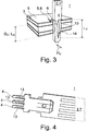
- Fig. 3 shows a sectional view of the electrical heating device 1 according to the invention.
- the at least one contact pin 4 has a radially protruding press protrusion 13.
- the press protrusion 13 deforms elastically at least area by area in the at least one contact bushing 4 and thus mounts the at least one contact pin 4 in the at least one contact bushing 6 by means of a radially acting pressing force.
- the press protrusion 13 extends axially on the at least one contact pin 4 across a length L V , which is longer than the length B L of the at least one contact bushing 6 and the thickness D P of the control board 3.
- the press protrusion 13 further has a ramp area 14, which increases steadily axially from zero to a height H V of the press protrusion 13.
- the radially acting pressing force in response to establishing the electroconductive contact between the at least one contact pin 4 and the at least one contact bushing 6 can thus increase steadily and the electroconductive contact can be established and released more easily.
- the construction of the heating device 1 shown herein corresponds to the heating device 1 shown in Fig. 1 .
- Fig. 4 shows a partial view of the heating element 2.
- the heating element 2 has three contact pins 4, which can be mounted in the control board 3 by means of the contact arrangement 4, as is shown in Fig. 2 .
- the required space for establishing the electroconductive contact between the contact pin 4 and the contact bushing 6 on the control board 3 and also in the heating device 1 can be reduced in the heating device 1 according to the invention.
- the heating device 1 according to the invention can thus in particular be constructed more compactly.
Landscapes
- Engineering & Computer Science (AREA)
- Manufacturing & Machinery (AREA)
- Microelectronics & Electronic Packaging (AREA)
- Physics & Mathematics (AREA)
- Thermal Sciences (AREA)
- Chemical & Material Sciences (AREA)
- Combustion & Propulsion (AREA)
- Mechanical Engineering (AREA)
- General Engineering & Computer Science (AREA)
- Air-Conditioning For Vehicles (AREA)
- Resistance Heating (AREA)
Priority Applications (3)
| Application Number | Priority Date | Filing Date | Title |
|---|---|---|---|
| EP18162576.5A EP3544121B1 (fr) | 2018-03-19 | 2018-03-19 | Dispositif de chauffage électrique |
| CN201910136380.4A CN110290600B (zh) | 2018-03-19 | 2019-02-25 | 电加热装置 |
| US16/357,286 US20190289673A1 (en) | 2018-03-19 | 2019-03-18 | Heating device |
Applications Claiming Priority (1)
| Application Number | Priority Date | Filing Date | Title |
|---|---|---|---|
| EP18162576.5A EP3544121B1 (fr) | 2018-03-19 | 2018-03-19 | Dispositif de chauffage électrique |
Publications (2)
| Publication Number | Publication Date |
|---|---|
| EP3544121A1 true EP3544121A1 (fr) | 2019-09-25 |
| EP3544121B1 EP3544121B1 (fr) | 2022-05-04 |
Family
ID=61691780
Family Applications (1)
| Application Number | Title | Priority Date | Filing Date |
|---|---|---|---|
| EP18162576.5A Active EP3544121B1 (fr) | 2018-03-19 | 2018-03-19 | Dispositif de chauffage électrique |
Country Status (3)
| Country | Link |
|---|---|
| US (1) | US20190289673A1 (fr) |
| EP (1) | EP3544121B1 (fr) |
| CN (1) | CN110290600B (fr) |
Cited By (1)
| Publication number | Priority date | Publication date | Assignee | Title |
|---|---|---|---|---|
| EP3927125A1 (fr) * | 2020-06-18 | 2021-12-22 | Mahle International GmbH | Unité de commande et dispositif de chauffage électrique |
Families Citing this family (2)
| Publication number | Priority date | Publication date | Assignee | Title |
|---|---|---|---|---|
| DE102019216481A1 (de) * | 2019-10-25 | 2021-04-29 | Eberspächer Catem Gmbh & Co. Kg | Elektrische Heizvorrichtung |
| EP4268540A1 (fr) * | 2020-12-23 | 2023-11-01 | Watlow Electric Manufacturing Company | Circuit de bus encapsulé pour systèmes de chauffage de fluide |
Citations (5)
| Publication number | Priority date | Publication date | Assignee | Title |
|---|---|---|---|---|
| US3964813A (en) * | 1975-02-10 | 1976-06-22 | The United States Of America As Represented By The United States National Aeronautics And Space Administration | Connector |
| EP1431992A2 (fr) * | 2002-12-16 | 2004-06-23 | TRW Automotive U.S. LLC | Dispositif interrupteur électrique |
| EP2236330A1 (fr) | 2009-03-30 | 2010-10-06 | Eberspächer catem GmbH & Co. KG | Dispositif de chauffage électrique pour véhicule automobile |
| EP2615696A1 (fr) * | 2012-01-12 | 2013-07-17 | Loupot | Contact pour emmanchement en force |
| WO2016128756A1 (fr) * | 2015-02-11 | 2016-08-18 | Trw Limited | Circuit électrique destiné à être utilisé dans un système de direction assistée électrique |
Family Cites Families (22)
| Publication number | Priority date | Publication date | Assignee | Title |
|---|---|---|---|---|
| DE10008572B4 (de) * | 2000-02-24 | 2007-08-09 | Infineon Technologies Ag | Verbindungseinrichtung für Leistungshalbleitermodule |
| GB0316506D0 (en) * | 2003-07-15 | 2003-08-20 | Thermocable Flexible Elements | Heating blanket |
| US7008272B2 (en) * | 2003-10-23 | 2006-03-07 | Trw Automotive U.S. Llc | Electrical contact |
| US7119304B2 (en) * | 2004-08-26 | 2006-10-10 | Marcy Meyers | Heated hand grip |
| EP1643804B1 (fr) * | 2004-09-29 | 2007-01-03 | Leister Process Technologies | Réchauffeur d'air |
| GB2458092B (en) * | 2006-12-27 | 2011-08-17 | Raychem Electronics | Shrink sleeve |
| DE102007047422B4 (de) * | 2007-10-04 | 2024-06-20 | Robert Bosch Gmbh | Elektromagnetisches Druckventil |
| DE102008004882A1 (de) * | 2008-01-17 | 2009-07-23 | Robert Bosch Gmbh | Einpresskontakt mit einem Sockel, einem Kontaktstift und einem zweiten Stift |
| JP4458181B2 (ja) * | 2008-04-24 | 2010-04-28 | ソニー株式会社 | 電気接触子および電子機器 |
| KR20100067259A (ko) * | 2008-12-11 | 2010-06-21 | 차승희 | 전기 히터 조립체와 이를 이용한 온풍기 및 온수기 |
| DE102009047043A1 (de) * | 2009-10-19 | 2011-04-21 | Robert Bosch Gmbh | Lötfreie elektrische Verbindung |
| EP2440005B1 (fr) * | 2010-10-08 | 2015-12-23 | Eberspächer catem GmbH & Co. KG | Dispositif de chauffage électrique et son procédé de fabrication |
| DE102010049467B4 (de) * | 2010-10-27 | 2022-08-04 | Günther Heisskanaltechnik Gmbh | Elektrische Anschlusseinrichtung für ein elektrisches Heizelement einer Heißkanaldüse und Heißkanaldüse |
| KR101379550B1 (ko) * | 2011-06-20 | 2014-03-28 | 한라비스테온공조 주식회사 | 차량의 ptc 히터 제어용 pwm 회로 |
| EP2607121B2 (fr) * | 2011-12-22 | 2020-07-08 | Eberspächer catem GmbH & Co. KG | Dispositif de chauffage électrique, en particulier pour un véhicule automobile |
| US8900008B2 (en) * | 2012-05-25 | 2014-12-02 | International Business Machines Corporation | Universal press-fit connection for printed circuit boards |
| DE102012025156A1 (de) * | 2012-12-21 | 2014-06-26 | W.E.T. Automotive Systems Ag | Elektrische Heizeinrichtung |
| JP6234034B2 (ja) * | 2013-02-20 | 2017-11-22 | 矢崎総業株式会社 | シールドコネクタ構造 |
| CN203655540U (zh) * | 2013-12-31 | 2014-06-18 | 德阳智科电子有限公司 | 一种可调功率的风电机舱ptc加热器 |
| DE102014222597A1 (de) * | 2014-11-05 | 2016-05-12 | Mahle International Gmbh | Verfahren zum Herstellen einer Anordnung mit einem Gehäuseteil und wenigstens zwei Leiterbahnen |
| RS60726B1 (sr) * | 2015-03-26 | 2020-09-30 | Pyrotek High Temperature Ind Products Inc | Čepna motka sa grejanjem |
| KR101913121B1 (ko) * | 2016-01-28 | 2018-10-31 | 자화전자(주) | 독립제어 피티씨히터 및 장치 |
-
2018
- 2018-03-19 EP EP18162576.5A patent/EP3544121B1/fr active Active
-
2019
- 2019-02-25 CN CN201910136380.4A patent/CN110290600B/zh not_active Expired - Fee Related
- 2019-03-18 US US16/357,286 patent/US20190289673A1/en not_active Abandoned
Patent Citations (5)
| Publication number | Priority date | Publication date | Assignee | Title |
|---|---|---|---|---|
| US3964813A (en) * | 1975-02-10 | 1976-06-22 | The United States Of America As Represented By The United States National Aeronautics And Space Administration | Connector |
| EP1431992A2 (fr) * | 2002-12-16 | 2004-06-23 | TRW Automotive U.S. LLC | Dispositif interrupteur électrique |
| EP2236330A1 (fr) | 2009-03-30 | 2010-10-06 | Eberspächer catem GmbH & Co. KG | Dispositif de chauffage électrique pour véhicule automobile |
| EP2615696A1 (fr) * | 2012-01-12 | 2013-07-17 | Loupot | Contact pour emmanchement en force |
| WO2016128756A1 (fr) * | 2015-02-11 | 2016-08-18 | Trw Limited | Circuit électrique destiné à être utilisé dans un système de direction assistée électrique |
Non-Patent Citations (1)
| Title |
|---|
| EBERSPÄCHER UK: "HV coolant heater technical sales notes generation 3", 31 October 2017 (2017-10-31), pages 1 - 2, XP055507365, Retrieved from the Internet <URL:https://www.eberspacher.com/fileadmin/data/countrysites/EB_UK/pdf_files/info_pdf_ebuk/electric_pdf_ebuk/hv_gen3_coolant_heater_ebuk_jn1108.pdf> [retrieved on 20180917] * |
Cited By (1)
| Publication number | Priority date | Publication date | Assignee | Title |
|---|---|---|---|---|
| EP3927125A1 (fr) * | 2020-06-18 | 2021-12-22 | Mahle International GmbH | Unité de commande et dispositif de chauffage électrique |
Also Published As
| Publication number | Publication date |
|---|---|
| EP3544121B1 (fr) | 2022-05-04 |
| US20190289673A1 (en) | 2019-09-19 |
| CN110290600B (zh) | 2022-09-02 |
| CN110290600A (zh) | 2019-09-27 |
Similar Documents
| Publication | Publication Date | Title |
|---|---|---|
| EP3544121B1 (fr) | Dispositif de chauffage électrique | |
| US8120216B2 (en) | Electric motor and electric pump unit with busbars integrally formed with driving circuit connecting terminals | |
| US7651334B2 (en) | Coaxial electrical connector | |
| EP2088840B1 (fr) | Montage de composant électronique | |
| WO2008105980A1 (fr) | Fixation de composants passifs entre des couches d'une carte à circuit imprimé | |
| US3013188A (en) | Mechanically integrated circuit board and a method of making same by die forms | |
| EP4494249B1 (fr) | Moteur électrique | |
| CN114402702A (zh) | 包括电路板和功率模块的功率电子组件、用于制造功率电子组件的方法、包括功率电子组件的机动车 | |
| CN1541047B (zh) | 高电流输出引脚 | |
| JP2013236015A (ja) | パワーモジュール、パワーモジュールにおける接続端子の取付構造および接続端子 | |
| CN111225513B (zh) | 用于连接功率电子构造元件和印刷电路板的方法和套筒 | |
| US3519982A (en) | Method and means of forming electrical connections with conductors | |
| US6259184B1 (en) | Load shifting device | |
| CN110301166B (zh) | 电子器件模块和用于制造电子器件模块的方法 | |
| US3292131A (en) | Device for interconnection of electrical apparatus | |
| CN107535067B (zh) | 优选用于功率电子器件的接触装置 | |
| DE102015109845A1 (de) | Kontaktierungseinheit für Wicklungen eines Stators eines Elektromotors mit einer Leistungsplatine | |
| JP2001068800A (ja) | 電子回路 | |
| CN111771429A (zh) | 压入配合连接结构 | |
| CN117546395A (zh) | 用于执行器的电动机 | |
| CN216390688U (zh) | 油泵电机及其电机连接器组件 | |
| CN114630522A (zh) | 包括壳体、电路以及壳体和电路之间的导电连接的装置 | |
| CN112292914A (zh) | 印刷电路板用于变速器控制的用途 | |
| CN222785825U (zh) | 一种外转子电机的定子及其应用的外转子电机 | |
| JP2012019071A (ja) | プリント配線板 |
Legal Events
| Date | Code | Title | Description |
|---|---|---|---|
| PUAI | Public reference made under article 153(3) epc to a published international application that has entered the european phase |
Free format text: ORIGINAL CODE: 0009012 |
|
| STAA | Information on the status of an ep patent application or granted ep patent |
Free format text: STATUS: THE APPLICATION HAS BEEN PUBLISHED |
|
| AK | Designated contracting states |
Kind code of ref document: A1 Designated state(s): AL AT BE BG CH CY CZ DE DK EE ES FI FR GB GR HR HU IE IS IT LI LT LU LV MC MK MT NL NO PL PT RO RS SE SI SK SM TR |
|
| AX | Request for extension of the european patent |
Extension state: BA ME |
|
| STAA | Information on the status of an ep patent application or granted ep patent |
Free format text: STATUS: REQUEST FOR EXAMINATION WAS MADE |
|
| 17P | Request for examination filed |
Effective date: 20191205 |
|
| RBV | Designated contracting states (corrected) |
Designated state(s): AL AT BE BG CH CY CZ DE DK EE ES FI FR GB GR HR HU IE IS IT LI LT LU LV MC MK MT NL NO PL PT RO RS SE SI SK SM TR |
|
| STAA | Information on the status of an ep patent application or granted ep patent |
Free format text: STATUS: EXAMINATION IS IN PROGRESS |
|
| 17Q | First examination report despatched |
Effective date: 20201104 |
|
| GRAP | Despatch of communication of intention to grant a patent |
Free format text: ORIGINAL CODE: EPIDOSNIGR1 |
|
| STAA | Information on the status of an ep patent application or granted ep patent |
Free format text: STATUS: GRANT OF PATENT IS INTENDED |
|
| RIC1 | Information provided on ipc code assigned before grant |
Ipc: F24H 9/18 20060101ALN20211118BHEP Ipc: H05K 3/40 20060101ALN20211118BHEP Ipc: H01R 12/58 20110101AFI20211118BHEP |
|
| INTG | Intention to grant announced |
Effective date: 20211202 |
|
| GRAS | Grant fee paid |
Free format text: ORIGINAL CODE: EPIDOSNIGR3 |
|
| GRAA | (expected) grant |
Free format text: ORIGINAL CODE: 0009210 |
|
| STAA | Information on the status of an ep patent application or granted ep patent |
Free format text: STATUS: THE PATENT HAS BEEN GRANTED |
|
| AK | Designated contracting states |
Kind code of ref document: B1 Designated state(s): AL AT BE BG CH CY CZ DE DK EE ES FI FR GB GR HR HU IE IS IT LI LT LU LV MC MK MT NL NO PL PT RO RS SE SI SK SM TR |
|
| REG | Reference to a national code |
Ref country code: GB Ref legal event code: FG4D |
|
| REG | Reference to a national code |
Ref country code: CH Ref legal event code: EP |
|
| REG | Reference to a national code |
Ref country code: AT Ref legal event code: REF Ref document number: 1490121 Country of ref document: AT Kind code of ref document: T Effective date: 20220515 |
|
| REG | Reference to a national code |
Ref country code: IE Ref legal event code: FG4D Ref country code: DE Ref legal event code: R096 Ref document number: 602018034766 Country of ref document: DE |
|
| REG | Reference to a national code |
Ref country code: LT Ref legal event code: MG9D |
|
| REG | Reference to a national code |
Ref country code: NL Ref legal event code: MP Effective date: 20220504 |
|
| REG | Reference to a national code |
Ref country code: AT Ref legal event code: MK05 Ref document number: 1490121 Country of ref document: AT Kind code of ref document: T Effective date: 20220504 |
|
| PG25 | Lapsed in a contracting state [announced via postgrant information from national office to epo] |
Ref country code: SE Free format text: LAPSE BECAUSE OF FAILURE TO SUBMIT A TRANSLATION OF THE DESCRIPTION OR TO PAY THE FEE WITHIN THE PRESCRIBED TIME-LIMIT Effective date: 20220504 Ref country code: PT Free format text: LAPSE BECAUSE OF FAILURE TO SUBMIT A TRANSLATION OF THE DESCRIPTION OR TO PAY THE FEE WITHIN THE PRESCRIBED TIME-LIMIT Effective date: 20220905 Ref country code: NO Free format text: LAPSE BECAUSE OF FAILURE TO SUBMIT A TRANSLATION OF THE DESCRIPTION OR TO PAY THE FEE WITHIN THE PRESCRIBED TIME-LIMIT Effective date: 20220804 Ref country code: NL Free format text: LAPSE BECAUSE OF FAILURE TO SUBMIT A TRANSLATION OF THE DESCRIPTION OR TO PAY THE FEE WITHIN THE PRESCRIBED TIME-LIMIT Effective date: 20220504 Ref country code: LT Free format text: LAPSE BECAUSE OF FAILURE TO SUBMIT A TRANSLATION OF THE DESCRIPTION OR TO PAY THE FEE WITHIN THE PRESCRIBED TIME-LIMIT Effective date: 20220504 Ref country code: HR Free format text: LAPSE BECAUSE OF FAILURE TO SUBMIT A TRANSLATION OF THE DESCRIPTION OR TO PAY THE FEE WITHIN THE PRESCRIBED TIME-LIMIT Effective date: 20220504 Ref country code: GR Free format text: LAPSE BECAUSE OF FAILURE TO SUBMIT A TRANSLATION OF THE DESCRIPTION OR TO PAY THE FEE WITHIN THE PRESCRIBED TIME-LIMIT Effective date: 20220805 Ref country code: FI Free format text: LAPSE BECAUSE OF FAILURE TO SUBMIT A TRANSLATION OF THE DESCRIPTION OR TO PAY THE FEE WITHIN THE PRESCRIBED TIME-LIMIT Effective date: 20220504 Ref country code: ES Free format text: LAPSE BECAUSE OF FAILURE TO SUBMIT A TRANSLATION OF THE DESCRIPTION OR TO PAY THE FEE WITHIN THE PRESCRIBED TIME-LIMIT Effective date: 20220504 Ref country code: BG Free format text: LAPSE BECAUSE OF FAILURE TO SUBMIT A TRANSLATION OF THE DESCRIPTION OR TO PAY THE FEE WITHIN THE PRESCRIBED TIME-LIMIT Effective date: 20220804 Ref country code: AT Free format text: LAPSE BECAUSE OF FAILURE TO SUBMIT A TRANSLATION OF THE DESCRIPTION OR TO PAY THE FEE WITHIN THE PRESCRIBED TIME-LIMIT Effective date: 20220504 |
|
| PG25 | Lapsed in a contracting state [announced via postgrant information from national office to epo] |
Ref country code: RS Free format text: LAPSE BECAUSE OF FAILURE TO SUBMIT A TRANSLATION OF THE DESCRIPTION OR TO PAY THE FEE WITHIN THE PRESCRIBED TIME-LIMIT Effective date: 20220504 Ref country code: PL Free format text: LAPSE BECAUSE OF FAILURE TO SUBMIT A TRANSLATION OF THE DESCRIPTION OR TO PAY THE FEE WITHIN THE PRESCRIBED TIME-LIMIT Effective date: 20220504 Ref country code: LV Free format text: LAPSE BECAUSE OF FAILURE TO SUBMIT A TRANSLATION OF THE DESCRIPTION OR TO PAY THE FEE WITHIN THE PRESCRIBED TIME-LIMIT Effective date: 20220504 Ref country code: IS Free format text: LAPSE BECAUSE OF FAILURE TO SUBMIT A TRANSLATION OF THE DESCRIPTION OR TO PAY THE FEE WITHIN THE PRESCRIBED TIME-LIMIT Effective date: 20220904 |
|
| PG25 | Lapsed in a contracting state [announced via postgrant information from national office to epo] |
Ref country code: SM Free format text: LAPSE BECAUSE OF FAILURE TO SUBMIT A TRANSLATION OF THE DESCRIPTION OR TO PAY THE FEE WITHIN THE PRESCRIBED TIME-LIMIT Effective date: 20220504 Ref country code: SK Free format text: LAPSE BECAUSE OF FAILURE TO SUBMIT A TRANSLATION OF THE DESCRIPTION OR TO PAY THE FEE WITHIN THE PRESCRIBED TIME-LIMIT Effective date: 20220504 Ref country code: RO Free format text: LAPSE BECAUSE OF FAILURE TO SUBMIT A TRANSLATION OF THE DESCRIPTION OR TO PAY THE FEE WITHIN THE PRESCRIBED TIME-LIMIT Effective date: 20220504 Ref country code: EE Free format text: LAPSE BECAUSE OF FAILURE TO SUBMIT A TRANSLATION OF THE DESCRIPTION OR TO PAY THE FEE WITHIN THE PRESCRIBED TIME-LIMIT Effective date: 20220504 Ref country code: DK Free format text: LAPSE BECAUSE OF FAILURE TO SUBMIT A TRANSLATION OF THE DESCRIPTION OR TO PAY THE FEE WITHIN THE PRESCRIBED TIME-LIMIT Effective date: 20220504 Ref country code: CZ Free format text: LAPSE BECAUSE OF FAILURE TO SUBMIT A TRANSLATION OF THE DESCRIPTION OR TO PAY THE FEE WITHIN THE PRESCRIBED TIME-LIMIT Effective date: 20220504 |
|
| REG | Reference to a national code |
Ref country code: DE Ref legal event code: R097 Ref document number: 602018034766 Country of ref document: DE |
|
| PLBE | No opposition filed within time limit |
Free format text: ORIGINAL CODE: 0009261 |
|
| STAA | Information on the status of an ep patent application or granted ep patent |
Free format text: STATUS: NO OPPOSITION FILED WITHIN TIME LIMIT |
|
| PG25 | Lapsed in a contracting state [announced via postgrant information from national office to epo] |
Ref country code: AL Free format text: LAPSE BECAUSE OF FAILURE TO SUBMIT A TRANSLATION OF THE DESCRIPTION OR TO PAY THE FEE WITHIN THE PRESCRIBED TIME-LIMIT Effective date: 20220504 |
|
| 26N | No opposition filed |
Effective date: 20230207 |
|
| PG25 | Lapsed in a contracting state [announced via postgrant information from national office to epo] |
Ref country code: SI Free format text: LAPSE BECAUSE OF FAILURE TO SUBMIT A TRANSLATION OF THE DESCRIPTION OR TO PAY THE FEE WITHIN THE PRESCRIBED TIME-LIMIT Effective date: 20220504 |
|
| PG25 | Lapsed in a contracting state [announced via postgrant information from national office to epo] |
Ref country code: MC Free format text: LAPSE BECAUSE OF FAILURE TO SUBMIT A TRANSLATION OF THE DESCRIPTION OR TO PAY THE FEE WITHIN THE PRESCRIBED TIME-LIMIT Effective date: 20220504 |
|
| REG | Reference to a national code |
Ref country code: CH Ref legal event code: PL |
|
| GBPC | Gb: european patent ceased through non-payment of renewal fee |
Effective date: 20230319 |
|
| REG | Reference to a national code |
Ref country code: BE Ref legal event code: MM Effective date: 20230331 |
|
| PG25 | Lapsed in a contracting state [announced via postgrant information from national office to epo] |
Ref country code: LU Free format text: LAPSE BECAUSE OF NON-PAYMENT OF DUE FEES Effective date: 20230319 |
|
| REG | Reference to a national code |
Ref country code: IE Ref legal event code: MM4A |
|
| PG25 | Lapsed in a contracting state [announced via postgrant information from national office to epo] |
Ref country code: GB Free format text: LAPSE BECAUSE OF NON-PAYMENT OF DUE FEES Effective date: 20230319 |
|
| PG25 | Lapsed in a contracting state [announced via postgrant information from national office to epo] |
Ref country code: LI Free format text: LAPSE BECAUSE OF NON-PAYMENT OF DUE FEES Effective date: 20230331 Ref country code: IT Free format text: LAPSE BECAUSE OF FAILURE TO SUBMIT A TRANSLATION OF THE DESCRIPTION OR TO PAY THE FEE WITHIN THE PRESCRIBED TIME-LIMIT Effective date: 20220504 Ref country code: IE Free format text: LAPSE BECAUSE OF NON-PAYMENT OF DUE FEES Effective date: 20230319 Ref country code: GB Free format text: LAPSE BECAUSE OF NON-PAYMENT OF DUE FEES Effective date: 20230319 Ref country code: FR Free format text: LAPSE BECAUSE OF NON-PAYMENT OF DUE FEES Effective date: 20230331 Ref country code: CH Free format text: LAPSE BECAUSE OF NON-PAYMENT OF DUE FEES Effective date: 20230331 |
|
| PG25 | Lapsed in a contracting state [announced via postgrant information from national office to epo] |
Ref country code: BE Free format text: LAPSE BECAUSE OF NON-PAYMENT OF DUE FEES Effective date: 20230331 |
|
| P01 | Opt-out of the competence of the unified patent court (upc) registered |
Effective date: 20240527 |
|
| PG25 | Lapsed in a contracting state [announced via postgrant information from national office to epo] |
Ref country code: BG Free format text: LAPSE BECAUSE OF FAILURE TO SUBMIT A TRANSLATION OF THE DESCRIPTION OR TO PAY THE FEE WITHIN THE PRESCRIBED TIME-LIMIT Effective date: 20220504 |
|
| PG25 | Lapsed in a contracting state [announced via postgrant information from national office to epo] |
Ref country code: BG Free format text: LAPSE BECAUSE OF FAILURE TO SUBMIT A TRANSLATION OF THE DESCRIPTION OR TO PAY THE FEE WITHIN THE PRESCRIBED TIME-LIMIT Effective date: 20220504 |
|
| PG25 | Lapsed in a contracting state [announced via postgrant information from national office to epo] |
Ref country code: CY Free format text: LAPSE BECAUSE OF FAILURE TO SUBMIT A TRANSLATION OF THE DESCRIPTION OR TO PAY THE FEE WITHIN THE PRESCRIBED TIME-LIMIT; INVALID AB INITIO Effective date: 20180319 |
|
| PG25 | Lapsed in a contracting state [announced via postgrant information from national office to epo] |
Ref country code: HU Free format text: LAPSE BECAUSE OF FAILURE TO SUBMIT A TRANSLATION OF THE DESCRIPTION OR TO PAY THE FEE WITHIN THE PRESCRIBED TIME-LIMIT; INVALID AB INITIO Effective date: 20180319 |
|
| PG25 | Lapsed in a contracting state [announced via postgrant information from national office to epo] |
Ref country code: TR Free format text: LAPSE BECAUSE OF FAILURE TO SUBMIT A TRANSLATION OF THE DESCRIPTION OR TO PAY THE FEE WITHIN THE PRESCRIBED TIME-LIMIT Effective date: 20220504 |
|
| PGFP | Annual fee paid to national office [announced via postgrant information from national office to epo] |
Ref country code: DE Payment date: 20260319 Year of fee payment: 9 |