EP3544176A1 - Module de refroidissement pour une unité photovoltaïque - Google Patents
Module de refroidissement pour une unité photovoltaïque Download PDFInfo
- Publication number
- EP3544176A1 EP3544176A1 EP19171545.7A EP19171545A EP3544176A1 EP 3544176 A1 EP3544176 A1 EP 3544176A1 EP 19171545 A EP19171545 A EP 19171545A EP 3544176 A1 EP3544176 A1 EP 3544176A1
- Authority
- EP
- European Patent Office
- Prior art keywords
- cooling module
- fluid
- enclosure
- core
- enclosures
- Prior art date
- Legal status (The legal status is an assumption and is not a legal conclusion. Google has not performed a legal analysis and makes no representation as to the accuracy of the status listed.)
- Granted
Links
Images


Classifications
-
- H—ELECTRICITY
- H02—GENERATION; CONVERSION OR DISTRIBUTION OF ELECTRIC POWER
- H02S—GENERATION OF ELECTRIC POWER BY CONVERSION OF INFRARED RADIATION, VISIBLE LIGHT OR ULTRAVIOLET LIGHT, e.g. USING PHOTOVOLTAIC [PV] MODULES
- H02S40/00—Components or accessories in combination with PV modules, not provided for in groups H02S10/00 - H02S30/00
- H02S40/40—Thermal components
- H02S40/42—Cooling means
- H02S40/425—Cooling means using a gaseous or a liquid coolant, e.g. air flow ventilation, water circulation
-
- H—ELECTRICITY
- H02—GENERATION; CONVERSION OR DISTRIBUTION OF ELECTRIC POWER
- H02S—GENERATION OF ELECTRIC POWER BY CONVERSION OF INFRARED RADIATION, VISIBLE LIGHT OR ULTRAVIOLET LIGHT, e.g. USING PHOTOVOLTAIC [PV] MODULES
- H02S30/00—Structural details of PV modules other than those related to light conversion
-
- H—ELECTRICITY
- H02—GENERATION; CONVERSION OR DISTRIBUTION OF ELECTRIC POWER
- H02S—GENERATION OF ELECTRIC POWER BY CONVERSION OF INFRARED RADIATION, VISIBLE LIGHT OR ULTRAVIOLET LIGHT, e.g. USING PHOTOVOLTAIC [PV] MODULES
- H02S40/00—Components or accessories in combination with PV modules, not provided for in groups H02S10/00 - H02S30/00
- H02S40/40—Thermal components
- H02S40/44—Means to utilise heat energy, e.g. hybrid systems producing warm water and electricity at the same time
-
- D—TEXTILES; PAPER
- D06—TREATMENT OF TEXTILES OR THE LIKE; LAUNDERING; FLEXIBLE MATERIALS NOT OTHERWISE PROVIDED FOR
- D06F—LAUNDERING, DRYING, IRONING, PRESSING OR FOLDING TEXTILE ARTICLES
- D06F2103/00—Parameters monitored or detected for the control of domestic laundry washing machines, washer-dryers or laundry dryers
- D06F2103/28—Air properties
- D06F2103/36—Flow or velocity
-
- D—TEXTILES; PAPER
- D06—TREATMENT OF TEXTILES OR THE LIKE; LAUNDERING; FLEXIBLE MATERIALS NOT OTHERWISE PROVIDED FOR
- D06F—LAUNDERING, DRYING, IRONING, PRESSING OR FOLDING TEXTILE ARTICLES
- D06F2105/00—Systems or parameters controlled or affected by the control systems of washing machines, washer-dryers or laundry dryers
- D06F2105/16—Air properties
- D06F2105/24—Flow or velocity
-
- Y—GENERAL TAGGING OF NEW TECHNOLOGICAL DEVELOPMENTS; GENERAL TAGGING OF CROSS-SECTIONAL TECHNOLOGIES SPANNING OVER SEVERAL SECTIONS OF THE IPC; TECHNICAL SUBJECTS COVERED BY FORMER USPC CROSS-REFERENCE ART COLLECTIONS [XRACs] AND DIGESTS
- Y02—TECHNOLOGIES OR APPLICATIONS FOR MITIGATION OR ADAPTATION AGAINST CLIMATE CHANGE
- Y02E—REDUCTION OF GREENHOUSE GAS [GHG] EMISSIONS, RELATED TO ENERGY GENERATION, TRANSMISSION OR DISTRIBUTION
- Y02E10/00—Energy generation through renewable energy sources
- Y02E10/50—Photovoltaic [PV] energy
-
- Y—GENERAL TAGGING OF NEW TECHNOLOGICAL DEVELOPMENTS; GENERAL TAGGING OF CROSS-SECTIONAL TECHNOLOGIES SPANNING OVER SEVERAL SECTIONS OF THE IPC; TECHNICAL SUBJECTS COVERED BY FORMER USPC CROSS-REFERENCE ART COLLECTIONS [XRACs] AND DIGESTS
- Y02—TECHNOLOGIES OR APPLICATIONS FOR MITIGATION OR ADAPTATION AGAINST CLIMATE CHANGE
- Y02E—REDUCTION OF GREENHOUSE GAS [GHG] EMISSIONS, RELATED TO ENERGY GENERATION, TRANSMISSION OR DISTRIBUTION
- Y02E10/00—Energy generation through renewable energy sources
- Y02E10/60—Thermal-PV hybrids
Definitions
- the invention relates to a cooling module for a photovoltaic unit.
- cooling modules for photovoltaic units are known to protect the latter from overheating and to improve efficiency. Occasionally, the dissipated during cooling of the photovoltaic units heat is dissipated by a fluid and used.
- the invention is based on the object of specifying an improved cooling module for a photovoltaic unit.
- a cooling module is provided for a photovoltaic unit.
- the cooling module has a core formed as a plate-shaped 3-D textile, which is formed as a spacer fabric, which can be traversed by a fluid.
- the spacer fabric has a plurality of pile threads, whereby the plate-shaped core and thus the entire cooling module has a high resistance to forces acting normal to the plate direction.
- An embodiment of the cooling module provides that at least one surface of the core is provided with a coating which is fluid-tight, in particular water-impermeable and weather-resistant.
- a coating which is fluid-tight, in particular water-impermeable and weather-resistant.
- both surfaces of the core provided with the coating.
- a good tightness can be achieved with comparatively little effort.
- the surface of the core facing away from the photovoltaic unit is provided with the coating, and the surface of the core facing the photovoltaic unit is connected to the photovoltaic unit in a fluid-tight manner, in particular watertight.
- a coating is formed from silicone and has a single-layer or a multilayer structure.
- a first, ie inner, silicone layer produces a good bond to the spacer fabric, the second, outer silicone layer closes openings of the first silicone layer, so that a particularly reliable tightness can be achieved by the multilayer structure of the silicone coating.
- a further embodiment of the cooling module provides that edge surfaces of the core are each provided with a border, which are fluid-impermeable. As a result, the closed element can be produced in a simple manner.
- a number of the enclosures preferably each have a U-shaped cross section.
- This U-shaped cross section in each case has a border parallel to the edge and in each case two parallel flanges whose inner spacing corresponds with the thickness of the core with the one-sided or double-sided coating.
- inner surfaces of the two parallel flanges are at least partially connected in a fluid-tight manner to outer surfaces of the two-sided coatings. This is a simple way to effect a reliable tightness of the closed element.
- enclosures it is particularly preferable for enclosures to be arranged on two opposite edge surfaces of the core in such a way that the web of the skirt is spaced apart from the corresponding lateral edge surface in such a way that of the lateral edge surface and the corresponding enclosure a cavity is formed.
- This cavity can be traversed by the fluid parallel to the lateral edge surface.
- a particularly effective channel can be formed, which can be used for a transverse distribution of the fluid before and / or after the core has been longitudinally flowed through by the fluid.
- the flow in the transverse distribution of the fluid parallel to the lateral edge surface in said channel allows the flow through the formed as a spacer knit core is very homogeneous, ie very uniformly with substantially constant volume flow.
- the cooling module thus allows a uniform and thus very effective removal of heat from the photovoltaic unit. As a result, the cooling module is relatively thin auslagbar and comparatively inexpensive to produce.
- a number of inlets are arranged on a first enclosure and a number of processes are arranged on the second enclosure opposite the first enclosure.
- two inlets and outlets are each arranged normal to the cooling module and designed as tubes for connecting a fluid line.
- the inlets and outlets are each provided with an external thread.
- a further development provides that at two other, also opposite edge surfaces arranged enclosures are arranged such that in each case the web rests against the corresponding lateral edge surface which lies in the longitudinal flow direction.
- the fluid can not flow parallel to this lateral edge surface between the lateral edge surface and the corresponding skirt, as a result of which the fluid can flow exclusively through the core in the longitudinal flow direction. This allows a particularly homogeneous flow in the longitudinal direction in a simple manner.
- a number of the enclosures are preferably formed of aluminum, whereby the cooling module with a low weight and high accuracy can be produced.
- corner joints of two adjacent enclosures are in each case designed to be watertight, for example adhesively bonded or connected by means of a fluid-tight corner element.
- the closed element is comprehensively sealable.
- an enclosure with an end-face corner element or with two end-side corner elements may be integrally formed.
- a particular embodiment of the cooling module provides that a recess penetrating the core and the coatings is provided, which is designed such that the fluid can not escape.
- This fluid-tight passage through the core, which is arranged between the opposing coatings, serves to pass through electrical lines of the associated photovoltaic unit.
- This passage is preferably arranged next to one of the enclosures, which has inlets or outlets.
- this makes it possible to cool the photovoltaic unit over the entire area and completely, and thus evenly.
- a photovoltaic unit in the area of a junction box can not only be formed, but also efficiently cooled.
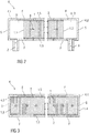
- FIG. 1 shows a schematic plan view of an embodiment of a cooling module according to the invention K.
- the cooling module K comprises a plate-shaped core 1, the 3-D textile is formed as a spacer.
- the core 1 has a multiplicity of pile threads and is provided on both sides, ie on both of its parallel surfaces 1.S, with a water-impermeable two-layer coating 2 made of silicone.
- the plate-shaped core 1 has a first edge surface 1.1, a second edge surface 1.2, a third edge surface 1.3 and a fourth edge surface 1.4, on each of which correspondingly a first enclosure 4.1, a second Mount 4.2, a third enclosure 4.3 and a fourth enclosure 4.4 is arranged.
- All enclosures 4.1, 4.2, 4.3, 4.4 each have a U-shaped cross-section shown in more detail in the following figures, each with a not shown edge-parallel web S and two here also not shown parallel flanges F and are made of aluminum.
- the enclosures 4.1, 4.2, 4.3, 4.4 are themselves waterproof and connected to the coating 2 watertight.
- the corner joints of adjacent enclosures 4.1, 4.2, 4.3, 4.4, which are formed by a miter, are not only mechanically strong but also watertight.
- first and second edge surfaces 1.1, 1.2 are corresponding first and second enclosures 4.1, 4.2 arranged such that each of the not designated here web S is spaced from the corresponding lateral edge surface 1.1, 1.2 such that a cavity H is formed, which can be flowed through by a fluid 3 substantially parallel to the lateral edge surface 1.1, 1.2.
- the flow direction of the fluid 3 is represented by arrows, wherein the arrow length is shown schematically corresponding to the size of the volume flow.
- third and fourth enclosures 4.3, 4.4 are third and fourth enclosures 4.3, 4.4 arranged such that in each case the web S, not shown here rests against the corresponding lateral edge surface 1.3, 1.4.
- two sleeve-shaped inlets Z are arranged normal to the plane of the plate and at the first enclosure 4.1 opposite second enclosure 4.2 are normal to the plate plane two sleeve-shaped processes A arranged.
- the fluid 3 flowing in via the two inlets Z into the cavity H shown above is initially distributed essentially transversely in the same and flows very uniformly parallel to the third and the fourth edge surface 1.3, 1.4 through the core 1 This longitudinal flow direction, the fluid flows exclusively through the core 1, whereby the particularly homogeneous flow is made possible in a simple manner.
- FIG. 2 shows you one FIG. 1 corresponding schematic cross-section of the cooling module K.
- the illustrated on the left first enclosure 4.1 and the second enclosure 4.2 shown on the right each have the aforementioned U-shaped cross section, each with a border-parallel web S and two parallel flanges F on.
- the inner surfaces of the flanges F are waterproofly connected respectively to the corresponding outer surface of the coating 2 disposed on each of the surfaces 1.S.
- the web S of each enclosure 4.1 and 4.2 is spaced from the respective corresponding lateral edge surface 1.1, 1.2, so that the aforementioned cavity H is formed, which can be traversed by the fluid 3 substantially parallel to the lateral edge surface 1.1, 1.2 before or after the fluid 3 flows through the core 1 in the direction of the arrow from left to right.
- FIG. 3 shows one to the FIGS. 1 and 2 corresponding schematic longitudinal section of the cooling module K.
- the third enclosure 4.3 shown on the left and the fourth enclosure 4.4 shown on the right also each have the aforementioned U-shaped cross section, each with a border-parallel web S and two parallel flanges F on.
- the inner surfaces of these flanges F are also waterproof respectively connected to the corresponding outer surface of the coating 2, which is disposed on each of the surfaces 1.S.
- the web S of each enclosure 4.3 and 4.4 is in direct contact with the respectively corresponding lateral edge surface 1.3, 1.4, so that the fluid 3 in the region of the core 1 can flow essentially parallel to the lateral edge surface 1.3, 1.4; this is shown schematically by five arrow ends.
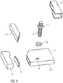
- FIG. 4 shows a section of a perspective exploded view of a second embodiment of the cooling module according to the invention K. It is shown schematically how to connect the second enclosure 4.2 with the third enclosure 4.3 and how the second enclosure 4.2 and the third enclosure 4.3 are formed.
- the second enclosure 4.2 and the third enclosure 4.3 have a miter in the connection area.
- the width of the flange F of the second enclosure 4.2 is greater than that of the third enclosure 4.3 and has a bore 5, to which the outlet A, which is designed as a threaded tube, can be connected.
- a first nut 6 is attached to the top of the flange F of the second enclosure 4.2 watertight; then designed as a threaded pipe sequence A is screwed watertight in this first nut 6.
- a second nut 7 is used for locking and thus for fixing the drain A in the first nut 6.
- the first nut 6 is disposed below the flange F and the second nut 7 above the flange F and screwed-A screwed against each other; In this case, the sequence A is waterproof connected to the second enclosure 4.2.
- a plug 8 By means of a plug 8 is or an end opening of the second enclosure 4.2 is sealed waterproof, for example, the plug 8 is glued waterproof.
- a corner shoe 9 which is shown in two views for better understanding, the corner region formed from the third enclosure 4.3 attached to the second enclosure 4.2, including the plug 8, is covered.
- the inner width of the corner shoe 9 is slightly larger than the outer width of the second enclosure 4.2 and the third enclosure 4.3.
- the core 1, not shown here, with the coatings 2, not shown here, is designed as described in the aforementioned figures and is enclosed watertight by the casings 4.1 to 4.4.
- FIG. 5 shows a schematic sectional view of a section of a cooling module K according to the invention with a recess 1.A, which serves to carry electrical cables of a photovoltaic unit.
- the recess 1.A in the core 1 is formed such that the fluid 3 can not escape.
- an upper passage element 10 is connected watertight to a lower passage element 11.
- the upper passage member 10 is also waterproof connected to the upper coating 2.
- the lower passage member 11 is waterproofly connected to the lower coating 2.
- the upper passage element 10 which in FIG. 6 is shown in perspective, a plate-shaped upper flange 10.1, which is adhesively bonded to the underside of the upper surface of the upper coating 2.
- the upper passage element 10 also has a collar 10.2, in which a corresponding collar of the lower passage element 11 can be inserted and adhesively bonded in a water-tight manner.
- the lower passage member 11 has a plate-shaped flange portion, which is glued on the upper side with the underside of the lower coating 2.
- the cooling module K preferably has a length of 1000 mm to 2000 mm, more preferably of 1500 mm.
- the preferred width is 600 mm to 1000 mm, particularly preferably 800 mm.
- the preferred thickness is 6 mm to 10 mm, more preferably 8 mm.
- the diameters of the inlets Z and the outlets A are between 3/8 inch and 1 inch.
- the cooling module K Before the cooling module K is applied to the corresponding photovoltaic unit, this is subjected to a quality inspection.
- the cooling module K is first tested without pressure with an open system and then with a closed system with a pressure of 3 bar.
Landscapes
- Photovoltaic Devices (AREA)
- Cooling Or The Like Of Electrical Apparatus (AREA)
Applications Claiming Priority (3)
| Application Number | Priority Date | Filing Date | Title |
|---|---|---|---|
| DE102015220984.9A DE102015220984A1 (de) | 2015-10-27 | 2015-10-27 | Kühlmodul für eine Photovoltaikeinheit |
| PCT/EP2016/075887 WO2017072212A1 (fr) | 2015-10-27 | 2016-10-27 | Module de refroidissment pour une unité photovoltaïque |
| EP16793791.1A EP3369170B1 (fr) | 2015-10-27 | 2016-10-27 | Module de refroidissment pour une unité photovoltaïque |
Related Parent Applications (1)
| Application Number | Title | Priority Date | Filing Date |
|---|---|---|---|
| EP16793791.1A Division EP3369170B1 (fr) | 2015-10-27 | 2016-10-27 | Module de refroidissment pour une unité photovoltaïque |
Publications (3)
| Publication Number | Publication Date |
|---|---|
| EP3544176A1 true EP3544176A1 (fr) | 2019-09-25 |
| EP3544176C0 EP3544176C0 (fr) | 2023-08-02 |
| EP3544176B1 EP3544176B1 (fr) | 2023-08-02 |
Family
ID=57256273
Family Applications (2)
| Application Number | Title | Priority Date | Filing Date |
|---|---|---|---|
| EP19171545.7A Active EP3544176B1 (fr) | 2015-10-27 | 2016-10-27 | Module de refroidissement pour une unité photovoltaïque |
| EP16793791.1A Active EP3369170B1 (fr) | 2015-10-27 | 2016-10-27 | Module de refroidissment pour une unité photovoltaïque |
Family Applications After (1)
| Application Number | Title | Priority Date | Filing Date |
|---|---|---|---|
| EP16793791.1A Active EP3369170B1 (fr) | 2015-10-27 | 2016-10-27 | Module de refroidissment pour une unité photovoltaïque |
Country Status (14)
| Country | Link |
|---|---|
| US (1) | US10461686B2 (fr) |
| EP (2) | EP3544176B1 (fr) |
| CN (2) | CN114531112A (fr) |
| DE (2) | DE202015008919U1 (fr) |
| DK (1) | DK3369170T3 (fr) |
| ES (1) | ES2733632T3 (fr) |
| HR (1) | HRP20191301T1 (fr) |
| HU (1) | HUE044607T2 (fr) |
| PL (1) | PL3369170T3 (fr) |
| PT (1) | PT3369170T (fr) |
| RS (1) | RS59105B1 (fr) |
| SI (1) | SI3369170T1 (fr) |
| TR (1) | TR201909192T4 (fr) |
| WO (1) | WO2017072212A1 (fr) |
Families Citing this family (6)
| Publication number | Priority date | Publication date | Assignee | Title |
|---|---|---|---|---|
| DE202015008919U1 (de) * | 2015-10-27 | 2016-02-22 | ITP GmbH - Gesellschaft für Intelligente Produkte | Kühlmodul für eine Photovoltaikeinheit |
| NL2024043B1 (en) * | 2019-10-18 | 2021-06-22 | Viridi Holding B V | Energy system and method, and data carrier comprising instructions therefor |
| NL2024045B1 (nl) * | 2019-10-18 | 2021-06-22 | Viridi Holding B V | Frame voor een door een vloeistof doorstroombaar 3d-textiel en samenstel van een dergelijk frame en 3d-textiel |
| NL2028343B1 (en) | 2021-05-31 | 2022-12-12 | Viridi Holding B V | Heating and/or cooling module for a photovoltaic panel |
| DE102022210763A1 (de) * | 2022-10-12 | 2024-04-18 | ITP GmbH Gesellschaft für intelligente textile Produkte | Textiler Erdwärmetauscher sowie Verfahren zur Herstellung und Verwendung eines textilen Erdwärmetauschers |
| EP4432556A1 (fr) * | 2023-03-17 | 2024-09-18 | AT Advanced Technologies GmbH | Système hybride photovoltaïque-thermique |
Citations (7)
| Publication number | Priority date | Publication date | Assignee | Title |
|---|---|---|---|---|
| US20050061311A1 (en) * | 2001-12-01 | 2005-03-24 | Christensen Hans Jorgen | Solar collector panel for heating ventilation air |
| US20070028960A1 (en) * | 2005-08-03 | 2007-02-08 | The University Of Sydney | Active cooling device |
| US20080073062A1 (en) * | 2006-09-26 | 2008-03-27 | Onscreen Technologies, Inc. | Sealed self-contained fluidic cooling device |
| US20090308433A1 (en) * | 2008-06-17 | 2009-12-17 | Waytronx, Inc. | Method and apparatus for cooling of solar power cells |
| US7956278B1 (en) * | 2007-03-15 | 2011-06-07 | Onscreen Technologies, Inc. | Solar heat transfer apparatus |
| US20110297144A1 (en) * | 2009-01-12 | 2011-12-08 | Tarakcioglu Isik | Textile based air heater solar collector |
| US20140360556A1 (en) * | 2013-06-10 | 2014-12-11 | SunEdison Energy India Private Limited | Methods and systems for temperature regulation of roof mounted and solar tracker mounted photovoltaic modules |
Family Cites Families (18)
| Publication number | Priority date | Publication date | Assignee | Title |
|---|---|---|---|---|
| US3937208A (en) * | 1975-01-20 | 1976-02-10 | Sunearth Construction Company, Inc. | Solar collector system |
| US4244353A (en) * | 1977-04-07 | 1981-01-13 | Straza George T | Solar heating shingle roof structure |
| US4413157A (en) * | 1981-03-09 | 1983-11-01 | Ames Douglas A | Hybrid photovoltaic-thermal device |
| EP1625885A1 (fr) * | 2004-08-11 | 2006-02-15 | Vlaamse Instelling Voor Technologisch Onderzoek (Vito) | Membrane avec des conduits de perméat intégrés |
| DE202004013267U1 (de) * | 2004-08-24 | 2005-02-10 | Deutsche Institute für Textil- und Faserforschung Stuttgart - Stiftung des öffentlichen Rechts | Beschichtete Abstandstextilien für Solarkollektoren |
| DE102005054367A1 (de) * | 2005-11-15 | 2007-05-16 | Durlum Leuchten | Solarkollektor |
| US20080302405A1 (en) * | 2007-06-05 | 2008-12-11 | Michael Intrieri | Supplemental solar energy collector |
| CN102422436A (zh) * | 2009-04-21 | 2012-04-18 | 优纳T&E株式会社 | 具有冷却装置的光伏模块及其冷却装置的制造方法 |
| US9103564B2 (en) | 2009-10-16 | 2015-08-11 | Soleeva Corporation | Solar energy converter and method for converting solar energy |
| US9816729B2 (en) * | 2009-11-20 | 2017-11-14 | Mark W Miles | Solar flux conversion module with supported fluid transport |
| US8559323B2 (en) * | 2010-03-10 | 2013-10-15 | Cisco Technology, Inc. | Downlink OFDMA for service sets with mixed client types |
| DE102011014383B4 (de) * | 2011-03-17 | 2013-01-03 | Entrak Energie- Und Antriebstechnik Gmbh & Co. Kg | Kleidungsstück zur Personenklimatisierung |
| KR101444982B1 (ko) * | 2011-06-20 | 2014-09-29 | 주식회사 엘지화학 | 광전지 모듈용 냉각시트, 이의 제조 방법 및 이를 포함하는 광전지 모듈 |
| CN202111137U (zh) * | 2011-07-01 | 2012-01-11 | 常州依利奥斯太阳能科技有限公司 | 太阳能光伏组件单元装置 |
| GB2500703A (en) * | 2012-03-30 | 2013-10-02 | Ibm | Cooling devices for photovoltaic modules |
| DE102013008957A1 (de) * | 2013-05-27 | 2014-11-27 | Cebrail Beyaz | PV PlusTherm |
| DE102013214470B4 (de) * | 2013-07-24 | 2017-01-26 | Bayerisches Zentrum für Angewandte Energieforschung e.V. | Photovoltaikmodul mit photovoltaischen Elementen an der Vorderseite und einer offenporigen Schicht an der Rückseite sowie Anordnung zur Stromerzeugung |
| DE202015008919U1 (de) * | 2015-10-27 | 2016-02-22 | ITP GmbH - Gesellschaft für Intelligente Produkte | Kühlmodul für eine Photovoltaikeinheit |
-
2015
- 2015-10-27 DE DE202015008919.4U patent/DE202015008919U1/de not_active Expired - Lifetime
- 2015-10-27 DE DE102015220984.9A patent/DE102015220984A1/de not_active Ceased
-
2016
- 2016-10-27 TR TR2019/09192T patent/TR201909192T4/tr unknown
- 2016-10-27 EP EP19171545.7A patent/EP3544176B1/fr active Active
- 2016-10-27 PT PT16793791T patent/PT3369170T/pt unknown
- 2016-10-27 SI SI201630283T patent/SI3369170T1/sl unknown
- 2016-10-27 DK DK16793791.1T patent/DK3369170T3/da active
- 2016-10-27 ES ES16793791T patent/ES2733632T3/es active Active
- 2016-10-27 CN CN202210269628.6A patent/CN114531112A/zh active Pending
- 2016-10-27 HU HUE16793791 patent/HUE044607T2/hu unknown
- 2016-10-27 EP EP16793791.1A patent/EP3369170B1/fr active Active
- 2016-10-27 RS RS20190751A patent/RS59105B1/sr unknown
- 2016-10-27 WO PCT/EP2016/075887 patent/WO2017072212A1/fr not_active Ceased
- 2016-10-27 HR HRP20191301TT patent/HRP20191301T1/hr unknown
- 2016-10-27 CN CN201680063006.0A patent/CN108352806B/zh active Active
- 2016-10-27 PL PL16793791T patent/PL3369170T3/pl unknown
-
2018
- 2018-04-27 US US15/965,140 patent/US10461686B2/en active Active
Patent Citations (7)
| Publication number | Priority date | Publication date | Assignee | Title |
|---|---|---|---|---|
| US20050061311A1 (en) * | 2001-12-01 | 2005-03-24 | Christensen Hans Jorgen | Solar collector panel for heating ventilation air |
| US20070028960A1 (en) * | 2005-08-03 | 2007-02-08 | The University Of Sydney | Active cooling device |
| US20080073062A1 (en) * | 2006-09-26 | 2008-03-27 | Onscreen Technologies, Inc. | Sealed self-contained fluidic cooling device |
| US7956278B1 (en) * | 2007-03-15 | 2011-06-07 | Onscreen Technologies, Inc. | Solar heat transfer apparatus |
| US20090308433A1 (en) * | 2008-06-17 | 2009-12-17 | Waytronx, Inc. | Method and apparatus for cooling of solar power cells |
| US20110297144A1 (en) * | 2009-01-12 | 2011-12-08 | Tarakcioglu Isik | Textile based air heater solar collector |
| US20140360556A1 (en) * | 2013-06-10 | 2014-12-11 | SunEdison Energy India Private Limited | Methods and systems for temperature regulation of roof mounted and solar tracker mounted photovoltaic modules |
Also Published As
| Publication number | Publication date |
|---|---|
| CN108352806B (zh) | 2022-03-25 |
| US10461686B2 (en) | 2019-10-29 |
| EP3544176C0 (fr) | 2023-08-02 |
| DE102015220984A1 (de) | 2017-04-27 |
| DK3369170T3 (da) | 2019-07-22 |
| CN108352806A (zh) | 2018-07-31 |
| HUE044607T2 (hu) | 2019-11-28 |
| ES2733632T3 (es) | 2019-12-02 |
| WO2017072212A1 (fr) | 2017-05-04 |
| CN114531112A (zh) | 2022-05-24 |
| EP3369170A1 (fr) | 2018-09-05 |
| US20180248510A1 (en) | 2018-08-30 |
| RS59105B1 (sr) | 2019-09-30 |
| EP3544176B1 (fr) | 2023-08-02 |
| EP3369170B1 (fr) | 2019-05-01 |
| SI3369170T1 (sl) | 2019-09-30 |
| PL3369170T3 (pl) | 2019-10-31 |
| DE202015008919U1 (de) | 2016-02-22 |
| PT3369170T (pt) | 2019-07-17 |
| TR201909192T4 (tr) | 2019-07-22 |
| HRP20191301T1 (hr) | 2019-10-18 |
Similar Documents
| Publication | Publication Date | Title |
|---|---|---|
| EP3369170B1 (fr) | Module de refroidissment pour une unité photovoltaïque | |
| DE3522127C2 (fr) | ||
| DE3512175C2 (fr) | ||
| DE3782835T2 (de) | Durchgang fuer kabel und rohre. | |
| DE1489661B1 (de) | Gleichrichter für halbleitergleichrichter mit zwei getrennten kühlkörpern | |
| DE102009038271B4 (de) | Kabelabschlussverbindungsaufbau | |
| DE202008001661U1 (de) | Brücke oder Brückenabschnitt | |
| EP2806516A1 (fr) | Bloc d'étanchéité pour des conducteurs individuels | |
| DE102007003920A1 (de) | Kühler für ein elektrisches oder elektronisches Bauteil | |
| DE3637611A1 (de) | Einrichtung zur brandhemmenden durchfuehrung von kabeln, leitungen od. dgl. durch oeffnungen in waenden, decken od. dgl. | |
| WO2024110645A1 (fr) | Système de raccordement pour composants pour le conditionnement thermique d'un bâtiment | |
| DE29805944U1 (de) | Stranghohlprofil für wassergekühlte, leistungselektronische Komponenten | |
| EP4522901A1 (fr) | Dispositif de collecte de liquide de refroidissement | |
| DE102020101331B4 (de) | Invertervorrichtung mit einer Kühlung | |
| DE102010039676B4 (de) | Kühlsystem zum Kühlen von Elektronikkomponenten | |
| DE1489661C2 (de) | Gleichrichtersäulen aus Halbleitergleichrichtern, die je zwei Kühlkörper aufweisen | |
| DE1105497B (de) | Gekapselte elektrische Verteilungsanlage | |
| DE102018117125A1 (de) | Zählerfeld mit Modulen | |
| DE19807873C2 (de) | Fluidverteilervorrichtung | |
| DE3719127A1 (de) | Sammler fuer fluessigkeiten oder gase | |
| EP3418640B1 (fr) | Distributeur pour un échangeur de chaleur à plaques | |
| DE102006002121A1 (de) | Trennflanschverschraubung für Turbinengehäuse mit eingegossenem Schaufelträger | |
| DE29910832U1 (de) | Vorrichtung zum Durchführen mindestens einer, vorzugsweise mehrerer Leitungen | |
| DE102022211309A1 (de) | Kühlmittelsammeleinrichtung mit starren Rohrverbindungen | |
| AT227317B (de) | Gekapselter, insbesondere isolierstoffgekapselter Niederspannungsverteiler |
Legal Events
| Date | Code | Title | Description |
|---|---|---|---|
| PUAI | Public reference made under article 153(3) epc to a published international application that has entered the european phase |
Free format text: ORIGINAL CODE: 0009012 |
|
| STAA | Information on the status of an ep patent application or granted ep patent |
Free format text: STATUS: THE APPLICATION HAS BEEN PUBLISHED |
|
| AC | Divisional application: reference to earlier application |
Ref document number: 3369170 Country of ref document: EP Kind code of ref document: P |
|
| AK | Designated contracting states |
Kind code of ref document: A1 Designated state(s): AL AT BE BG CH CY CZ DE DK EE ES FI FR GB GR HR HU IE IS IT LI LT LU LV MC MK MT NL NO PL PT RO RS SE SI SK SM TR |
|
| STAA | Information on the status of an ep patent application or granted ep patent |
Free format text: STATUS: REQUEST FOR EXAMINATION WAS MADE |
|
| 17P | Request for examination filed |
Effective date: 20200323 |
|
| RBV | Designated contracting states (corrected) |
Designated state(s): AL AT BE BG CH CY CZ DE DK EE ES FI FR GB GR HR HU IE IS IT LI LT LU LV MC MK MT NL NO PL PT RO RS SE SI SK SM TR |
|
| STAA | Information on the status of an ep patent application or granted ep patent |
Free format text: STATUS: EXAMINATION IS IN PROGRESS |
|
| 17Q | First examination report despatched |
Effective date: 20200908 |
|
| GRAP | Despatch of communication of intention to grant a patent |
Free format text: ORIGINAL CODE: EPIDOSNIGR1 |
|
| STAA | Information on the status of an ep patent application or granted ep patent |
Free format text: STATUS: GRANT OF PATENT IS INTENDED |
|
| INTG | Intention to grant announced |
Effective date: 20230309 |
|
| RAP3 | Party data changed (applicant data changed or rights of an application transferred) |
Owner name: ITP GMBH - GESELLSCHAFT FUER INTELLIGENTE TEXTILE PRODUKTE |
|
| GRAS | Grant fee paid |
Free format text: ORIGINAL CODE: EPIDOSNIGR3 |
|
| GRAA | (expected) grant |
Free format text: ORIGINAL CODE: 0009210 |
|
| STAA | Information on the status of an ep patent application or granted ep patent |
Free format text: STATUS: THE PATENT HAS BEEN GRANTED |
|
| AC | Divisional application: reference to earlier application |
Ref document number: 3369170 Country of ref document: EP Kind code of ref document: P |
|
| AK | Designated contracting states |
Kind code of ref document: B1 Designated state(s): AL AT BE BG CH CY CZ DE DK EE ES FI FR GB GR HR HU IE IS IT LI LT LU LV MC MK MT NL NO PL PT RO RS SE SI SK SM TR |
|
| REG | Reference to a national code |
Ref country code: GB Ref legal event code: FG4D Free format text: NOT ENGLISH |
|
| REG | Reference to a national code |
Ref country code: CH Ref legal event code: EP |
|
| REG | Reference to a national code |
Ref country code: DE Ref legal event code: R096 Ref document number: 502016015996 Country of ref document: DE |
|
| REG | Reference to a national code |
Ref country code: IE Ref legal event code: FG4D Free format text: LANGUAGE OF EP DOCUMENT: GERMAN |
|
| U01 | Request for unitary effect filed |
Effective date: 20230823 |
|
| U07 | Unitary effect registered |
Designated state(s): AT BE BG DE DK EE FI FR IT LT LU LV MT NL PT SE SI Effective date: 20230831 |
|
| U20 | Renewal fee for the european patent with unitary effect paid |
Year of fee payment: 8 Effective date: 20230927 |
|
| PG25 | Lapsed in a contracting state [announced via postgrant information from national office to epo] |
Ref country code: GR Free format text: LAPSE BECAUSE OF FAILURE TO SUBMIT A TRANSLATION OF THE DESCRIPTION OR TO PAY THE FEE WITHIN THE PRESCRIBED TIME-LIMIT Effective date: 20231103 |
|
| PG25 | Lapsed in a contracting state [announced via postgrant information from national office to epo] |
Ref country code: IS Free format text: LAPSE BECAUSE OF FAILURE TO SUBMIT A TRANSLATION OF THE DESCRIPTION OR TO PAY THE FEE WITHIN THE PRESCRIBED TIME-LIMIT Effective date: 20231202 |
|
| PG25 | Lapsed in a contracting state [announced via postgrant information from national office to epo] |
Ref country code: RS Free format text: LAPSE BECAUSE OF FAILURE TO SUBMIT A TRANSLATION OF THE DESCRIPTION OR TO PAY THE FEE WITHIN THE PRESCRIBED TIME-LIMIT Effective date: 20230802 Ref country code: NO Free format text: LAPSE BECAUSE OF FAILURE TO SUBMIT A TRANSLATION OF THE DESCRIPTION OR TO PAY THE FEE WITHIN THE PRESCRIBED TIME-LIMIT Effective date: 20231102 Ref country code: IS Free format text: LAPSE BECAUSE OF FAILURE TO SUBMIT A TRANSLATION OF THE DESCRIPTION OR TO PAY THE FEE WITHIN THE PRESCRIBED TIME-LIMIT Effective date: 20231202 Ref country code: HR Free format text: LAPSE BECAUSE OF FAILURE TO SUBMIT A TRANSLATION OF THE DESCRIPTION OR TO PAY THE FEE WITHIN THE PRESCRIBED TIME-LIMIT Effective date: 20230802 Ref country code: GR Free format text: LAPSE BECAUSE OF FAILURE TO SUBMIT A TRANSLATION OF THE DESCRIPTION OR TO PAY THE FEE WITHIN THE PRESCRIBED TIME-LIMIT Effective date: 20231103 |
|
| PG25 | Lapsed in a contracting state [announced via postgrant information from national office to epo] |
Ref country code: PL Free format text: LAPSE BECAUSE OF FAILURE TO SUBMIT A TRANSLATION OF THE DESCRIPTION OR TO PAY THE FEE WITHIN THE PRESCRIBED TIME-LIMIT Effective date: 20230802 |
|
| PG25 | Lapsed in a contracting state [announced via postgrant information from national office to epo] |
Ref country code: ES Free format text: LAPSE BECAUSE OF FAILURE TO SUBMIT A TRANSLATION OF THE DESCRIPTION OR TO PAY THE FEE WITHIN THE PRESCRIBED TIME-LIMIT Effective date: 20230802 |
|
| PG25 | Lapsed in a contracting state [announced via postgrant information from national office to epo] |
Ref country code: SM Free format text: LAPSE BECAUSE OF FAILURE TO SUBMIT A TRANSLATION OF THE DESCRIPTION OR TO PAY THE FEE WITHIN THE PRESCRIBED TIME-LIMIT Effective date: 20230802 Ref country code: RO Free format text: LAPSE BECAUSE OF FAILURE TO SUBMIT A TRANSLATION OF THE DESCRIPTION OR TO PAY THE FEE WITHIN THE PRESCRIBED TIME-LIMIT Effective date: 20230802 Ref country code: ES Free format text: LAPSE BECAUSE OF FAILURE TO SUBMIT A TRANSLATION OF THE DESCRIPTION OR TO PAY THE FEE WITHIN THE PRESCRIBED TIME-LIMIT Effective date: 20230802 Ref country code: CZ Free format text: LAPSE BECAUSE OF FAILURE TO SUBMIT A TRANSLATION OF THE DESCRIPTION OR TO PAY THE FEE WITHIN THE PRESCRIBED TIME-LIMIT Effective date: 20230802 Ref country code: SK Free format text: LAPSE BECAUSE OF FAILURE TO SUBMIT A TRANSLATION OF THE DESCRIPTION OR TO PAY THE FEE WITHIN THE PRESCRIBED TIME-LIMIT Effective date: 20230802 |
|
| REG | Reference to a national code |
Ref country code: DE Ref legal event code: R097 Ref document number: 502016015996 Country of ref document: DE |
|
| PG25 | Lapsed in a contracting state [announced via postgrant information from national office to epo] |
Ref country code: MC Free format text: LAPSE BECAUSE OF FAILURE TO SUBMIT A TRANSLATION OF THE DESCRIPTION OR TO PAY THE FEE WITHIN THE PRESCRIBED TIME-LIMIT Effective date: 20230802 |
|
| REG | Reference to a national code |
Ref country code: CH Ref legal event code: PL |
|
| PLBE | No opposition filed within time limit |
Free format text: ORIGINAL CODE: 0009261 |
|
| STAA | Information on the status of an ep patent application or granted ep patent |
Free format text: STATUS: NO OPPOSITION FILED WITHIN TIME LIMIT |
|
| 26N | No opposition filed |
Effective date: 20240503 |
|
| PG25 | Lapsed in a contracting state [announced via postgrant information from national office to epo] |
Ref country code: CH Free format text: LAPSE BECAUSE OF NON-PAYMENT OF DUE FEES Effective date: 20231031 |
|
| PG25 | Lapsed in a contracting state [announced via postgrant information from national office to epo] |
Ref country code: CH Free format text: LAPSE BECAUSE OF NON-PAYMENT OF DUE FEES Effective date: 20231031 |
|
| PG25 | Lapsed in a contracting state [announced via postgrant information from national office to epo] |
Ref country code: IE Free format text: LAPSE BECAUSE OF NON-PAYMENT OF DUE FEES Effective date: 20231027 |
|
| PG25 | Lapsed in a contracting state [announced via postgrant information from national office to epo] |
Ref country code: IE Free format text: LAPSE BECAUSE OF NON-PAYMENT OF DUE FEES Effective date: 20231027 |
|
| U20 | Renewal fee for the european patent with unitary effect paid |
Year of fee payment: 9 Effective date: 20240926 |
|
| PG25 | Lapsed in a contracting state [announced via postgrant information from national office to epo] |
Ref country code: CY Free format text: LAPSE BECAUSE OF FAILURE TO SUBMIT A TRANSLATION OF THE DESCRIPTION OR TO PAY THE FEE WITHIN THE PRESCRIBED TIME-LIMIT; INVALID AB INITIO Effective date: 20161027 |
|
| PG25 | Lapsed in a contracting state [announced via postgrant information from national office to epo] |
Ref country code: HU Free format text: LAPSE BECAUSE OF FAILURE TO SUBMIT A TRANSLATION OF THE DESCRIPTION OR TO PAY THE FEE WITHIN THE PRESCRIBED TIME-LIMIT; INVALID AB INITIO Effective date: 20161027 |
|
| U20 | Renewal fee for the european patent with unitary effect paid |
Year of fee payment: 10 Effective date: 20250925 |
|
| PGFP | Annual fee paid to national office [announced via postgrant information from national office to epo] |
Ref country code: GB Payment date: 20251024 Year of fee payment: 10 |
|
| PGFP | Annual fee paid to national office [announced via postgrant information from national office to epo] |
Ref country code: TR Payment date: 20251122 Year of fee payment: 10 |