EP3544346A1 - Procédé de transmission d'informations, dispositif de réseau et dispositif terminal - Google Patents
Procédé de transmission d'informations, dispositif de réseau et dispositif terminal Download PDFInfo
- Publication number
- EP3544346A1 EP3544346A1 EP16924530.5A EP16924530A EP3544346A1 EP 3544346 A1 EP3544346 A1 EP 3544346A1 EP 16924530 A EP16924530 A EP 16924530A EP 3544346 A1 EP3544346 A1 EP 3544346A1
- Authority
- EP
- European Patent Office
- Prior art keywords
- carrier
- information
- control channel
- configuration information
- terminal device
- Prior art date
- Legal status (The legal status is an assumption and is not a legal conclusion. Google has not performed a legal analysis and makes no representation as to the accuracy of the status listed.)
- Granted
Links
Images






Classifications
-
- H—ELECTRICITY
- H04—ELECTRIC COMMUNICATION TECHNIQUE
- H04W—WIRELESS COMMUNICATION NETWORKS
- H04W72/00—Local resource management
- H04W72/20—Control channels or signalling for resource management
- H04W72/23—Control channels or signalling for resource management in the downlink direction of a wireless link, i.e. towards a terminal
-
- H—ELECTRICITY
- H04—ELECTRIC COMMUNICATION TECHNIQUE
- H04L—TRANSMISSION OF DIGITAL INFORMATION, e.g. TELEGRAPHIC COMMUNICATION
- H04L5/00—Arrangements affording multiple use of the transmission path
- H04L5/003—Arrangements for allocating sub-channels of the transmission path
- H04L5/0053—Allocation of signalling, i.e. of overhead other than pilot signals
-
- H—ELECTRICITY
- H04—ELECTRIC COMMUNICATION TECHNIQUE
- H04L—TRANSMISSION OF DIGITAL INFORMATION, e.g. TELEGRAPHIC COMMUNICATION
- H04L5/00—Arrangements affording multiple use of the transmission path
- H04L5/0001—Arrangements for dividing the transmission path
- H04L5/0003—Two-dimensional division
- H04L5/0005—Time-frequency
- H04L5/0007—Time-frequency the frequencies being orthogonal, e.g. OFDM(A) or DMT
-
- H—ELECTRICITY
- H04—ELECTRIC COMMUNICATION TECHNIQUE
- H04L—TRANSMISSION OF DIGITAL INFORMATION, e.g. TELEGRAPHIC COMMUNICATION
- H04L5/00—Arrangements affording multiple use of the transmission path
- H04L5/0001—Arrangements for dividing the transmission path
- H04L5/0003—Two-dimensional division
- H04L5/0005—Time-frequency
- H04L5/0007—Time-frequency the frequencies being orthogonal, e.g. OFDM(A) or DMT
- H04L5/001—Time-frequency the frequencies being orthogonal, e.g. OFDM(A) or DMT the frequencies being arranged in component carriers
-
- H—ELECTRICITY
- H04—ELECTRIC COMMUNICATION TECHNIQUE
- H04L—TRANSMISSION OF DIGITAL INFORMATION, e.g. TELEGRAPHIC COMMUNICATION
- H04L5/00—Arrangements affording multiple use of the transmission path
- H04L5/0091—Signalling for the administration of the divided path, e.g. signalling of configuration information
- H04L5/0094—Indication of how sub-channels of the path are allocated
-
- H—ELECTRICITY
- H04—ELECTRIC COMMUNICATION TECHNIQUE
- H04W—WIRELESS COMMUNICATION NETWORKS
- H04W72/00—Local resource management
- H04W72/04—Wireless resource allocation
- H04W72/044—Wireless resource allocation based on the type of the allocated resource
- H04W72/0446—Resources in time domain, e.g. slots or frames
-
- H—ELECTRICITY
- H04—ELECTRIC COMMUNICATION TECHNIQUE
- H04W—WIRELESS COMMUNICATION NETWORKS
- H04W72/00—Local resource management
- H04W72/04—Wireless resource allocation
- H04W72/044—Wireless resource allocation based on the type of the allocated resource
- H04W72/0453—Resources in frequency domain, e.g. a carrier in FDMA
Definitions
- Embodiments of the present invention relate to the communication field, and more particularly, to a method for transmitting information, a network device, and a terminal device.
- LTE-A Long Term Evolution Advanced
- CA Carrier Aggregation
- CCs Component Carriers
- 5G CA Fifth generation mobile communication technology
- 5G CA system adopts the cross-carrier scheduling technology which is similar to that in the LTE-A
- the bandwidth of 5G system is much larger than that of the LTE-A
- a control channel responsible for data scheduling is much more complex than that in the LTE-A system, which may include a two-layer structure of a common control channel and a UE-specific control channel.
- Embodiments of the present invention provide a method for transmitting information, a network device, and a terminal device, which can save overhead of a common control channel.
- a method for transmitting information includes: sending, by a network device, first configuration information to a terminal device through a first control channel on a first carrier, wherein the first configuration information is used for indicating a configuration on a second carrier, and the first carrier and the second carrier are different.
- a network device may indicate configuration information of resources of other carriers (such as a second carrier) through a channel on a first carrier (such as a first control channel), and send relevant configuration information (such as first configuration information) to a terminal device.
- the network device does not need to transmit a common control channel on each carrier, so as to save the overhead of the common control channel.
- the terminal device may receive the first configuration information sent by the network device through the first control channel of a carrier to obtain the configuration information of multiple carriers, so as to avoid a detection for a common control channel on the multiple carriers, reduce the complexity of the terminal device and save the power of the terminal device.
- the first carrier and the second carrier are different carriers, such as a low-frequency carrier and a high-frequency carrier.
- a problem of insufficient coverage of the common control channel on the high-frequency carrier can be solved by sending configuration information of the high-frequency carrier through the common control channel on the low-frequency carrier. Therefore, with the technical solution of the embodiment of the present invention, the coverage capability of the common control channel of the high-frequency carrier can further be equivalently improved.
- the first configuration information may indicate various configuration information of resources of the second carrier, such as slot structure information, reserved resources, and resource pool information. It should be understood that the first configuration information may include various configuration information of the resources of the second carrier, and this is not restricted in the present invention.
- the first control channel may be a common control channel and the second control channel may be a UE-specific control channel. That is, the network device may indicate relevant configuration of the UE-specific control channel on the second carrier through the common control channel on the first carrier.
- the first configuration information may include at least one of serial number information of a time domain scheduling unit in which the second control channel is located, information of a resource used by the second control channel, and information of a numerology used by the second control channel.
- the first control channel and the second control channel may adopt different carriers.
- the numerology adopted by the second control channel may be indicated in the information of a resource used by the second control channel, or it may be indicated by a network device through other implicit forms.
- the first configuration information is resource configuration information of resources on the second carrier.
- the first configuration information may include: at least one of structural information of a time domain scheduling unit within the resources of the second carrier, reserved resource information of the resources of the second carrier, and resource pool information within the resources of the second carrier.
- the first configuration information may include structural information of a time domain scheduling unit within time-frequency resources of the second carrier, where the structure of the time domain scheduling unit within the resources of the second carrier may include information of an uplink resource part, a downlink resource part, or a length of a protection period GAP, etc.
- the information included in the first configuration information may be sent through the same configuration information or may be sent in different configuration information, and this is not restricted in the present invention.
- the first control channel may further carry indication information used for indicating a serial number of a time domain scheduling unit corresponding to the first configuration information.
- a method for transmitting information includes: sending, by a network device, first configuration information to a terminal device through system information on a first carrier, wherein the first configuration information is used for indicating a configuration on a second carrier, and the first carrier and the second carrier are different.
- the network device may send the first configuration information to the terminal device through the system information on the first carrier, wherein the first configuration information is used for indicating the configuration on the second carrier, and the first carrier is different from the second carrier.
- the network device does not need to send all of the system information on each carrier, which saves the overhead of the system information.
- the terminal device can receive the first configuration information sent by the network device through the system information on the first carrier, so as to obtain configurations of multiple carriers according to the first configuration information, so as to avoid a detection for the system information of the multiple carriers, reduce the complexity of the terminal device, and save the power of the terminal device.
- system information may be understood as system broadcast information.
- the first configuration information is configuration information of the control channel on the second carrier.
- the first configuration information includes at least one of serial number information of a time domain scheduling unit in which the control channel is located, information of a resource used by the control channel, and information of a carrier used by the control channel.
- the time domain scheduling unit includes a time slot, a mini-slot, or a sub-frame.
- the first configuration information is resource allocation information of resources on the second carrier.
- the first configuration information may include at least one of structure information of a time domain scheduling unit within resources of the second carrier, reserved resource information of resources of the second carrier, and resource pool information of resources of the second carrier.
- the system information carries indication information used for indicating a serial number of a time domain scheduling unit corresponding to the first configuration information.
- a method for transmitting information includes: receiving, by a terminal device, first configuration information sent by a network device through a first control channel on a first carrier, wherein the first configuration information is used for indicating a configuration on a second carrier, and the first carrier and the second carrier are different.
- the terminal device receives the first configuration information sent by the network device through the first control channel on the first carrier, wherein the first configuration information is used for indicating the configuration on the second carrier, and the first carrier and the second carrier are different, therefore the overhead of common control channel can be saved, and electric energy of the terminal device can be saved.
- the terminal device can receive the first configuration information sent by the network device through the first control channel of a carrier to obtain configuration information of multiple carriers, so as to avoid a detection for a common control channel on the multiple carriers, reduce the complexity of the terminal device, and save the power of the terminal device.
- the first carrier and the second carrier are different carriers, such as a low-frequency carrier and a high-frequency carrier.
- a problem of insufficient coverage of the common control channel on high-frequency carrier can be solved by sending configuration information of the high-frequency carrier through the common control channel on the low-frequency carrier. Therefore, with the technical solution of the embodiment of the present invention, the coverage capability of the common control channel of the high-frequency carrier can further be equivalently improved.
- the first configuration information is configuration information of a second control channel on the second carrier.
- the first control channel is a common control channel and the second control channel is a UE-specific control channel of the terminal device.
- the first configuration information includes at least one of serial number information of a time domain scheduling unit in which the second control channel is located, information of a resource used by the second control channel, and information of a numerology used by the second control channel.
- the first configuration information is resource configuration information of resources of the second carrier.
- the first configuration information may include at least one of structure information of a minimum time domain scheduling unit within resources of the second carrier, reserved resource information of resources of the second carrier, and resource pool information of resources of the second carrier.
- the first control channel carries indication information used for indicating a number of a time domain scheduling unit corresponding to the first configuration information.
- the time domain scheduling unit includes a time slot, mini-slot, or a sub-frame.
- the first control channel and the second control channel adopt different carriers.
- the numerology used by the second control channel includes at least one of following parameters: a subcarrier interval, a width of minimum frequency domain scheduling unit, a length of orthogonal frequency division multiplexing (OFDM) symbol, a length of minimum time domain scheduling unit, and a length of Cyclic Prefix (CP).
- a subcarrier interval a width of minimum frequency domain scheduling unit
- a length of orthogonal frequency division multiplexing (OFDM) symbol a length of minimum time domain scheduling unit
- CP Cyclic Prefix
- a method for transmitting information includes: receiving, by a terminal device, first configuration information sent by a network device through system information on a first carrier, wherein the first configuration information is used for indicating a configuration on a second carrier, and the first carrier and the second carrier are different.
- the terminal device receives the first configuration information sent by the network device through the system information on the first carrier, wherein the first configuration information is used for indicating the configuration on the second carrier, and the first carrier and the second carrier are different, thus the overhead of common control channel can be saved, and the power of the terminal device can be saved.
- the terminal device can receive the first configuration information sent by the network device through the system information on the first carrier to obtain configurations of multiple carriers according to the first configuration information, so as to avoid a detection for the system information of the multiple carriers, reduce the complexity of the terminal device, and save the power of the terminal device.
- the first control channel is a common control channel and the second control channel is a UE-specific control channel of the terminal device.
- the first configuration information includes at least one of serial number information of a time domain scheduling unit in which the second control channel is located, information of a resource used by the second control channel, and information of a numerology used by the second control channel.
- the time domain scheduling unit includes a time slot, mini-slot or a sub-frame.
- the first configuration information is resource allocation information of resources of the second carrier.
- the first configuration information may include at least one of structure information of a time domain scheduling unit within resources of the second carrier, reserved resource information of resources of the second carrier, and resource pool information of resources of the second carrier.
- the system information carries indication information used for indicating a number of a time domain scheduling unit corresponding to the first configuration information.
- the time domain scheduling unit includes a time slot, mini-slot, or a sub-frame.
- the numerology used by the control channel includes at least one of following parameters: a subcarrier interval, a width of frequency domain scheduling unit, a length of orthogonal frequency division multiplexing (OFDM) symbol, a length of minimum domain scheduling unit, and a length of cyclic prefix (CP).
- OFDM orthogonal frequency division multiplexing
- CP cyclic prefix
- a network device for performing the method in the first aspect or any possible implementation mode of the first aspect described above.
- the apparatus includes units for performing the method in the first aspect or any possible implementation mode of the first aspect described above.
- a network device for performing the method in the second aspect or any possible implementation mode of the second aspect described above.
- the apparatus includes units for performing the method in the second aspect or any possible implementation mode of the second aspect described above.
- a terminal device for performing the method in the third aspect or any possible implementation mode of the third aspect described above.
- the apparatus includes units for performing the method in the third aspect or any possible implementation mode of the third aspect described above.
- a terminal device for performing the method in the fourth aspect or any possible implementation mode of the fourth aspect described above.
- the apparatus includes units for performing the method in the fourth aspect or any possible implementation mode of the fourth aspect described above.
- a network device in a ninth aspect, includes a processor, a memory, and a communication interface.
- the processor is connected with the memory and the communication interface.
- the memory is used for storing instructions
- the processor is used for executing the instructions
- the communication interface is used for communicating with other network elements under the control of the processor.
- a network device in a tenth aspect, includes a processor, a memory, and a communication interface.
- the processor is connected with the memory and the communication interface.
- the memory is used for storing instructions
- the processor is used for executing the instructions
- the communication interface is used for communicating with other network elements under the control of the processor.
- a terminal device in an eleventh aspect, includes a processor, a memory, and a communication interface.
- the processor is connected with the memory and the communication interface.
- the memory is used for storing instructions
- the processor is used for executing the instructions
- the communication interface is used for communicating with other network elements under the control of the processor.
- a terminal device in a twelfth aspect, includes a processor, a memory, and a communication interface.
- the processor is connected with the memory and the communication interface.
- the memory is used for storing instructions
- the processor is used for executing the instructions
- the communication interface is used for communicating with other network elements under the control of the processor.
- a computer-readable storage medium which stores a program that causes a network device to perform any method for transmitting information in the above-described first aspect and various implementation modes of the first aspect.
- a computer-readable storage medium which stores a program that causes a network device to perform any method for transmitting information in the above-described second aspect and various implementation modes of the second aspect.
- a computer-readable storage medium which stores a program that causes a terminal device to perform any method for transmitting information in the above-described third aspect and various implementation modes of the third aspect.
- a computer-readable storage medium which stores a program that causes a terminal device to perform any method for transmitting information in the above-described fourth aspect and various implementation modes of the fourth aspect.
- GSM Global System of Mobile Communication
- CDMA Code Division Multiple Access
- WCDMA Wideband Code Division Multiple Access
- GPRS General Packet Radio Service
- LTE Long Term Evolution
- FDD Frequency Division Duplexing
- TDD Time Division Duplex
- UMTS Universal Mobile Communication system
- a network-side device may also be referred to as a network device or a base station, etc.
- the base station may be a Base Transceiver Station (BTS) in GSM or CDMA, a base station (NodeB) in WCDMA, an evolution base station (eNB or NodeB) in LTE, or a base station device in a future 5G network, etc., and this is not restricted in the present invention.
- BTS Base Transceiver Station
- NodeB base station
- eNB or NodeB evolution base station
- LTE evolution base station
- a terminal device may communicate with one or more Core Networks via a Radio Access Network (RAN), and the terminal device may be referred to as an access terminal, User Equipment (UE), a subscriber unit, a subscriber station, a mobile station, a mobile platform, a remote station, a remote terminal, a mobile device, a user terminal, a terminal, a wireless communication device, a user agent or a user apparatus.
- RAN Radio Access Network
- the terminal device may be a cellular phone, a cordless phone, a Session Initiation Protocol (SIP) phone, a Wireless Local Loop (WLL) station, a Personal Digital Assistant (PDA), a handheld device or a computing device with a wireless communication function, or other processing device connected to a wireless modem, an on-board device, a wearable device, a terminal device in a future 5G network, etc.
- SIP Session Initiation Protocol
- WLL Wireless Local Loop
- PDA Personal Digital Assistant
- FIG. 1 is a schematic diagram of a scene. It should be understood that the scene in FIG. 1 is introduced as an example for sake of understanding, which does not constitute a limitation on the present invention.
- a terminal device 11, a terminal device 12, a terminal device 13 and a base station 21 are shown.
- the terminal device 11 may communicate with the base station 21, the terminal device 12 may communicate with the base station 21, and the terminal device 13 may communicate with the base station 21.
- the terminal device 12 may communicate with the terminal device 11.
- the terminal device 13 communicates with the base station 12.
- a UE-specific control channel of the terminal device may be indicated through a Common control channel.
- the control channel responsible for data scheduling in the 5G system may be far more complex than that in LTE-A system, accordingly, the overhead of the common control channel may be larger, and a channel burden of another carrier will be increased when transmitting with the other carrier, which may result in some waste of channel resources.
- the common control channel needs to broadcast to all users, it is much difficult to improve coverage capability of the common control channel by using beamforming technology, which results in a problem of insufficient coverage of the common control channel on high-frequency carriers.
- the terminal device further needs to search for the common control channel at multiple positions, thus the complexity of the terminal device is increased and the power consumption of the terminal device is relatively large.
- the network device or terminal device in the embodiment of the present invention tries to indicate control information of other multiple carriers (such as a UE-specific control channel) through a common control channel of a carrier, so as to save the overhead of the common control channel. Furthermore, the problem of insufficient coverage of common control channel on high-frequency carriers can be improved.
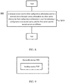
- FIG. 2 shows a schematic flowchart of a method 200 for transmitting information according to an embodiment of the present invention.
- the method 200 may be performed by a network device, for example, the network device may be the base station 21 in FIG. 1 .
- the method 200 includes the act S210.
- a network device sends first configuration information to a terminal device through a first control channel on a first carrier, wherein the first configuration information is used for indicating a configuration on a second carrier, and the first carrier and the second carrier are different.
- the network device may indicate configuration information of resources of other carriers (such as the second carrier) through a channel (such as the first control channel) on the first carrier, and send relevant configuration information (such as the first configuration information) to the terminal device.
- the network device does not need to transmit a common control channel on each carrier, and the overhead of the common control channel is saved.
- the terminal device may receive the first configuration information sent by the network device through the first control channel of a carrier to obtain configuration information of multiple carriers, so as to avoid a detection of the common control channel on the multiple carriers, reduce the complexity of the terminal device and save the power of the terminal device.
- the first carrier and the second carrier are different carriers, such as a low-frequency carrier and a high-frequency carrier.
- the problem of insufficient coverage of a common control channel on the high-frequency carriers can be solved by sending the configuration information of the high-frequency carriers through the common control channel on the low-frequency carrier. Therefore, with the technical solution of the embodiment of the present invention, the coverage capability of the common control channels on the high-frequency carriers can be further equivalently improved.
- the first configuration information may indicate various configuration information of resources of the second carrier, such as slot structure information, reserved resources, and resource pool information. It should be understood that the first configuration information may include various configuration information of the resources of the second carrier, which are not restricted in the present invention.
- the first configuration information may be configuration information of a second control channel of resources of the second carrier.
- the first configuration information may indicate a related configuration of the second control channel of time-frequency resources of the second carrier.
- the first control channel may be a common control channel and the second channel may be a UE-specific control channel. That is, the network device may indicate the relevant configuration of the UE-specific control channel on the second carrier through the common control channel on the first carrier.
- the first configuration information may include at least one of serial number information of a time domain scheduling unit in which the second control channel is located, information of a resource used by the second control channel, and information of a numerology used by the second control channel.
- the time domain scheduling unit may be specifically a time slot, a mini-slot, or a sub-frame.
- the first control channel and the second control channel may adopt different carriers. That is, the carrier adopted by the common control channel and the carrier adopted by the UE-specific control channel of the terminal may be different.
- the numerology adopted by the second control channel may be indicated in the information of a resource used by the second control channel, or it may also be indicated by the network device through other implicit forms.
- the network device sends first configuration information to the terminal device through the first control channel on the first carrier, wherein the first configuration information is used for indicating the configuration on the second carrier, and the first carrier and the second carrier are different, and the overhead of the common control channel can be saved.
- the first configuration information may be configuration information of resources on the second carrier.
- the first configuration information may include: at least one of structural information of a time domain scheduling unit within resources of the second carrier, reserved resource information of resources of the second carrier, and resource pool information of resources of the second carrier.
- the first configuration information may include structural information of a time domain scheduling unit within time-frequency resources of the second carrier, wherein, the structure of the time domain scheduling unit within the resources of the second carrier may include information such as an uplink resource part, a downlink resource part, or a length of a protection period GAP.
- the first configuration information may include reserved resource information of the time-frequency resources of the second carrier.
- the first configuration information may include resource pool information within the time-frequency resources of the second carrier.
- the first configuration information only shows some examples of the first configuration information, and there may be more forms of combination in specific implementations, or the first configuration information may further include other reasonable configuration information, and this is not restricted in the present invention.
- the first control channel may further carry indication information used for indicating a serial number of a time domain scheduling unit corresponding to the first configuration information.
- the network device when the network device sends the configuration information through the first control channel, that the configuration information is to be sent to which time domain scheduling unit (such as to which sub-frame, time slot or mini-slot) may further be specified.
- the network device may indicate the time domain scheduling unit corresponding to the configuration information to the terminal device by carrying the serial number of the time domain scheduling unit in the first configuration information.
- a serial number of each mini-slot in the time slot may also be indicated, and this is not restricted in the present invention.
- the first configuration information is only taken as an example for explanation, and multiple pieces of configuration information may be introduced in practice, and this is not restricted in the present invention.
- the information included in the first configuration information may be sent through the same configuration information or may be sent in different configuration information, and this is not restricted in the present invention.
- FIG. 3A represents a common control channel on carrier 1, and represents a UE-specific control channel on carrier 2.
- the common control channel on carrier 1 may be understood as the first control channel described above.
- the network device may indicate the UE-specific control channel on other carrier (such as carrier 2) through the common control channel on carrier 1.
- the network device may also indicate the UE-specific control channel on carrier 1 through the common control channel on carrier 1.
- Each of multiple pieces of indication information shown in FIG. 3A may be understood as the first configuration information described above.
- the network device may further indicate other configuration information (not shown) on carrier 1 and carrier 2 in FIG. 3A , which are not restricted in the present invention.
- the terminal device may receive the first configuration information sent by the network device through the first control channel of a carrier to obtain configuration information of multiple carriers, so as to avoid a detection of a common control channel on the multiple carriers, reduce the complexity of the terminal device, and save the power of the terminal device.
- FIG. 3B represents a common control channel on carrier 1, and represents UE-specific control channels corresponding to multiple time-frequency units on carrier 2.
- the network device may indicate the UE-specific control channels of multiple time-frequency scheduling units (such as time-frequency scheduling unit 1, time-frequency scheduling unit 2, time-frequency scheduling unit 3, and time-frequency scheduling unit 4) on carrier 2 through the common control channel on carrier 1.
- time-frequency scheduling units such as time-frequency scheduling unit 1, time-frequency scheduling unit 2, time-frequency scheduling unit 3, and time-frequency scheduling unit 4
- multiple pieces indication information in FIG. 3B may be understood as the first configuration information previously mentioned.
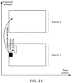
- FIG. 4A represents a common control channel on carrier 1.
- other various configuration information on carrier 2 which is not limited to a UE-specific control channel, may be indicated by the network device through the common control channel on carrier 1.
- the indication information in FIG. 4A may be understood as the first configuration information previously mentioned.
- FIG. 4B represents a common control channel on carrier 1.
- other various configuration information in each time-frequency scheduling unit such as time-frequency scheduling unit 1, time-frequency scheduling unit 2, time-frequency scheduling unit 3, and time-frequency scheduling unit 4 on carrier 2, which is not limited to a UE-specific control channel, may be indicated by the network device through the common control channel on carrier 1.
- various indication information in FIG. 4B may be understood as the first configuration information previously mentioned.
- FIG. 3A , FIG. 3B , FIG. 4A and FIG. 4B are introduced herein only for the convenience of understanding the technical solutions of embodiments of the present invention by those skilled in the art, which does not constitute limitation on the present invention.
- FIG. 5 shows an illustrative flow chart of a method 500 for transmitting information according to another embodiment of the present invention.
- the method 500 may be performed by a network device, for example, the network device may be the base station 21 in FIG. 1 .
- the method 500 includes the act S510.
- a network device sends first configuration information to a terminal device through system information on a first carrier, wherein the first configuration information is used for indicating a configuration on the second carrier, and the first carrier and the second carrier are different.
- system information may be understood as system broadcast information.
- the first control channel and the second control channel are not distinguished, but the related configuration information is sent to the terminal device through the system information.
- system information in the embodiment of the present invention may correspond to the "first control channel” in the preceding method 200
- control channel in the embodiment of the present invention may correspond to the "second control channel” in the preceding method 200.
- the network device may send the first configuration information to the terminal device through the system information on the first carrier, wherein the first configuration information is used for indicating the configuration on the second carrier, and the first carrier is different from the second carrier.
- the network device does not need to send all of system information on each carrier, which saves the overhead of the system information.
- the terminal device may receive the first configuration information sent by the network device through the system information on the first carrier, so as to obtain configurations of multiple carriers according to the first configuration information, thus avoiding the detection of the system information of the multiple carriers, reducing the complexity of the terminal device, and saving the power of the terminal device.
- the first configuration information is configuration information of a control channel on the second carrier.
- the first configuration information includes at least one of serial number information of a time domain scheduling unit in which the control channel is located, information of a resource used by the control channel, and information of a numerology used by the control channel.
- the time domain scheduling unit includes a time slot, mini-slot, or a sub-frame.
- the first configuration information may be resource allocation information of resources on the second carrier.
- the first configuration information may include at least one of structure information of a time domain scheduling unit within resources of the second carrier, reserved resource information of resources of the second carrier, and resource pool information of resources of the second carrier.
- the system information carries indication information used for indicating a serial number of a time domain scheduling unit corresponding to the first configuration information.
- the network device sends the first configuration information to the terminal device through system information on the first carrier, wherein the first configuration information is used for indicating the configuration on a second carrier, and the first carrier is different from the second carrier, the network device does not need to send all of system information on each carrier, thus saving the overhead of the system information.
- FIG. 6A represents system broadcast information (located within the resources of carrier 1) and represents a control channel corresponding to each carrier (such as carrier 1 and carrier 2).
- the network device may transmit control channels of other carriers (such as carrier 1 and carrier 2) to the terminal device through system broadcast information.
- the network device may further send other configuration information (such as the first configuration information) to the terminal device through the system broadcast information, and this is not restricted in the present invention.
- the indication information in FIG. 6A may also be understood as the first configuration information or other configuration information.
- FIG. 6B represents system broadcast information (located in the resources using subcarrier interval f1), and represents a control channel corresponding to a time domain scheduling unit (such as time domain scheduling unit 1, time domain scheduling unit 2, time domain scheduling unit 3, time domain scheduling unit 4, or time domain scheduling unit 5) in each carrier (such as carrier 1 or carrier 2).
- the network device may transmit control channels of time domain scheduling units of other carriers to the terminal device through the system broadcast information.
- the network device may send other configuration information (such as the first configuration information) to the terminal device through system broadcast information, and this is not restricted in the present invention.
- multiple pieces of indication information in FIG. 6B may also be understood as the first configuration information or other configuration information.
- the network device sends first configuration information (i.e., indication information) to the terminal device through system broadcast information on the first carrier, wherein the first configuration information is used for indicating the configuration within the resources of the second carrier, and the first carrier is different from the second carrier, and the overhead of common control channel can be saved.
- first configuration information i.e., indication information
- FIG. 7 shows a schematic flowchart of a method 700 for transmitting information according to an embodiment of the present invention.
- the method 700 may be performed by a terminal device, for example, the terminal device may be the terminal device 11, or the terminal device 12, or the terminal device 13 in FIG. 1 .
- the method 700 may correspond to the preceding method 200.
- the method 700 includes the act S710.
- a terminal device receives first configuration information sent by a network device through a first control channel on a first carrier, wherein the first configuration information is used for indicating a configuration on a second carrier, and the first carrier and the second carrier are different.
- the terminal device receives the first configuration information sent by the network device through the first control channel on the first carrier, wherein the first configuration information is used for indicating the configuration on the second carrier, the first carrier is different from the second carrier.
- the terminal device can receive the first configuration information sent by the network device through the first control channel of a carrier to obtain configuration information of multiple carriers, so as to avoid a detection of a common control channels on the multiple carriers, reduce the complexity of the terminal device, and save the power of the terminal device.
- the first configuration information is configuration information of a second control channel on the second carrier.
- the first control channel is a common control channel and the second control channel is a UE-specific control channel of the terminal device.
- the first configuration information includes at least one of serial number information of a time domain scheduling unit in which the second control channel is located, information of a resource used by the second control channel, and information of a numerology used by the second control channel.
- the first configuration information is resource configuration information of resources of the second carrier.
- the first configuration information includes at least one of structure information of a minimum time domain scheduling unit within resources of the second carrier, reserved resource information of resources of the second carrier, and resource pool information of resources of the second carrier.
- the first control channel carries indication information used for indicating a serial number of a time domain scheduling unit corresponding to the first configuration information.
- the time domain scheduling unit includes a time slot, a mini-slot, or a sub-frame.
- the numerology used by the second control channel includes at least one of the following parameters: a subcarrier interval, a width of minimum frequency domain scheduling unit, a length of orthogonal frequency division multiplexing (OFDM) symbol, a length of minimum time domain scheduling unit, and a length of Cyclic Prefix (CP).
- a subcarrier interval a width of minimum frequency domain scheduling unit
- a length of orthogonal frequency division multiplexing (OFDM) symbol a length of minimum time domain scheduling unit
- CP Cyclic Prefix
- the terminal device receives the first configuration information sent by the network device through the first control channel on the first carrier, wherein the first configuration information is used for indicating the configuration on the second carrier, and the first carrier and the second carrier are different, so that the overhead of common control channel can be saved, the complexity of the terminal device can be reduced, and the power of the terminal device can be saved.
- FIG. 8 shows a schematic flowchart of a method 800 for transmitting information according to an embodiment of the present invention.
- the method 800 may be performed by a terminal device, for example, the terminal device may be the terminal device 11, or the terminal device 12, or the terminal device 13 in FIG. 1 .
- the method 800 may correspond to the preceding method 500.
- the method 800 includes the act S810.
- a terminal device receives first configuration information sent by a network device through system information on a first carrier, wherein the first configuration information is used for indicating a configuration on a second carrier, and the first carrier and the second carrier are different.
- the terminal device may receive the first configuration information sent by the network device through the system information on the first carrier, so as to obtain configurations of multiple carriers according to the first configuration information, thus avoiding the detection of system information of the multiple carriers, reducing the complexity of the terminal device, and saving the power of the terminal device.
- the first configuration information is configuration information of a control channel on the second carrier.
- the first configuration information includes at least one of serial number information of a time domain scheduling unit in which the control channel is located, information of a resource used by the control channel, and information of a numerology used by the control channel.
- the time domain scheduling unit includes a time slot, a mini-slot, or a sub-frame.
- the first configuration information is resource allocation information of resources of the second carrier.
- the first configuration information may include at least one of structure information of a time domain scheduling unit within resources of the second carrier, reserved resource information of resources of the second carrier, and resource pool information of resources of the second carrier.
- the system information carries indication information used for indicating a serial number of a time domain scheduling unit corresponding to the first configuration information.
- the time domain scheduling unit includes a time slot, a mini-slot, or a sub-frame.
- the numerology used by the control channel includes at least one of the following parameters: a subcarrier interval, a width of frequency domain scheduling unit, a length of orthogonal frequency division multiplexing (OFDM) symbol, a length of minimum domain scheduling unit, and a length of cyclic prefix (CP).
- a subcarrier interval a width of frequency domain scheduling unit
- a length of orthogonal frequency division multiplexing (OFDM) symbol a length of minimum domain scheduling unit
- CP cyclic prefix
- the terminal device may receive the first configuration information sent by the network device through the system information on the first carrier, so as to obtain the configurations of multiple carriers according to the first configuration information, thus avoiding a detection of system information of the multiple carriers, reducing the complexity of the terminal device, and saving the power of the terminal device.
- FIG. 9 shows a network device 900 according to an embodiment of the present invention.
- the network device 900 includes a sending module 910.
- the sending module 910 is used for sending first configuration information to a terminal device through a first control channel on a first carrier, wherein the first configuration information is used for indicating a configuration on a second carrier, and the first carrier and the second carrier are different.
- the first configuration information is configuration information of a second control channel on the second carrier.
- the first control channel is a common control channel
- the second control channel is a UE-specific control channel of the terminal device.
- the first configuration information includes at least one of serial number information of a time domain scheduling unit in which the second control channel is located, information of a resource used by the second control channel, and information of a numerology used by the second control channel.
- the first configuration information is resource configuration information of resources of the second carrier.
- the first configuration information may include at least one of structure information of a time domain scheduling unit within resources of the second carrier, reserved resource information of resources of the second carrier, and resource pool information of resources of the second carrier.
- the first control channel carries indication information used for indicating a serial number of a time domain scheduling unit corresponding to the first configuration information.
- the time domain scheduling unit includes a time slot, a mini-slot, or a sub-frame.
- the network device 900 may perform the method 200 for transmitting information according to the embodiment of the present invention, and the above and other operations and/or functions of various units in the network device 900 are respectively for implementing the corresponding flows of the various methods mentioned above, which will not be described here in detail for sake of conciseness.
- the network device 900 sends first configuration information to a terminal device through a first control channel on a first carrier, wherein the first configuration information is used for indicating a configuration on a second carrier, and the first carrier and the second carrier are different.
- the network device 900 does not need to transmit a common control channel on each carrier, thus saving the overhead of common control channel.
- FIG. 10 shows a network device 1000 according to another embodiment of the present invention.
- the network device 1000 includes a sending module 1010.
- the sending module 1010 is used for sending first configuration information to a terminal device through system information on a first carrier, wherein the first configuration information is used for indicating a configuration on a second carrier, and the first carrier and the second carrier are different.
- the first configuration information is configuration information of a control channel on the second carrier.
- the first configuration information includes at least one of serial number information of a time domain scheduling unit in which the control channel is located, information of a resource used by the control channel, and information of a numerology used by the control channel.
- the first configuration information is resource allocation information of resources of the second carrier.
- the first configuration information may include at least one of structure information of a time domain scheduling unit within resources of the second carrier, reserved resource information of resources of the second carrier, and resource pool information of resources of the second carrier.
- the system information carries indication information used for indicating a serial number of a time domain scheduling unit corresponding to the first configuration information.
- the time domain scheduling unit includes a time slot, mini-slot, or a sub-frame.
- the network device 1000 may perform the method 500 for transmitting information according to the embodiment of the present invention, and the above and other operations and/or functions of various units in the network device 1000 are respectively for implementing the corresponding flows of the various methods mentioned above, which will not be described here in detail for sake of conciseness.
- the network device 1000 sends the first configuration information to a terminal device through system information on a first carrier, wherein the first configuration information is used for indicating the configuration on a second carrier, and the first carrier and the second carrier are different.
- the network device does not need to send all of system information on each carrier, thus saving the overhead of the system information.
- FIG. 11 shows a terminal device 1100 according to an embodiment of the present invention. For sake of conciseness, some similar terms, definitions or concepts will not be repeated. As illustrated in FIG. 11 , the terminal device 1100 includes a receiving module 1110.
- the receiving module 1110 is used for receiving first configuration information sent by a network device through a first control channel on a first carrier, wherein the first configuration information is used for indicating a configuration on a second carrier, and the first carrier and the second carrier are different.
- the receiving module 1110 is further used for: receiving the first configuration information sent by the network device through the first control channel on the first carrier, wherein the first configuration information is resource configuration information of resources of the second carrier.
- the terminal device 1100 may perform the method 700 for transmitting information according to the embodiment of the present invention, and the above and other operations and/or functions of various units in the terminal device 1100 are respectively for implementing the corresponding flows of the various methods mentioned above, which will not be described here in detail for sake of conciseness.
- the terminal device 1100 receives first configuration information sent by a network device through a first control channel on a first carrier, wherein the first configuration information is used for indicating the configuration on the second carrier, and the first carrier is different from the second carrier, and the overhead of common control channel can be saved and the power of the terminal device can be saved.
- FIG. 12 shows a terminal device 1200 according to an embodiment of the present invention. For sake of conciseness, some similar terms, definitions or concepts will not be repeated. As illustrated in FIG. 12 , the terminal device 1200 includes a receiving module 1210.
- the receiving module 1210 is used for receiving first configuration information sent by a network device through system information on a first carrier, wherein the first configuration information is used for indicating a configuration on a second carrier, and the first carrier and the second carrier are different.
- the terminal device 1200 may perform the method 800 for transmitting information according to the embodiment of the present invention, and the above and other operations and/or functions of various units in the terminal device 1200 are respectively for implementing the corresponding flows of the various methods mentioned above, which will not be described here in detail for sake of conciseness.
- the terminal device 1200 receives the first configuration information sent by a network device through the system information on the first carrier, wherein the first configuration information is used for indicating the configuration on the second carrier, and the first carrier and the second carrier are different.
- the terminal device may receive the first configuration information sent by the network device through the system information on the first carrier, so as to obtain configurations of multiple carriers according to the first configuration information, thus avoiding a detection of the system information of the multiple carriers, reducing the complexity of the terminal device, and saving the power of the terminal device.
- FIG. 13 shows a structure of a network device provided according to an embodiment of the present invention, which includes at least one processor 1302 (e.g., CPU), at least one network interface 1303 or another communication interface, and a memory 1304.
- the network device may also include a receiver 1305 and a transmitter 1306.
- the processor 1302 is used for executing an executable module, such as a computer program, stored in the memory 1304.
- the memory 1304 may include high-speed Random Access Memory (RAM) or non-volatile memory, such as at least one disk memory. Communication connection with at least one of other network elements is realized through at least one network interface 1303 (which may be wired or wireless).
- Receiver 1305 and transmitter 1306 are used for transmitting various signals or information.
- the memory 1304 stores a program 13041 that may be executed by the processor 1302 for implementing a method of a network device side of an embodiment of the present invention described above.
- the transmitter 1306 sends first configuration information to a terminal device through a first control channel on a first carrier, wherein the first configuration information is used for indicating a configuration on a second carrier, and the first carrier and the second carrier are different.
- FIG. 14 shows a structure of a network device provided according to another embodiment of the present invention, which includes at least one processor 1402 (e.g., CPU), at least one network interface 1403 or another communication interface, and a memory 1404.
- the network device may also include a receiver 1405 and a transmitter 1406.
- the processor 1402 is used for executing an executable module, such as a computer program, stored in the memory 1404.
- the memory 1404 may include high-speed Random Access Memory (RAM) or non-volatile memory, such as at least one disk memory. Communication connection with at least one of other network elements is realized through at least one network interface 1403 (which may be wired or wireless).
- Receiver 1405 and transmitter 1406 are used for transmitting various signals or information.
- the memory 1404 stores a program 14041, which may be executed by the processor 1402 for implementing a method of a network device side of an embodiment of the present invention described above.
- the transmitter 1406 sends first configuration information to a terminal device through system information on a first carrier, wherein the first configuration information is used for indicating a configuration on a second carrier, and the first carrier and the second carrier are different.
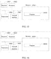
- FIG. 15 shows a structure of a terminal device provided according to another embodiment of the present invention, which includes at least one processor 1502 (e.g., CPU), at least one network interface 1503 or another communication interface, and a memory 1504.
- the terminal device may also include a receiver 1505 and a transmitter 1506.
- the processor 1502 is used for executing an executable module, such as a computer program, stored in the memory 1504.
- the memory 1504 may include high-speed Random Access Memory (RAM) or non-volatile memory, such as at least one disk memory. Communication connection with at least one of other network elements is realized through at least one network interface 1503 (which may be wired or wireless).
- Receiver 1505 and transmitter 1506 are used for transmitting various signals or information.
- the memory 1504 stores a program 15041 that can be executed by the processor 1502 for implementing a method of a terminal device side of an embodiment of the present invention described above.
- the receiver 1505 receives first configuration information sent by a network device through a first control channel on a first carrier, wherein the first configuration information is used for indicating a configuration on a second carrier, and the first carrier and the second carrier are different.
- FIG. 16 shows a structure of a terminal device provided according to an embodiment of the present invention, which includes at least one processor 1602 (e.g., CPU), at least one network interface 1603 or another communication interface, and a memory 1604.
- the terminal device may also include a receiver 1605 and a transmitter 1606.
- the processor 1602 is used for executing executable modules, such as computer programs, stored in the memory 1604.
- the memory 1604 may include high-speed Random Access Memory (RAM) or non-volatile memory, such as at least one disk memory. Communication connection with at least one of other network elements is realized through at least one network interface 1603 (which may be wired or wireless).
- Receiver 1605 and transmitter 1606 are used for transmitting various signals or information.
- the memory 1604 stores a program 16041 that can be executed by the processor 1602 for implementing a method of the terminal device side of an embodiment of the present invention described above.
- the receiver 1605 receives first configuration information sent by a network device through system information on a first carrier, wherein the first configuration information is used for indicating a configuration on a second carrier, and the first carrier and the second carrier are different.
- the disclosed system, apparatus and method may be implemented in other ways.
- the apparatus embodiments described above are only illustrative, for example, the division of the units is only a logical function division, and there may be other division manners in actual implementation.
- multiple units or components may be combined or integrated into another system, or some features may be ignored or not executed.
- the mutual coupling or direct coupling or communication connection shown or discussed may be indirect coupling or communication connection through some interface, apparatus or unit, and may be electrical, mechanical or in other forms.
- the unit described as a separate component may or may not be physically separated, and the component shown as a unit may or may not be a physical unit, i.e., it may be located in one place or may be distributed over multiple network units. Some or all of the units may be selected according to practical needs to achieve a purpose of embodiments.
- various functional units in various embodiments of the present invention may be integrated in one processing unit, or various units may be physically present separately, or two or more units may be integrated in one unit.
- the functions may be stored in a computer readable storage medium if implemented in a form of software functional units and sold or used as a separate product.
- the technical solution of embodiments of the present invention in essence, or the part contributing to the related art, or the part of the technical solution, may be embodied in the form of a software product stored in a storage medium, including several instructions for causing a computer device (which may be a personal computer, a server, or a network device, etc.) to perform all or part of the acts of the methods described in various embodiments of the present invention.
- the aforementioned storage media include various media capable of storing program codes such as U disk, mobile hard disk, read-only memory (ROM), random access memory (RAM), magnetic disk or optical disk.
Landscapes
- Engineering & Computer Science (AREA)
- Signal Processing (AREA)
- Computer Networks & Wireless Communication (AREA)
- Mobile Radio Communication Systems (AREA)
- Two-Way Televisions, Distribution Of Moving Picture Or The Like (AREA)
Applications Claiming Priority (1)
| Application Number | Priority Date | Filing Date | Title |
|---|---|---|---|
| PCT/CN2016/111838 WO2018112934A1 (fr) | 2016-12-23 | 2016-12-23 | Procédé de transmission d'informations, dispositif de réseau et dispositif terminal |
Publications (3)
| Publication Number | Publication Date |
|---|---|
| EP3544346A1 true EP3544346A1 (fr) | 2019-09-25 |
| EP3544346A4 EP3544346A4 (fr) | 2019-11-20 |
| EP3544346B1 EP3544346B1 (fr) | 2024-10-09 |
Family
ID=62624638
Family Applications (1)
| Application Number | Title | Priority Date | Filing Date |
|---|---|---|---|
| EP16924530.5A Active EP3544346B1 (fr) | 2016-12-23 | 2016-12-23 | Procédé de transmission d'informations, dispositif de réseau et dispositif terminal |
Country Status (15)
| Country | Link |
|---|---|
| US (1) | US11777684B2 (fr) |
| EP (1) | EP3544346B1 (fr) |
| JP (1) | JP7097890B2 (fr) |
| KR (1) | KR20190099214A (fr) |
| CN (2) | CN110115076B (fr) |
| AU (1) | AU2016433342B2 (fr) |
| CA (1) | CA3047658C (fr) |
| IL (1) | IL267551B2 (fr) |
| MX (1) | MX2019007149A (fr) |
| MY (1) | MY202704A (fr) |
| PH (1) | PH12019501400A1 (fr) |
| RU (1) | RU2732723C1 (fr) |
| TW (1) | TWI757382B (fr) |
| WO (1) | WO2018112934A1 (fr) |
| ZA (1) | ZA201904010B (fr) |
Families Citing this family (4)
| Publication number | Priority date | Publication date | Assignee | Title |
|---|---|---|---|---|
| RU2737792C1 (ru) * | 2016-12-23 | 2020-12-03 | Гуандун Оппо Мобайл Телекоммьюникейшнз Корп., Лтд. | Способ передачи информации, сетевое устройство и оконечное устройство |
| CN110115076B (zh) | 2016-12-23 | 2020-12-29 | Oppo广东移动通信有限公司 | 传输信息的方法、网络设备和终端设备及计算机可读介质 |
| WO2020181441A1 (fr) * | 2019-03-08 | 2020-09-17 | 华为技术有限公司 | Procédé, dispositif et système de communication |
| US11477760B2 (en) * | 2019-12-19 | 2022-10-18 | Qualcomm Incorporated | Frequency diversity techniques for single frequency networks |
Family Cites Families (35)
| Publication number | Priority date | Publication date | Assignee | Title |
|---|---|---|---|---|
| KR20100014091A (ko) * | 2008-08-01 | 2010-02-10 | 엘지전자 주식회사 | 다중 반송파 시스템에서 데이터 전송 방법 |
| KR101667826B1 (ko) * | 2008-11-04 | 2016-10-19 | 애플 인크. | 제 1 캐리어에서 제 2, 다른 캐리어에서의 제어 정보를 표시하기 위해 다운링크 제어 구조를 제공하는 방법 |
| US8432859B2 (en) * | 2009-06-22 | 2013-04-30 | Alcatel Lucent | Indicating dynamic allocation of component carriers in multi-component carrier systems |
| CN102026375B (zh) * | 2009-09-11 | 2013-10-23 | 中国移动通信集团公司 | 一种系统信息发送的方法、系统和设备 |
| US8902828B2 (en) * | 2009-10-05 | 2014-12-02 | Qualcomm Incorporated | Carrier indicator field for cross carrier assignments |
| CN102088433B (zh) | 2009-12-08 | 2015-01-28 | 中兴通讯股份有限公司 | 多载波系统中分量载波激活去激活的优化方法和系统 |
| CN102149208B (zh) | 2010-02-05 | 2013-11-06 | 华为技术有限公司 | 载波激活相关信息的处理方法、基站及ue |
| CN102685891B (zh) * | 2011-03-09 | 2017-04-26 | 中兴通讯股份有限公司 | 一种无线通信系统中载波聚合的实现方法及系统 |
| CN102769903B (zh) | 2011-05-02 | 2016-04-06 | 上海贝尔股份有限公司 | 一种触发从小区时间对齐过程的方法 |
| ES2838154T3 (es) * | 2011-05-03 | 2021-07-01 | Nokia Solutions & Networks Oy | Señalización de control en sistemas de agregación de portadora |
| US9007972B2 (en) | 2011-07-01 | 2015-04-14 | Intel Corporation | Communication state transitioning control |
| CN105391517B (zh) * | 2011-07-28 | 2018-05-04 | 华为技术有限公司 | 控制信道的接收和发送方法和装置 |
| US20130064216A1 (en) * | 2011-09-12 | 2013-03-14 | Research In Motion Limited | DMRS Association and Signaling for Enhanced PDCCH in LTE Systems |
| US9179456B2 (en) | 2012-02-07 | 2015-11-03 | Samsung Electronics Co., Ltd. | Methods and apparatus for downlink control channels transmissions in wireless communications systems |
| EP2816855B1 (fr) * | 2012-05-09 | 2018-06-27 | Sun Patent Trust | Planification inter-porteuses dans des canaux de type E-PDCCH |
| US9749094B2 (en) | 2012-06-14 | 2017-08-29 | Sharp Kabushiki Kaisha | Devices for sending and receiving feedback information |
| JP6143153B2 (ja) * | 2012-08-01 | 2017-06-07 | シャープ株式会社 | 基地局、端末、通信方法および集積回路 |
| CN104348602B (zh) * | 2013-08-09 | 2019-06-18 | 北京三星通信技术研究有限公司 | 一种混合双工通信方法、基站及终端 |
| US9992002B2 (en) | 2013-08-09 | 2018-06-05 | Kyocera Corporation | User terminal, radio access network, and communication control method |
| WO2015037250A1 (fr) | 2013-09-16 | 2015-03-19 | Nec Corporation | Procédés et appareils liés à agrégation de porteuses inter-système lte fdd-tdd, dans des systèmes de communications sans fil avancés |
| CN104469950B (zh) * | 2013-09-23 | 2018-09-04 | 电信科学技术研究院 | 一种发送和接收数据的方法、系统及设备 |
| JP6388768B2 (ja) | 2014-01-14 | 2018-09-12 | 株式会社Nttドコモ | ユーザ端末、無線基地局及び無線通信方法 |
| WO2015123834A1 (fr) | 2014-02-20 | 2015-08-27 | Qualcomm Incorporated | Configuration de duplexage dans le domaine temporel pour eimta |
| CN104901775B (zh) * | 2014-03-09 | 2018-12-21 | 上海朗帛通信技术有限公司 | 一种在非授权频谱上的通信方法和装置 |
| CN104010373A (zh) * | 2014-06-09 | 2014-08-27 | 宇龙计算机通信科技(深圳)有限公司 | 用于移动通信的载波配置方法、配置系统和基站 |
| EP3176962B1 (fr) * | 2014-07-28 | 2020-10-14 | LG Electronics Inc. | Procédé et appareil d'émission-réception de signal sans fil dans un système de communication sans fil |
| WO2016171471A1 (fr) * | 2015-04-20 | 2016-10-27 | 엘지전자 주식회사 | Procédé pour une opération de dispositif à dispositif (d2d) réalisée par un terminal dans un système de communication sans fil et terminal utilisant le procédé |
| CN105979597B (zh) * | 2016-06-27 | 2020-02-21 | 宇龙计算机通信科技(深圳)有限公司 | 通信资源的分配方法、分配装置、基站和终端 |
| KR102581594B1 (ko) * | 2016-07-19 | 2023-09-25 | 삼성전자 주식회사 | 무선 통신 시스템에서 반송파 집적 방법 및 장치 |
| CN106231677B (zh) | 2016-07-29 | 2020-01-10 | 宇龙计算机通信科技(深圳)有限公司 | 一种通信的方法及基站 |
| CN110115076B (zh) | 2016-12-23 | 2020-12-29 | Oppo广东移动通信有限公司 | 传输信息的方法、网络设备和终端设备及计算机可读介质 |
| CL2018001451A1 (es) | 2018-05-30 | 2018-07-27 | Guangdong Oppo Mobile Telecommunications Corp Ltd | Un método y equipo terminal para establecer una conexión de comunicaciones |
| CL2019000193A1 (es) | 2019-01-25 | 2019-04-22 | Guangdong Oppo Mobile Telecommunications Corp Ltd | Método para la transmisión de información y aparato para la transmisión de información |
| CL2019000803A1 (es) | 2019-03-27 | 2019-06-28 | Guangdong Oppo Mobile Telecommunications Corp Ltd | Método para gestionar un haz de onda, dispositivo terminal y dispositivo de red |
| CL2019000817A1 (es) | 2019-03-28 | 2019-06-28 | Guangdong Oppo Mobile Telecommunications Corp Ltd | Método de transmisión de señales, dispositivo de red y dispositivo terminal |
-
2016
- 2016-12-23 CN CN201680091850.4A patent/CN110115076B/zh active Active
- 2016-12-23 RU RU2019121989A patent/RU2732723C1/ru active
- 2016-12-23 MY MYPI2019003517A patent/MY202704A/en unknown
- 2016-12-23 MX MX2019007149A patent/MX2019007149A/es unknown
- 2016-12-23 KR KR1020197017493A patent/KR20190099214A/ko not_active Ceased
- 2016-12-23 CA CA3047658A patent/CA3047658C/fr active Active
- 2016-12-23 AU AU2016433342A patent/AU2016433342B2/en active Active
- 2016-12-23 US US16/470,939 patent/US11777684B2/en active Active
- 2016-12-23 WO PCT/CN2016/111838 patent/WO2018112934A1/fr not_active Ceased
- 2016-12-23 EP EP16924530.5A patent/EP3544346B1/fr active Active
- 2016-12-23 IL IL267551A patent/IL267551B2/en unknown
- 2016-12-23 CN CN202011450128.XA patent/CN112600655A/zh active Pending
- 2016-12-23 JP JP2019532709A patent/JP7097890B2/ja active Active
-
2017
- 2017-11-29 TW TW106141709A patent/TWI757382B/zh active
-
2019
- 2019-06-19 PH PH12019501400A patent/PH12019501400A1/en unknown
- 2019-06-20 ZA ZA2019/04010A patent/ZA201904010B/en unknown
Also Published As
| Publication number | Publication date |
|---|---|
| EP3544346A4 (fr) | 2019-11-20 |
| JP7097890B2 (ja) | 2022-07-08 |
| WO2018112934A1 (fr) | 2018-06-28 |
| ZA201904010B (en) | 2020-12-23 |
| CN110115076B (zh) | 2020-12-29 |
| IL267551B2 (en) | 2023-09-01 |
| TWI757382B (zh) | 2022-03-11 |
| EP3544346B1 (fr) | 2024-10-09 |
| CA3047658C (fr) | 2022-09-06 |
| CN110115076A (zh) | 2019-08-09 |
| IL267551A (fr) | 2019-08-29 |
| AU2016433342B2 (en) | 2022-05-12 |
| US20200092064A1 (en) | 2020-03-19 |
| CA3047658A1 (fr) | 2018-06-28 |
| PH12019501400A1 (en) | 2020-02-10 |
| RU2732723C1 (ru) | 2020-09-22 |
| IL267551B1 (en) | 2023-05-01 |
| TW201824801A (zh) | 2018-07-01 |
| AU2016433342A1 (en) | 2019-07-04 |
| KR20190099214A (ko) | 2019-08-26 |
| US11777684B2 (en) | 2023-10-03 |
| JP2020504941A (ja) | 2020-02-13 |
| MX2019007149A (es) | 2019-08-16 |
| BR112019012437A2 (pt) | 2020-04-14 |
| CN112600655A (zh) | 2021-04-02 |
| MY202704A (en) | 2024-05-16 |
Similar Documents
| Publication | Publication Date | Title |
|---|---|---|
| US11758553B2 (en) | Signal transmission method, terminal device and network device for resource reservation | |
| US11528728B2 (en) | Information transmission method and device | |
| CN108347778A (zh) | 通信方法及装置 | |
| WO2018018510A1 (fr) | Procédé de transmission de signal pilote, équipement terminal, et équipement de réseau | |
| US11777773B2 (en) | Information transmission method, network device and terminal device | |
| WO2019029346A1 (fr) | Procédé d'émission de signal de référence et dispositif de communication | |
| TW201806326A (zh) | 傳輸數據的方法和設備 | |
| US11777684B2 (en) | Information transmission method, network device and terminal device | |
| CN107734685A (zh) | 一种控制信道传输方法、装置及系统 | |
| HK40008911B (en) | Information transmission method, network device and terminal device and computer readable medium | |
| HK40008911A (en) | Information transmission method, network device and terminal device and computer readable medium | |
| BR112019012437B1 (pt) | Método de transmissão de informações, dispositivo de rede e dispositivo terminal |
Legal Events
| Date | Code | Title | Description |
|---|---|---|---|
| STAA | Information on the status of an ep patent application or granted ep patent |
Free format text: STATUS: THE INTERNATIONAL PUBLICATION HAS BEEN MADE |
|
| PUAI | Public reference made under article 153(3) epc to a published international application that has entered the european phase |
Free format text: ORIGINAL CODE: 0009012 |
|
| STAA | Information on the status of an ep patent application or granted ep patent |
Free format text: STATUS: REQUEST FOR EXAMINATION WAS MADE |
|
| 17P | Request for examination filed |
Effective date: 20190618 |
|
| AK | Designated contracting states |
Kind code of ref document: A1 Designated state(s): AL AT BE BG CH CY CZ DE DK EE ES FI FR GB GR HR HU IE IS IT LI LT LU LV MC MK MT NL NO PL PT RO RS SE SI SK SM TR |
|
| AX | Request for extension of the european patent |
Extension state: BA ME |
|
| A4 | Supplementary search report drawn up and despatched |
Effective date: 20191017 |
|
| RIC1 | Information provided on ipc code assigned before grant |
Ipc: H04W 72/04 20090101AFI20191011BHEP |
|
| RAP1 | Party data changed (applicant data changed or rights of an application transferred) |
Owner name: GUANGDONG OPPO MOBILE TELECOMMUNICATIONS CORP., LT |
|
| DAV | Request for validation of the european patent (deleted) | ||
| DAX | Request for extension of the european patent (deleted) | ||
| STAA | Information on the status of an ep patent application or granted ep patent |
Free format text: STATUS: EXAMINATION IS IN PROGRESS |
|
| 17Q | First examination report despatched |
Effective date: 20201209 |
|
| REG | Reference to a national code |
Ref legal event code: R079 Ipc: H04W0072230000 Ref country code: DE Ref legal event code: R079 Ref document number: 602016089815 Country of ref document: DE Free format text: PREVIOUS MAIN CLASS: H04W0072040000 Ipc: H04W0072230000 |
|
| GRAP | Despatch of communication of intention to grant a patent |
Free format text: ORIGINAL CODE: EPIDOSNIGR1 |
|
| STAA | Information on the status of an ep patent application or granted ep patent |
Free format text: STATUS: GRANT OF PATENT IS INTENDED |
|
| INTG | Intention to grant announced |
Effective date: 20240507 |
|
| RIC1 | Information provided on ipc code assigned before grant |
Ipc: H04W 72/23 20230101AFI20240419BHEP |
|
| GRAS | Grant fee paid |
Free format text: ORIGINAL CODE: EPIDOSNIGR3 |
|
| GRAA | (expected) grant |
Free format text: ORIGINAL CODE: 0009210 |
|
| STAA | Information on the status of an ep patent application or granted ep patent |
Free format text: STATUS: THE PATENT HAS BEEN GRANTED |
|
| AK | Designated contracting states |
Kind code of ref document: B1 Designated state(s): AL AT BE BG CH CY CZ DE DK EE ES FI FR GB GR HR HU IE IS IT LI LT LU LV MC MK MT NL NO PL PT RO RS SE SI SK SM TR |
|
| REG | Reference to a national code |
Ref country code: CH Ref legal event code: EP |
|
| REG | Reference to a national code |
Ref country code: DE Ref legal event code: R096 Ref document number: 602016089815 Country of ref document: DE |
|
| REG | Reference to a national code |
Ref country code: IE Ref legal event code: FG4D |
|
| REG | Reference to a national code |
Ref country code: LT Ref legal event code: MG9D |
|
| REG | Reference to a national code |
Ref country code: NL Ref legal event code: MP Effective date: 20241009 |
|
| REG | Reference to a national code |
Ref country code: AT Ref legal event code: MK05 Ref document number: 1732035 Country of ref document: AT Kind code of ref document: T Effective date: 20241009 |
|
| PG25 | Lapsed in a contracting state [announced via postgrant information from national office to epo] |
Ref country code: NL Free format text: LAPSE BECAUSE OF FAILURE TO SUBMIT A TRANSLATION OF THE DESCRIPTION OR TO PAY THE FEE WITHIN THE PRESCRIBED TIME-LIMIT Effective date: 20241009 |
|
| PG25 | Lapsed in a contracting state [announced via postgrant information from national office to epo] |
Ref country code: NL Free format text: LAPSE BECAUSE OF FAILURE TO SUBMIT A TRANSLATION OF THE DESCRIPTION OR TO PAY THE FEE WITHIN THE PRESCRIBED TIME-LIMIT Effective date: 20241009 |
|
| P01 | Opt-out of the competence of the unified patent court (upc) registered |
Free format text: CASE NUMBER: APP_9871/2025 Effective date: 20250226 |
|
| PG25 | Lapsed in a contracting state [announced via postgrant information from national office to epo] |
Ref country code: IS Free format text: LAPSE BECAUSE OF FAILURE TO SUBMIT A TRANSLATION OF THE DESCRIPTION OR TO PAY THE FEE WITHIN THE PRESCRIBED TIME-LIMIT Effective date: 20250209 Ref country code: HR Free format text: LAPSE BECAUSE OF FAILURE TO SUBMIT A TRANSLATION OF THE DESCRIPTION OR TO PAY THE FEE WITHIN THE PRESCRIBED TIME-LIMIT Effective date: 20241009 Ref country code: PT Free format text: LAPSE BECAUSE OF FAILURE TO SUBMIT A TRANSLATION OF THE DESCRIPTION OR TO PAY THE FEE WITHIN THE PRESCRIBED TIME-LIMIT Effective date: 20250210 |
|
| PG25 | Lapsed in a contracting state [announced via postgrant information from national office to epo] |
Ref country code: FI Free format text: LAPSE BECAUSE OF FAILURE TO SUBMIT A TRANSLATION OF THE DESCRIPTION OR TO PAY THE FEE WITHIN THE PRESCRIBED TIME-LIMIT Effective date: 20241009 |
|
| PG25 | Lapsed in a contracting state [announced via postgrant information from national office to epo] |
Ref country code: BG Free format text: LAPSE BECAUSE OF FAILURE TO SUBMIT A TRANSLATION OF THE DESCRIPTION OR TO PAY THE FEE WITHIN THE PRESCRIBED TIME-LIMIT Effective date: 20241009 |
|
| PG25 | Lapsed in a contracting state [announced via postgrant information from national office to epo] |
Ref country code: ES Free format text: LAPSE BECAUSE OF FAILURE TO SUBMIT A TRANSLATION OF THE DESCRIPTION OR TO PAY THE FEE WITHIN THE PRESCRIBED TIME-LIMIT Effective date: 20241009 |
|
| PG25 | Lapsed in a contracting state [announced via postgrant information from national office to epo] |
Ref country code: NO Free format text: LAPSE BECAUSE OF FAILURE TO SUBMIT A TRANSLATION OF THE DESCRIPTION OR TO PAY THE FEE WITHIN THE PRESCRIBED TIME-LIMIT Effective date: 20250109 |
|
| PG25 | Lapsed in a contracting state [announced via postgrant information from national office to epo] |
Ref country code: LV Free format text: LAPSE BECAUSE OF FAILURE TO SUBMIT A TRANSLATION OF THE DESCRIPTION OR TO PAY THE FEE WITHIN THE PRESCRIBED TIME-LIMIT Effective date: 20241009 Ref country code: GR Free format text: LAPSE BECAUSE OF FAILURE TO SUBMIT A TRANSLATION OF THE DESCRIPTION OR TO PAY THE FEE WITHIN THE PRESCRIBED TIME-LIMIT Effective date: 20250110 Ref country code: AT Free format text: LAPSE BECAUSE OF FAILURE TO SUBMIT A TRANSLATION OF THE DESCRIPTION OR TO PAY THE FEE WITHIN THE PRESCRIBED TIME-LIMIT Effective date: 20241009 |
|
| PG25 | Lapsed in a contracting state [announced via postgrant information from national office to epo] |
Ref country code: PL Free format text: LAPSE BECAUSE OF FAILURE TO SUBMIT A TRANSLATION OF THE DESCRIPTION OR TO PAY THE FEE WITHIN THE PRESCRIBED TIME-LIMIT Effective date: 20241009 |
|
| PG25 | Lapsed in a contracting state [announced via postgrant information from national office to epo] |
Ref country code: RS Free format text: LAPSE BECAUSE OF FAILURE TO SUBMIT A TRANSLATION OF THE DESCRIPTION OR TO PAY THE FEE WITHIN THE PRESCRIBED TIME-LIMIT Effective date: 20250109 |
|
| PG25 | Lapsed in a contracting state [announced via postgrant information from national office to epo] |
Ref country code: SM Free format text: LAPSE BECAUSE OF FAILURE TO SUBMIT A TRANSLATION OF THE DESCRIPTION OR TO PAY THE FEE WITHIN THE PRESCRIBED TIME-LIMIT Effective date: 20241009 |
|
| PG25 | Lapsed in a contracting state [announced via postgrant information from national office to epo] |
Ref country code: MC Free format text: LAPSE BECAUSE OF FAILURE TO SUBMIT A TRANSLATION OF THE DESCRIPTION OR TO PAY THE FEE WITHIN THE PRESCRIBED TIME-LIMIT Effective date: 20241009 |
|
| PG25 | Lapsed in a contracting state [announced via postgrant information from national office to epo] |
Ref country code: DK Free format text: LAPSE BECAUSE OF FAILURE TO SUBMIT A TRANSLATION OF THE DESCRIPTION OR TO PAY THE FEE WITHIN THE PRESCRIBED TIME-LIMIT Effective date: 20241009 |
|
| REG | Reference to a national code |
Ref country code: DE Ref legal event code: R097 Ref document number: 602016089815 Country of ref document: DE |
|
| PG25 | Lapsed in a contracting state [announced via postgrant information from national office to epo] |
Ref country code: EE Free format text: LAPSE BECAUSE OF FAILURE TO SUBMIT A TRANSLATION OF THE DESCRIPTION OR TO PAY THE FEE WITHIN THE PRESCRIBED TIME-LIMIT Effective date: 20241009 |
|
| PG25 | Lapsed in a contracting state [announced via postgrant information from national office to epo] |
Ref country code: RO Free format text: LAPSE BECAUSE OF FAILURE TO SUBMIT A TRANSLATION OF THE DESCRIPTION OR TO PAY THE FEE WITHIN THE PRESCRIBED TIME-LIMIT Effective date: 20241009 |
|
| PG25 | Lapsed in a contracting state [announced via postgrant information from national office to epo] |
Ref country code: SK Free format text: LAPSE BECAUSE OF FAILURE TO SUBMIT A TRANSLATION OF THE DESCRIPTION OR TO PAY THE FEE WITHIN THE PRESCRIBED TIME-LIMIT Effective date: 20241009 |
|
| PG25 | Lapsed in a contracting state [announced via postgrant information from national office to epo] |
Ref country code: CZ Free format text: LAPSE BECAUSE OF FAILURE TO SUBMIT A TRANSLATION OF THE DESCRIPTION OR TO PAY THE FEE WITHIN THE PRESCRIBED TIME-LIMIT Effective date: 20241009 |
|
| PG25 | Lapsed in a contracting state [announced via postgrant information from national office to epo] |
Ref country code: IT Free format text: LAPSE BECAUSE OF FAILURE TO SUBMIT A TRANSLATION OF THE DESCRIPTION OR TO PAY THE FEE WITHIN THE PRESCRIBED TIME-LIMIT Effective date: 20241009 |
|
| REG | Reference to a national code |
Ref country code: CH Ref legal event code: PL |
|
| PLBE | No opposition filed within time limit |
Free format text: ORIGINAL CODE: 0009261 |
|
| STAA | Information on the status of an ep patent application or granted ep patent |
Free format text: STATUS: NO OPPOSITION FILED WITHIN TIME LIMIT |
|
| PG25 | Lapsed in a contracting state [announced via postgrant information from national office to epo] |
Ref country code: LU Free format text: LAPSE BECAUSE OF NON-PAYMENT OF DUE FEES Effective date: 20241223 |
|
| PG25 | Lapsed in a contracting state [announced via postgrant information from national office to epo] |
Ref country code: SE Free format text: LAPSE BECAUSE OF FAILURE TO SUBMIT A TRANSLATION OF THE DESCRIPTION OR TO PAY THE FEE WITHIN THE PRESCRIBED TIME-LIMIT Effective date: 20241009 |
|
| 26N | No opposition filed |
Effective date: 20250710 |
|
| REG | Reference to a national code |
Ref country code: BE Ref legal event code: MM Effective date: 20241231 |
|
| PG25 | Lapsed in a contracting state [announced via postgrant information from national office to epo] |
Ref country code: BE Free format text: LAPSE BECAUSE OF NON-PAYMENT OF DUE FEES Effective date: 20241231 |
|
| PG25 | Lapsed in a contracting state [announced via postgrant information from national office to epo] |
Ref country code: CH Free format text: LAPSE BECAUSE OF NON-PAYMENT OF DUE FEES Effective date: 20241231 |
|
| PG25 | Lapsed in a contracting state [announced via postgrant information from national office to epo] |
Ref country code: IE Free format text: LAPSE BECAUSE OF NON-PAYMENT OF DUE FEES Effective date: 20241223 |
|
| PGFP | Annual fee paid to national office [announced via postgrant information from national office to epo] |
Ref country code: DE Payment date: 20251212 Year of fee payment: 10 |
|
| PGFP | Annual fee paid to national office [announced via postgrant information from national office to epo] |
Ref country code: GB Payment date: 20251211 Year of fee payment: 10 |
|
| PGFP | Annual fee paid to national office [announced via postgrant information from national office to epo] |
Ref country code: FR Payment date: 20251212 Year of fee payment: 10 |