EP3544924B1 - Dispositif de répartition pour répartir des substances fluides - Google Patents
Dispositif de répartition pour répartir des substances fluides Download PDFInfo
- Publication number
- EP3544924B1 EP3544924B1 EP17811867.5A EP17811867A EP3544924B1 EP 3544924 B1 EP3544924 B1 EP 3544924B1 EP 17811867 A EP17811867 A EP 17811867A EP 3544924 B1 EP3544924 B1 EP 3544924B1
- Authority
- EP
- European Patent Office
- Prior art keywords
- supply line
- inlet
- flowable medium
- distributor
- sealing
- Prior art date
- Legal status (The legal status is an assumption and is not a legal conclusion. Google has not performed a legal analysis and makes no representation as to the accuracy of the status listed.)
- Active
Links
Images

Classifications
-
- B—PERFORMING OPERATIONS; TRANSPORTING
- B67—OPENING, CLOSING OR CLEANING BOTTLES, JARS OR SIMILAR CONTAINERS; LIQUID HANDLING
- B67C—CLEANING, FILLING WITH LIQUIDS OR SEMILIQUIDS, OR EMPTYING, OF BOTTLES, JARS, CANS, CASKS, BARRELS, OR SIMILAR CONTAINERS, NOT OTHERWISE PROVIDED FOR; FUNNELS
- B67C3/00—Bottling liquids or semiliquids; Filling jars or cans with liquids or semiliquids using bottling or like apparatus; Filling casks or barrels with liquids or semiliquids
- B67C3/02—Bottling liquids or semiliquids; Filling jars or cans with liquids or semiliquids using bottling or like apparatus
- B67C3/22—Details
-
- B—PERFORMING OPERATIONS; TRANSPORTING
- B67—OPENING, CLOSING OR CLEANING BOTTLES, JARS OR SIMILAR CONTAINERS; LIQUID HANDLING
- B67C—CLEANING, FILLING WITH LIQUIDS OR SEMILIQUIDS, OR EMPTYING, OF BOTTLES, JARS, CANS, CASKS, BARRELS, OR SIMILAR CONTAINERS, NOT OTHERWISE PROVIDED FOR; FUNNELS
- B67C3/00—Bottling liquids or semiliquids; Filling jars or cans with liquids or semiliquids using bottling or like apparatus; Filling casks or barrels with liquids or semiliquids
- B67C3/02—Bottling liquids or semiliquids; Filling jars or cans with liquids or semiliquids using bottling or like apparatus
- B67C3/22—Details
- B67C3/26—Filling-heads; Means for engaging filling-heads with bottle necks
- B67C3/2642—Filling-heads; Means for engaging filling-heads with bottle necks specially adapted for sterilising prior to filling
-
- A—HUMAN NECESSITIES
- A61—MEDICAL OR VETERINARY SCIENCE; HYGIENE
- A61L—METHODS OR APPARATUS FOR STERILISING MATERIALS OR OBJECTS IN GENERAL; DISINFECTION, STERILISATION OR DEODORISATION OF AIR; CHEMICAL ASPECTS OF BANDAGES, DRESSINGS, ABSORBENT PADS OR SURGICAL ARTICLES; MATERIALS FOR BANDAGES, DRESSINGS, ABSORBENT PADS OR SURGICAL ARTICLES
- A61L2/00—Disinfection or sterilisation of materials or objects, in general; Accessories therefor
- A61L2/16—Disinfection or sterilisation of materials or objects, in general; Accessories therefor using chemical substances
- A61L2/20—Gaseous substances, e.g. vapours
- A61L2/208—Hydrogen peroxide
-
- F—MECHANICAL ENGINEERING; LIGHTING; HEATING; WEAPONS; BLASTING
- F16—ENGINEERING ELEMENTS AND UNITS; GENERAL MEASURES FOR PRODUCING AND MAINTAINING EFFECTIVE FUNCTIONING OF MACHINES OR INSTALLATIONS; THERMAL INSULATION IN GENERAL
- F16L—PIPES; JOINTS OR FITTINGS FOR PIPES; SUPPORTS FOR PIPES, CABLES OR PROTECTIVE TUBING; MEANS FOR THERMAL INSULATION IN GENERAL
- F16L39/00—Joints or fittings for double-walled or multi-channel pipes or pipe assemblies
- F16L39/04—Joints or fittings for double-walled or multi-channel pipes or pipe assemblies allowing adjustment or movement
-
- A—HUMAN NECESSITIES
- A61—MEDICAL OR VETERINARY SCIENCE; HYGIENE
- A61L—METHODS OR APPARATUS FOR STERILISING MATERIALS OR OBJECTS IN GENERAL; DISINFECTION, STERILISATION OR DEODORISATION OF AIR; CHEMICAL ASPECTS OF BANDAGES, DRESSINGS, ABSORBENT PADS OR SURGICAL ARTICLES; MATERIALS FOR BANDAGES, DRESSINGS, ABSORBENT PADS OR SURGICAL ARTICLES
- A61L2103/00—Materials or objects being the target of disinfection or sterilisation
- A61L2103/23—Containers other than laboratory or medical, e.g. bottles or mail
-
- B—PERFORMING OPERATIONS; TRANSPORTING
- B29—WORKING OF PLASTICS; WORKING OF SUBSTANCES IN A PLASTIC STATE IN GENERAL
- B29C—SHAPING OR JOINING OF PLASTICS; SHAPING OF MATERIAL IN A PLASTIC STATE, NOT OTHERWISE PROVIDED FOR; AFTER-TREATMENT OF THE SHAPED PRODUCTS, e.g. REPAIRING
- B29C49/00—Blow-moulding, i.e. blowing a preform or parison to a desired shape within a mould; Apparatus therefor
- B29C49/42—Component parts, details or accessories; Auxiliary operations
- B29C49/46—Component parts, details or accessories; Auxiliary operations characterised by using particular environment or blow fluids other than air
- B29C2049/4673—Environments
- B29C2049/4697—Clean room
-
- B—PERFORMING OPERATIONS; TRANSPORTING
- B29—WORKING OF PLASTICS; WORKING OF SUBSTANCES IN A PLASTIC STATE IN GENERAL
- B29C—SHAPING OR JOINING OF PLASTICS; SHAPING OF MATERIAL IN A PLASTIC STATE, NOT OTHERWISE PROVIDED FOR; AFTER-TREATMENT OF THE SHAPED PRODUCTS, e.g. REPAIRING
- B29C49/00—Blow-moulding, i.e. blowing a preform or parison to a desired shape within a mould; Apparatus therefor
- B29C49/42—Component parts, details or accessories; Auxiliary operations
- B29C49/42414—Treatment of preforms, e.g. cleaning or spraying water for improved heat transfer
- B29C49/42416—Purging or cleaning the preforms
- B29C49/42418—Purging or cleaning the preforms for sterilizing
-
- B—PERFORMING OPERATIONS; TRANSPORTING
- B67—OPENING, CLOSING OR CLEANING BOTTLES, JARS OR SIMILAR CONTAINERS; LIQUID HANDLING
- B67C—CLEANING, FILLING WITH LIQUIDS OR SEMILIQUIDS, OR EMPTYING, OF BOTTLES, JARS, CANS, CASKS, BARRELS, OR SIMILAR CONTAINERS, NOT OTHERWISE PROVIDED FOR; FUNNELS
- B67C3/00—Bottling liquids or semiliquids; Filling jars or cans with liquids or semiliquids using bottling or like apparatus; Filling casks or barrels with liquids or semiliquids
- B67C3/02—Bottling liquids or semiliquids; Filling jars or cans with liquids or semiliquids using bottling or like apparatus
- B67C3/22—Details
- B67C2003/228—Aseptic features
Definitions
- the present invention relates to a device and a method for distributing flowable media.
- Such devices and methods have long been known in the prior art.
- rotary distributors are known which distribute liquid from a tank to a plurality of filling lines.
- Such distribution devices are also known in the field of sterilization technology, which distribute a sterilizing agent, and in particular a liquid or gaseous sterilizing agent, to a plurality of outlets, such as nozzles.
- Such distribution devices typically feature rotary distributors, since in the prior art the containers to be treated are usually conveyed by means of a rotating carrier, i.e. along a circular path.
- a sterilization medium such as H2O2
- H2O2 is fed into a treatment chamber via a vertical roof and then forwarded to the individual treatment stations via a distribution chamber rotatably suspended with hybrid bearings. While this procedure has proven technically successful, it is relatively complex and expensive. In particular, these solutions also use hybrid bearings, which in themselves are very expensive.
- Corresponding seals do not currently have to be completely tight, since, for example, a sterilization medium always flows into the respective treatment chamber.
- a device according to the preamble of claim 1 is known from the patent document EP 2 604 295 A1 known.
- the present invention is therefore based on the object of providing a device that eliminates the use of the expensive bearings described above and is thus more cost-effective to manufacture.
- This object is achieved according to the invention by the subject matter of the independent patent claims.
- Advantageous embodiments and further developments are the subject matter of the dependent claims.
- a device according to the invention for distributing flowable media to containers has the features of claim 1.
- the distribution device is not supported by the above-mentioned expensive bearing, but is connected in a rotationally fixed or mechanical manner to the carrier and is thus supported by it.
- the distribution device is mechanically firmly connected to the carrier.
- This carrier can be designed as a disc-shaped carrier.
- This carrier is preferably driven by a central shaft.
- the containers are, in particular, preforms, in particular plastic preforms.
- other containers could also be treated, such as bottles and the like.
- the invention can also be applied to other objects or piece goods to be treated.
- the above-mentioned transport device is a component of a treatment device, in particular a device for sterilizing of preforms.
- the flowable medium is, in particular, (preferably gaseous) H2O2.
- At least the device in its entirety is arranged in a clean room.
- other devices such as, in particular but not exclusively, transport star wheels, can also be arranged within the clean room.
- This clean room is preferably separated from a (non-sterile) environment by at least one wall.
- the carrier is a transport wheel, on which holding elements for holding containers are particularly preferably arranged.
- These holding elements can be, for example, gripping clamps that can grip the containers, for example, gripping clamps that grip the containers in an area near their mouths.
- the distribution device is arranged on the support by means of mechanical fastening elements.
- These fastening elements can, for example, be fastening rods that support the distribution device.
- the housing forms a clean room within which sterile conditions (relative to the surrounding environment) can be created.
- This clean room can have walls that are movable relative to one another, which are particularly preferably sealed relative to one another.
- the above-mentioned rotatable support also forms a wall delimiting the clean room.
- the supply line is arranged in a rotationally fixed manner, at least in sections, and the distributor device is rotatable relative to the supply line.
- the distributor device is rotatable relative to a stationary axis of rotation.
- This axis of rotation is preferably a vertical axis of rotation.
- the axis of rotation about which the distributor device is rotatable is parallel to the axis of rotation about which the carrier is rotatable, and particularly preferably, these two axes of rotation coincide.
- the distribution chamber or distribution device be firmly connected to the rotating treatment wheel. This eliminates the need for a bearing.
- a connection between a stationary roof and a rotating distribution chamber is preferably established via a sealing device, for example, a bellows with a shaft seal, as described in more detail below.
- the supply device extends through a wall delimiting the clean room.
- the sealing device is located at least partially, and preferably entirely, within said clean room.
- the device preferably has pressurization means for generating an overpressure in the clean room relative to the ambient pressure.
- the sealing device also serves to prevent the medium to be transported from escaping into the clean room.
- the inlet has an inlet line arranged on the distributor device in a rotationally fixed manner, which can be brought into flow connection with the supply line. It is particularly preferred that this inlet line and the supply line have the same flow cross-section. If a bellows with a shaft seal is used as the sealing device, it is conceivable that the The bellows compensates for tolerances, and the shaft seal performs the sealing function. A torque arm can be used to prevent the shaft seal from rotating.
- the distribution device has a collecting space or a collecting chamber, which serves to collect the flowable medium supplied by the supply device.
- This collecting chamber can preferably be rotationally symmetrical with respect to a predetermined axis and, in particular, an axis of rotation about which this collecting chamber rotates during operation.
- This axis of rotation is preferably parallel to a rotational axis of the carrier and, particularly preferably, coincides with it.
- this collecting chamber preferably has a plurality of openings to which lines can preferably be connected, which serve to further transport the flowable medium to the individual containers.
- the device therefore has a cleaning device for cleaning components of the device itself.
- This cleaning device is preferably designed such that at least a portion of a cleaning medium is also conveyed via the distribution device.
- this stationary and rotating part and in particular the stationary supply line and the rotating inlet, are connected to one another by at least one flexible element. This flexibility is particularly present in the direction of this rotational axis.
- this flexible sealing element prefferably, this end is fixed to a portion of the supply line, and the other end is rotatably mounted relative to the inlet line.
- This inlet line is preferably designed as an inlet pipe.
- the sealing device is arranged between the inlet line and the supply line.
- the sealing device preferably comprises an elastic element and/or preferably a bellows along the axis of rotation of the distributor device. Sealing can be achieved, for example, by a sealing lip or a bellows.
- the bellows is made of a plastic.
- This plastic can particularly preferably be PTFE.
- the flexible sealing element in the area of the shaft seal is made of a different material than the aforementioned bellows.
- the flexible sealing element is designed in several parts, particularly preferably in two parts.
- One part of this sealing element can be attached, for example, to the supply line, while the second part slides and/or is rotatable relative to the inlet line.
- the elastic element connects the supply line to the inlet of the distribution device and in particular to an inlet line of the inlet.
- a part of said bellows is fixedly arranged on one element and preferably another end is arranged to slide or rotate relative to another part.
- the sealing device comprises a bearing device for rotatably supporting at least one element of the inlet or supply line.
- the sealing device comprises a bearing device for rotatably supporting the inlet line. This can, in particular, be a plain bearing device.
- the bearing device is designed as a shaft seal.
- a shaft seal has proven particularly effective for achieving a rotatable bearing while simultaneously maintaining a high sealing effect.
- the shaft seal consists of a different material than the aforementioned bellows.
- the flexible sealing element it is particularly conceivable for the flexible sealing element to be constructed in at least two parts.
- the sealing device can have a circumferential sealing lip.
- the sealing lip preferably has a curved section.
- the supply line and the distribution device are designed to be contactless. This means that the connection between the stationary supply line and the rotating distribution chamber is contactless, so that the stationary supply line does not touch the rotating distribution chamber.
- a gap of less than 15 mm, preferably less than 10 mm, and particularly preferably less than 6 mm is present between the stationary and rotating components.
- a seal between the supply line and the distribution device is provided by a contactless labyrinth seal. Therefore, a sealing device between the supply line and the distribution device is preferably designed in a labyrinth-like manner.
- the labyrinth seal is particularly preferably It is constructed in two parts, with a first part of the labyrinth seal being arranged on the stationary supply line and a second part of the labyrinth seal being arranged on the rotating distributor device.
- the stationary and rotating contours of the labyrinth or labyrinth seal are essentially complementary.
- a leakage mass flow of less than 15% of the total mass flow can escape through the labyrinth seal.
- the labyrinth seal has the particular advantage of further cost savings, even compared to the bellows solution mentioned above. Furthermore, the lack of contact eliminates friction and abrasion, thus significantly reducing wear.
- the present invention is further directed to a method having the features of claim 14.
- the distribution device is not mounted by means of bearings, for example rolling bearings, as is known in the prior art, but that the support function is also performed here by the carrier.
- the containers are supplied with the flowable medium, for example with a sterilizing agent, or a flowable medium such as a beverage is introduced into the containers.
- the flowable medium is guided from the distribution device to the containers via a plurality of lines, for example in order to sterilize them.
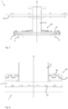
- the Fig. 1a shows a representation of a device according to the prior art.
- a supply line 42 is provided, via which a flowable medium is supplied to a distribution device 4.
- Reference numeral 12 refers to a transport device, which has a rotatable carrier on which the individual containers can also be held.
- Reference numeral 2 denotes a housing within which the containers can be sterilized.
- Fig. 1b shows a detailed view of the Fig. 1a It can be seen here that the distribution device 4 is mounted on the ceiling of the device by means of a rolling bearing 120 with bearing bodies 122. This mounting is relatively complex.
- Fig. 1c shows a further illustration of a device according to the applicant's internal prior art.
- the storage device 120 is shown, which serves to support the distribution device 4.
- a supply line 6 is also provided, which is also arranged vertically here.
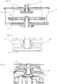
- Fig. 2 shows a schematic representation of a device according to the invention.
- the supply line 6 is provided, which is arranged stationary on a cover 62 of the device.
- Reference numeral 42 again designates the inlet, which here rotates with the distributor device 4.
- Reference numeral 44 designates an outlet.
- the flowable medium is distributed from the inlet 42 via a distribution chamber to the plurality of outlets 44.
- Reference numeral 43 designates a collecting space or chamber, which receives the flowable medium coming from the inlet 42 and distributes it to the individual outlets 44.
- Reference numeral 12 again designates the transport device, and reference numeral 14 designates the carrier on which the containers are held.
- Reference numeral 16 designates a drive shaft by means of which the carrier 14 can be rotated.
- the distribution device 4 is mounted directly and non-rotatably on the support 14 by means of support rods 8. In this way, the distribution device is also supported by this support 14.
- the H2O2 distribution chamber 4 is thus firmly connected to the rotating treatment wheel or transport wheel. This eliminates the need for bearings.
- connection between the stationary roof and the rotating distribution chamber is established via a bellows 22 with a shaft seal.
- the bellows 22 compensates for tolerances, and the shaft seal provides sealing.
- a torque arm prevents the shaft seal from rotating.
- reference numeral 20 denotes a connection point for rotatably “mounting" the inlet 42 relative to the supply line 6.
- reference numeral 22 refers to a bellows, which is a component of this sealing device.
- Reference numeral D denotes an axis of rotation relative to which the distributor device 4 and the carrier 14 are rotatable.
- a lip seal can also be used instead of a bellows 22 with a shaft seal/plain bearing bush.
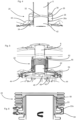
- Fig. 3 shows a more detailed representation of a device according to the invention.
- the vertical supply line 6 and the storage device 20 are also provided here.
- Reference numeral 47 denotes supply lines that carry the sterilization medium to the containers (not shown).
- the containers are preferably attached to the carrier 14 by means of holder devices 32.
- Reference numeral 38 denotes nozzles through which a sterilization agent can exit and sterilize the outside of the preforms.
- Reference numeral 36 denotes an annular channel that can be supplied with the sterilization agent and/or that supplies and/or guides the sterilization agent.
- Reference numeral 34 denotes further application devices, which apply a sterilizing agent to at least the inside of the containers.
- each holder device for a container can be assigned such an application device 34.
- Reference numeral 49 denotes further supply lines, which convey the flowable medium to further application devices 36.
- the application devices 36 serve for the external sterilization of the preforms and are fed from the same H2O2 distribution chamber.
- Reference numeral 61 denotes further lines, which here convey the flowable medium in a vertical direction.
- the distribution device 4 can have switching means (not shown) which enable the supply lines 49 or the supply lines 47 to be selectively supplied with the flowable medium. However, these supply lines 49 and 47 are used simultaneously and are preferably fed from the same distribution chamber.
- a lip seal is used as the sealing device 20.
- This lip seal has a fastening ring 28 to which the actual sealing means 26 is fastened.
- This lip seal 26 has a sealing lip which preferably also allows displacement of the components relative to one another (which can occur, for example, due to thermal expansion or concentricity errors).
- This sealing lip is identified by the reference numeral 26a.
- the main function of the sealing device is to seal the forwarding of the flowable medium.
- this sealing device it is also conceivable for this sealing device to also perform a certain interface function in order to support the rotation of the inlet 42 relative to the feed device.
- the sealing device is preferably not capable of absorbing sufficient forces along the axis of rotation D to hold the distributor device 4 alone.
- the Figs. 5 and 6 show a further embodiment of a device according to the invention, wherein the sealing device is designed as a bellows with a plain bearing bush.
- the bellows 22 is suitable here for compensating for a relative movement of the distributor device or the distributor disk 45 with respect to the upper flange 52. Such relative movements can occur, for example, due to thermal expansion of the housing.
- Reference numeral 54 refers to a clamp which fastens a lower end 22a of the bellows 22 to a holder 53.
- Reference numeral 58 denotes a plain bearing bush, which is designed to be upright here. The entire plain bearing thus functions as a gap seal and guides the bellows 22 in its lower region.
- the clamps 54 and 55 ( Fig.
- Openings 48 for discharging the flowable medium can also be provided in the above-mentioned distributor disc 45. From these openings, the flowable medium reaches the supply lines 49 and thus the annular channel 36.
- the Figures 7 and 8 show a further embodiment of a device according to the invention, in which the seal between the supply line 6 and the distributor device 4 a labyrinth seal 65 is provided.
- the labyrinth seal 65 is preferably formed in two parts, with a first part 66 of the labyrinth seal being arranged on the stationary feed line 6 and a second part 67 of the labyrinth seal being arranged on the rotating distributor device 4.
- the reference numeral 8 again refers to support rods, so that in this embodiment, the distributor device 4 is also arranged on the carrier. In this way, the distributor chamber 4 is also connected to the rotating treatment wheel or transport wheel, thus eliminating the need for bearings.
Landscapes
- Health & Medical Sciences (AREA)
- Public Health (AREA)
- Chemical & Material Sciences (AREA)
- Chemical Kinetics & Catalysis (AREA)
- Epidemiology (AREA)
- Life Sciences & Earth Sciences (AREA)
- Animal Behavior & Ethology (AREA)
- General Chemical & Material Sciences (AREA)
- Veterinary Medicine (AREA)
- General Health & Medical Sciences (AREA)
- Engineering & Computer Science (AREA)
- General Engineering & Computer Science (AREA)
- Mechanical Engineering (AREA)
- Filling Of Jars Or Cans And Processes For Cleaning And Sealing Jars (AREA)
- Branching, Merging, And Special Transfer Between Conveyors (AREA)
- Closures For Containers (AREA)
Claims (14)
- Dispositif (1) de répartition de milieux fluides sur des récipients avec un boîtier (2), avec un système de transport (12) disposé au moins en partie à l'intérieur du boîtier (2) destiné à transporter les récipients, dans lequel ledit système de transport présente un support (14) rotatif, avec un système de répartition (4) disposé à l'intérieur dudit boîtier (2), lequel accueille au moins une entrée (42) pour le milieu fluide et une pluralité de sorties (44), sur lesquelles le milieu fluide peut être réparti, et avec une conduite d'amenée (6), laquelle est adaptée pour et se destine à amener le milieu fluide à l'entrée (42),dans lequel le système de répartition (4) est relié de manière solidaire en rotation au support (14), dans lequel le système d'amenée (6) s'étend à travers une section de couvercle du dispositif (1) et la conduite d'amenée (6) est stationnaire par rapport à la paroi de couvercle et un système d'étanchéification (20) est disposé entre la conduite d'amenée (6) et le système de répartition (4),caractérisé en ce quele système d'étanchéification (20) est également adapté pour et se destine à acheminer du milieu fluide à répartir depuis la conduite d'amenée (6) vers l'entrée.
- Dispositif (1) selon la revendication 1,
caractérisé en ce que
la conduite d'amenée (6) est disposée de manière solidaire en rotation au moins par endroits et le système de répartition (4) peut être tourné par rapport à la conduite d'amenée (6). - Dispositif (1) selon la revendication 1,
caractérisé en ce que
le système de transport fait partie intégrante d'un système de traitement, en particulier d'un système de stérilisation de préformes. - Dispositif (1) selon la revendication 1,
caractérisé en ce que
le milieu fluide est du H2O2 gazeux. - Dispositif (1) selon la revendication 1,
caractérisé en ce que
au moins le dispositif est disposé dans sa totalité dans une salle blanche. - Dispositif (1) selon au moins l'une quelconque des revendications précédentes,
caractérisé en ce que
l'entrée (42) présente une conduite d'entrée (46) disposée de manière solidaire en rotation sur le système de répartition (4), laquelle peut être amenée en communication fluidique avec la conduite d'amenée (6). - Dispositif (1) selon la revendication 6,
caractérisé en ce que
un système d'étanchéification (20) est disposé entre la conduite d'entrée (46) et la conduite d'amenée. - Dispositif (1) selon au moins l'une quelconque des revendications précédentes,
caractérisé en ce que
un système d'étanchéification (20) présente un élément élastique (22) le long de l'axe de rotation (D) et de manière préférée un soufflet. - Dispositif (1) selon la revendication 8,
caractérisé en ce que
l'élément élastique relie la conduite d'amenée (6) à l'entrée (42) du système de répartition (4) et en particulier à une conduite d'entrée (46) de l'entrée. - Dispositif selon au moins l'une quelconque des revendications précédentes,
caractérisé en ce que
le système d'étanchéification (20) présente un système de montage destiné à monter de manière rotative au moins un élément de l'entrée (42) ou de la conduite d'amenée. - Dispositif selon la revendication 7,
caractérisé en ce que
le système de montage (20) et/ou le système d'étanchéification (20) sont réalisés en tant que bagues d'étanchéité d'arbre. - Dispositif selon la revendication 1,
caractérisé en ce que
la conduite d'amenée (6) et le système de répartition (4) sont réalisés sans contact. - Dispositif selon la revendication 12,
caractérisé en ce que
une étanchéification entre la conduite d'amenée (6) et le système de répartition (4) est effectuée par un joint d'étanchéité à labyrinthe (65) sans contact. - Procédé de traitement et en particulier de stérilisation de récipients avec un dispositif (1) selon l'une quelconque des revendications 1 à 13 de répartition de milieux fluides, dans lequel les récipients sont transportés au moyen du système de transport (12) et sont soumis à l'action d'un milieu fluide pendant ledit transport et dans lequel le système de transport (12) présente le support (14) rotatif, au moyen duquel les récipients sont transportés le long d'une trajectoire sensiblement circulaire et ledit support (14) se trouve à l'intérieur du boîtier (2), dans lequel le milieu fluide est amené par l'intermédiaire de l'entrée (42) au système de répartition (4) se trouvant également à l'intérieur du boîtier (2) au moyen de la conduite d'amenée (6) et le système de répartition (4) répartit le milieu fluide sur les sorties (44),
dans lequel le système de répartition (4) est relié de manière solidaire en rotation au support (14) rotatif, dans lequel le système d'amenée (6) s'étend à travers la section de couvercle du dispositif (1) et la conduite d'amenée (6) est stationnaire par rapport à la paroi de couvercle et le système d'étanchéification (20), qui est adapté pour et se destine à acheminer du milieu fluide à répartir depuis la conduite d'amenée (6) vers l'entrée, est disposé entre la conduite d'amenée (6) et le système de répartition (4).
Applications Claiming Priority (2)
| Application Number | Priority Date | Filing Date | Title |
|---|---|---|---|
| DE102016122542.8A DE102016122542A1 (de) | 2016-11-22 | 2016-11-22 | Verteilvorrichtung zum Verteilen von fließfähigen Medien |
| PCT/EP2017/080047 WO2018095970A1 (fr) | 2016-11-22 | 2017-11-22 | Dispositif de répartition pour répartir des substances fluides |
Publications (2)
| Publication Number | Publication Date |
|---|---|
| EP3544924A1 EP3544924A1 (fr) | 2019-10-02 |
| EP3544924B1 true EP3544924B1 (fr) | 2025-04-02 |
Family
ID=60654926
Family Applications (1)
| Application Number | Title | Priority Date | Filing Date |
|---|---|---|---|
| EP17811867.5A Active EP3544924B1 (fr) | 2016-11-22 | 2017-11-22 | Dispositif de répartition pour répartir des substances fluides |
Country Status (5)
| Country | Link |
|---|---|
| US (1) | US11643316B2 (fr) |
| EP (1) | EP3544924B1 (fr) |
| CN (1) | CN110191858B (fr) |
| DE (1) | DE102016122542A1 (fr) |
| WO (1) | WO2018095970A1 (fr) |
Families Citing this family (1)
| Publication number | Priority date | Publication date | Assignee | Title |
|---|---|---|---|---|
| DE102022122632A1 (de) * | 2022-09-06 | 2024-03-07 | Krones Aktiengesellschaft | Vorrichtung und Verfahren zum Umformen von Kunststoffvorformling mit geneigten Anschlüssen an Ringleitungen |
Citations (1)
| Publication number | Priority date | Publication date | Assignee | Title |
|---|---|---|---|---|
| EP2722304A1 (fr) * | 2012-10-17 | 2014-04-23 | Krones AG | Dispositif de remplissage d'au moins un récipient avec un produit de remplissage |
Family Cites Families (13)
| Publication number | Priority date | Publication date | Assignee | Title |
|---|---|---|---|---|
| IT1225360B (it) * | 1988-12-15 | 1990-11-13 | Acma Spa | Apparecchiatura per il riempimento di contenitori |
| DE3927911A1 (de) * | 1989-08-24 | 1991-02-28 | Alfill Getraenketechnik | Verfahren und vorrichtung zum fuellen und verschliessen von dosen |
| DE4304220C2 (de) * | 1993-02-12 | 1997-09-18 | Tetra Laval Holdings & Finance | Verfahren zum Sterilisieren und Füllen von Fließmittelpackungen, Vorrichtung hierfür und Verwendung bei einer besonderen Packung |
| ITBO20010161A1 (it) * | 2001-03-21 | 2002-09-21 | Azionaria Costruzioni Automati | Apparecchiatura per riempire contenitori con materiali, preferibilmente liquidi |
| JP4627190B2 (ja) * | 2005-01-13 | 2011-02-09 | 三菱重工食品包装機械株式会社 | 容器兼用可能な充填ラインの容器搬送システム |
| DE102006053193A1 (de) * | 2006-11-09 | 2008-05-15 | Krones Ag | Vorrichtung und Verfahren zur Herstellung von Kunststoffbehältern |
| DE102007041685A1 (de) * | 2007-09-01 | 2009-03-05 | Krones Ag | Vorrichtung zum Verteilen eines Mediums auf Behältnisse |
| US8621824B2 (en) * | 2009-09-29 | 2014-01-07 | American Sterilizer Company | Bottle decontamination system |
| DE102010031873A1 (de) * | 2010-07-21 | 2012-01-26 | Krones Aktiengesellschaft | Vorrichtung und Verfahren zum Befüllen von Behältnissen mit Reinigungseinrichtung |
| DE102011056440A1 (de) * | 2011-12-14 | 2013-06-20 | Krones Ag | Vorrichtung zum Sterilisieren von Behältnissen mit Ableitungselement für Sterilisationsmittel |
| DE102012109643A1 (de) * | 2012-10-10 | 2014-04-10 | Krones Ag | Vorrichtung zum Behandeln von Behältern und Reinigungsverfahren für eine solche Vorrichtung |
| CN105579347B (zh) * | 2013-09-25 | 2018-03-27 | 费森尤斯卡比德国有限公司 | 用于无菌灌注容器的设备 |
| CN204210791U (zh) * | 2014-10-23 | 2015-03-18 | 广州达意隆包装机械股份有限公司 | 旋转式灌装机的上进料分配器 |
-
2016
- 2016-11-22 DE DE102016122542.8A patent/DE102016122542A1/de active Pending
-
2017
- 2017-11-22 US US16/461,895 patent/US11643316B2/en active Active
- 2017-11-22 WO PCT/EP2017/080047 patent/WO2018095970A1/fr not_active Ceased
- 2017-11-22 EP EP17811867.5A patent/EP3544924B1/fr active Active
- 2017-11-22 CN CN201780072146.9A patent/CN110191858B/zh active Active
Patent Citations (1)
| Publication number | Priority date | Publication date | Assignee | Title |
|---|---|---|---|---|
| EP2722304A1 (fr) * | 2012-10-17 | 2014-04-23 | Krones AG | Dispositif de remplissage d'au moins un récipient avec un produit de remplissage |
Also Published As
| Publication number | Publication date |
|---|---|
| EP3544924A1 (fr) | 2019-10-02 |
| CN110191858B (zh) | 2022-03-29 |
| US11643316B2 (en) | 2023-05-09 |
| US20190330039A1 (en) | 2019-10-31 |
| WO2018095970A1 (fr) | 2018-05-31 |
| CN110191858A (zh) | 2019-08-30 |
| DE102016122542A1 (de) | 2018-05-24 |
Similar Documents
| Publication | Publication Date | Title |
|---|---|---|
| EP1486454B1 (fr) | MACHINE DE TRAITEMENT DE RECIPIENTS ayant UNe enceinte fermée | |
| EP2368835B1 (fr) | Dispositif de traitement de récipients doté d'un isolateur réglable en hauteur | |
| EP2604295B2 (fr) | Procédé de stérilisation de récipients | |
| EP3044156B1 (fr) | Passage tournant et dispositif de traitement et/ou transport de récipients équipé d'un tel passage tournant | |
| EP2030941A1 (fr) | Dispositif de répartition de milieux | |
| EP2489627B1 (fr) | Installation de traitement de récipients dotée d'un passage de mur aseptique | |
| WO2009124885A1 (fr) | Dispositif servant à remplir des récipients | |
| DE102013218337A1 (de) | Transporteinrichtung und Verfahren zum Transport von Kunststoffbehältnissen oder Vorformlingen | |
| DE102005047427B3 (de) | Vorrichtung zum Sterilisieren kontinuierlich hintereinander transportierter Behälter | |
| EP2847123B1 (fr) | Remplisseuse | |
| EP2687236B1 (fr) | Procédé et dispositif de stérilisation de récipients avec prélèvement d'air de refroidissement hors de la chambre stérile | |
| DE102012109643A1 (de) | Vorrichtung zum Behandeln von Behältern und Reinigungsverfahren für eine solche Vorrichtung | |
| EP3544924B1 (fr) | Dispositif de répartition pour répartir des substances fluides | |
| EP0408851B1 (fr) | Dispositif pour stériliser l'extérieur de machines d'embouteillage rotatives | |
| DE102010008366A1 (de) | Medienverteilvorrichtung für Abfüllanlagen | |
| EP2288571B1 (fr) | Machine de traitement de bouteilles ou de contenants similaires | |
| WO2006072403A1 (fr) | Dispositif pour distribuer de facon uniforme un fluide gazeux | |
| DE102018127962B4 (de) | Vorrichtung und Verfahren zur Behandlung von Behältern | |
| EP4606761A1 (fr) | Dispositif de traitement et/ou de transport de récipients | |
| DE102022122086A1 (de) | Vorrichtung und Verfahren zum Transportieren von Behältnissen | |
| DE102023123674A1 (de) | Vorrichtung zum Führen von Behältern, Transportsystem und Behälterbehandlungsmaschine umfassend die Vorrichtung | |
| DE102022132075A1 (de) | Transportvorrichtung und Behälterbehandlungsanlage umfassend die Transportvorrichtung | |
| DE102024110982A1 (de) | Behälterbehandlungsvorrichtung zum Behandeln von Behältern | |
| DE102008059431A1 (de) | Vorrichtung sowie Verfahren zum Behandeln von Flaschen oder dergleichen Behältern | |
| DE102021124863A1 (de) | Verschließvorrichtung zum Verschließen von Behältern |
Legal Events
| Date | Code | Title | Description |
|---|---|---|---|
| STAA | Information on the status of an ep patent application or granted ep patent |
Free format text: STATUS: UNKNOWN |
|
| STAA | Information on the status of an ep patent application or granted ep patent |
Free format text: STATUS: THE INTERNATIONAL PUBLICATION HAS BEEN MADE |
|
| PUAI | Public reference made under article 153(3) epc to a published international application that has entered the european phase |
Free format text: ORIGINAL CODE: 0009012 |
|
| STAA | Information on the status of an ep patent application or granted ep patent |
Free format text: STATUS: REQUEST FOR EXAMINATION WAS MADE |
|
| 17P | Request for examination filed |
Effective date: 20190617 |
|
| AK | Designated contracting states |
Kind code of ref document: A1 Designated state(s): AL AT BE BG CH CY CZ DE DK EE ES FI FR GB GR HR HU IE IS IT LI LT LU LV MC MK MT NL NO PL PT RO RS SE SI SK SM TR |
|
| AX | Request for extension of the european patent |
Extension state: BA ME |
|
| DAV | Request for validation of the european patent (deleted) | ||
| DAX | Request for extension of the european patent (deleted) | ||
| STAA | Information on the status of an ep patent application or granted ep patent |
Free format text: STATUS: EXAMINATION IS IN PROGRESS |
|
| 17Q | First examination report despatched |
Effective date: 20220330 |
|
| GRAP | Despatch of communication of intention to grant a patent |
Free format text: ORIGINAL CODE: EPIDOSNIGR1 |
|
| STAA | Information on the status of an ep patent application or granted ep patent |
Free format text: STATUS: GRANT OF PATENT IS INTENDED |
|
| INTG | Intention to grant announced |
Effective date: 20241029 |
|
| GRAS | Grant fee paid |
Free format text: ORIGINAL CODE: EPIDOSNIGR3 |
|
| P01 | Opt-out of the competence of the unified patent court (upc) registered |
Free format text: CASE NUMBER: APP_2928/2025 Effective date: 20250117 |
|
| GRAA | (expected) grant |
Free format text: ORIGINAL CODE: 0009210 |
|
| STAA | Information on the status of an ep patent application or granted ep patent |
Free format text: STATUS: THE PATENT HAS BEEN GRANTED |
|
| AK | Designated contracting states |
Kind code of ref document: B1 Designated state(s): AL AT BE BG CH CY CZ DE DK EE ES FI FR GB GR HR HU IE IS IT LI LT LU LV MC MK MT NL NO PL PT RO RS SE SI SK SM TR |
|
| REG | Reference to a national code |
Ref country code: GB Ref legal event code: FG4D Free format text: NOT ENGLISH |
|
| REG | Reference to a national code |
Ref country code: CH Ref legal event code: EP |
|
| REG | Reference to a national code |
Ref country code: IE Ref legal event code: FG4D Free format text: LANGUAGE OF EP DOCUMENT: GERMAN |
|
| REG | Reference to a national code |
Ref country code: DE Ref legal event code: R096 Ref document number: 502017016780 Country of ref document: DE |
|
| REG | Reference to a national code |
Ref country code: NL Ref legal event code: MP Effective date: 20250402 |
|
| PG25 | Lapsed in a contracting state [announced via postgrant information from national office to epo] |
Ref country code: NL Free format text: LAPSE BECAUSE OF FAILURE TO SUBMIT A TRANSLATION OF THE DESCRIPTION OR TO PAY THE FEE WITHIN THE PRESCRIBED TIME-LIMIT Effective date: 20250402 |
|
| PG25 | Lapsed in a contracting state [announced via postgrant information from national office to epo] |
Ref country code: ES Free format text: LAPSE BECAUSE OF FAILURE TO SUBMIT A TRANSLATION OF THE DESCRIPTION OR TO PAY THE FEE WITHIN THE PRESCRIBED TIME-LIMIT Effective date: 20250402 Ref country code: PT Free format text: LAPSE BECAUSE OF FAILURE TO SUBMIT A TRANSLATION OF THE DESCRIPTION OR TO PAY THE FEE WITHIN THE PRESCRIBED TIME-LIMIT Effective date: 20250804 Ref country code: FI Free format text: LAPSE BECAUSE OF FAILURE TO SUBMIT A TRANSLATION OF THE DESCRIPTION OR TO PAY THE FEE WITHIN THE PRESCRIBED TIME-LIMIT Effective date: 20250402 |
|
| REG | Reference to a national code |
Ref country code: LT Ref legal event code: MG9D |
|
| PG25 | Lapsed in a contracting state [announced via postgrant information from national office to epo] |
Ref country code: NO Free format text: LAPSE BECAUSE OF FAILURE TO SUBMIT A TRANSLATION OF THE DESCRIPTION OR TO PAY THE FEE WITHIN THE PRESCRIBED TIME-LIMIT Effective date: 20250702 Ref country code: GR Free format text: LAPSE BECAUSE OF FAILURE TO SUBMIT A TRANSLATION OF THE DESCRIPTION OR TO PAY THE FEE WITHIN THE PRESCRIBED TIME-LIMIT Effective date: 20250703 |
|
| PG25 | Lapsed in a contracting state [announced via postgrant information from national office to epo] |
Ref country code: PL Free format text: LAPSE BECAUSE OF FAILURE TO SUBMIT A TRANSLATION OF THE DESCRIPTION OR TO PAY THE FEE WITHIN THE PRESCRIBED TIME-LIMIT Effective date: 20250402 |
|
| PG25 | Lapsed in a contracting state [announced via postgrant information from national office to epo] |
Ref country code: BG Free format text: LAPSE BECAUSE OF FAILURE TO SUBMIT A TRANSLATION OF THE DESCRIPTION OR TO PAY THE FEE WITHIN THE PRESCRIBED TIME-LIMIT Effective date: 20250402 |
|
| PG25 | Lapsed in a contracting state [announced via postgrant information from national office to epo] |
Ref country code: HR Free format text: LAPSE BECAUSE OF FAILURE TO SUBMIT A TRANSLATION OF THE DESCRIPTION OR TO PAY THE FEE WITHIN THE PRESCRIBED TIME-LIMIT Effective date: 20250402 |
|
| PGFP | Annual fee paid to national office [announced via postgrant information from national office to epo] |
Ref country code: FR Payment date: 20250930 Year of fee payment: 9 |
|
| PG25 | Lapsed in a contracting state [announced via postgrant information from national office to epo] |
Ref country code: RS Free format text: LAPSE BECAUSE OF FAILURE TO SUBMIT A TRANSLATION OF THE DESCRIPTION OR TO PAY THE FEE WITHIN THE PRESCRIBED TIME-LIMIT Effective date: 20250702 |
|
| PG25 | Lapsed in a contracting state [announced via postgrant information from national office to epo] |
Ref country code: IS Free format text: LAPSE BECAUSE OF FAILURE TO SUBMIT A TRANSLATION OF THE DESCRIPTION OR TO PAY THE FEE WITHIN THE PRESCRIBED TIME-LIMIT Effective date: 20250802 |
|
| PG25 | Lapsed in a contracting state [announced via postgrant information from national office to epo] |
Ref country code: LV Free format text: LAPSE BECAUSE OF FAILURE TO SUBMIT A TRANSLATION OF THE DESCRIPTION OR TO PAY THE FEE WITHIN THE PRESCRIBED TIME-LIMIT Effective date: 20250402 |
|
| REG | Reference to a national code |
Ref country code: DE Ref legal event code: R097 Ref document number: 502017016780 Country of ref document: DE |
|
| PGFP | Annual fee paid to national office [announced via postgrant information from national office to epo] |
Ref country code: DE Payment date: 20250930 Year of fee payment: 9 |
|
| PG25 | Lapsed in a contracting state [announced via postgrant information from national office to epo] |
Ref country code: SM Free format text: LAPSE BECAUSE OF FAILURE TO SUBMIT A TRANSLATION OF THE DESCRIPTION OR TO PAY THE FEE WITHIN THE PRESCRIBED TIME-LIMIT Effective date: 20250402 Ref country code: DK Free format text: LAPSE BECAUSE OF FAILURE TO SUBMIT A TRANSLATION OF THE DESCRIPTION OR TO PAY THE FEE WITHIN THE PRESCRIBED TIME-LIMIT Effective date: 20250402 |
|
| PGFP | Annual fee paid to national office [announced via postgrant information from national office to epo] |
Ref country code: IT Payment date: 20251022 Year of fee payment: 9 |
|
| PG25 | Lapsed in a contracting state [announced via postgrant information from national office to epo] |
Ref country code: CZ Free format text: LAPSE BECAUSE OF FAILURE TO SUBMIT A TRANSLATION OF THE DESCRIPTION OR TO PAY THE FEE WITHIN THE PRESCRIBED TIME-LIMIT Effective date: 20250402 |
|
| PG25 | Lapsed in a contracting state [announced via postgrant information from national office to epo] |
Ref country code: EE Free format text: LAPSE BECAUSE OF FAILURE TO SUBMIT A TRANSLATION OF THE DESCRIPTION OR TO PAY THE FEE WITHIN THE PRESCRIBED TIME-LIMIT Effective date: 20250402 |
|
| PG25 | Lapsed in a contracting state [announced via postgrant information from national office to epo] |
Ref country code: RO Free format text: LAPSE BECAUSE OF FAILURE TO SUBMIT A TRANSLATION OF THE DESCRIPTION OR TO PAY THE FEE WITHIN THE PRESCRIBED TIME-LIMIT Effective date: 20250402 Ref country code: SK Free format text: LAPSE BECAUSE OF FAILURE TO SUBMIT A TRANSLATION OF THE DESCRIPTION OR TO PAY THE FEE WITHIN THE PRESCRIBED TIME-LIMIT Effective date: 20250402 |
|
| PLBE | No opposition filed within time limit |
Free format text: ORIGINAL CODE: 0009261 |
|
| STAA | Information on the status of an ep patent application or granted ep patent |
Free format text: STATUS: NO OPPOSITION FILED WITHIN TIME LIMIT |
|
| REG | Reference to a national code |
Ref country code: CH Ref legal event code: L10 Free format text: ST27 STATUS EVENT CODE: U-0-0-L10-L00 (AS PROVIDED BY THE NATIONAL OFFICE) Effective date: 20260211 |
|
| 26N | No opposition filed |
Effective date: 20260105 |