EP3545134B1 - Groupe de bourrage pour bourrage des traverses d'une voie ferrée - Google Patents
Groupe de bourrage pour bourrage des traverses d'une voie ferrée Download PDFInfo
- Publication number
- EP3545134B1 EP3545134B1 EP17793570.7A EP17793570A EP3545134B1 EP 3545134 B1 EP3545134 B1 EP 3545134B1 EP 17793570 A EP17793570 A EP 17793570A EP 3545134 B1 EP3545134 B1 EP 3545134B1
- Authority
- EP
- European Patent Office
- Prior art keywords
- tamping
- squeezing
- unit
- cylinders
- pressure chamber
- Prior art date
- Legal status (The legal status is an assumption and is not a legal conclusion. Google has not performed a legal analysis and makes no representation as to the accuracy of the status listed.)
- Active
Links
Images



Classifications
-
- E—FIXED CONSTRUCTIONS
- E01—CONSTRUCTION OF ROADS, RAILWAYS, OR BRIDGES
- E01B—PERMANENT WAY; PERMANENT-WAY TOOLS; MACHINES FOR MAKING RAILWAYS OF ALL KINDS
- E01B27/00—Placing, renewing, working, cleaning, or taking-up the ballast, with or without concurrent work on the track; Devices therefor; Packing sleepers
- E01B27/12—Packing sleepers, with or without concurrent work on the track; Compacting track-carrying ballast
- E01B27/13—Packing sleepers, with or without concurrent work on the track
- E01B27/16—Sleeper-tamping machines
-
- B—PERFORMING OPERATIONS; TRANSPORTING
- B06—GENERATING OR TRANSMITTING MECHANICAL VIBRATIONS IN GENERAL
- B06B—METHODS OR APPARATUS FOR GENERATING OR TRANSMITTING MECHANICAL VIBRATIONS OF INFRASONIC, SONIC, OR ULTRASONIC FREQUENCY, e.g. FOR PERFORMING MECHANICAL WORK IN GENERAL
- B06B1/00—Methods or apparatus for generating mechanical vibrations of infrasonic, sonic, or ultrasonic frequency
- B06B1/18—Methods or apparatus for generating mechanical vibrations of infrasonic, sonic, or ultrasonic frequency wherein the vibrator is actuated by pressure fluid
-
- E—FIXED CONSTRUCTIONS
- E01—CONSTRUCTION OF ROADS, RAILWAYS, OR BRIDGES
- E01B—PERMANENT WAY; PERMANENT-WAY TOOLS; MACHINES FOR MAKING RAILWAYS OF ALL KINDS
- E01B2203/00—Devices for working the railway-superstructure
- E01B2203/12—Tamping devices
Definitions
- the invention relates to a tamping unit for tamping under sleepers of a track, comprising opposing tamping tools which are each connected to an auxiliary cylinder for generating a auxiliary movement, an eccentric drive being provided for generating a vibratory movement.
- Tamping units for tamping under sleepers of a track are already known several times, for example through AT 350 097 B .
- a rotatable eccentric shaft serves as a vibration exciter, to which the auxiliary drives are linked to transmit the vibrations to the tamping tools.
- the advantage of the vibration drive with an eccentric lies in the energy balance of the overall system. Only as much energy is supplied as is taken off at the tamping tine, or what is lost through friction in the system.
- the energy storage at the eccentric takes place in a flywheel or flywheel, which absorbs energy when the tamping ax is braked and returns it to the dynamic system when the tamping ax is accelerated (kinetic energy).
- the GB 797 044 A shows a tamping unit according to the preamble of claim 1.
- the invention is based on the object of an improvement over the prior art for a tamping unit of the type mentioned Specify technique.
- the object of the invention is in particular to create a compact design for tamping units.
- the invention provides that a first auxiliary cylinder is mechanically connected to the eccentric drive and that a first pressure chamber of the first auxiliary cylinder is hydraulically connected to a second pressure chamber of a second auxiliary cylinder via a connecting line in order to transfer a pressure change generated in the first pressure chamber by means of an eccentric drive to the second Transfer pressure chamber.
- the main advantage here is the energy balance of the overall system, because the storage effect of the eccentric drive is used. This combines the advantages of the eccentric drive with the advantage of a compact design because an auxiliary cylinder can be arranged independently of the eccentric drive.
- An advantageous further development of the invention provides that there is an approximately identical force transmission ratio from the respective auxiliary cylinder to the associated tamping tool and that the two auxiliary cylinders are driven in opposite directions.
- each mass has a counter mass that moves in opposite directions.
- the static mass balance achieved in this way minimizes vibrations and noise emissions. This creates a more pleasant working environment for the worker, as well as low-noise use of the tamping unit in residential areas.
- both auxiliary cylinders are aligned approximately horizontally, if the tamping tool assigned to the first auxiliary cylinder has a first mass moment of inertia with respect to a pivot axis, if the tamping tool assigned to the second auxiliary cylinder has a second mass moment of inertia with respect to a pivot axis and if both mass moments of inertia are coordinated with one another. In this way a dynamic mass balancing is ensured, whereby the over a Unit suspension on a tamping machine transmitting vibration is minimized.
- a further advantageous embodiment of the invention is given by the fact that the tamping unit is composed of several individual unit modules to form a multi-sleeper unit. Due to the compactness of the individual aggregate modules, they can be combined cost-effectively to multi-sleeper aggregates. This has a positive effect on both production and maintenance of the individual modules.
- each unit module is advantageously designed to be identical in construction with its own eccentric drive.
- first auxiliary cylinders are mechanically connected to a common eccentric drive and if each first auxiliary cylinder is hydraulically connected to a second auxiliary cylinder.
- a particularly advantageous embodiment provides that the connecting line is connected to a hydraulic system via a pressure screen.
- the adjustment force and vibration of the adjustment cylinders are set via this pressure panel.
- Another useful development is achieved in that an amplitude of an eccentric shaft is distributed uniformly between the two auxiliary cylinders. Instead of controlling one additional cylinder with two individual eccentrics, an eccentric shaft that is twice as large can be used for both additional cylinders.
- FIG. 1 Simplified tamping unit 1 for tamping under a ballast bed 2 below sleepers 3 of a track 4 has pairs of two opposite tamping tools 14, 17 pivotable about a respective pivot axis 5. Specifically, as the respective tamping tool 14, 17, a tamping pick 6 with a pick arm 8 is mounted on a tool carrier 7 and is connected to an auxiliary cylinder 9, 15.
- a first auxiliary cylinder 9 is connected at a cylinder-side end 10 to a vibration drive designed as an eccentric drive 11 with a rotating eccentric shaft 12, and at a piston-side end 13 to a first tamping tool 14.
- a second auxiliary cylinder 15 is rotatably mounted on a rotation axis 16 on the tool carrier 7 and is connected with its piston-side end 13 to a second tamping tool 17.
- the first auxiliary cylinder 9 has a first pressure chamber 18 and a third pressure chamber 19.
- the second auxiliary cylinder 15 has a second pressure chamber 20 and a fourth pressure chamber 21.
- the first pressure chamber 18 of the first auxiliary cylinder 9 is hydraulically connected to the second pressure chamber 20 of the second auxiliary cylinder 15 via a first connecting line 22 in order to transmit part of the vibration generated by the eccentric drive 11 to the second auxiliary cylinder 15.
- the first and second auxiliary cylinders 9, 15 are connected to a constant pressure supply 23 of a hydraulic system.
- the first connecting line 22 is connected to the constant pressure supply 23 and a tank 25 via a servo valve or a proportional valve 24.
- a standby pressure in the first pressure chamber 18 of the first auxiliary cylinder 9 and in the second pressure chamber 20 of the second auxiliary cylinder 15 is thus regulated.
- the auxiliary pressure is superimposed by a pressure generated by means of the eccentric drive oscillating pressure.
- This oscillating pressure is divided between the two auxiliary cylinders 9, 15 via the first connecting line 22.
- Hydraulic fluid oscillates back and forth between the first pressure chamber 18 and the second pressure chamber 20, which also causes a piston rod 29 of the second auxiliary cylinder 15 to vibrate.
- An outflow in the direction of the proportional valve 24 is prevented via a first pressure screen 26.
- the third pressure chamber 19 of the first auxiliary cylinder 9 is hydraulically connected to the fourth pressure chamber 21 of the second auxiliary cylinder 15 via a second connecting line 27. Volume compensation takes place via this second connecting line 27, which is necessary due to the increase in volume in the first and second pressure chambers 18, 20 during a provision process and the superimposed oscillation of the hydraulic fluid.
- the second connecting line 27 is also connected to the constant pressure supply 23 and has a second pressure orifice 28 for pressure regulation. If the piston rods 29 of the auxiliary cylinders 9, 15 are pressed outwards during an ordering process and the stuffing tools 6 are provided, a volume reduction inevitably occurs in the third pressure chamber 19 and in the fourth pressure chamber 21 and the hydraulic fluid is discharged via the second pressure orifice 28.
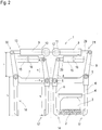
- Fig. 2 shows a further embodiment of the tamping unit 1 for tamping two sleepers 3 of the track 4 at the same time.
- a first unit module 30 and a second unit module 31 are combined to form a two-sleeper tamping unit.
- the tamping tools 14, 17 can be offset from one another in a transverse track direction in order to avoid a mutual collision.
- radii r 1 , r 2 of an upper pivot lever and a lower pivot lever of the first tamping tool 14 and radii r 3 , r 4 of an upper pivot lever and a lower pivot lever of the second tamping tool 17 are defined with respect to the respective pivot axis 5.
- a first mass moment of inertia l1 of the first tamping tool 14 about the assigned pivot axis 5 and a second mass moment of inertia l2 of the second tamping tool 17 about the assigned pivot axis 5 must be observed for a dynamic balance of a single unit module 30, 31 of the tamping unit 1.
- Fig. 3 shows a course of the connecting lines 22, 27 in a combined tamping unit 1 from Fig. 2 .
- a first hydraulic connection line 22 which is connected on the cylinder side to the first auxiliary cylinders 9 and the second auxiliary cylinders 15.
- the second connecting line 27 connects the first auxiliary cylinders 9 to the second auxiliary cylinders 15 on the respective piston side.
- Both first auxiliary cylinders 9 are either connected to a common eccentric drive 11 ( Fig. 4 ) or to its own eccentric drive 11 ( Fig. 2 ) connected.
Landscapes
- Engineering & Computer Science (AREA)
- Architecture (AREA)
- Civil Engineering (AREA)
- Structural Engineering (AREA)
- Mechanical Engineering (AREA)
- Machines For Laying And Maintaining Railways (AREA)
Claims (7)
- Groupe de bourrage (1) pour le bourrage inférieur de traverses (3) d'une voie ferrée (4), comprenant des outils de bourrage opposés (14, 17) qui sont chacun connectés à un cylindre d'adjonction (9, 15) pour la génération d'un mouvement d'adjonction, dans lequel un entraînement excentrique (11) est prévu pour la génération d'un mouvement vibratoire, caractérisé en ce qu'un premier (9) des cylindres d'adjonction (9, 15) est connecté mécaniquement à l'entraînement excentrique (11) et qu'une première chambre de pression (18) du premier cylindre d'adjonction (9) est connectée hydrauliquement à une seconde chambre de pression (20) d'un second (15) des cylindres d'adjonction (9, 15) par le biais d'une conduite de connexion (22, 27) pour transmettre une modification de pression générée dans la première chambre de pression (18) au moyen de l'entraînement excentrique (11) à la seconde chambre de pression (20).
- Groupe de bourrage (1) selon la revendication 1, caractérisé en ce qu'un rapport de transmission de force approximativement identique du cylindre d'adjonction respectif à l'outil de bourrage associé (6) est donné et que les deux cylindres d'adjonction sont commandés de manière diamétralement opposée.
- Groupe de bourrage (1) selon la revendication 1 ou 2, caractérisé en ce que les deux cylindres d'adjonction (9, 15) sont orientés de manière approximativement horizontale, que l'outil de bourrage associé au premier cylindre d'adjonction (9) présente par rapport à un axe de pivotement un premier moment d'inertie, que l'outil de bourrage associé au second cylindre d'adjonction présente par rapport à un axe de pivotement un second moment d'inertie et que les deux moments d'inertie sont accordés l'un à l'autre.
- Groupe de bourrage (1) selon une des revendications 1 à 3, caractérisé en ce que le groupe de bourrage (1) est composé de plusieurs modules de groupe individuels (30, 31) en un groupe à plusieurs traverses.
- Module de bourrage (1) selon la revendication 4, caractérisé en ce que deux premiers cylindres d'adjonction (9) de modules de groupe (30, 31) disposés côte à côte sont connectés mécaniquement à un entraînement excentrique commun (11) et que chaque premier cylindre d'adjonction (9) est connecté hydrauliquement à un second cylindre d'adjonction (15).
- Groupe de bourrage (1) selon une des revendications 1 à 3, caractérisé en ce que la conduite de connexion (22, 27) est raccordée à un système hydraulique par le biais d'un obturateur de pression (26, 28).
- Groupe de bourrage (1) selon une des revendications 1 à 4, caractérisé en ce qu'une amplitude d'un arbre excentrique (12) est répartie en parts égales sur les deux cylindres d'adjonction (9, 15).
Applications Claiming Priority (2)
| Application Number | Priority Date | Filing Date | Title |
|---|---|---|---|
| ATA533/2016A AT519219B1 (de) | 2016-11-25 | 2016-11-25 | Stopfaggregat zum Unterstopfen von Schwellen eines Gleises |
| PCT/EP2017/001266 WO2018095558A1 (fr) | 2016-11-25 | 2017-10-30 | Groupe de bourrage pour bourrage des traverses d'une voie ferrée |
Publications (2)
| Publication Number | Publication Date |
|---|---|
| EP3545134A1 EP3545134A1 (fr) | 2019-10-02 |
| EP3545134B1 true EP3545134B1 (fr) | 2020-09-16 |
Family
ID=60201999
Family Applications (1)
| Application Number | Title | Priority Date | Filing Date |
|---|---|---|---|
| EP17793570.7A Active EP3545134B1 (fr) | 2016-11-25 | 2017-10-30 | Groupe de bourrage pour bourrage des traverses d'une voie ferrée |
Country Status (7)
| Country | Link |
|---|---|
| US (1) | US11053644B2 (fr) |
| EP (1) | EP3545134B1 (fr) |
| CN (1) | CN109983179B (fr) |
| AT (1) | AT519219B1 (fr) |
| EA (1) | EA038406B1 (fr) |
| ES (1) | ES2827829T3 (fr) |
| WO (1) | WO2018095558A1 (fr) |
Cited By (1)
| Publication number | Priority date | Publication date | Assignee | Title |
|---|---|---|---|---|
| EP4403701A1 (fr) * | 2022-12-30 | 2024-07-24 | Plasser & Theurer, Export von Bahnbaumaschinen, Gesellschaft m.b.H. | Unité de bourrage et procédé de bourrage d'un groupe de traverses adjacentes d'une voie ferrée |
Families Citing this family (10)
| Publication number | Priority date | Publication date | Assignee | Title |
|---|---|---|---|---|
| AT518195B1 (de) * | 2016-01-26 | 2017-11-15 | Plasser & Theurer Export Von Bahnbaumaschinen Gmbh | Verfahren zur Verdichtung der Schotterbettung eines Gleises sowie Stopfaggregat |
| AT519219B1 (de) * | 2016-11-25 | 2018-05-15 | Plasser & Theurer Export Von Bahnbaumaschinen Gmbh | Stopfaggregat zum Unterstopfen von Schwellen eines Gleises |
| AT522456B1 (de) * | 2019-10-08 | 2020-11-15 | Plasser & Theurer Export Von Bahnbaumaschinen Gmbh | Stopfaggregat zum Unterstopfen von Schwellen eines Gleises |
| AT523825B1 (de) * | 2020-07-03 | 2021-12-15 | Plasser & Theurer Export Von Bahnbaumaschinen Gmbh | Maschine und Verfahren mit einem Stopfaggregat |
| CN112160199A (zh) * | 2020-10-21 | 2021-01-01 | 中国铁建高新装备股份有限公司 | 捣固装置及捣固车 |
| CN112176791B (zh) * | 2020-10-21 | 2025-05-13 | 中国铁建高新装备股份有限公司 | 一种双枕捣固装置 |
| AT524403B1 (de) * | 2020-10-28 | 2025-04-15 | Hp3 Real Gmbh | Stopfaggregat für eine Gleisstopfmaschine |
| CN113695215B (zh) * | 2021-09-20 | 2022-11-11 | 江西理工大学 | 一种振幅调节装置及方法 |
| AT527577B1 (de) | 2023-11-14 | 2025-04-15 | Plasser & Theurer Export Von Bahnbaumaschinen Gmbh | Stopfaggregat mit kombinierter Schwingungserzeugung |
| AT527798B1 (de) * | 2023-12-05 | 2025-11-15 | Plasser & Theurer Export Von Bahnbaumaschinen Gmbh | Exzenterwellenantrieb von Stopfaggregaten |
Family Cites Families (17)
| Publication number | Priority date | Publication date | Assignee | Title |
|---|---|---|---|---|
| US2587324A (en) * | 1948-10-08 | 1952-02-26 | Hursh | Ballast tamping apparatus |
| GB797044A (en) * | 1954-11-17 | 1958-06-25 | Plasser Bahnbaumasch Franz | Improvements in machines for consolidating the ballast bed under railway sleepers |
| DE1050357B (fr) * | 1955-12-23 | |||
| AT258339B (de) * | 1963-11-29 | 1967-11-27 | Plasser Bahnbaumasch Franz | Hydraulisch betätigbare Einrichtung zur gegenläufigen Verstellung paarweise einander gegenüberliegend angeordneter Werkzeuge von Gleisstopfmaschinen |
| AT339358B (de) * | 1974-05-09 | 1977-10-10 | Plasser Bahnbaumasch Franz | Antriebs- und steuereinrichtung fur vibrier- und verstellbare werkzeuge einer gleisbearbeitungsmaschine, insbesondere fahrbare gleisstopfmaschine |
| CA1051268A (fr) * | 1975-11-17 | 1979-03-27 | Graystone Corporation | Ballastiere et mecanisme vibratoire de commande |
| AT350097B (de) | 1977-02-04 | 1979-05-10 | Plasser Bahnbaumasch Franz | Maschine zum unterstopfen der querschwellen eines gleises |
| AT359110B (de) * | 1977-08-16 | 1980-10-27 | Plasser Bahnbaumasch Franz | Selbstfahrbare gleisbaumaschinenanordnung |
| RU2023784C1 (ru) * | 1991-04-04 | 1994-11-30 | Акционерное общество "Калужский завод путевых машин и гидроприводов" | Гидросистема подбивочного блока шпалоподбивочной машины |
| JP2558439B2 (ja) * | 1994-09-29 | 1996-11-27 | 大淀ヂ−ゼル株式会社 | タンピングユニットの位置決め補助装置 |
| AT500972B1 (de) | 2004-10-29 | 2006-05-15 | Plasser Bahnbaumasch Franz | Verfahren zum unterstopfen von schwellen |
| CN101481895B (zh) * | 2008-01-12 | 2012-05-02 | 襄樊金鹰轨道车辆有限责任公司 | 一种捣固装置 |
| CN101775765B (zh) * | 2010-01-29 | 2012-01-25 | 浙江大学 | 一种液压激振与夹持运动独立的捣固装置 |
| CN102061646B (zh) * | 2010-10-26 | 2012-04-18 | 浙江大学 | 一种捣固装置的液压激振系统 |
| CN102953300B (zh) * | 2011-08-30 | 2015-04-22 | 常州市瑞泰工程机械有限公司 | 正线双枕捣固装置 |
| AT513973B1 (de) * | 2013-02-22 | 2014-09-15 | System7 Railsupport Gmbh | Stopfaggregat für eine Gleisstopfmaschine |
| AT519219B1 (de) * | 2016-11-25 | 2018-05-15 | Plasser & Theurer Export Von Bahnbaumaschinen Gmbh | Stopfaggregat zum Unterstopfen von Schwellen eines Gleises |
-
2016
- 2016-11-25 AT ATA533/2016A patent/AT519219B1/de active
-
2017
- 2017-10-30 CN CN201780072217.5A patent/CN109983179B/zh active Active
- 2017-10-30 EP EP17793570.7A patent/EP3545134B1/fr active Active
- 2017-10-30 WO PCT/EP2017/001266 patent/WO2018095558A1/fr not_active Ceased
- 2017-10-30 ES ES17793570T patent/ES2827829T3/es active Active
- 2017-10-30 US US16/345,007 patent/US11053644B2/en active Active
- 2017-10-30 EA EA201900149A patent/EA038406B1/ru unknown
Non-Patent Citations (1)
| Title |
|---|
| None * |
Cited By (1)
| Publication number | Priority date | Publication date | Assignee | Title |
|---|---|---|---|---|
| EP4403701A1 (fr) * | 2022-12-30 | 2024-07-24 | Plasser & Theurer, Export von Bahnbaumaschinen, Gesellschaft m.b.H. | Unité de bourrage et procédé de bourrage d'un groupe de traverses adjacentes d'une voie ferrée |
Also Published As
| Publication number | Publication date |
|---|---|
| WO2018095558A1 (fr) | 2018-05-31 |
| US20190271119A1 (en) | 2019-09-05 |
| AT519219A4 (de) | 2018-05-15 |
| CN109983179B (zh) | 2021-05-04 |
| CN109983179A (zh) | 2019-07-05 |
| US11053644B2 (en) | 2021-07-06 |
| EA038406B1 (ru) | 2021-08-24 |
| AT519219B1 (de) | 2018-05-15 |
| ES2827829T3 (es) | 2021-05-24 |
| EA201900149A1 (ru) | 2019-10-31 |
| EP3545134A1 (fr) | 2019-10-02 |
Similar Documents
| Publication | Publication Date | Title |
|---|---|---|
| EP3545134B1 (fr) | Groupe de bourrage pour bourrage des traverses d'une voie ferrée | |
| EP3377699B1 (fr) | Groupe de bourrage et procédé de bourrage d'une voie ferrée | |
| DE2211186C3 (de) | Schwingungsdämpfer für Drehflügelflugzeuge | |
| DE2145440A1 (de) | Vorrichtung zur Herstellung von Blöcken | |
| EP0116164B1 (fr) | Appareil de battage par vibration | |
| DE102008021670A1 (de) | Oberflächenbodenverdichter und Verfahren zum Betrieb eines Oberflächenbodenverdichters | |
| DE2928870A1 (de) | Massenkompensiertes stampf- und/oder schlagsystem | |
| DE2547955A1 (de) | Dynamischer absorber und verfahren zum daempfen oder aufheben einer maschinenschwingung | |
| EP0865327B1 (fr) | Dispositif de reglage pour vibrateur a balourd avec couple centrifuge reglable | |
| DE4324595C1 (de) | Schüttelbock | |
| EP3556478B1 (fr) | Entraînement vibratoire doté d'un cylindre multi face | |
| DE10241612B3 (de) | Antriebssystem für ein Kaltpilgerwalzwerk | |
| DE10308094A1 (de) | Vorrichtung und Verfahren zur Prüfung innendruckbelasteter Bauteile | |
| DE69818151T2 (de) | Regelungssystem für hydroelastisches Lager | |
| DE10147046C2 (de) | Antriebssystem für ein Walzwerk | |
| DE2936541A1 (de) | Verfahren zur einstellung der winkelbewegungsgroesse eines schwingsiebs oder einer schwing-aufgabevorrichtung | |
| DE4000011C5 (de) | Vorrichtung zur Schwingungserregung | |
| DE3836746A1 (de) | Verfahren zur aktiven daempfung von schwingungen an einer papiermaschine und vorrichtung zu seiner durchfuehrung | |
| DE102007023963B4 (de) | Vorrichtung für einen Schwingungserreger | |
| DE60117463T2 (de) | Vorrichtungseinheit zur erzeugung einer hin- und hergehenden antriebsbewegung zum antrieb von beweglichen maschinenelementen | |
| WO2014044555A1 (fr) | Mécanisme à secousses et procédé d'activation pneumatique d'un mécanisme à secousses | |
| WO2005056201A1 (fr) | Vibrateur de battage de pieux pour des articles battus | |
| EP1930505A1 (fr) | Compacteur à plaque | |
| DE945548C (de) | Resonanzschwingsieb | |
| DE3872889T2 (de) | Pfahlramme. |
Legal Events
| Date | Code | Title | Description |
|---|---|---|---|
| STAA | Information on the status of an ep patent application or granted ep patent |
Free format text: STATUS: UNKNOWN |
|
| STAA | Information on the status of an ep patent application or granted ep patent |
Free format text: STATUS: THE INTERNATIONAL PUBLICATION HAS BEEN MADE |
|
| PUAI | Public reference made under article 153(3) epc to a published international application that has entered the european phase |
Free format text: ORIGINAL CODE: 0009012 |
|
| STAA | Information on the status of an ep patent application or granted ep patent |
Free format text: STATUS: REQUEST FOR EXAMINATION WAS MADE |
|
| 17P | Request for examination filed |
Effective date: 20190625 |
|
| AK | Designated contracting states |
Kind code of ref document: A1 Designated state(s): AL AT BE BG CH CY CZ DE DK EE ES FI FR GB GR HR HU IE IS IT LI LT LU LV MC MK MT NL NO PL PT RO RS SE SI SK SM TR |
|
| AX | Request for extension of the european patent |
Extension state: BA ME |
|
| DAV | Request for validation of the european patent (deleted) | ||
| DAX | Request for extension of the european patent (deleted) | ||
| GRAP | Despatch of communication of intention to grant a patent |
Free format text: ORIGINAL CODE: EPIDOSNIGR1 |
|
| STAA | Information on the status of an ep patent application or granted ep patent |
Free format text: STATUS: GRANT OF PATENT IS INTENDED |
|
| INTG | Intention to grant announced |
Effective date: 20200506 |
|
| GRAS | Grant fee paid |
Free format text: ORIGINAL CODE: EPIDOSNIGR3 |
|
| GRAA | (expected) grant |
Free format text: ORIGINAL CODE: 0009210 |
|
| STAA | Information on the status of an ep patent application or granted ep patent |
Free format text: STATUS: THE PATENT HAS BEEN GRANTED |
|
| AK | Designated contracting states |
Kind code of ref document: B1 Designated state(s): AL AT BE BG CH CY CZ DE DK EE ES FI FR GB GR HR HU IE IS IT LI LT LU LV MC MK MT NL NO PL PT RO RS SE SI SK SM TR |
|
| REG | Reference to a national code |
Ref country code: GB Ref legal event code: FG4D Free format text: NOT ENGLISH |
|
| REG | Reference to a national code |
Ref country code: CH Ref legal event code: EP |
|
| REG | Reference to a national code |
Ref country code: DE Ref legal event code: R096 Ref document number: 502017007333 Country of ref document: DE |
|
| REG | Reference to a national code |
Ref country code: IE Ref legal event code: FG4D Free format text: LANGUAGE OF EP DOCUMENT: GERMAN |
|
| REG | Reference to a national code |
Ref country code: AT Ref legal event code: REF Ref document number: 1314278 Country of ref document: AT Kind code of ref document: T Effective date: 20201015 |
|
| PG25 | Lapsed in a contracting state [announced via postgrant information from national office to epo] |
Ref country code: GR Free format text: LAPSE BECAUSE OF FAILURE TO SUBMIT A TRANSLATION OF THE DESCRIPTION OR TO PAY THE FEE WITHIN THE PRESCRIBED TIME-LIMIT Effective date: 20201217 Ref country code: FI Free format text: LAPSE BECAUSE OF FAILURE TO SUBMIT A TRANSLATION OF THE DESCRIPTION OR TO PAY THE FEE WITHIN THE PRESCRIBED TIME-LIMIT Effective date: 20200916 Ref country code: NO Free format text: LAPSE BECAUSE OF FAILURE TO SUBMIT A TRANSLATION OF THE DESCRIPTION OR TO PAY THE FEE WITHIN THE PRESCRIBED TIME-LIMIT Effective date: 20201216 Ref country code: HR Free format text: LAPSE BECAUSE OF FAILURE TO SUBMIT A TRANSLATION OF THE DESCRIPTION OR TO PAY THE FEE WITHIN THE PRESCRIBED TIME-LIMIT Effective date: 20200916 Ref country code: SE Free format text: LAPSE BECAUSE OF FAILURE TO SUBMIT A TRANSLATION OF THE DESCRIPTION OR TO PAY THE FEE WITHIN THE PRESCRIBED TIME-LIMIT Effective date: 20200916 Ref country code: BG Free format text: LAPSE BECAUSE OF FAILURE TO SUBMIT A TRANSLATION OF THE DESCRIPTION OR TO PAY THE FEE WITHIN THE PRESCRIBED TIME-LIMIT Effective date: 20201216 |
|
| REG | Reference to a national code |
Ref country code: NL Ref legal event code: MP Effective date: 20200916 |
|
| PG25 | Lapsed in a contracting state [announced via postgrant information from national office to epo] |
Ref country code: LV Free format text: LAPSE BECAUSE OF FAILURE TO SUBMIT A TRANSLATION OF THE DESCRIPTION OR TO PAY THE FEE WITHIN THE PRESCRIBED TIME-LIMIT Effective date: 20200916 Ref country code: RS Free format text: LAPSE BECAUSE OF FAILURE TO SUBMIT A TRANSLATION OF THE DESCRIPTION OR TO PAY THE FEE WITHIN THE PRESCRIBED TIME-LIMIT Effective date: 20200916 |
|
| REG | Reference to a national code |
Ref country code: LT Ref legal event code: MG4D |
|
| PG25 | Lapsed in a contracting state [announced via postgrant information from national office to epo] |
Ref country code: CZ Free format text: LAPSE BECAUSE OF FAILURE TO SUBMIT A TRANSLATION OF THE DESCRIPTION OR TO PAY THE FEE WITHIN THE PRESCRIBED TIME-LIMIT Effective date: 20200916 Ref country code: PT Free format text: LAPSE BECAUSE OF FAILURE TO SUBMIT A TRANSLATION OF THE DESCRIPTION OR TO PAY THE FEE WITHIN THE PRESCRIBED TIME-LIMIT Effective date: 20210118 Ref country code: RO Free format text: LAPSE BECAUSE OF FAILURE TO SUBMIT A TRANSLATION OF THE DESCRIPTION OR TO PAY THE FEE WITHIN THE PRESCRIBED TIME-LIMIT Effective date: 20200916 Ref country code: EE Free format text: LAPSE BECAUSE OF FAILURE TO SUBMIT A TRANSLATION OF THE DESCRIPTION OR TO PAY THE FEE WITHIN THE PRESCRIBED TIME-LIMIT Effective date: 20200916 Ref country code: LT Free format text: LAPSE BECAUSE OF FAILURE TO SUBMIT A TRANSLATION OF THE DESCRIPTION OR TO PAY THE FEE WITHIN THE PRESCRIBED TIME-LIMIT Effective date: 20200916 Ref country code: SM Free format text: LAPSE BECAUSE OF FAILURE TO SUBMIT A TRANSLATION OF THE DESCRIPTION OR TO PAY THE FEE WITHIN THE PRESCRIBED TIME-LIMIT Effective date: 20200916 |
|
| REG | Reference to a national code |
Ref country code: ES Ref legal event code: FG2A Ref document number: 2827829 Country of ref document: ES Kind code of ref document: T3 Effective date: 20210524 |
|
| PG25 | Lapsed in a contracting state [announced via postgrant information from national office to epo] |
Ref country code: PL Free format text: LAPSE BECAUSE OF FAILURE TO SUBMIT A TRANSLATION OF THE DESCRIPTION OR TO PAY THE FEE WITHIN THE PRESCRIBED TIME-LIMIT Effective date: 20200916 Ref country code: IS Free format text: LAPSE BECAUSE OF FAILURE TO SUBMIT A TRANSLATION OF THE DESCRIPTION OR TO PAY THE FEE WITHIN THE PRESCRIBED TIME-LIMIT Effective date: 20210116 Ref country code: AL Free format text: LAPSE BECAUSE OF FAILURE TO SUBMIT A TRANSLATION OF THE DESCRIPTION OR TO PAY THE FEE WITHIN THE PRESCRIBED TIME-LIMIT Effective date: 20200916 |
|
| REG | Reference to a national code |
Ref country code: DE Ref legal event code: R097 Ref document number: 502017007333 Country of ref document: DE |
|
| PG25 | Lapsed in a contracting state [announced via postgrant information from national office to epo] |
Ref country code: LU Free format text: LAPSE BECAUSE OF NON-PAYMENT OF DUE FEES Effective date: 20201030 Ref country code: MC Free format text: LAPSE BECAUSE OF FAILURE TO SUBMIT A TRANSLATION OF THE DESCRIPTION OR TO PAY THE FEE WITHIN THE PRESCRIBED TIME-LIMIT Effective date: 20200916 Ref country code: SK Free format text: LAPSE BECAUSE OF FAILURE TO SUBMIT A TRANSLATION OF THE DESCRIPTION OR TO PAY THE FEE WITHIN THE PRESCRIBED TIME-LIMIT Effective date: 20200916 |
|
| PLBE | No opposition filed within time limit |
Free format text: ORIGINAL CODE: 0009261 |
|
| STAA | Information on the status of an ep patent application or granted ep patent |
Free format text: STATUS: NO OPPOSITION FILED WITHIN TIME LIMIT |
|
| 26N | No opposition filed |
Effective date: 20210617 |
|
| PG25 | Lapsed in a contracting state [announced via postgrant information from national office to epo] |
Ref country code: SI Free format text: LAPSE BECAUSE OF FAILURE TO SUBMIT A TRANSLATION OF THE DESCRIPTION OR TO PAY THE FEE WITHIN THE PRESCRIBED TIME-LIMIT Effective date: 20200916 Ref country code: DK Free format text: LAPSE BECAUSE OF FAILURE TO SUBMIT A TRANSLATION OF THE DESCRIPTION OR TO PAY THE FEE WITHIN THE PRESCRIBED TIME-LIMIT Effective date: 20200916 |
|
| PG25 | Lapsed in a contracting state [announced via postgrant information from national office to epo] |
Ref country code: IE Free format text: LAPSE BECAUSE OF NON-PAYMENT OF DUE FEES Effective date: 20201030 |
|
| PG25 | Lapsed in a contracting state [announced via postgrant information from national office to epo] |
Ref country code: TR Free format text: LAPSE BECAUSE OF FAILURE TO SUBMIT A TRANSLATION OF THE DESCRIPTION OR TO PAY THE FEE WITHIN THE PRESCRIBED TIME-LIMIT Effective date: 20200916 Ref country code: MT Free format text: LAPSE BECAUSE OF FAILURE TO SUBMIT A TRANSLATION OF THE DESCRIPTION OR TO PAY THE FEE WITHIN THE PRESCRIBED TIME-LIMIT Effective date: 20200916 Ref country code: CY Free format text: LAPSE BECAUSE OF FAILURE TO SUBMIT A TRANSLATION OF THE DESCRIPTION OR TO PAY THE FEE WITHIN THE PRESCRIBED TIME-LIMIT Effective date: 20200916 |
|
| PG25 | Lapsed in a contracting state [announced via postgrant information from national office to epo] |
Ref country code: MK Free format text: LAPSE BECAUSE OF FAILURE TO SUBMIT A TRANSLATION OF THE DESCRIPTION OR TO PAY THE FEE WITHIN THE PRESCRIBED TIME-LIMIT Effective date: 20200916 |
|
| PG25 | Lapsed in a contracting state [announced via postgrant information from national office to epo] |
Ref country code: NL Free format text: LAPSE BECAUSE OF NON-PAYMENT OF DUE FEES Effective date: 20200923 |
|
| P01 | Opt-out of the competence of the unified patent court (upc) registered |
Effective date: 20230528 |
|
| PGFP | Annual fee paid to national office [announced via postgrant information from national office to epo] |
Ref country code: BE Payment date: 20250922 Year of fee payment: 9 Ref country code: GB Payment date: 20250808 Year of fee payment: 9 |
|
| REG | Reference to a national code |
Ref country code: CH Ref legal event code: U11 Free format text: ST27 STATUS EVENT CODE: U-0-0-U10-U11 (AS PROVIDED BY THE NATIONAL OFFICE) Effective date: 20251101 |
|
| PGFP | Annual fee paid to national office [announced via postgrant information from national office to epo] |
Ref country code: AT Payment date: 20250905 Year of fee payment: 9 |
|
| PGFP | Annual fee paid to national office [announced via postgrant information from national office to epo] |
Ref country code: IT Payment date: 20251031 Year of fee payment: 9 |
|
| PGFP | Annual fee paid to national office [announced via postgrant information from national office to epo] |
Ref country code: FR Payment date: 20251024 Year of fee payment: 9 |
|
| PGFP | Annual fee paid to national office [announced via postgrant information from national office to epo] |
Ref country code: CH Payment date: 20251101 Year of fee payment: 9 |
|
| PGFP | Annual fee paid to national office [announced via postgrant information from national office to epo] |
Ref country code: ES Payment date: 20251118 Year of fee payment: 9 |
|
| PGFP | Annual fee paid to national office [announced via postgrant information from national office to epo] |
Ref country code: DE Payment date: 20251217 Year of fee payment: 9 |