EP3545143B1 - Drain pour dispositif de recyclage d'eau - Google Patents
Drain pour dispositif de recyclage d'eau Download PDFInfo
- Publication number
- EP3545143B1 EP3545143B1 EP17874619.4A EP17874619A EP3545143B1 EP 3545143 B1 EP3545143 B1 EP 3545143B1 EP 17874619 A EP17874619 A EP 17874619A EP 3545143 B1 EP3545143 B1 EP 3545143B1
- Authority
- EP
- European Patent Office
- Prior art keywords
- water
- buffer
- drain
- outlet
- recycling
- Prior art date
- Legal status (The legal status is an assumption and is not a legal conclusion. Google has not performed a legal analysis and makes no representation as to the accuracy of the status listed.)
- Active
Links
Images


Classifications
-
- E—FIXED CONSTRUCTIONS
- E03—WATER SUPPLY; SEWERAGE
- E03B—INSTALLATIONS OR METHODS FOR OBTAINING, COLLECTING, OR DISTRIBUTING WATER
- E03B1/00—Methods or layout of installations for water supply
- E03B1/04—Methods or layout of installations for water supply for domestic or like local supply
- E03B1/041—Greywater supply systems
-
- A—HUMAN NECESSITIES
- A47—FURNITURE; DOMESTIC ARTICLES OR APPLIANCES; COFFEE MILLS; SPICE MILLS; SUCTION CLEANERS IN GENERAL
- A47K—SANITARY EQUIPMENT; ACCESSORIES THEREFOR, e.g. TOILET ACCESSORIES
- A47K3/00—Baths; Showers; Appurtenances therefor
- A47K3/28—Showers or bathing douches
-
- E—FIXED CONSTRUCTIONS
- E03—WATER SUPPLY; SEWERAGE
- E03B—INSTALLATIONS OR METHODS FOR OBTAINING, COLLECTING, OR DISTRIBUTING WATER
- E03B1/00—Methods or layout of installations for water supply
- E03B1/04—Methods or layout of installations for water supply for domestic or like local supply
- E03B1/041—Greywater supply systems
- E03B1/042—Details thereof, e.g. valves or pumps
-
- B—PERFORMING OPERATIONS; TRANSPORTING
- B01—PHYSICAL OR CHEMICAL PROCESSES OR APPARATUS IN GENERAL
- B01D—SEPARATION
- B01D2239/00—Aspects relating to filtering material for liquid or gaseous fluids
- B01D2239/02—Types of fibres, filaments or particles, self-supporting or supported materials
- B01D2239/025—Types of fibres, filaments or particles, self-supporting or supported materials comprising nanofibres
-
- B—PERFORMING OPERATIONS; TRANSPORTING
- B01—PHYSICAL OR CHEMICAL PROCESSES OR APPARATUS IN GENERAL
- B01D—SEPARATION
- B01D39/00—Filtering material for liquid or gaseous fluids
- B01D39/14—Other self-supporting filtering material ; Other filtering material
- B01D39/20—Other self-supporting filtering material ; Other filtering material of inorganic material, e.g. asbestos paper, metallic filtering material of non-woven wires
- B01D39/2068—Other inorganic materials, e.g. ceramics
- B01D39/2082—Other inorganic materials, e.g. ceramics the material being filamentary or fibrous
-
- E—FIXED CONSTRUCTIONS
- E03—WATER SUPPLY; SEWERAGE
- E03B—INSTALLATIONS OR METHODS FOR OBTAINING, COLLECTING, OR DISTRIBUTING WATER
- E03B1/00—Methods or layout of installations for water supply
- E03B1/04—Methods or layout of installations for water supply for domestic or like local supply
- E03B1/041—Greywater supply systems
- E03B2001/045—Greywater supply systems using household water
-
- E—FIXED CONSTRUCTIONS
- E03—WATER SUPPLY; SEWERAGE
- E03C—DOMESTIC PLUMBING INSTALLATIONS FOR FRESH WATER OR WASTE WATER; SINKS
- E03C1/00—Domestic plumbing installations for fresh water or waste water; Sinks
- E03C1/12—Plumbing installations for waste water; Basins or fountains connected thereto; Sinks
- E03C1/22—Outlet devices mounted in basins, baths, or sinks
-
- E—FIXED CONSTRUCTIONS
- E03—WATER SUPPLY; SEWERAGE
- E03F—SEWERS; CESSPOOLS
- E03F5/00—Sewerage structures
- E03F5/04—Gullies inlets, road sinks, floor drains with or without odour seals or sediment traps
- E03F5/0407—Floor drains for indoor use
- E03F5/0408—Floor drains for indoor use specially adapted for showers
Definitions
- the apparatuses and methods described herein generally relates to water recycling. More particularly, a drain for a water recycling device is presented.
- a water recycling device An important part of a water recycling device is the drain collecting the used water to be recycled.
- a drain must be capable of directing water to the water recycling device while conforming to a number of requirements set out for conventional drains used to collect water.
- the drain must also be able to reliably provide water to the water recycling device.
- drain arrangements in a water recycling apparatuses are known from e.g. DE4124605 and US patent application No. 12/996,385 .
- US 2011/146800 there is disclosed a domestic water recycling system using a combination of an optical detector to detect certain smaller sized (non-filtered) contaminants and a filter to remove larger sized (filtered) contaminants. Furthermore, in US 5,293,654 there is disclosed a shower assembly having a spray nozzle through which liquid flows into a shower cabinet. In DE19741827 there is disclosed a bath drain fitting. In the device, a siphon forms an odor trap. Neither of the documents above presents a drain arrangement such as according to the present invention, which is further described below.
- a drain for a water recycling device comprising a drain inlet configured to receive used water from an outlet of the water recycling device; a water buffer configured to hold a volume of water, wherein the water buffer comprises an outer wall element and a bottom surface; a recycling pipe comprising an recycling pipe intake, the recycling pipe intake comprising an open end, wherein the recycling pipe and the recycling pipe intake are configured to receive used water to be recycled from the water buffer; and a buffer outlet configured to output water from the water buffer.
- the drain comprises a number of angled flaps arranged in the water buffer such that water received by the water buffer via the drain inlet is set in a circular motion in the water buffer.
- the drain may comprise a diverter configured to divert the used water to the water buffer, and to prevent the used water from entering the buffer outlet without passing the water buffer.
- the diverter may comprise a surface arranged above the buffer outlet with respect to gravity when the drain is in use.
- the surface may be arranged such that a projection of the surface along a direction of gravity when the drain is in use at least partially covers the buffer outlet.
- the surface may be arranged to extend at least partially in a direction of gravity when the drain is in use such that water on the surface is directed towards the water buffer.
- the open end of the recycling pipe intake may be directed towards the bottom surface of the water buffer.
- An upper end of the open end of the recycling pipe intake may be arranged in line with or below an upper end of the outer wall element with respect to gravity when the drain is in use.
- the outer wall element and/or the bottom surface may be arranged to form a barrier preventing the volume of water from entering the buffer outlet.
- the water buffer further may comprise an inner wall element, wherein the outer wall element and/or the bottom surface and/or the inner wall element are arranged to form a barrier preventing the volume of water from entering the buffer outlet.
- An upper end of the open end of the recycling pipe may be arranged in line with or below an upper end of the inner wall element with respect to gravity when the drain is in use.
- the water buffer may have a circular cross section when viewed along the direction of gravity when the drain is in use.
- the recycling pipe intake may at least partially enclose the buffer outlet.
- the water buffer may comprise a draining channel configured to allow a flow of water from the water buffer to the buffer outlet.
- the recycling pipe intake may comprise a pre-filter.
- the drain may comprise a sensor arrangement configured to measure a water quality parameter in water in the water buffer.
- a water recycling device comprising an outlet configured to output treated water; a drain according to first aspect of the invention for collecting used water output from the outlet; a drain discard path arranged downstream of the drain; a recirculation loop in liquid communication with the drain and the outlet, the recirculation loop comprising a water treatment arrangement for treating the used water; and a circulation pump for providing a flow in the water recycling device.
- the water recycling device may be a shower.
- a method for collecting water to be recycled in a drain of a water recycling device comprising: a drain inlet configured to receive used water from an outlet of the water recycling device; a water buffer configured to hold a volume of water, wherein the water buffer comprises an outer wall element and a bottom surface; a recycling pipe comprising an recycling pipe intake, wherein the recycling pipe is configured to receive used water to be recycled from the water buffer; and a buffer outlet; the drain being characterized in that it comprises a number of angled flaps arranged in the water buffer such that water received by the water buffer via the drain inlet is set in a circular motion in the water buffer; wherein the method comprises the steps of: collecting the used water in the water buffer; determining a water quality measure of the collected water; if the water quality measure of the collected water is above a quality threshold, feeding the collected water via the recycling pipe to the water recycling device; if the water quality measure of the collected water
- the present disclosure describes a drain for a water recycling device. Initially, some terminology may be defined to provide clarification for the following disclosure.
- 'drain' referred to in the present disclosure is not to be given the conventional meaning of a drain; a conventional drain is a fixture for that provides an exit-point for waste water.
- the term 'drain' may be exchanged for a collecting arrangement, a sensor tank, a recirculation tank, or a floor unit.
- the term 'drain' implies a point leading to a e.g. a sewage, but wherein the drain does in fact not form part of the sewage itself.
- the water buffer may act as an interface between the recycling pipe and a drain discard path arranged downstream of the drain.
- a water recycling device may receive used water to be treated and recycled. Used water may thus pass a water treatment arrangement of the water recycling device, after which the used water may be referred to as treated water. Treated water leaving an output of the water recycling device may be referred to as used water. In other words, the moment treated water is emitted from the output of the water recycling device, it may be referred to as used water.
- a drain wherein used water is held in a water buffer may allow for the used water to be analyzed with respect to water quality parameters before used water is drawn into a recirculation loop of the water recycling device.
- the water buffer holds a volume of water such that a recycling pump of the water recycling device can reliably draw water into the water recycling device.
- the water recycling device 100 comprises an outlet 102 configured to output treated water, a drain 104 for collecting used water output from said outlet, a recirculation loop 108 in liquid communication with the drain 104 and the outlet 102, a valve arrangement 109, an external water path 111 in liquid communication with the valve arrangement 108, a circulation pump 110 for providing a flow in the water recycling device, and a water treatment arrangement 112.
- the external water path 111 may provide external water to the recirculation loop 108.
- the water treatment arrangement 112 may comprise a filter arrangement and/or a UV light treatment arrangement.
- the water treatment arrangement 112 may comprise at least one filter, such as a nanofilter, a microfilter, or a nanofilter and a microfilter.
- the water treatment arrangement 112 may comprise at least one particle filter and at least one microbiological filter.
- the water treatment arrangement 112 may comprise at least one active substance for reducing harmful effects of microorganisms in water passing the water treatment arrangement 112. Such an active substance may for example be contained within a filter media of the filter, and/or be released to the water inside the water treatment arrangement 112.
- the water recycling device may be a shower.
- the drain according to the present disclosure can be implemented in a wide variety of water recycling devices without departing from the scope of the present inventive concept.
- the drain 200 comprises a drain inlet 214 configured to receive used water from an outlet of the water recycling device.
- the used water may flow through the drain inlet 214 via a grating 213.
- the drain 200 further comprises a water buffer 216.
- the water buffer 216 may be arranged below the drain inlet 214 with respect to gravity when the drain 200 is in use.
- the water buffer 216 is configured to hold a volume of water, wherein the water may be for example used water.
- the water buffer 216 comprises an outer wall element 220 and a bottom surface 222.
- the drain 200 further comprises a recycling pipe 224 comprising a recycling pipe intake 226, the recycling pipe intake 226 comprising an open end 228.
- the recycling pipe intake 226 may be in liquid communication with the recirculation loop of the water recycling device.
- the recycling pipe intake 226 may comprise a pre-filter.
- the pre-filter may be a mesh filter.
- the pre-filter may be arranged in the open end 228.
- the pre-filter may provide for that particles in the used water are removed before the used water enters the recycling pipe 224 and the water recycling device.
- the recycling pipe 224 and recycling pipe intake 226 are configured to receive used water to be recycled from the water buffer.
- the recycling pipe 224 and recycling pipe intake 226 may also be configured to output water into the water buffer 216. Consequently, the water buffer 216 is configured to hold a volume of water, wherein the water may be for example treated water and/or external water from an external water path connected to the recirculation loop of the water recycling device.
- An advantage with this arrangement is that the pre-filter of the recycling pipe intake 226 may be flushed. This may prevent particles from clogging the pre-filter.
- the pre-filter of the recycling pipe intake 226 may be backflushed. Thus, e.g. dirt, hair and the like which is flushed away from the pre-filter may be directed via the buffer outlet 229 and a drain discard path 218 to be removed from the water recycling device.
- a volume of water in the water buffer 216 may be replaced with external water.
- particles on the bottom surface 222 of the water buffer 216 may be removed from the water buffer 216 as a result of a flow of water entering the water buffer 216 from the recycling pipe 224.
- the drain 200 further comprises a buffer outlet 229.
- the buffer outlet 229 may be configured to allow a flow of water from the water buffer 216 to a drain discard path 218.
- a water trap 232 may be arranged between the buffer outlet 229 and the drain discard path 218. Water entering the drain discard path 218 may be removed from the water recycling device.
- the buffer outlet 229 may be arranged substantially in a center of the water buffer 216.
- the drain 200 may comprise a diverter 230.
- the diverter 230 may be configured to divert the used water received via the drain inlet 214 to the water buffer 216.
- the diverter 230 may be configured to prevent the used water from entering the buffer outlet 229 without passing the water buffer 216.
- the diverter 230 may comprise a surface arranged above the buffer outlet 229 with respect to gravity when the drain 200 is in use.
- the surface of the diverter 230 may be arranged such that a projection of the surface along a direction of gravity when the drain is in use at least partially covers the buffer outlet. In other words, the surface of the diverter 230 may be arranged such that water received via the drain inlet 214 is prevented from flowing directly into the buffer outlet 229.
- the surface of the diverter 230 may be arranged to extend at least partially in a direction of gravity when the drain 200 is in use such that water present on the surface is directed towards the water buffer 216. In other words, the surface of the diverter 230 may be arranged at an angle with respect to a direction of gravity when the drain 200 is in use, wherein the angle is not 90 degrees.
- the diverter may form part of the recycling pipe 224 and/or the recycling pipe intake 226.
- the drain 200 may comprise a sensor arrangement configured to measure a water quality parameter in water in the water buffer 216.
- the sensor arrangement may be configured to determine a water quality measure of water.
- the sensor arrangement may be placed in the water buffer 216.
- the sensor arrangement may comprise an electrical conductivity sensor.
- the sensor arrangement may be configured to determine a temperature of water in the water buffer 216.
- the drain 200 may comprise a water level sensor arrangement configured to determine a level of water in the water buffer 216.
- the outer wall element 220 and/or the bottom surface 222 may be arranged to form a barrier preventing the volume of water held by the water buffer 216 from entering the buffer outlet 229. Consequently, a buffer of used water may be created in the water buffer 216. If the buffer of used water is to be recycled in the water recycling device, a recirculation pump may draw the used water in the water buffer 216 into the water recycling device via the recycling pipe intake 226 and recycling pipe 224. On the other hand, if the buffer of used water is not to be recycled, used water received via the drain inlet 214 may be allowed to fill the water buffer 216 until a water level overcomes the barrier, such that used water is directed via the buffer outlet 229 to the drain discard path 218.
- the recycling pipe intake 226 may be arranged below the buffer outlet 229 with respect to gravity when the drain is in use.
- the buffer outlet does not necessarily need to be equipped with a valve in order to restrict a flow of water from the water buffer 216 to the drain discard path 218, and to allow water to fill the water buffer 216 such that water can be drawn into the recycling pipe 224.
- the recycling pipe 224 may form part of the barrier preventing the volume of water held by the water buffer 216 from entering the buffer outlet 229.
- the recycling pipe intake 226 may form part of the barrier preventing the volume of water held by the water buffer 216 from entering the buffer outlet 229.
- used water may be prevented from being recycled into the water recycling device when the recycling pipe 224 is not installed in the drain 200.
- This arrangement may also be advantageous in a scenario where the recycling pipe intake 226 comprises a pre-filter as described above, since the barrier preventing the volume of water held by the water buffer 216 from entering the buffer outlet 229 is formed only when the recycling pipe intake 226, and thus the pre-filter, is installed correctly.
- Surfaces of the drain 200 intended to be in direct contact with water may comprise mechanical and/or chemical properties such that dirt and/or microorganisms are less likely to attach to the surfaces.
- the recycling pipe 224 may be connected to the water recycling device via a detachable connection.
- the detachable connection may be sealed with an o-ring.
- the water buffer 216 may comprise a draining channel (not shown).
- the draining channel may be arranged on the bottom surface 222, and/or on the outer wall element 220, and/or on an inner wall element as described below.
- the draining channel may be arranged near a bottom of the water buffer 216, such that water in the water buffer 216 can be drained from the water buffer 216 via the buffer outlet 229.
- the draining channel may be in liquid communication with the buffer outlet 219.
- the draining channel may have a draining channel area providing for a flow of water out from the water buffer 216.
- the draining channel area may be adjusted to allow a flow rate similar to or lower than a flow rate of water flowing into the water buffer 216 via the drain inlet 214.
- the draining channel may provide for that the water buffer 216 can be completely emptied. By emptying the water buffer 216, a risk of microbiological growth may be decreased. More specifically, a risk of microbiological growth in the water buffer 216 may be decreased
- the open end 228 of the recycling pipe intake 226 may be directed towards the bottom surface of the water buffer 216.
- air may be prevented from entering the recycling pipe intake 226.
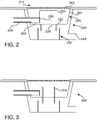
- the drain 300 may comprise any of the features described in conjunction with FIG. 2 .
- the drain 300 may further comprise an inner wall element 334.
- the inner wall element 334 and/or the outer wall element and/or the bottom surface may be arranged to form a barrier preventing the volume of water held by the water buffer from entering the buffer outlet.
- the inner wall element 334 may extend downwards into a water trap, such that the inner wall element 334 forms a part of the water trap.
- the drain 400 may comprise any of the features described in conjunction with FIG. 2 and FIG. 3 .
- the drain 400 comprises an outer wall element, wherein the buffer outlet 429 is arranged at the outer edge of the water buffer.
- used water held by the water buffer may rise to a water level above the outer wall element, such that the used water held by the water buffer is directed to a drain discard path arranged below the water buffer.
- a drain wherein the recycling pipe is arranged inside the water buffer has been disclosed.
- a water trap may be arranged below the water buffer.
- the recycling pipe may be arranged in the water trap. Used water may thus be drawn from the water trap into the water recycling device.
- the water trap may be referred to as a water buffer.
- FIG. 5 a top view of a drain for a water recycling device is illustrated.
- the recycling pipe 524 extends into the water buffer 516.
- the water buffer 516 may have a circular cross section when viewed along the direction of gravity when the drain is in use. However, different shaped cross sections of the water buffer 516 are also possible, such as rectangular cross sections, or any other cross section having a geometrical shape of a polygon.
- the recycling pipe 524 may extend at least to the edge of the buffer outlet 529.
- the recycling pipe 524 may extend at least to an opposite edge of the water buffer 516 with respect to an entry point of the recycling pipe 524 in the water buffer 516 and the outer wall element 520.
- the recycling pipe 524 may extend a length of the bottom surface 522.
- a top view of the buffer outlet 529 may be circular as shown in FIG. 5 .
- a top view of the buffer outlet 529 may be in the shape of a semi-circle, a square, or any other geometrical shape.
- a top view of the recycling pipe intake 526 may be in the shape of a circle, a ring, a semi-circle, a square, or any other geometrical shape.
- the diverter 630 may comprise a surface arranged above the buffer outlet (not shown) of the water buffer 616.
- the surface may be arranged such that a projection of the surface along a direction of gravity when the drain is in use at least partially covers the buffer outlet (not shown). In this illustration, a direction of gravity is pointing inwards into the illustration.
- FIG. 7 a top view of an alternative recycling pipe intake 726 is illustrated.
- the recycling pipe intake 726 encloses the buffer outlet 729.
- the recycling pipe intake 726 may at least partially enclose the buffer outlet 729. This arrangement may provide for that an area of the pre-filter of the recycling pipe intake 726 is increased.
- the recycling pipe intake 826 may comprise a number of open ends 828.
- the recycling pipe intake 826 may have an annular cross section.
- the number of open ends 828 may be larger at a proximal end 838 of the recycle pipe intake 826 compared to a distal end 836 of the recycling pipe intake 826.
- the number of open ends 828 may become increasingly larger from the distal end 836 to the proximal end 838.
- collected water in the water buffer may be drawn into the recycling pipe via the recycling pipe intake 826 at different flow rates with respect to a location of the number of open ends 828. Consequently, a circular flow of water in the water buffer as described below may be facilitated.
- the number of open ends 828 may provide for that a vortex of water is formed in the water buffer.
- the water buffer comprises a number of angled flaps such that water entering the water buffer via the drain inlet is set in a circular motion in the water buffer.
- water entering the water buffer via the drain inlet may be diverted by the number of angled flaps in a direction such that a circular flow is created in the water buffer.
- water in the water buffer may be directed towards an outer edge of the water buffer and/or towards the outer wall element of the water buffer.
- Such a circular flow of water may be referred to as a vortex.
- water in the water buffer may be prevented from entering the buffer outlet arranged in a center of the water buffer. This effect may be facilitated by drawing water from the water buffer into the water recycling device via the recycling pipe intake.
- An advantage of this arrangement is that a water quality measure of water in the water buffer may be detected by the sensor arrangement before water is allowed to enter the buffer outlet.
- the number of angled flaps is arranged in the water buffer.
- the method comprises the step 940 of collecting used water in a water buffer; the step 942 of determining a water quality measure of the collected water; the step 944 of, if the water quality measure of the collected water is above a quality threshold, feeding at least a portion of the collected water via the recycling pipe to the water recycling device; and the step 946 of, if the water quality measure of the collected water is below a quality threshold, allowing at least a portion of the collected water to flow via the buffer outlet to a drain discard path of the water recycling device.
Landscapes
- Health & Medical Sciences (AREA)
- Public Health (AREA)
- Life Sciences & Earth Sciences (AREA)
- Engineering & Computer Science (AREA)
- Hydrology & Water Resources (AREA)
- Water Supply & Treatment (AREA)
- Epidemiology (AREA)
- General Health & Medical Sciences (AREA)
- Farming Of Fish And Shellfish (AREA)
- Filtration Of Liquid (AREA)
- Sink And Installation For Waste Water (AREA)
Claims (10)
- Drain (104) destiné à un dispositif de recyclage d'eau (100), ledit drain (104) comprenantune entrée de drain (214) conçue pour recevoir de l'eau usée provenant d'une sortie (102) dudit dispositif de recyclage d'eau (100) ;un tampon d'eau (216) conçu pour contenir un volume d'eau, ledit tampon d'eau (216) comprenant un élément de paroi externe (220) et une surface inférieure (222) ;un tuyau de recyclage (224) comprenant une entrée de tuyau de recyclage (226), ladite entrée de tuyau de recyclage (226) comprenant une extrémité ouverte (228), ledit tuyau de recyclage (224) et ladite entrée de tuyau de recyclage (226) étant conçus pour recevoir de l'eau usée à recycler provenant dudit tampon d'eau (216) ; etune sortie de tampon (229) conçue pour évacuer l'eau dudit tampon d'eau (216),ledit drain (104) étant caractérisé en ce qu'il comprend en outre un certain nombre de clapets angulaires disposés dans ledit tampon d'eau (216) de sorte que l'eau reçue par ledit tampon d'eau (216) par l'intermédiaire de ladite entrée de drain (214) soit placée dans un mouvement circulaire dans ledit tampon d'eau (216).
- Drain (104) selon la revendication 1, comprenant en outre un partiteur (230) conçu pour dévier ladite eau usée vers ledit tampon d'eau (216), et pour empêcher ladite eau usée d'entrer dans ladite sortie de tampon (229) sans passer par ledit tampon d'eau (216).
- Drain (104) selon l'une quelconque des revendications précédentes, ladite extrémité ouverte (228) de ladite entrée de tuyau de recyclage (226) étant dirigée vers ladite surface inférieure (222) dudit tampon d'eau (216).
- Drain (104) selon l'une quelconque des revendications précédentes, ledit tampon d'eau (216) comprenant en outre un élément de paroi interne (334), ledit élément de paroi externe (220) et/ou ladite surface inférieure (222) et/ou ledit élément de paroi interne (334) étant conçus pour former une barrière empêchant ledit volume d'eau d'entrer dans ladite sortie de tampon (229) .
- Drain (104) selon l'une quelconque des revendications précédentes, ladite entrée de tuyau de recyclage (226) enfermant au moins partiellement ladite sortie de tampon (229).
- Drain (104) selon l'une quelconque des revendications précédentes, ledit tampon d'eau (216) comprenant un canal de drainage conçu pour permettre un écoulement d'eau dudit tampon d'eau (216) à ladite sortie de tampon (229).
- Drain (104) selon l'une quelconque des revendications précédentes, ladite entrée de tuyau de recyclage (226) comprenant un pré-filtre.
- Dispositif de recyclage d'eau (100) comprenantune sortie (102) conçue pour évacuer l'eau traitée ;un drain (104) selon l'une quelconque des revendications 1 à 7 pour collecter l'eau usée sortant de ladite sortie (102) ;un trajet de rejet de drain (106) disposé en aval dudit drain (104) ;une boucle de recirculation (108) en communication liquide avec ledit drain (104) et ladite sortie (102), ladite boucle de recirculation (108) comprenant un dispositif de traitement de l'eau (112) pour traiter ladite eau usée ; etune pompe de circulation (110) pour produire un flux dans ledit dispositif de recyclage d'eau (100).
- Dispositif de recyclage d'eau (100) selon la revendication 8, ledit dispositif de recyclage d'eau (100) étant une douche.
- Procédé pour collecter l'eau à recycler dans un drain (104) d'un dispositif de recyclage d'eau (100), ledit drain (104) comprenant :une entrée de drain (214) conçue pour recevoir de l'eau usée provenant d'une sortie (102) dudit dispositif de recyclage d'eau (100) ;un tampon d'eau (216) conçu pour contenir un volume d'eau, ledit tampon d'eau (216) comprenant un élément de paroi externe (220) et une surface inférieure (222) ;un tuyau de recyclage (224) comprenant une entrée de tuyau de recyclage (226), ledit tuyau de recyclage (224) étant conçu pour recevoir de l'eau usée à recycler provenant du tampon d'eau (216) ; etune sortie de tampon (229) ;ledit drain (104) étant caractérisé en ce qu'il comprend en outre un certain nombre de clapets inclinés disposés dans ledit tampon d'eau (216) de sorte que l'eau reçue par ledit tampon d'eau (216) par l'intermédiaire de ladite entrée de drain (214) soit placée dans un mouvement circulaire dans ledit tampon d'eau (216), ledit procédé comprenant les étapes consistant à :collecter ladite eau usée dans ledit tampon d'eau (216) ;déterminer une mesure de qualité d'eau de ladite eau collectée ;si ladite mesure de qualité d'eau de ladite eau collectée est supérieure à un seuil de qualité, fournir ladite eau collectée par l'intermédiaire dudit tuyau de recyclage (224) audit dispositif de recyclage d'eau (100) ;si ladite mesure de qualité d'eau de ladite eau collectée est inférieure à un seuil de qualité, permettre à ladite eau collectée de s'écouler par l'intermédiaire de ladite sortie tampon (229) vers un trajet de rejet d'évacuation (218) dudit dispositif de recyclage d'eau (100) .
Applications Claiming Priority (2)
| Application Number | Priority Date | Filing Date | Title |
|---|---|---|---|
| SE1651547 | 2016-11-25 | ||
| PCT/SE2017/051157 WO2018097788A1 (fr) | 2016-11-25 | 2017-11-22 | Drain pour dispositif de recyclage d'eau |
Publications (3)
| Publication Number | Publication Date |
|---|---|
| EP3545143A1 EP3545143A1 (fr) | 2019-10-02 |
| EP3545143A4 EP3545143A4 (fr) | 2020-08-12 |
| EP3545143B1 true EP3545143B1 (fr) | 2022-10-19 |
Family
ID=62195575
Family Applications (1)
| Application Number | Title | Priority Date | Filing Date |
|---|---|---|---|
| EP17874619.4A Active EP3545143B1 (fr) | 2016-11-25 | 2017-11-22 | Drain pour dispositif de recyclage d'eau |
Country Status (4)
| Country | Link |
|---|---|
| US (1) | US20190368167A1 (fr) |
| EP (1) | EP3545143B1 (fr) |
| CN (1) | CN109983186A (fr) |
| WO (1) | WO2018097788A1 (fr) |
Families Citing this family (6)
| Publication number | Priority date | Publication date | Assignee | Title |
|---|---|---|---|---|
| US12180692B2 (en) | 2020-07-01 | 2024-12-31 | Kohler Mira Limited | Recirculating shower system |
| US20220010535A1 (en) * | 2020-07-10 | 2022-01-13 | Benjamin Martin Haneckow | Siphon Drive Shower |
| CN116490470A (zh) | 2020-11-25 | 2023-07-25 | 宝洁公司 | 用于水再使用的系统和方法 |
| DE102021108030A1 (de) * | 2021-03-30 | 2022-10-06 | Grohe Ag | Vorrichtung für eine Sanitäreinrichtung und Sanitäreinrichtung |
| CN116940737A (zh) * | 2021-03-31 | 2023-10-24 | 宝洁公司 | 用于使用点水修改的系统和方法 |
| US20240417965A1 (en) * | 2022-08-03 | 2024-12-19 | Khuong Kim Bach | Shower drain devices, shower drain systems, and methods of manufacturing and using the same |
Citations (1)
| Publication number | Priority date | Publication date | Assignee | Title |
|---|---|---|---|---|
| DE19741827B4 (de) * | 1997-09-23 | 2007-10-11 | Hansgrohe Ag | Ablaufarmatur für Bade- oder Duschwannen |
Family Cites Families (28)
| Publication number | Priority date | Publication date | Assignee | Title |
|---|---|---|---|---|
| US3318449A (en) * | 1966-08-03 | 1967-05-09 | Clyde E Jennings | Water re-use system |
| GB1208431A (en) * | 1967-04-08 | 1970-10-14 | Christopher William Cussons | Improvements in and relating to shower baths |
| DE4124605A1 (de) | 1991-07-25 | 1993-01-28 | Manfred Schneider | Wascheinrichtung mit einem das waschwasser verstrahlenden waschkopf |
| SE469413B (sv) * | 1991-11-22 | 1993-07-05 | Electrolux Ab | Energi- och vattenbesparande dusch |
| US5251346A (en) * | 1992-11-19 | 1993-10-12 | Donati William R | Water recycling device for flush toilet use |
| US5937455A (en) * | 1992-11-19 | 1999-08-17 | Donati; William R. | Electrically operated toilet water inlet valve system having a variable fill level |
| US5403498A (en) * | 1993-04-26 | 1995-04-04 | Econeco Inc. | Gray water reuse control system |
| CN2609913Y (zh) * | 2002-12-03 | 2004-04-07 | 袁永英 | 节水、节能淋浴房 |
| JP4368412B2 (ja) * | 2005-06-24 | 2009-11-18 | マグ エアロスペース インダストリーズ インコーポレイテッド | 軽度汚水インターフェイスバルブ装置および方法 |
| WO2007090039A2 (fr) * | 2006-01-31 | 2007-08-09 | Watersaver Technologies Llc | Dispositif de recyclage de l'eau |
| US20090272447A1 (en) * | 2008-05-02 | 2009-11-05 | Dvorak Robert H | Grey Water Diversion Device |
| WO2009147647A1 (fr) | 2008-06-05 | 2009-12-10 | Rêveéco Inc. | Appareil de recyclage d'eau domestique et système de détection de contamination de fluide associé |
| BR112013011645A2 (pt) * | 2010-11-12 | 2019-09-24 | Christy Nicholas | sistema de recirculação para chuveiro |
| US8607377B2 (en) * | 2010-11-16 | 2013-12-17 | Sloan Valve Company | Water collection and distribution monitoring system and methods |
| US9956512B2 (en) * | 2011-12-23 | 2018-05-01 | Orbital Systems Ab | Device and method for purifying and recycling shower water |
| US20130212800A1 (en) * | 2012-02-20 | 2013-08-22 | Stuart Kaler | Dynamic water recycling shower systems and controls |
| JP2014139393A (ja) * | 2013-01-21 | 2014-07-31 | Wealth Japan Co Ltd | 洗面台排水口用ヘアキャッチャー |
| ES2592553T3 (es) * | 2013-06-27 | 2016-11-30 | Betgem Holding B.V. | Ducha de confort |
| WO2015019335A1 (fr) * | 2013-08-09 | 2015-02-12 | Zodiac Cabin Controls Gmbh | Système de capteur de niveau de liquide de robinet de commande d'eaux grises |
| CA2930234A1 (fr) * | 2013-12-20 | 2015-06-25 | Orbital Systems Ab | Dispositif hybride pour eau |
| CA2930236A1 (fr) * | 2013-12-20 | 2015-06-25 | Orbital Systems Ab | Procede de regulation pour dispositifs hybrides a eau entrainant une purification, une circulation et/ou une separation |
| US20150321128A1 (en) * | 2014-05-09 | 2015-11-12 | Michael Gross | Residential Laundry Water Recycling and Irrigation System |
| WO2017147711A1 (fr) * | 2016-03-03 | 2017-09-08 | Greyter Water Systems Inc. | Filtre d'admission pour système de collecte des eaux à vanne de lavage à contre-courant activée par la pression |
| EP3545140B1 (fr) * | 2016-11-25 | 2022-11-30 | Orbital Systems AB | Procédé de recyclage d'eau et dispositif de recyclage d'eau |
| US11452951B2 (en) * | 2016-11-25 | 2022-09-27 | Orbital Systems Ab | Disposable filter unit for a system allowing for purification and recycling of water or separation of water |
| CN110099594A (zh) * | 2016-12-30 | 2019-08-06 | 轨道系统公司 | 用于调节水再循环设备中的设置的方法、水再循环设备和用于处理数据的数据处理中心 |
| EP3562362B1 (fr) * | 2016-12-30 | 2023-07-26 | Orbital Systems AB | Procédé d'adaptation d'un dispositif de recyclage d'eau à des conditions externes |
| EP3652532B1 (fr) * | 2017-07-14 | 2024-06-26 | Orbital Systems AB | Agencement de boucle de dérivation hors ligne pour un dispositif de recyclage d'eau |
-
2017
- 2017-11-22 WO PCT/SE2017/051157 patent/WO2018097788A1/fr not_active Ceased
- 2017-11-22 CN CN201780072650.9A patent/CN109983186A/zh active Pending
- 2017-11-22 EP EP17874619.4A patent/EP3545143B1/fr active Active
- 2017-11-22 US US16/462,806 patent/US20190368167A1/en not_active Abandoned
Patent Citations (1)
| Publication number | Priority date | Publication date | Assignee | Title |
|---|---|---|---|---|
| DE19741827B4 (de) * | 1997-09-23 | 2007-10-11 | Hansgrohe Ag | Ablaufarmatur für Bade- oder Duschwannen |
Also Published As
| Publication number | Publication date |
|---|---|
| CN109983186A (zh) | 2019-07-05 |
| WO2018097788A1 (fr) | 2018-05-31 |
| EP3545143A1 (fr) | 2019-10-02 |
| US20190368167A1 (en) | 2019-12-05 |
| EP3545143A4 (fr) | 2020-08-12 |
Similar Documents
| Publication | Publication Date | Title |
|---|---|---|
| EP3545143B1 (fr) | Drain pour dispositif de recyclage d'eau | |
| US12163316B2 (en) | Method for recycling water and a water recycling device | |
| US6951619B2 (en) | Apparatus for trapping floating and non-floating particulate matter | |
| US8308937B2 (en) | Grey water diversion system | |
| CN103249897B (zh) | 用于处理废水的设备 | |
| CA2737609A1 (fr) | Systemes et procedes de nettoyage des installations laitieres | |
| US20130068308A1 (en) | Lift station flow diverter and method of using same | |
| KR102060940B1 (ko) | 다단계 빗물 저장탱크를 이용한 빗물 저장 및 수질 처리 시스템 | |
| US11554971B2 (en) | Variable flow adjuster for grease separator | |
| CN104163471B (zh) | 用于含油乳化液的循环回流装置 | |
| KR20150089131A (ko) | 침전지용 회전식 슬러지 배출장치 | |
| EP3656742B1 (fr) | Unité de protection antirefoulement | |
| JP2009293293A (ja) | 渦流式分水装置およびそれを用いた雨水貯留システム | |
| SK8245Y1 (sk) | Zariadenie na ochranu čerpadiel odpadových vôd pre mokré akumulačné komory | |
| GB2539953A (en) | Magnetic cleansing device | |
| KR20200133672A (ko) | 우수 및 오폐수 받이장치 | |
| JP2011094304A (ja) | 排水トラップ装置 | |
| JP5777059B2 (ja) | 排水トラップ | |
| KR20170050789A (ko) | 음식물 미세 입자 제거를 위한 싱크대 2차 거름장치 | |
| JP2007063810A (ja) | ディスポーザ排水の固形物収集装置 | |
| KR20090005024U (ko) | 정수기능이 구비된 주방용 수도전 | |
| HK1198194B (en) | Apparatus for treating waste water |
Legal Events
| Date | Code | Title | Description |
|---|---|---|---|
| STAA | Information on the status of an ep patent application or granted ep patent |
Free format text: STATUS: THE INTERNATIONAL PUBLICATION HAS BEEN MADE |
|
| PUAI | Public reference made under article 153(3) epc to a published international application that has entered the european phase |
Free format text: ORIGINAL CODE: 0009012 |
|
| STAA | Information on the status of an ep patent application or granted ep patent |
Free format text: STATUS: REQUEST FOR EXAMINATION WAS MADE |
|
| 17P | Request for examination filed |
Effective date: 20190624 |
|
| AK | Designated contracting states |
Kind code of ref document: A1 Designated state(s): AL AT BE BG CH CY CZ DE DK EE ES FI FR GB GR HR HU IE IS IT LI LT LU LV MC MK MT NL NO PL PT RO RS SE SI SK SM TR |
|
| AX | Request for extension of the european patent |
Extension state: BA ME |
|
| DAV | Request for validation of the european patent (deleted) | ||
| DAX | Request for extension of the european patent (deleted) | ||
| RIC1 | Information provided on ipc code assigned before grant |
Ipc: E03C 1/00 20060101ALI20200622BHEP Ipc: A47K 3/28 20060101ALI20200622BHEP Ipc: E03B 1/04 20060101ALI20200622BHEP Ipc: E03F 5/04 20060101AFI20200622BHEP |
|
| A4 | Supplementary search report drawn up and despatched |
Effective date: 20200713 |
|
| RIC1 | Information provided on ipc code assigned before grant |
Ipc: A47K 3/28 20060101ALI20200707BHEP Ipc: E03B 1/04 20060101ALI20200707BHEP Ipc: E03F 5/04 20060101AFI20200707BHEP Ipc: E03C 1/00 20060101ALI20200707BHEP |
|
| GRAP | Despatch of communication of intention to grant a patent |
Free format text: ORIGINAL CODE: EPIDOSNIGR1 |
|
| STAA | Information on the status of an ep patent application or granted ep patent |
Free format text: STATUS: GRANT OF PATENT IS INTENDED |
|
| INTG | Intention to grant announced |
Effective date: 20220624 |
|
| GRAS | Grant fee paid |
Free format text: ORIGINAL CODE: EPIDOSNIGR3 |
|
| GRAA | (expected) grant |
Free format text: ORIGINAL CODE: 0009210 |
|
| STAA | Information on the status of an ep patent application or granted ep patent |
Free format text: STATUS: THE PATENT HAS BEEN GRANTED |
|
| AK | Designated contracting states |
Kind code of ref document: B1 Designated state(s): AL AT BE BG CH CY CZ DE DK EE ES FI FR GB GR HR HU IE IS IT LI LT LU LV MC MK MT NL NO PL PT RO RS SE SI SK SM TR |
|
| REG | Reference to a national code |
Ref country code: GB Ref legal event code: FG4D |
|
| REG | Reference to a national code |
Ref country code: CH Ref legal event code: EP |
|
| REG | Reference to a national code |
Ref country code: IE Ref legal event code: FG4D |
|
| REG | Reference to a national code |
Ref country code: DE Ref legal event code: R096 Ref document number: 602017062877 Country of ref document: DE |
|
| REG | Reference to a national code |
Ref country code: AT Ref legal event code: REF Ref document number: 1525617 Country of ref document: AT Kind code of ref document: T Effective date: 20221115 |
|
| REG | Reference to a national code |
Ref country code: LT Ref legal event code: MG9D |
|
| REG | Reference to a national code |
Ref country code: NL Ref legal event code: MP Effective date: 20221019 |
|
| REG | Reference to a national code |
Ref country code: AT Ref legal event code: MK05 Ref document number: 1525617 Country of ref document: AT Kind code of ref document: T Effective date: 20221019 |
|
| PG25 | Lapsed in a contracting state [announced via postgrant information from national office to epo] |
Ref country code: NL Free format text: LAPSE BECAUSE OF FAILURE TO SUBMIT A TRANSLATION OF THE DESCRIPTION OR TO PAY THE FEE WITHIN THE PRESCRIBED TIME-LIMIT Effective date: 20221019 |
|
| PG25 | Lapsed in a contracting state [announced via postgrant information from national office to epo] |
Ref country code: SE Free format text: LAPSE BECAUSE OF FAILURE TO SUBMIT A TRANSLATION OF THE DESCRIPTION OR TO PAY THE FEE WITHIN THE PRESCRIBED TIME-LIMIT Effective date: 20221019 Ref country code: PT Free format text: LAPSE BECAUSE OF FAILURE TO SUBMIT A TRANSLATION OF THE DESCRIPTION OR TO PAY THE FEE WITHIN THE PRESCRIBED TIME-LIMIT Effective date: 20230220 Ref country code: NO Free format text: LAPSE BECAUSE OF FAILURE TO SUBMIT A TRANSLATION OF THE DESCRIPTION OR TO PAY THE FEE WITHIN THE PRESCRIBED TIME-LIMIT Effective date: 20230119 Ref country code: LT Free format text: LAPSE BECAUSE OF FAILURE TO SUBMIT A TRANSLATION OF THE DESCRIPTION OR TO PAY THE FEE WITHIN THE PRESCRIBED TIME-LIMIT Effective date: 20221019 Ref country code: FI Free format text: LAPSE BECAUSE OF FAILURE TO SUBMIT A TRANSLATION OF THE DESCRIPTION OR TO PAY THE FEE WITHIN THE PRESCRIBED TIME-LIMIT Effective date: 20221019 Ref country code: ES Free format text: LAPSE BECAUSE OF FAILURE TO SUBMIT A TRANSLATION OF THE DESCRIPTION OR TO PAY THE FEE WITHIN THE PRESCRIBED TIME-LIMIT Effective date: 20221019 Ref country code: AT Free format text: LAPSE BECAUSE OF FAILURE TO SUBMIT A TRANSLATION OF THE DESCRIPTION OR TO PAY THE FEE WITHIN THE PRESCRIBED TIME-LIMIT Effective date: 20221019 |
|
| PG25 | Lapsed in a contracting state [announced via postgrant information from national office to epo] |
Ref country code: RS Free format text: LAPSE BECAUSE OF FAILURE TO SUBMIT A TRANSLATION OF THE DESCRIPTION OR TO PAY THE FEE WITHIN THE PRESCRIBED TIME-LIMIT Effective date: 20221019 Ref country code: PL Free format text: LAPSE BECAUSE OF FAILURE TO SUBMIT A TRANSLATION OF THE DESCRIPTION OR TO PAY THE FEE WITHIN THE PRESCRIBED TIME-LIMIT Effective date: 20221019 Ref country code: LV Free format text: LAPSE BECAUSE OF FAILURE TO SUBMIT A TRANSLATION OF THE DESCRIPTION OR TO PAY THE FEE WITHIN THE PRESCRIBED TIME-LIMIT Effective date: 20221019 Ref country code: IS Free format text: LAPSE BECAUSE OF FAILURE TO SUBMIT A TRANSLATION OF THE DESCRIPTION OR TO PAY THE FEE WITHIN THE PRESCRIBED TIME-LIMIT Effective date: 20230219 Ref country code: HR Free format text: LAPSE BECAUSE OF FAILURE TO SUBMIT A TRANSLATION OF THE DESCRIPTION OR TO PAY THE FEE WITHIN THE PRESCRIBED TIME-LIMIT Effective date: 20221019 Ref country code: GR Free format text: LAPSE BECAUSE OF FAILURE TO SUBMIT A TRANSLATION OF THE DESCRIPTION OR TO PAY THE FEE WITHIN THE PRESCRIBED TIME-LIMIT Effective date: 20230120 |
|
| REG | Reference to a national code |
Ref country code: CH Ref legal event code: PL |
|
| REG | Reference to a national code |
Ref country code: DE Ref legal event code: R097 Ref document number: 602017062877 Country of ref document: DE |
|
| REG | Reference to a national code |
Ref country code: BE Ref legal event code: MM Effective date: 20221130 |
|
| PG25 | Lapsed in a contracting state [announced via postgrant information from national office to epo] |
Ref country code: SM Free format text: LAPSE BECAUSE OF FAILURE TO SUBMIT A TRANSLATION OF THE DESCRIPTION OR TO PAY THE FEE WITHIN THE PRESCRIBED TIME-LIMIT Effective date: 20221019 Ref country code: RO Free format text: LAPSE BECAUSE OF FAILURE TO SUBMIT A TRANSLATION OF THE DESCRIPTION OR TO PAY THE FEE WITHIN THE PRESCRIBED TIME-LIMIT Effective date: 20221019 Ref country code: MC Free format text: LAPSE BECAUSE OF FAILURE TO SUBMIT A TRANSLATION OF THE DESCRIPTION OR TO PAY THE FEE WITHIN THE PRESCRIBED TIME-LIMIT Effective date: 20221019 Ref country code: LI Free format text: LAPSE BECAUSE OF NON-PAYMENT OF DUE FEES Effective date: 20221130 Ref country code: EE Free format text: LAPSE BECAUSE OF FAILURE TO SUBMIT A TRANSLATION OF THE DESCRIPTION OR TO PAY THE FEE WITHIN THE PRESCRIBED TIME-LIMIT Effective date: 20221019 Ref country code: DK Free format text: LAPSE BECAUSE OF FAILURE TO SUBMIT A TRANSLATION OF THE DESCRIPTION OR TO PAY THE FEE WITHIN THE PRESCRIBED TIME-LIMIT Effective date: 20221019 Ref country code: CZ Free format text: LAPSE BECAUSE OF FAILURE TO SUBMIT A TRANSLATION OF THE DESCRIPTION OR TO PAY THE FEE WITHIN THE PRESCRIBED TIME-LIMIT Effective date: 20221019 Ref country code: CH Free format text: LAPSE BECAUSE OF NON-PAYMENT OF DUE FEES Effective date: 20221130 |
|
| PLBE | No opposition filed within time limit |
Free format text: ORIGINAL CODE: 0009261 |
|
| STAA | Information on the status of an ep patent application or granted ep patent |
Free format text: STATUS: NO OPPOSITION FILED WITHIN TIME LIMIT |
|
| PG25 | Lapsed in a contracting state [announced via postgrant information from national office to epo] |
Ref country code: SK Free format text: LAPSE BECAUSE OF FAILURE TO SUBMIT A TRANSLATION OF THE DESCRIPTION OR TO PAY THE FEE WITHIN THE PRESCRIBED TIME-LIMIT Effective date: 20221019 Ref country code: LU Free format text: LAPSE BECAUSE OF NON-PAYMENT OF DUE FEES Effective date: 20221122 Ref country code: AL Free format text: LAPSE BECAUSE OF FAILURE TO SUBMIT A TRANSLATION OF THE DESCRIPTION OR TO PAY THE FEE WITHIN THE PRESCRIBED TIME-LIMIT Effective date: 20221019 |
|
| 26N | No opposition filed |
Effective date: 20230720 |
|
| GBPC | Gb: european patent ceased through non-payment of renewal fee |
Effective date: 20230119 |
|
| PG25 | Lapsed in a contracting state [announced via postgrant information from national office to epo] |
Ref country code: IE Free format text: LAPSE BECAUSE OF NON-PAYMENT OF DUE FEES Effective date: 20221122 Ref country code: GB Free format text: LAPSE BECAUSE OF NON-PAYMENT OF DUE FEES Effective date: 20230119 |
|
| PG25 | Lapsed in a contracting state [announced via postgrant information from national office to epo] |
Ref country code: SI Free format text: LAPSE BECAUSE OF FAILURE TO SUBMIT A TRANSLATION OF THE DESCRIPTION OR TO PAY THE FEE WITHIN THE PRESCRIBED TIME-LIMIT Effective date: 20221019 Ref country code: FR Free format text: LAPSE BECAUSE OF NON-PAYMENT OF DUE FEES Effective date: 20221219 Ref country code: BE Free format text: LAPSE BECAUSE OF NON-PAYMENT OF DUE FEES Effective date: 20221130 |
|
| PG25 | Lapsed in a contracting state [announced via postgrant information from national office to epo] |
Ref country code: HU Free format text: LAPSE BECAUSE OF FAILURE TO SUBMIT A TRANSLATION OF THE DESCRIPTION OR TO PAY THE FEE WITHIN THE PRESCRIBED TIME-LIMIT; INVALID AB INITIO Effective date: 20171122 |
|
| PG25 | Lapsed in a contracting state [announced via postgrant information from national office to epo] |
Ref country code: CY Free format text: LAPSE BECAUSE OF FAILURE TO SUBMIT A TRANSLATION OF THE DESCRIPTION OR TO PAY THE FEE WITHIN THE PRESCRIBED TIME-LIMIT Effective date: 20221019 |
|
| PG25 | Lapsed in a contracting state [announced via postgrant information from national office to epo] |
Ref country code: MK Free format text: LAPSE BECAUSE OF FAILURE TO SUBMIT A TRANSLATION OF THE DESCRIPTION OR TO PAY THE FEE WITHIN THE PRESCRIBED TIME-LIMIT Effective date: 20221019 Ref country code: IT Free format text: LAPSE BECAUSE OF FAILURE TO SUBMIT A TRANSLATION OF THE DESCRIPTION OR TO PAY THE FEE WITHIN THE PRESCRIBED TIME-LIMIT Effective date: 20221019 |
|
| PG25 | Lapsed in a contracting state [announced via postgrant information from national office to epo] |
Ref country code: TR Free format text: LAPSE BECAUSE OF FAILURE TO SUBMIT A TRANSLATION OF THE DESCRIPTION OR TO PAY THE FEE WITHIN THE PRESCRIBED TIME-LIMIT Effective date: 20221019 |
|
| PG25 | Lapsed in a contracting state [announced via postgrant information from national office to epo] |
Ref country code: BG Free format text: LAPSE BECAUSE OF FAILURE TO SUBMIT A TRANSLATION OF THE DESCRIPTION OR TO PAY THE FEE WITHIN THE PRESCRIBED TIME-LIMIT Effective date: 20221019 |
|
| PG25 | Lapsed in a contracting state [announced via postgrant information from national office to epo] |
Ref country code: MT Free format text: LAPSE BECAUSE OF FAILURE TO SUBMIT A TRANSLATION OF THE DESCRIPTION OR TO PAY THE FEE WITHIN THE PRESCRIBED TIME-LIMIT Effective date: 20221019 |
|
| PGFP | Annual fee paid to national office [announced via postgrant information from national office to epo] |
Ref country code: DE Payment date: 20251121 Year of fee payment: 9 |