EP3545150B1 - Drückerlagerung für einen tür- oder fensterdrücker und tür- oder fensterdrücker mit einer drückerlagerung - Google Patents
Drückerlagerung für einen tür- oder fensterdrücker und tür- oder fensterdrücker mit einer drückerlagerung Download PDFInfo
- Publication number
- EP3545150B1 EP3545150B1 EP16800954.6A EP16800954A EP3545150B1 EP 3545150 B1 EP3545150 B1 EP 3545150B1 EP 16800954 A EP16800954 A EP 16800954A EP 3545150 B1 EP3545150 B1 EP 3545150B1
- Authority
- EP
- European Patent Office
- Prior art keywords
- handle
- bearing
- rosette
- lower rosette
- spring element
- Prior art date
- Legal status (The legal status is an assumption and is not a legal conclusion. Google has not performed a legal analysis and makes no representation as to the accuracy of the status listed.)
- Active
Links
Images




Classifications
-
- E—FIXED CONSTRUCTIONS
- E05—LOCKS; KEYS; WINDOW OR DOOR FITTINGS; SAFES
- E05B—LOCKS; ACCESSORIES THEREFOR; HANDCUFFS
- E05B3/00—Fastening knobs or handles to lock or latch parts
- E05B3/06—Fastening knobs or handles to lock or latch parts by means arranged in or on the rose or escutcheon
- E05B3/065—Fastening knobs or handles to lock or latch parts by means arranged in or on the rose or escutcheon with spring biasing means for moving the handle over a substantial distance, e.g. to its horizontal position
Definitions
- the present invention relates to a handle mounting for a door or window handle according to the preamble of claim 1 and a door or window handle with such a handle mounting.
- Generic handle bearings are for example from the DE 10 2009 059327 A1 or the DE 20 2013 100 325 U1 known.
- Such a handle mounting essentially consists of a bottom rosette that can be fixed in a rotationally fixed manner on one side of a door leaf or window frame and a cover rosette which covers the bottom rosette after the bottom rosette has been installed.
- a profile pin extends centrally through the lower rose and the cover rose, which is used to operate a door or window lock connected to the door or window handle.
- one end of the profile pin is received in a handle neck of the door or window handle.
- the connection between the lower rosette and the profile pin takes place via a bearing flange which is rotatably mounted in the lower rosette about its longitudinal axis and which is non-rotatably connected to the profile pin.
- the object of the present invention is to further develop a handle mounting of the generic type in such a way that the door or window handles attached to the handle mounting can be mounted on both sides of the side surfaces of a door or window regardless of their direction of actuation.
- the handle mounting according to the invention has a bottom rosette which can be fixed in a rotationally fixed manner on one side of a door leaf or a window frame, and a cover rosette covering the bottom rosette towards the lever handle.
- a profile pin rotatable about its longitudinal axis is provided as part of the handle mounting, the profile pin extending through the bearing openings of the lower rosette and the cover rosette into a front opening in the handle neck of the door or window handle.
- a bearing flange encompassing the profile pin is fixed, which has on its side facing the handle a neck part that can be inserted into the front opening of the handle neck for fastening the handle to the profile pin.
- the bearing flange has two spring stops arranged between the neck part and a sleeve part, a spring element encompassing the circumference of the bearing flange, clamped on the spring stops and secured against displacement, resting against the spring stops of the lower rosette.
- the spring element is received in an annular recess on the side surface of the lower rosette facing away from the cover rosette.
- a handle mounting designed in this way enables the door or window handle to be operated in two opposite directions of rotation of the profile pin.
- the door or window handle is held in a neutral position in the relaxed state by the interaction of the spring element with the spring stops of the bearing flange and the lower rosette.
- the spring element By operating the door or window handle, which is accompanied by a rotation of the profile pin about its longitudinal axis, the spring element is tensioned relative to the lower rosette by rotating the bearing flange. After the door or window handle has been actuated, it is pushed back into its neutral position using the spring force of the spring element.
- This design of the handle mounting also enables the use of a set of such handle mounting on both sides of a door leaf or window frame, in which two such under rosettes, cover rosettes and bearing flanges are placed on a profile pin, whereby the actuation of the respective door or window handle takes place in mutually different directions of rotation of the profile pin.
- the inclusion of the spring element in an annular recess of the side surface of the lower rosette facing away from the cover rosette enables simple guidance of the spring element when the door or window handle and thus the bearing flange are actuated.
- the recess for receiving the spring element is formed radially closer to the bearing opening than at least two openings in a base body of the lower rosette through which screw bolts for fixing the lower rosette to the door leaf or window frame extend.
- the side surface of the lower rosette that receives the spring element is covered by a retaining disk, which enables the spring element to be supported so that it is protected from dirt.
- the retaining disk preferably has at least two openings through which positioning sleeves extend, which are arranged parallel to the profile pin on the side surface of the lower rosette receiving the spring element.
- the sleeve part of the bearing flange is received in a central opening in the retaining disk.
- the retaining disk preferably has an annular recess in which a partial cross section of the spring element is received.
- the spring stops of the bearing flange are designed as ends of a collar which is integrally formed between the neck part and a sleeve part of the bearing flange and which can be formed on the bearing flange in a simple manner.
- each of the spring stops of the bearing flange has a stop surface formed by an end face of the collar and a guide extension extending from the stop surface into the annular recess of the lower rosette, onto which an end section of the spring element is slipped.
- a jacket surface of the guide extensions is preferably designed to be adapted to a partial inner peripheral surface of the end sections of the spring element.
- a guide web extends towards a base of the annular recess of the lower rosette.
- the lateral surface is semicircular.
- the guide web extends radially away from the rectilinear shell side, so that the end of the guide web in turn rests against the inner circumferential surface of the spring element.
- the spring stops of the lower rosette are designed as front ends of a partially annular web extending axially to the profile pin from the bottom of the annular recess of the lower rosette.
- two partially annular webs extend parallel to one another, axially to the profile pin from the bottom of the annular recess of the lower rosette, between which a guide groove is formed for guiding the guide web of the bearing flange, which enables the collar with the spring stops arranged thereon to be guided in the guide groove.
- the angle covered by the spring element when in contact with the two spring stops of the lower rosette is preferably between 240 ° and 300 °.
- the spring element is preferably designed as a compression spring, in particular as a compression coil spring.
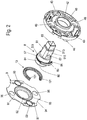
- the reference number 1 denotes a set of two handle bearings with two door handles 2, two cover rosettes 3, two lower rosettes 4 and a common profile pin.
- the profile pin 7 passes through the door leaf or the window frame in the installed state, not shown here, in a door leaf or a window frame and is coupled in the central area to a door or window lock not shown here, actuation being effected by rotating the profile pin 7 about its longitudinal axis the door or window lock takes place.
- two screw bolts 5 are provided in the variant shown here, which extend through respective openings 43 of the lower rosettes 4 and can be screwed into respective threaded sleeves 6.
- the screw bolts 5 are inserted into a lower rosette 4 lying on a first side of the door leaf or the window frame, while the threaded sleeves 6 are inserted from the opposite side of the door leaf through the lower rosette 4, whereby by tightening the screw bolts 5 in the threaded sleeves 6 the two lower rosettes 4 are clamped against each other in a stationary and rotationally fixed manner on the door leaf or the window frame.
- the following description relates to the interaction of a handle 21 of a door or window handle 2 with a cover rosette 3, a lower rosette 4 and a profile pin 7 received by these components.
- the structure of a corresponding handle mounting on the opposite side of the door leaf or window frame is preferably identical except for the arrangement of the screw bolts 5 and threaded sleeves 6.
- the handle mounting also has a bearing flange 8 which encompasses the profile pin 7 in the bearing opening 42 of the lower rosette 4 and which is fixed on the lower rosette 4.
- the bearing flange 8 has, as in Figures 2 and 3 is shown, on its side facing the pusher 2, a neck part 81 which can be inserted into the front opening 23 of the pusher neck 22 for fastening the pusher 2 to the profile pin 7.
- the fixing of the door or window handle 2 on the profile pin 7 and the bearing flange 8 is preferably carried out, as in FIG Figure 1 shown, via a bolt 25, which can be inserted, in particular screwed, into an opening 24 in the lateral surface of the handle neck 22 and a lateral opening 82 in the neck part 81 of the bearing flange 8 for the axial fixation of the trigger 2.
- the neck part 81 of the bearing flange 8 is, as in the Figures 2 and 3 shown, formed axially to a through opening 83 receiving the profile pin 7 in steps.
- the neck part 81 of the bearing flange 8 has a cylinder piece 811 which, in the assembled state, rests in the bearing opening 42 of the lower rosette 4.
- This cylinder piece 811 is followed by a handle connection piece 812 which, in the embodiment variant shown here, has a square cross-section with chamfered corners and, in the assembled state, with the corresponding Cross-section provided at the end face opening 23 in the trigger neck 22 of the trigger 2 rests.
- the opening 82 for receiving the bolt 25 is let into one of the side surfaces of this handle connection piece 812.
- the opening 82 is preferably designed as an internally threaded bore into which the bolt 25, preferably designed as a screw bolt, can be screwed.
- the handle connection piece 812 is followed by a guide piece 813 which projects even further into the opening 23 of the handle neck 22.
- One end of the profile pin 7 projects from this guide piece 813.
- the fixing of the cover rosette 3 on the lower rosette 4 is preferably done by clipping the cover rosette 3 onto the lower rosette 4.
- the cover rosette 3 consists of a cylindrical cover housing, in the end face of which a bearing opening 32 is provided, through which the bearing flange 8 with the received therein Profile pin 7 extends.
- the inner casing surface 33 of the cover rosette 3 is preferably contoured and can be latched onto an outer casing surface of the lower rosette 4, elastically radially inwardly compressible fixing elements 45 which, when the cover rosette 3 is slipped onto the lower rosette 4, can move radially inward and, after being turned on, lock with the Contour in the jacket inner surface 33 of the cover rosette 3 interact.
- the bearing flange 8 has two spring stops 86 arranged between the neck part 81 and a sleeve part 84 extending axially to the through opening 83 away from the neck part 81.
- the spring stops 86 serve to accommodate a spring element 10 that encompasses the bearing flange 8 circumferentially.
- the spring element 10 is on the one hand clamped on the spring stops 86 and on the other hand rests against spring stops 48 of the lower rosette 4 in a manner secured against displacement.
- This recess 49 is preferably formed in a side face of the lower rosette 4 facing away from the cover rosette 3.
- the recess 49 is formed radially closer to the bearing opening 42 than the two openings 43 in the base body 41 of the lower rosette 4, through which the screw bolts 5 for fixing the lower rosette 4 to the door leaf or window frame extend.
- the side surface of the lower rosette 4 receiving the spring element 10 is also, as in FIG Figures 1 to 3 shown, covered by a retaining disk 9.
- the retaining disk 9 also has openings 93 through which the screw bolts 5 are passed.
- the screw bolts 5 on the side of the retaining disk 9 are guided by positioning sleeves 44, which are arranged parallel to the profile pin 7 on the side surface of the lower rosette 4 receiving the spring element 10.
- the positioning sleeves 44 are made of a sufficiently elastic material that they can be pressed in through the openings 93 of the holding disk 9 with a slight radial compression and in a provided for this purpose Step on the outer circumferential surface of the positioning sleeves 44, the outer radius of which is slightly smaller than the front end of the positioning sleeve 44, enables the holding disk 9 to be axially fixed on the lower rosette 4.
- the retaining disk 9 also has a central opening 92 in which the sleeve part 84 of the bearing flange 8 is received.
- the retaining disk 9 In order to be able to fix the retaining disk 9 as close as possible to the side of the lower rosette 4 facing the retaining disk 9, the retaining disk 9 preferably has an annular recess 95 in which a partial cross section of the spring element 10 is received.
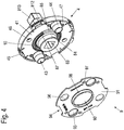
- the spring stops 86 of the bearing flange 8 are, as in FIG Figure 3 , Figure 4 and the Figures 9a and 9b shown, formed as ends of a collar 85 integrally formed between the neck part 81 and a sleeve part 84 of the bearing flange 8.
- each of the spring stops 86 of the bearing flange 8 preferably has a stop surface 863 formed by an end face of the collar 85 as well as a guide extension 861 extending from the stop surface 863 into the annular recess 49 of the lower rosette 4, on which an end section 101 of the Spring element 10 is attached in the assembled state of the spring element 10.
- the guide extension 861 is designed to be adapted to the inner contour of the spring element 10 and, in the variant embodiment shown here, in which the spring element is designed as a compression spring, in particular as a helical spring, has a semi-cylindrical shape.
- This guide web 862 serves to precisely guide the collar 5 in the annular recess 49 of the lower rosette 4.
- the spring stops 48 of the lower rosette 4 are preferably the end faces of a partially annular extending axially to the profile pin 7 from the bottom of the annular recess 49 of the lower rosette 4 Web 481, 482 formed.
- a guide groove 483 for guiding the guide web 862 of the bearing flange 8 is formed.
- the collar 85 forming the spring stops 86 is circumferentially provided a lip 87 with which the spring element 10 is fixed in the installed position in the annular recess 49 of the lower rosette 4 .
- the angle covered by the spring element 10 in the state resting on the two spring stops 48 of the lower rose 4, which corresponds to the neutral position of the door or window handle 2, is preferably between 240 ° and 300 °.
- a larger or smaller angular overlap is also conceivable, depending on the required angle of rotation for actuating the door or window handle 2.
Landscapes
- Engineering & Computer Science (AREA)
- Mechanical Engineering (AREA)
- Closing And Opening Devices For Wings, And Checks For Wings (AREA)
- Hinges (AREA)
- Lock And Its Accessories (AREA)
Applications Claiming Priority (1)
| Application Number | Priority Date | Filing Date | Title |
|---|---|---|---|
| PCT/EP2016/078540 WO2018095520A1 (de) | 2016-11-23 | 2016-11-23 | Drückerlagerung für einen tür- oder fensterdrücker und tür- oder fensterdrücker mit einer drückerlagerung |
Publications (2)
| Publication Number | Publication Date |
|---|---|
| EP3545150A1 EP3545150A1 (de) | 2019-10-02 |
| EP3545150B1 true EP3545150B1 (de) | 2020-09-02 |
Family
ID=57391975
Family Applications (1)
| Application Number | Title | Priority Date | Filing Date |
|---|---|---|---|
| EP16800954.6A Active EP3545150B1 (de) | 2016-11-23 | 2016-11-23 | Drückerlagerung für einen tür- oder fensterdrücker und tür- oder fensterdrücker mit einer drückerlagerung |
Country Status (5)
| Country | Link |
|---|---|
| EP (1) | EP3545150B1 (da) |
| CN (1) | CN109983189B (da) |
| DK (1) | DK3545150T3 (da) |
| ES (1) | ES2828732T3 (da) |
| WO (1) | WO2018095520A1 (da) |
Families Citing this family (2)
| Publication number | Priority date | Publication date | Assignee | Title |
|---|---|---|---|---|
| DE202019103678U1 (de) * | 2019-07-04 | 2020-10-06 | Franz Schneider Brakel Gmbh + Co Kg | Haltevorrichtung für einen Tür- oder Fensterdrücker |
| DE102023112864A1 (de) | 2023-04-17 | 2024-10-17 | Griffwerk GmbH | Beschlag für Türen oder Fenster |
Family Cites Families (8)
| Publication number | Priority date | Publication date | Assignee | Title |
|---|---|---|---|---|
| GB2095788B (en) * | 1981-04-01 | 1985-09-11 | Sheffield Brick Group The Ltd | Door handle spring return mechanism |
| US4784417A (en) * | 1986-01-31 | 1988-11-15 | W & F Manufacturing, Inc. | Door latch and deadbolt assembly |
| DE3614952C2 (de) * | 1986-05-02 | 1994-06-09 | Dieckmann Erich Normbau | Türbeschlag mit Türbetätigungselement und Türschild |
| US4998760A (en) * | 1989-10-13 | 1991-03-12 | Best Lock Corporation | Door handle return assembly |
| SG50654A1 (en) * | 1992-10-09 | 1998-07-20 | Gainsborough Hardware | Dual function lock mechanism |
| US5529354A (en) * | 1994-07-08 | 1996-06-25 | Wright Products Corp. | Spring pack assembly |
| TW578833U (en) * | 2003-04-17 | 2004-03-01 | Tong Lung Metal Ind Co Ltd | Reposition structure for lock |
| CA2570788C (en) * | 2004-06-22 | 2012-12-04 | Wabtec Holding Corporation | Mechanical release of release holding mechanism for hand brake |
-
2016
- 2016-11-23 DK DK16800954.6T patent/DK3545150T3/da active
- 2016-11-23 CN CN201680090965.1A patent/CN109983189B/zh active Active
- 2016-11-23 WO PCT/EP2016/078540 patent/WO2018095520A1/de not_active Ceased
- 2016-11-23 ES ES16800954T patent/ES2828732T3/es active Active
- 2016-11-23 EP EP16800954.6A patent/EP3545150B1/de active Active
Non-Patent Citations (1)
| Title |
|---|
| None * |
Also Published As
| Publication number | Publication date |
|---|---|
| ES2828732T3 (es) | 2021-05-27 |
| DK3545150T3 (da) | 2020-12-07 |
| WO2018095520A1 (de) | 2018-05-31 |
| EP3545150A1 (de) | 2019-10-02 |
| CN109983189A (zh) | 2019-07-05 |
| CN109983189B (zh) | 2021-06-29 |
Similar Documents
| Publication | Publication Date | Title |
|---|---|---|
| EP3271530B1 (de) | Halteelement für einen tür- oder fensterdrücker und anordnung eines tür- oder fensterdrückers an einer aufnahmeöffnung eines fensterrahmens, eines türblatts oder dergleichen | |
| EP3867465B1 (de) | Vorrichtung zur fixierung eines tür- oder fensterdrückers | |
| EP2796645B1 (de) | Riegelschloss eines Möbels | |
| DE19544580C1 (de) | Lenkradbefestigung | |
| EP3545150B1 (de) | Drückerlagerung für einen tür- oder fensterdrücker und tür- oder fensterdrücker mit einer drückerlagerung | |
| DE202013100325U1 (de) | Drückerlagerung eines Tür- oder Fensterdrückers | |
| EP2059371B1 (de) | Drehlagerung für kabelschneider, scheren oder blechscheren | |
| EP3760816A1 (de) | Haltevorrichtung für einen tür- oder fensterdrücker | |
| DE102008020986A1 (de) | Vorrichtung mit einem Unterteil und einer Rückholfeder zur drehbaren Lagerung eines Ausstattungsteils, insbesondere eines Türdrückers | |
| EP2565351B1 (de) | Griffanordnung | |
| EP2034109B1 (de) | Rosetteneinrichtung mit einer Sicherungseinrichtung | |
| EP3867467B1 (de) | Drückerlagerung, tür- oder fensterdrücker mit einer drückerlagerung | |
| DE4041207C1 (en) | Furniture lock with slide bolt actuated by cylinder or key - has cylinder lock core with drive part angularly adjustable and arrestable in position | |
| EP2927414B1 (de) | Seilspannvorrichtung für einen Fensterbehang | |
| DE19919283A1 (de) | Schließzylinder | |
| EP1918492A2 (de) | Beschlag für die Befestigung eines Drückers an einer Tür oder einem Fester | |
| EP3363969A1 (de) | Betätigungshandhabe | |
| EP2034110B1 (de) | Rosetteneinrichtung mit einer Sicherungseinrichtung | |
| EP2369099B1 (de) | Türrosette | |
| EP0663498A1 (de) | Schliesszylinder | |
| DE10311546A1 (de) | Vorrichtung zur lösbaren, axialen Festlegung einer Handhabe an einem Lagerteil, z. B. Türdrücker- oder Fenstergriffanordnung | |
| DE19844827C2 (de) | Elektrischer Sicherheitsschalter | |
| DE102005057766B3 (de) | Beschlag für Türen, Fenster oder dergleichen | |
| DE29708693U1 (de) | Rolle | |
| EP3540156A1 (de) | Drückerlagerung |
Legal Events
| Date | Code | Title | Description |
|---|---|---|---|
| STAA | Information on the status of an ep patent application or granted ep patent |
Free format text: STATUS: UNKNOWN |
|
| STAA | Information on the status of an ep patent application or granted ep patent |
Free format text: STATUS: THE INTERNATIONAL PUBLICATION HAS BEEN MADE |
|
| PUAI | Public reference made under article 153(3) epc to a published international application that has entered the european phase |
Free format text: ORIGINAL CODE: 0009012 |
|
| STAA | Information on the status of an ep patent application or granted ep patent |
Free format text: STATUS: REQUEST FOR EXAMINATION WAS MADE |
|
| 17P | Request for examination filed |
Effective date: 20190531 |
|
| AK | Designated contracting states |
Kind code of ref document: A1 Designated state(s): AL AT BE BG CH CY CZ DE DK EE ES FI FR GB GR HR HU IE IS IT LI LT LU LV MC MK MT NL NO PL PT RO RS SE SI SK SM TR |
|
| AX | Request for extension of the european patent |
Extension state: BA ME |
|
| DAV | Request for validation of the european patent (deleted) | ||
| DAX | Request for extension of the european patent (deleted) | ||
| GRAP | Despatch of communication of intention to grant a patent |
Free format text: ORIGINAL CODE: EPIDOSNIGR1 |
|
| STAA | Information on the status of an ep patent application or granted ep patent |
Free format text: STATUS: GRANT OF PATENT IS INTENDED |
|
| INTG | Intention to grant announced |
Effective date: 20200608 |
|
| GRAS | Grant fee paid |
Free format text: ORIGINAL CODE: EPIDOSNIGR3 |
|
| GRAA | (expected) grant |
Free format text: ORIGINAL CODE: 0009210 |
|
| STAA | Information on the status of an ep patent application or granted ep patent |
Free format text: STATUS: THE PATENT HAS BEEN GRANTED |
|
| AK | Designated contracting states |
Kind code of ref document: B1 Designated state(s): AL AT BE BG CH CY CZ DE DK EE ES FI FR GB GR HR HU IE IS IT LI LT LU LV MC MK MT NL NO PL PT RO RS SE SI SK SM TR |
|
| REG | Reference to a national code |
Ref country code: GB Ref legal event code: FG4D Free format text: NOT ENGLISH |
|
| REG | Reference to a national code |
Ref country code: AT Ref legal event code: REF Ref document number: 1308971 Country of ref document: AT Kind code of ref document: T Effective date: 20200915 Ref country code: CH Ref legal event code: EP |
|
| REG | Reference to a national code |
Ref country code: DE Ref legal event code: R096 Ref document number: 502016011056 Country of ref document: DE |
|
| REG | Reference to a national code |
Ref country code: CH Ref legal event code: NV Representative=s name: ISLER AND PEDRAZZINI AG, CH Ref country code: IE Ref legal event code: FG4D Free format text: LANGUAGE OF EP DOCUMENT: GERMAN |
|
| REG | Reference to a national code |
Ref country code: DK Ref legal event code: T3 Effective date: 20201202 |
|
| REG | Reference to a national code |
Ref country code: NL Ref legal event code: FP |
|
| REG | Reference to a national code |
Ref country code: LT Ref legal event code: MG4D |
|
| PG25 | Lapsed in a contracting state [announced via postgrant information from national office to epo] |
Ref country code: LT Free format text: LAPSE BECAUSE OF FAILURE TO SUBMIT A TRANSLATION OF THE DESCRIPTION OR TO PAY THE FEE WITHIN THE PRESCRIBED TIME-LIMIT Effective date: 20200902 Ref country code: FI Free format text: LAPSE BECAUSE OF FAILURE TO SUBMIT A TRANSLATION OF THE DESCRIPTION OR TO PAY THE FEE WITHIN THE PRESCRIBED TIME-LIMIT Effective date: 20200902 Ref country code: BG Free format text: LAPSE BECAUSE OF FAILURE TO SUBMIT A TRANSLATION OF THE DESCRIPTION OR TO PAY THE FEE WITHIN THE PRESCRIBED TIME-LIMIT Effective date: 20201202 Ref country code: NO Free format text: LAPSE BECAUSE OF FAILURE TO SUBMIT A TRANSLATION OF THE DESCRIPTION OR TO PAY THE FEE WITHIN THE PRESCRIBED TIME-LIMIT Effective date: 20201202 Ref country code: GR Free format text: LAPSE BECAUSE OF FAILURE TO SUBMIT A TRANSLATION OF THE DESCRIPTION OR TO PAY THE FEE WITHIN THE PRESCRIBED TIME-LIMIT Effective date: 20201203 Ref country code: SE Free format text: LAPSE BECAUSE OF FAILURE TO SUBMIT A TRANSLATION OF THE DESCRIPTION OR TO PAY THE FEE WITHIN THE PRESCRIBED TIME-LIMIT Effective date: 20200902 Ref country code: HR Free format text: LAPSE BECAUSE OF FAILURE TO SUBMIT A TRANSLATION OF THE DESCRIPTION OR TO PAY THE FEE WITHIN THE PRESCRIBED TIME-LIMIT Effective date: 20200902 |
|
| PG25 | Lapsed in a contracting state [announced via postgrant information from national office to epo] |
Ref country code: PL Free format text: LAPSE BECAUSE OF FAILURE TO SUBMIT A TRANSLATION OF THE DESCRIPTION OR TO PAY THE FEE WITHIN THE PRESCRIBED TIME-LIMIT Effective date: 20200902 Ref country code: RS Free format text: LAPSE BECAUSE OF FAILURE TO SUBMIT A TRANSLATION OF THE DESCRIPTION OR TO PAY THE FEE WITHIN THE PRESCRIBED TIME-LIMIT Effective date: 20200902 Ref country code: LV Free format text: LAPSE BECAUSE OF FAILURE TO SUBMIT A TRANSLATION OF THE DESCRIPTION OR TO PAY THE FEE WITHIN THE PRESCRIBED TIME-LIMIT Effective date: 20200902 |
|
| PG25 | Lapsed in a contracting state [announced via postgrant information from national office to epo] |
Ref country code: RO Free format text: LAPSE BECAUSE OF FAILURE TO SUBMIT A TRANSLATION OF THE DESCRIPTION OR TO PAY THE FEE WITHIN THE PRESCRIBED TIME-LIMIT Effective date: 20200902 Ref country code: PT Free format text: LAPSE BECAUSE OF FAILURE TO SUBMIT A TRANSLATION OF THE DESCRIPTION OR TO PAY THE FEE WITHIN THE PRESCRIBED TIME-LIMIT Effective date: 20210104 Ref country code: CZ Free format text: LAPSE BECAUSE OF FAILURE TO SUBMIT A TRANSLATION OF THE DESCRIPTION OR TO PAY THE FEE WITHIN THE PRESCRIBED TIME-LIMIT Effective date: 20200902 Ref country code: EE Free format text: LAPSE BECAUSE OF FAILURE TO SUBMIT A TRANSLATION OF THE DESCRIPTION OR TO PAY THE FEE WITHIN THE PRESCRIBED TIME-LIMIT Effective date: 20200902 Ref country code: SM Free format text: LAPSE BECAUSE OF FAILURE TO SUBMIT A TRANSLATION OF THE DESCRIPTION OR TO PAY THE FEE WITHIN THE PRESCRIBED TIME-LIMIT Effective date: 20200902 |
|
| REG | Reference to a national code |
Ref country code: ES Ref legal event code: FG2A Ref document number: 2828732 Country of ref document: ES Kind code of ref document: T3 Effective date: 20210527 |
|
| PG25 | Lapsed in a contracting state [announced via postgrant information from national office to epo] |
Ref country code: AL Free format text: LAPSE BECAUSE OF FAILURE TO SUBMIT A TRANSLATION OF THE DESCRIPTION OR TO PAY THE FEE WITHIN THE PRESCRIBED TIME-LIMIT Effective date: 20200902 Ref country code: IS Free format text: LAPSE BECAUSE OF FAILURE TO SUBMIT A TRANSLATION OF THE DESCRIPTION OR TO PAY THE FEE WITHIN THE PRESCRIBED TIME-LIMIT Effective date: 20210102 |
|
| REG | Reference to a national code |
Ref country code: DE Ref legal event code: R097 Ref document number: 502016011056 Country of ref document: DE |
|
| PG25 | Lapsed in a contracting state [announced via postgrant information from national office to epo] |
Ref country code: MC Free format text: LAPSE BECAUSE OF FAILURE TO SUBMIT A TRANSLATION OF THE DESCRIPTION OR TO PAY THE FEE WITHIN THE PRESCRIBED TIME-LIMIT Effective date: 20200902 Ref country code: SK Free format text: LAPSE BECAUSE OF FAILURE TO SUBMIT A TRANSLATION OF THE DESCRIPTION OR TO PAY THE FEE WITHIN THE PRESCRIBED TIME-LIMIT Effective date: 20200902 |
|
| PLBE | No opposition filed within time limit |
Free format text: ORIGINAL CODE: 0009261 |
|
| STAA | Information on the status of an ep patent application or granted ep patent |
Free format text: STATUS: NO OPPOSITION FILED WITHIN TIME LIMIT |
|
| PG25 | Lapsed in a contracting state [announced via postgrant information from national office to epo] |
Ref country code: LU Free format text: LAPSE BECAUSE OF NON-PAYMENT OF DUE FEES Effective date: 20201123 |
|
| 26N | No opposition filed |
Effective date: 20210603 |
|
| PG25 | Lapsed in a contracting state [announced via postgrant information from national office to epo] |
Ref country code: SI Free format text: LAPSE BECAUSE OF FAILURE TO SUBMIT A TRANSLATION OF THE DESCRIPTION OR TO PAY THE FEE WITHIN THE PRESCRIBED TIME-LIMIT Effective date: 20200902 |
|
| PG25 | Lapsed in a contracting state [announced via postgrant information from national office to epo] |
Ref country code: IE Free format text: LAPSE BECAUSE OF NON-PAYMENT OF DUE FEES Effective date: 20201123 |
|
| PG25 | Lapsed in a contracting state [announced via postgrant information from national office to epo] |
Ref country code: TR Free format text: LAPSE BECAUSE OF FAILURE TO SUBMIT A TRANSLATION OF THE DESCRIPTION OR TO PAY THE FEE WITHIN THE PRESCRIBED TIME-LIMIT Effective date: 20200902 Ref country code: MT Free format text: LAPSE BECAUSE OF FAILURE TO SUBMIT A TRANSLATION OF THE DESCRIPTION OR TO PAY THE FEE WITHIN THE PRESCRIBED TIME-LIMIT Effective date: 20200902 Ref country code: CY Free format text: LAPSE BECAUSE OF FAILURE TO SUBMIT A TRANSLATION OF THE DESCRIPTION OR TO PAY THE FEE WITHIN THE PRESCRIBED TIME-LIMIT Effective date: 20200902 |
|
| PG25 | Lapsed in a contracting state [announced via postgrant information from national office to epo] |
Ref country code: MK Free format text: LAPSE BECAUSE OF FAILURE TO SUBMIT A TRANSLATION OF THE DESCRIPTION OR TO PAY THE FEE WITHIN THE PRESCRIBED TIME-LIMIT Effective date: 20200902 |
|
| REG | Reference to a national code |
Ref country code: CH Ref legal event code: U11 Free format text: ST27 STATUS EVENT CODE: U-0-0-U10-U11 (AS PROVIDED BY THE NATIONAL OFFICE) Effective date: 20251201 |
|
| PGFP | Annual fee paid to national office [announced via postgrant information from national office to epo] |
Ref country code: NL Payment date: 20251104 Year of fee payment: 10 |
|
| PGFP | Annual fee paid to national office [announced via postgrant information from national office to epo] |
Ref country code: DE Payment date: 20251010 Year of fee payment: 10 |
|
| PGFP | Annual fee paid to national office [announced via postgrant information from national office to epo] |
Ref country code: GB Payment date: 20251031 Year of fee payment: 10 |
|
| PGFP | Annual fee paid to national office [announced via postgrant information from national office to epo] |
Ref country code: AT Payment date: 20251104 Year of fee payment: 10 |
|
| PGFP | Annual fee paid to national office [announced via postgrant information from national office to epo] |
Ref country code: IT Payment date: 20251128 Year of fee payment: 10 Ref country code: DK Payment date: 20251031 Year of fee payment: 10 |
|
| PGFP | Annual fee paid to national office [announced via postgrant information from national office to epo] |
Ref country code: FR Payment date: 20251031 Year of fee payment: 10 |
|
| PGFP | Annual fee paid to national office [announced via postgrant information from national office to epo] |
Ref country code: BE Payment date: 20251104 Year of fee payment: 10 |
|
| PGFP | Annual fee paid to national office [announced via postgrant information from national office to epo] |
Ref country code: CH Payment date: 20251201 Year of fee payment: 10 |
|
| PGFP | Annual fee paid to national office [announced via postgrant information from national office to epo] |
Ref country code: ES Payment date: 20251216 Year of fee payment: 10 |