EP3545803A1 - Système distributeur pliable - Google Patents
Système distributeur pliable Download PDFInfo
- Publication number
- EP3545803A1 EP3545803A1 EP19150391.1A EP19150391A EP3545803A1 EP 3545803 A1 EP3545803 A1 EP 3545803A1 EP 19150391 A EP19150391 A EP 19150391A EP 3545803 A1 EP3545803 A1 EP 3545803A1
- Authority
- EP
- European Patent Office
- Prior art keywords
- base
- cover
- canister
- support
- wipe
- Prior art date
- Legal status (The legal status is an assumption and is not a legal conclusion. Google has not performed a legal analysis and makes no representation as to the accuracy of the status listed.)
- Withdrawn
Links
Images


Classifications
-
- A—HUMAN NECESSITIES
- A47—FURNITURE; DOMESTIC ARTICLES OR APPLIANCES; COFFEE MILLS; SPICE MILLS; SUCTION CLEANERS IN GENERAL
- A47K—SANITARY EQUIPMENT; ACCESSORIES THEREFOR, e.g. TOILET ACCESSORIES
- A47K10/00—Body-drying implements; Toilet paper; Holders therefor
- A47K10/24—Towel dispensers; Toilet paper dispensers
- A47K10/32—Dispensers for paper towels or toilet paper
-
- A—HUMAN NECESSITIES
- A47—FURNITURE; DOMESTIC ARTICLES OR APPLIANCES; COFFEE MILLS; SPICE MILLS; SUCTION CLEANERS IN GENERAL
- A47K—SANITARY EQUIPMENT; ACCESSORIES THEREFOR, e.g. TOILET ACCESSORIES
- A47K10/00—Body-drying implements; Toilet paper; Holders therefor
- A47K10/16—Paper towels; Toilet paper; Holders therefor
- A47K10/18—Holders; Receptacles
-
- A—HUMAN NECESSITIES
- A47—FURNITURE; DOMESTIC ARTICLES OR APPLIANCES; COFFEE MILLS; SPICE MILLS; SUCTION CLEANERS IN GENERAL
- A47K—SANITARY EQUIPMENT; ACCESSORIES THEREFOR, e.g. TOILET ACCESSORIES
- A47K10/00—Body-drying implements; Toilet paper; Holders therefor
- A47K10/24—Towel dispensers; Toilet paper dispensers
- A47K10/32—Dispensers for paper towels or toilet paper
- A47K10/34—Dispensers for paper towels or toilet paper dispensing from a web, e.g. with mechanical dispensing means
- A47K10/38—Dispensers for paper towels or toilet paper dispensing from a web, e.g. with mechanical dispensing means the web being rolled-up
- A47K10/3809—Dispensers for paper towels or toilet paper dispensing from a web, e.g. with mechanical dispensing means the web being rolled-up with roll spindles which are not directly supported
- A47K10/3818—Dispensers for paper towels or toilet paper dispensing from a web, e.g. with mechanical dispensing means the web being rolled-up with roll spindles which are not directly supported with a distribution opening which is perpendicular to the rotation axis
-
- A—HUMAN NECESSITIES
- A47—FURNITURE; DOMESTIC ARTICLES OR APPLIANCES; COFFEE MILLS; SPICE MILLS; SUCTION CLEANERS IN GENERAL
- A47K—SANITARY EQUIPMENT; ACCESSORIES THEREFOR, e.g. TOILET ACCESSORIES
- A47K10/00—Body-drying implements; Toilet paper; Holders therefor
- A47K10/24—Towel dispensers; Toilet paper dispensers
- A47K10/32—Dispensers for paper towels or toilet paper
- A47K2010/3233—Details of the housing, e.g. hinges, connection to the wall
-
- A—HUMAN NECESSITIES
- A47—FURNITURE; DOMESTIC ARTICLES OR APPLIANCES; COFFEE MILLS; SPICE MILLS; SUCTION CLEANERS IN GENERAL
- A47K—SANITARY EQUIPMENT; ACCESSORIES THEREFOR, e.g. TOILET ACCESSORIES
- A47K10/00—Body-drying implements; Toilet paper; Holders therefor
- A47K10/24—Towel dispensers; Toilet paper dispensers
- A47K10/32—Dispensers for paper towels or toilet paper
- A47K2010/3266—Wet wipes
Definitions
- the present application relates generally to a system and method of providing a pull-through consumable product dispenser for use in dispensing consumer products proximate a point of use, and more particularly, to a system for supporting and dispensing wipes formed of a web material wherein the dispense activity is performed by manual extraction of discrete wipes from a container that removeably cooperates with a respective container supporting dispenser.
- wet wipes are sheets of a web or fabric type materials that are moistened with a fluid associated with the intended use of the discrete wipes.
- wet wipes are provided in various configurations associated with the intended use of the discrete wipes. Some such uses include cleaning parts of the human body, hand wipes, use as toilet paper or baby wipes, degreasers, electronics cleaners, dust wipes, automotive applications including tire, leather, window, glass, and/or vinyl or plastic treatment, cleaning, and/or conditioning materials, etc. It is appreciated that the list provided above is in no way exhaustive or all-inclusive of the intended use of such wet wipes.
- the material and/or construction of the web material as well as the material associated with moistening the wipes can be provided in a plethora of combinations associated with the intended use of the discrete wet wipes for cleaning, sanitation, and/or surface or material conditioning treatments. It is further appreciated that, depending on the intended use of the discrete wipes, some such wipes can be provided in a non-moistened or dry configuration.
- wipes are commonly provided in a disposable bag or canister that includes a dispensing structure that allows sequential extraction of one or more wipes when desired.
- the dispensing structure commonly includes a lid or other closure assembly that movably cooperates with a cover or bezel associated with the container.
- the lid When provided to dispense wet or pre-moistened wipes, the lid commonly provides a sealed interaction with the remainder of the container or cover to mitigate drying out of the wipes prior to use.
- Some wet wipe containers are provided as disposable bags of wet wipes whereas other wet wipe dispensing containers are formed as selectively operable boxes or canisters that are configured to be re-useable and/or refillable.
- dispensers include a wipe separation structure defined by the cover or lid of the contained and that is configured to interact with the web material of the wipes to effectuate sequential dispensing and/or separation between adjacent wipes until the contents of the container are consumed. That is, many dispensing structures are constructed to cooperate with the web or cloth material of the wipes so that at least an end portion of a subsequent wipe is restrained by the separation structure in a manner such that the end of the subsequent wipe can be grasped by the user but does not otherwise interfere with the desired opening and closing of the lid and a preferred sealed interaction between the lid and the remainder of the cover or container after each use of a discrete wipe(s).
- wipe dispenser containers are also provided as supplemental containers or dispensers that are configured to enclose a container of wet wipes.
- Such containers and dispenser systems suffer from the additional drawback of being not readily visually inspectable to assess the availability of a container of wet wipes being contained therein.
- such approaches require placement and/or storage of the dispenser that generally encloses the wet wipe container that occupies a space associated with the use environment that is at least as obtrusive as displaying or presenting a container of wet wipes even when a supply of wet wipes are unavailable for dispensing.
- a wet wipe dispensing support or dispenser system that restrains a container of wet wipes to accommodate single handed interaction therewith.
- a wet wipe container support system that provides a sealed interaction with an underlying container of wet wipes.
- a wet wipe container support system that provides sequential but separable extraction of the wet wipes with presentation of the subsequent wet wipe in a readily single handed dispensable orientation relative to the support system.
- a collapsible wet wipe container support system that is movable between a deployed orientation when a container of wet wipes is associated therewith and a collapsible orientation thereby limiting the space occupied by the container support system when a container of wet wipes is not associated therewith.
- a collapsible wet wipe container support system wherein the components of the support system are movable but non-removable relative to one another as the container support system transitions between the deployed and stowed orientations.
- the present application discloses a wet wipe container support system that overcomes one or more of the shortcomings disclosed above.
- a collapsible wet wipe dispenser support system that includes a base.
- a cover is connected to a first portion of the base and is constructed to cooperate with a dispense end of a wet wipe container.
- a lid is connected to the cover and movable between an open position and a closed position relative to the cover.
- a support is connected to a second portion of the base such that the cover and the support are located at generally opposite longitudinal ends of the wet wipe container when a container of wet wipes is associated with the collapsible wet wipe dispenser support system.
- a collapsible wet wipe dispenser system having a base that includes a first portion and a second portion that are movable relative to one another.
- a cover is connected to the first portion of the base and is constructed to cooperate with a dispense end of a wet wipe container.
- a lid is connected to the cover and movable between an open position and a closed position relative to the cover.
- a support is connected to the second portion of the base such that the cover and the support are located at generally opposite longitudinal ends of the base.
- a wet wipe canister support system having a rail that includes a first portion and a second portion that are movable relative to one another between a first orientation and a second orientation to manipulate a longitudinal length of the rail.
- a cover is connected to the first portion of the rail and movable between a first position wherein the cover extends in a crossing direction relative to the longitudinal length of the rail and a second position wherein the cover extends in a direction generally aligned with the longitudinal length of the rail.
- a lid is connected to the cover and moveable relative thereto between an open position and a closed position.
- a support is connected to the second portion of the rail and movable between a first position wherein the support extends in a crossing direction relative to the longitudinal length of the rail and a second position wherein the support extends in a direction generally aligned with the longitudinal length of the rail such that the support and at least a majority of the rail are disposed behind the cover when the cover is oriented in the second position.
- the method includes providing a base.
- a canister support is provided and configured to cooperate with the base and engage a lower end of a canister of wet wipes when a canister of wet wipes is associated with the collapsible wet wipe canister support system.
- a cover is provided that is configured to cooperate with the base at a location that is offset from the canister support and cooperate with a dispense end of a canister of wet wipes when a canister of wet wipes is associated with the collapsible wet wipe canister support system.
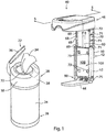
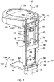
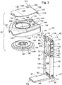
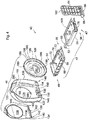
- Figs. 1-7 show various views of a wet wipe container support, bracket, bracket system, or support system 40 according to a preferred embodiment of the present application.
- Support system 40 is constructed to removably cooperate with a dispenser or container 22 of wet wipes 34.
- container 22 includes a canister 24 that is generally defined by a closed end 26 and a dispense end 28 that are oriented at generally opposite longitudinal ends of canister 24.
- dispense end 28 of container 22 commonly includes a cover 30 that defines a dispense opening 32 associated with extracting discrete wet wipes 34 from container 22.
- cover 30 When intended to form a dispenser rather than as a refill or refill cartridge, cover 30 commonly includes a lid 36 that cooperates with cover 30 to be movable between a closed position wherein lid 36 generally overlies dispense opening 32 and preferably sealingly cooperates with cover 30 to generally enclose the cavity associated with container 22 and an open position as shown in Fig. 1 to allow access and extraction of discrete wet wipes 34 disposed in container 22 in a generally sequential manner until the contents of container 22 are depleted.
- container 22 could be configured to cooperate with support system 40 wherein a portion of or the entirety of cover 30 and/or lid 36 be removed from container 22 or disposed in an open configuration so as to allow the passage of discrete wipes 34 through the respective cover and/or lid associated with support system 40 to which container 22 is associated.
- Cover 30 includes a radial perimeter surface 38 that is secured to canister 24.
- container 22 and/or canister 24 is constructed to removably cooperate with support systems 40.
- the exterior perimeter surface 38 of cover 30, the surface of canister 24 disposed generally therebehind, and/or the dispense opening 32 associated with container 22 can be constructed to removeably cooperate with either or both of support systems 40, 300. That is, when container 22 is provided as a "refill" modality constructed for cooperation with support system 40, container 22 could be provided with a solid bodied cover that omits operable lid 36 or alternatively with a removable seal associated with dispense end 28 of canister 24 and/or container 22.
- container 22 may be provided with a removable or otherwise disposed cover, such as a seal foil or the like, secured to container 22 to maintain the moisture content thereof prior to use or operative association with a respective support system 40 as disclosed herein. It should be further appreciated that, after acquisition of a suitable canister 22, refills of wet wipes could be provided in a bagged configuration that is subsequently associated with canister 24 to effectuate continued utilization of the support system 40. Such a consideration further mitigates the generation of waste associated with providing a readily accessible supply of wet wipes 34.
- support systems 40 is provided with a dispense opening shaped to accommodate incremental and sequential dispensing of a supply of wet wipes 34 associated with the canister 24. It should be appreciated that such a consideration facilitates use of dispense opening with multiple supplies of wet wipes 34. As disclosed above, such a consideration accommodates bag packaging of rolls of wet wipes 34 such that the contents of such a bag, i.e. the wipes and the moisture treatment associated therewith, could be associated with a container of canister associated with a respective support system 40. It is further appreciated that it may be desirable to deploy multiple support systems 40 in certain use environments such that ready access to wet wipes 34 having different moisture treatment can be readily accessible.
- container 22 could include a suitable lid structure and be constructed to cooperate with a respective support system 40 when the lid is in the open orientation relative to the underlying cover and the container is operationally associated with a respective support system 40.
- each support systems 40 is constructed to securely cooperate with a respective wet wipe container 22 in a manner that maintains the moisture content associated with use of the wet wipes 34 associated therewith and in a manner that accommodates sequential dispensing of the wet wipes 34, and facilitates single-handed operation of the lid or closure associated with facilitating selective access to the wet wipes 34 to be dispensed.
- support system 40 is constructed to securely cooperate with wipe containers 22 of various longitudinal lengths and circumferences or shapes while maintaining the moisture content associated with use of the wet wipes 34 associated therewith.
- wet wipe container support system 40 includes a base assembly, rail, or base 42, a support 44, and a cover assembly 46.
- Support 44 and cover assembly 46 are associated with a lower longitudinal end portion 47 and an upper longitudinal end portion 49 of base 42, respectively, such that support 44 and cover assembly 46 are offset from one another relative to a longitudinal axis, indicated by line 51, of base 42.
- Base 42 includes an upper or first portion 50 and a lower or second portion 52 that are movable relative to one another along longitudinal axis 51 as disclosed further below.
- First portion 50 of base 42 defines a first end 54 that is constructed to cooperate with cover assembly 46 such that cover assembly 46 is movable relative thereto.
- a lower end 56 of first portion 50 of base 42 includes a stop 58 that is constructed to selectively limit the outward longitudinal translation of second portion 52 of base 42 relative to first portion 50 thereof.
- a biasing device such as a ribbon spring 60 or the like includes a first end 62 that is secured to first portion 50 of base 42 and a second end 64 that is secured to second portion 52 of base 42. Ribbon spring 60 is oriented and constructed to allow outward longitudinal translation of second portion 52 of base 42 relative to first portion 50 thereof. Said in another way, biasing device 60 is constructed and oriented to bias base 42 toward a shorter longitudinal length or dimension. It is further appreciated that biasing base 42 toward a shorter longitudinal length biases support 44 and cover assembly 46 toward one another relative to the direction associated with longitudinal axis 51 of base 42.
- First portion 50 of base 42 preferably includes one or more ribs 68, 70 that extend in a longitudinal direction.
- ribs 68, 70 are oriented along opposing opposite lateral edges a first base portion 50.
- a series of tabs 69 extend generally perpendicular from a distal edge of rib 68 while a series of tabs 71 extends generally perpendicular from a distal edge of rib 70 at a longitudinal position approximately equal to the series of tabs 69.
- tabs 69, 71 engage with the second portion 52 of base 42 as to provide for incremental step-wise movement of the second portion 52 along the longitudinal length of the ribs 68, 70 to accommodate variable heights or longitudinal lengths of wipe containers 22.
- One or more apertures or holes 72 extend laterally through first portion 50 of base 42 and are constructed and oriented to receive fasteners associated with securing base 42 relative to a support surface, such as a wall, racking, or the like. Holes 72 are oriented laterally inboard relative to ribs 68, 70 and are constructed to allow slidable association between first and second portions 50, 52 of base 42 when respective fastener are associated therewith.
- Second portion 52 of base 42 includes one or more grooves or channels 76, 78 that are preferably formed along the opposite lateral edges thereof. Channels 76, 78 are constructed, shaped, and oriented to accommodate slidable association between first and second portions 50, 52 of base 42. Biasing device 60 is oriented to bias canister support 44 toward cover assembly 46 relative to the longitudinal translation direction 51 associated with the slideable cooperation of first and second portions 50, 52 of base 42.
- One or more apertures or holes 73 extend laterally through second portion 52 of base 42 and are constructed and oriented to overly holes 72, which receive fasteners associated with securing base 42 relative to a support surface, such as a wall, rack, or the like.
- fasteners may pass through holes 73 without engagement therewith when securing base 42 to a support surface when first and second portions 50, 52 are oriented to substantially overlie one another.
- a lower edge of second portion 52 of base 42 includes a boss or hinge pin 75 that extends between the opposite lateral edges of the second portion 52 of the base 42 and is configured to pivotably engage with the canister support 44, as described below. It is appreciated that boss of hinge pin 75 could alternatively be configured to extend from canister support 44 and cooperate with a cavity defined by second portion 52 of base 42 to provide the desired rotational interaction between base 42 and support 44.
- stop 58 is oriented to interfere with a projection 80 associated with second portion 52 of base 42.
- the cooperation of stop 58 with projection 80 prevents unintended or undesired separation between first portion 50 and second portion 52 of base 42 during association of container 22 with support system 40.
- a canister 24 associated with support system 40 is securely captured between support 44 and a support facing side of cover assembly 46.
- canister support 44 is generally defined by a generally planar body 84 that includes a stop 86 and one or more arcuate recesses 88 configured to receive and pivotably engage hinge pin 75 defined by second portion 50 of base 42 to collectively form hinge 90.
- arcuate recesses 88 are constructed to slideably or snap fittingly cooperate with respective hinge pin 75 associated with a lower end portion 96 of second base portion 52.
- the stop 86 associated with canister support 44 is constructed to engage or abut a projection 94 extending from the rearward facing surface 98 of second base portion 52.
- Such a construction limits downward lateral deflection and/or rotation, as indicated by arrow 100, of a distal end 102 of support 44 relative to second portion 52 of base 42.
- a rear edge 92 of the body 84 of the canister support 44 may extend rearwardly from the stop 86 to a distance that engages a support surface, thereby further mitigating downward lateral deflection and/or rotation of support 44 relative to base 42.
- support 44 cooperates with base 42 to allow approximately 90 degrees of relative rotation therebetween.
- hinge pin 75 and arcuate recesses 88 at hinge 90 allows upward rotation, as indicated by arrow 104, of support 44 relative to second portion 52 of base 42 such that, when not needed or not in use, distal end 102 of support 44 can be oriented in close proximity to a forward facing surface 108 of second portion 52 of base 42.
- the forward facing surface 108 of the second portion 52 may be slightly recessed relative to the opposing lateral edges of the second portion 52, as to form a receiving void 109 configured to receive the support 44 when not in use.
- support 44 when deployed, support 44 extends in a generally crossing direction relative to the longitudinal axis 51 of base 42 and when stowed or not in use, support 44 extends in a direction that is generally aligned with the longitudinal axis of base 42. It should be appreciated that, when deployed, support 44 extends in a generally crossing direction relative to base 42 thereby providing at least some degree of support of a container 22 or canister 24 associated with support system 40.
- support 44 when oriented in a stowed orientation relative to base 42, support 44 is stowed or stored in an orientation wherein cover assembly 46 can generally overlie at least a substantial portion, preferably at least 51% of the vertically oriented surface area of base 42. More preferably, the entirety of base 42 and support 44 can be disposed behind cover assembly 46 when no container 22 or canister 24 is associated with support system 40.
- cover assembly 46 can generally overlie at least a substantial portion, preferably at least 51% of the vertically oriented surface area of base 42. More preferably, the entirety of base 42 and support 44 can be disposed behind cover assembly 46 when no container 22 or canister 24 is associated with support system 40.
- Such considerations allow support system 40 to be readily visually identifiable as having a supply of wipes 34 being associated therewith when configured for use and achieve a substantially compact and less obtrusive configuration when collapsed or no wipes are otherwise associated therewith.
- biasing device 60 is secured to first and second portions 50, 52 of base 42 and configured to bias lower end portion 96 of second portion 52 of base 42 toward upper or first end 54 of first portion 50 of base 42 when no container 22 is associated therewith.
- the bias associated with biasing device 60 can be readily overcome by a user gripping lower end portion 96 and effectuating downward longitudinal translation of lower base portion 52 relative to upper base portion 50 during loading and unloading operations of support system 40.
- biasing device 60 may be omitted and the tactile or overlapping cooperation of a respective set of tabs 69, 71 with second portion 52 of base 42 may provide sufficient interference to retain a desired orientation of first portion 50 and second portion 52 of base 42 relative to one another during use of support system 40.
- biasing device 60 biases second portion 42 of base 42 into an overlapping configuration relative to first portion 50 such that cover assembly 46 generally overlies support 44, as well as at least a substantial portion of at least 51% of the elevational surface area, if not the entirety of, base 42 when support system 40 is oriented in a collapsed or non-use orientation.
- upper or first end 54 of first portion 50 of base 42 includes a pair of cavities 110, 112 that extend in opposite lateral directions, as indicated by arrow 114, that are constructed to snap fittingly cooperate with respective projections 114, 116 generally defined by a support facing, canister facing side, or underside 118 of a cover bezel or simply a cover 120 defined by cover assembly 46.
- Cover 120 is generally defined by a body 122 that defines the shape of the underside 118 thereof.
- Body 122 of cover 120 includes a top or atmosphere facing side 124 and generally defines a perimeter 126 of cover 120.
- An opening 128 is formed through cover 120, extends between the opposing sides 118, 124, and is bounded by perimeter 126.
- body 122 defines a void 130 that is constructed to receive a boss 162 that extends downwardly from the lid 134 and is oriented to manipulate operation of a lid 134.
- Lid 134 includes a top surface 136 and a cover facing surface 138.
- An edge portion 139 of lid 134 includes a projection 140 associated with the opposite longitudinal ends 142, 143 of edge portion 139.
- Projections 140 are constructed to snap fittingly cooperate with respective cavities 144 associated with opposite longitudinal ends 146, 148 associated with an edge 150 of cover 120.
- Top side 124 of cover 120 generally includes a cutout 154 oriented between opening 128 and perimeter 126 and having a shape that generally corresponds to a shape of lid 134.
- Underside or cover facing surface 138 of lid 134 preferably includes a projection or rib 158 that is constructed to contact or engage a surface 160 of body 122 of cover 120 oriented generally about opening 128.
- Lid 134 includes a boss 162 associated with edge 139 that extends toward cover 124. Boss 162 is oriented to interfere or interact with void 130 during operation of lid 134 relative to cover 120. Lid 134 is constructed to cooperate with cover 120 so as to be pivotable relative thereto about an axis, indicated by line 161, to selectively expose opening 128.
- Cover 120 is independently pivotable relative to base 42 about axis 162 defined by cavities 110, 112 to facilitate exposure of the underside 118 of cover 120 during association or removal of container 22 or canister 24 therefrom and to facilitate the stowed configuration of support system 40 when no container 22 or canister 24 is associated therewith.
- cover 120 is rotatable approximately 180° relative to the plane that contains the longitudinal axis 51 associated with base 42 or a plane that defines a vertical structure to which support system 40 is secured.
- support system 40 can include an optional dispense bezel 180 that can define a dispense opening 182 for cooperation with the open end of an underlying container 22 or canister 24.
- Bezel 180 is defined by a body 184 having a perimeter edge 186 having opening 182 formed inboard thereof.
- Body 184 includes an upstanding lip or rib 187 that generally surrounds opening 182 and includes one or more projections 188 that extend in an outward radial direction relative to a vertical axis associated with opening 182. Referring to Figs. 4 and 7 , projections 188 are oriented and constructed to allow slidable translation of rib 187 relative to opening 128 of cover 120 and to snap fittingly cooperate with slots 189 located at the surface 160 of the cover 120 adjacent the opening.
- bezel 180 can include one or more perforations or projections oriented circumferentially or radially relative to opening 182 and inboard of perimeter 186 of bezel 180, so as to allow selective snap fittable, but readily removable, cooperation between bezel 180 and cover 120 and/or when desired to associate an alternately configured respective container 22 relative to container support system 40.
- rib 187 may define one of a series of coaxially arranged nested ridges 198 disposed within the bezel 180 and oriented circumferentially or radially relative to opening 182 and inboard of perimeter 186 of bezel 180.
- a series of step-wise surfaces 199 are disposed within the underside of the bezel such that each surface 199 has a discrete circumference and is configured to engage with the dispense end 28 of discrete wipe containers 22 or canisters 24 of various circumferences.
- surfaces 199 preferably define gaskets configured to maintain the moisture content associated with use of the wet wipes 34 associated therewith and in a manner that accommodates sequential dispensing of discrete wipes 34.
- cover 120 and/or optional bezel 180, is preferably constructed to sealingly but readily removably secure a respective container 22 or canister 24 relative to support system 40 and engage a respective canister facing structure of cover 30 or the underlying canister 24 associated with a discrete container 22 or canister 24 of wipes 34.
- Fig. 5 is a cross-sectional view of support system 40 taken along line 5-5 shown in Fig. 1 .
- opening 182 of bezel 180 generally overlies opening 128 defined by cover 120 and lid 134 generally overlies both openings 128, 182, such that projection or rib 158 associated with lid 134 sealingly engages surface 160 defined by cover 120.
- Boss 162 defined by lid 134 generally overlies void 130 when lid 134 is secured to cover 120.
- lower edge 202 of boss 162 does not project through or into void 132 until lid is oriented at an angle, indicated by line 204, relative to the closed orientation, indicated by line 206, associated with the generally planar orientation of lid 134 relative to the top side or surface 124 of cover 120.
- the chamber 208 generally defined between bezel 180 and the canister facing side 138 of lid 134 accommodates placement and/or storage of a distal end of a discrete wipe 34 intended for the next dispense event thereby allowing sequential extraction of discrete wipes 34.
- FIG. 6 represents a top plan view of support system 40 oriented in the dispense orientation, i.e. having a container of wet wipes 34 associated therewith but with lid 134 oriented in a closed orientation relative to cover assembly 46.
- Fig. 6 could be interpreted as an elevational view when support system 40 is oriented in a stored or stowed orientation.
- biasing device 60 has collapsed base 42 toward a shorter orientation such that the first and second portions 50, 52 of base 42 generally overlie one another and a distal end 102 of support 44 has been rotated in direction 104 into a position adjacent or near adjacent surface 108 of second portion 52 of base 42 such that cover assembly 46 can be rotated in a generally downward direction, as indicated by arrow 210 ( Fig. 5 ) to an orientation wherein cover assembly 46 generally overlies base 42 and support 44 is disposed between cover assembly 46 and base 42.
- support 44 when in a collapsed, stored, stowed, or non-use configuration, support 44 can be rotated to a stowed orientation wherein distal end 102 of support 44 is oriented in close proximity to base portion 52, base portions 50, 52, can be longitudinally translated relative to one another to provide a substantially overlapping orientation, and cover assembly 46 can be rotated toward a stowed orientation wherein cover assembly 46 overlies a majority, and preferably the entirety, of base 42 and support 44 to provide a compact and aesthetically pleasing orientation of wet wipe container support system 40 when not in use.
- cover assembly 46 when considered as an elevational view, can be rotated in a generally outward and upward direction relative to base 42 such that a canister 24 can be engaged with the underside thereof, support 44 can be rotated in a generally outward and downward direction relative to base 42 and second portion 52 of base 42 can be translated in a downward longitudinal direction relative to the first portion 50 of base 42 against the bias of ribbon spring 60.
- Rotation of the cover in a direction toward base 42 securely captures a respective container 22 or canister 24 relative to support system 40 between cover assembly 46 and support 44 with lid 134 and cover assembly 46 oriented in a generally horizontal position for operation thereof by a user.
- Support system 40 facilitates single handed operation of lid 134 and extraction of discrete wipes 34 and mitigates unintended or undesired translation of container 22 or canister 24 relative to support system 40 as well as the use environment. Such considerations result in the supply of wipes being readily ascertainable as available, locatable, and usable or removable from support system 40 and the container 22 or canister 24 associated therewith in a single handed manner 34.
- support system 40 provides a wipe canister support system that provides sealed interaction with the underlying container or canister, accommodates single-handed extraction of discrete wipes 34, whether wet or dry, when a suitable container or canister is associated therewith, and provides a compact orientation of the support system when a container or canisters or wipes 34 is associated therewith independent of whether a cover is removed from the canister before cooperation of the canister with the respective support system 40 or a respective lid is opened or wholly removed from the container or canister prior to association with a respective container or canister.
- one embodiment of the application includes a collapsible wipe dispenser support system having a base that includes a first portion and a second portion that are movable relative to one another.
- a cover is connected to the first portion of the base and is constructed to cooperate with a dispense end of a wet wipe container.
- a lid is connected to the cover and movable between an open position and a closed position relative to the cover.
- a support is connected to the second portion of the base such that the cover and the support are located at generally opposite longitudinal ends of the base.
- a wipe canister support system having a rail that includes a first portion and a second portion that are movable relative to one another between a first orientation and a second orientation to manipulate a longitudinal length of the rail.
- a cover is connected to the first portion of the rail and movable between a first position wherein the cover extends in a crossing direction relative to the longitudinal length of the rail and a second position wherein the cover extends in a direction generally aligned with the longitudinal length of the rail.
- a lid is connected to the cover and moveable relative thereto between an open position and a closed position.
- a support is connected to the second portion of the rail and movable between a first position wherein the support extends in a crossing direction relative to the longitudinal length of the rail and a second position wherein the support extends in a direction generally aligned with the longitudinal length of the rail such that the support and at least a majority of the rail are disposed behind the cover when the cover is oriented in the second position.
- Another embodiment of the application that is useable or combinable with one or more of the above embodiments, aspects, and features includes a method of forming a collapsible wipe canister support system.
- the method includes providing an adjustable length base.
- a canister support is provided and configured to cooperate with the adjustable length base and engage a lower end of a canister of wet wipes when a canister of wet wipes is associated with the collapsible wet wipe canister support system.
- a cover is provided that cooperates with the adjustable length base at a location offset from the canister support and with a dispense end of a canister of wet wipes when a canister of wipes is associated with the collapsible wipe canister support system.
Landscapes
- Health & Medical Sciences (AREA)
- Public Health (AREA)
- Containers And Packaging Bodies Having A Special Means To Remove Contents (AREA)
Applications Claiming Priority (1)
| Application Number | Priority Date | Filing Date | Title |
|---|---|---|---|
| US15/863,375 US20190208966A1 (en) | 2018-01-05 | 2018-01-05 | Collapsible dispenser system |
Publications (1)
| Publication Number | Publication Date |
|---|---|
| EP3545803A1 true EP3545803A1 (fr) | 2019-10-02 |
Family
ID=65003252
Family Applications (1)
| Application Number | Title | Priority Date | Filing Date |
|---|---|---|---|
| EP19150391.1A Withdrawn EP3545803A1 (fr) | 2018-01-05 | 2019-01-04 | Système distributeur pliable |
Country Status (3)
| Country | Link |
|---|---|
| US (1) | US20190208966A1 (fr) |
| EP (1) | EP3545803A1 (fr) |
| CA (1) | CA3028901A1 (fr) |
Families Citing this family (8)
| Publication number | Priority date | Publication date | Assignee | Title |
|---|---|---|---|---|
| JP6280586B2 (ja) * | 2016-03-30 | 2018-02-14 | 大王製紙株式会社 | 衛生用薄葉紙収納容器 |
| US11051663B1 (en) | 2018-12-20 | 2021-07-06 | Christopher J. Danis | Dispensing assembly for paper products |
| US10806307B2 (en) * | 2018-12-20 | 2020-10-20 | Christopher J. Danis | Dispensing assembly for paper products |
| US11771271B1 (en) | 2018-12-20 | 2023-10-03 | Christopher J. Danis | Dispensing assembly for paper products |
| EP4470938A3 (fr) * | 2020-05-08 | 2025-03-05 | Professional Disposables International Inc. | Ensemble de fermeture, système et procédé d'utilisation |
| US20210386253A1 (en) * | 2020-06-10 | 2021-12-16 | Dispensing Dynamics International, Inc. | Wipes dispenser |
| US11812897B1 (en) | 2022-02-20 | 2023-11-14 | Christopher J. Danis | Dispensing assembly for paper products |
| KR20250008159A (ko) * | 2023-07-07 | 2025-01-14 | 스티븐 준 한 | 세정 티슈 케이스 |
Citations (6)
| Publication number | Priority date | Publication date | Assignee | Title |
|---|---|---|---|---|
| US4535912A (en) * | 1973-10-11 | 1985-08-20 | Colgate-Palmolive Company | Pre-moistened towelette dispenser |
| US20050194395A1 (en) * | 2004-03-03 | 2005-09-08 | Nice-Pak Products, Inc. | Inverted wet wipe dispenser |
| US20060283752A1 (en) * | 2005-04-27 | 2006-12-21 | Alegre De Miquel Maria Del Sag | Container suitable for wet wipes and a corresponding refill pack with compatibility lock and compatibility actuator |
| US20160143490A1 (en) * | 2013-06-21 | 2016-05-26 | Kikuo Yamada | Wipe dispenser |
| US20170245699A1 (en) * | 2015-06-15 | 2017-08-31 | Dispensing Dynamics International | Wet wipe wall mount dispenser |
| US20170273516A1 (en) * | 2014-05-07 | 2017-09-28 | James McNicholas | Clamp-on paper towel holder |
Family Cites Families (31)
| Publication number | Priority date | Publication date | Assignee | Title |
|---|---|---|---|---|
| SE430464B (sv) * | 1982-04-01 | 1983-11-21 | Moelnlycke Ab | Hallare for pappersrulle med central utdragning av papperethallare for pappersrulle med central utdragning av papperet |
| CA2044188C (fr) * | 1990-06-28 | 2002-02-12 | Richard P. Lewis | Distributeur a orifice d'evacuation central de diametre variable |
| US5228601A (en) * | 1992-03-06 | 1993-07-20 | Sally Podesta | Liquid dispenser including an elastic member with slits |
| GB9512835D0 (en) * | 1995-06-23 | 1995-08-23 | Morand Michael | Paper towel dispenser for dispensing paper towels from inside diameter of coreless roll |
| US5826755A (en) * | 1995-12-18 | 1998-10-27 | Koller Enterprises, Inc. | Liquid dispenser with selectably attachable actuator |
| US5755415A (en) * | 1996-01-16 | 1998-05-26 | Sorg; Fred M. | Razor holder |
| US6145782A (en) * | 1997-10-10 | 2000-11-14 | Kimberly-Clark Limited | Sheet material dispenser |
| US6189730B1 (en) * | 1997-10-14 | 2001-02-20 | Mcclymonds Arnold J. | Wet towelette and dry towel dispenser apparatus |
| US6431360B1 (en) * | 2000-05-19 | 2002-08-13 | Nice-Pak Products, Inc. | Holder for a dispenser package |
| US20030116582A1 (en) * | 2001-05-15 | 2003-06-26 | Tosdale Robert J. | Wet towelette dispenser |
| JP4698079B2 (ja) * | 2001-07-19 | 2011-06-08 | スリーエム イノベイティブ プロパティズ カンパニー | 物品支持装置 |
| US6578730B2 (en) * | 2001-08-13 | 2003-06-17 | Jane Trunsky | Dog feces collection bag dispenser and receptacle |
| US6592001B2 (en) * | 2001-12-18 | 2003-07-15 | Kimberly-Clark Worldwide | Dispenser for sheet material containing a dispensing port incrementally variable within a range |
| US6581804B1 (en) * | 2002-01-11 | 2003-06-24 | Joseph S. Kanfer | Holder for aerosol dispenser |
| US6575397B1 (en) * | 2002-04-25 | 2003-06-10 | Kimberly-Clark Worldwide, Inc. | Dispenser for sheet material |
| US6959890B1 (en) * | 2003-11-19 | 2005-11-01 | Peter Breitinger | Combination adjustable holder to retain premoistened wipes, toilet paper and/or air fresheners and other toilet objects adjacent a toilet |
| US7293738B2 (en) * | 2003-11-26 | 2007-11-13 | Kimberly-Clark Worldwide, Inc. | Freestanding dispenser for dispensing two different substrates |
| US7322467B2 (en) * | 2004-02-19 | 2008-01-29 | Tissue Box Caddy, Llc | Tissue box caddy |
| US7261268B2 (en) * | 2004-06-15 | 2007-08-28 | S.C. Johnson & Son, Inc. | Wall mountable holder for a container |
| US7490733B2 (en) * | 2005-01-19 | 2009-02-17 | Daria Tagliareni | Dispenser assembly |
| US7815070B2 (en) * | 2006-06-12 | 2010-10-19 | The Gear Group | Wipes container particularly configured to be retained in outerwear, bags and other gear |
| AU2007342720B2 (en) * | 2007-01-12 | 2013-08-29 | Sca Hygiene Products Ab | Dispenser for a centre-fed roll of web material |
| US7837060B2 (en) * | 2007-02-06 | 2010-11-23 | Polyjohn Enterprises Corporation | Portable sanitary dispenser assembly |
| GB2466658B (en) * | 2009-01-03 | 2010-12-15 | Michael John Gordon | A wipe container and housing system |
| EP2213215B1 (fr) * | 2009-01-29 | 2018-04-25 | Specialdesign i Göteborg AB | Moyen de coupure et distributeur doté de celui-ci |
| WO2010118783A1 (fr) * | 2009-04-17 | 2010-10-21 | Sca Hygiene Products Ab | Distributeur pour distribution de papier de soie et procédé de distribution de papier de soie |
| US9108769B2 (en) * | 2012-01-31 | 2015-08-18 | Professional Disposables International, Inc. | Articles dispenser |
| WO2014124294A2 (fr) * | 2013-02-07 | 2014-08-14 | San Jamar, Inc. | Distributeur de serviettes |
| US20150329251A1 (en) * | 2014-05-15 | 2015-11-19 | Berlin Packaging, Llc | Hinged closure assembly for a container |
| FR3032341B1 (fr) * | 2015-02-06 | 2017-10-27 | Maurice Granger | Appareil distributeur de bandes d'un materiau souple conditionne en bobine positionnee a l'horizontale ou a la verticale |
| EP3254591A1 (fr) * | 2016-06-09 | 2017-12-13 | Arno Schöler | Dispositif de distribution de lingettes humides |
-
2018
- 2018-01-05 US US15/863,375 patent/US20190208966A1/en not_active Abandoned
-
2019
- 2019-01-04 CA CA3028901A patent/CA3028901A1/fr not_active Abandoned
- 2019-01-04 EP EP19150391.1A patent/EP3545803A1/fr not_active Withdrawn
Patent Citations (6)
| Publication number | Priority date | Publication date | Assignee | Title |
|---|---|---|---|---|
| US4535912A (en) * | 1973-10-11 | 1985-08-20 | Colgate-Palmolive Company | Pre-moistened towelette dispenser |
| US20050194395A1 (en) * | 2004-03-03 | 2005-09-08 | Nice-Pak Products, Inc. | Inverted wet wipe dispenser |
| US20060283752A1 (en) * | 2005-04-27 | 2006-12-21 | Alegre De Miquel Maria Del Sag | Container suitable for wet wipes and a corresponding refill pack with compatibility lock and compatibility actuator |
| US20160143490A1 (en) * | 2013-06-21 | 2016-05-26 | Kikuo Yamada | Wipe dispenser |
| US20170273516A1 (en) * | 2014-05-07 | 2017-09-28 | James McNicholas | Clamp-on paper towel holder |
| US20170245699A1 (en) * | 2015-06-15 | 2017-08-31 | Dispensing Dynamics International | Wet wipe wall mount dispenser |
Also Published As
| Publication number | Publication date |
|---|---|
| CA3028901A1 (fr) | 2019-07-05 |
| US20190208966A1 (en) | 2019-07-11 |
Similar Documents
| Publication | Publication Date | Title |
|---|---|---|
| EP3545803A1 (fr) | Système distributeur pliable | |
| CA2429975C (fr) | Distributeur de feuilles souples remplacables | |
| EP2886027B1 (fr) | Contenant de lingettes humides avec distributeur d'aérosol à pompe | |
| EP1717162A1 (fr) | Récipient pour lingettes humides avec système de verrouillage et recharge aver déclencheur compatible | |
| CA3081373C (fr) | Ensemble de distributeurs de materiau en bande a arrachage par le centre du fond | |
| US20070062967A1 (en) | System, container, pack and method for packing and dispensing wipes | |
| US20090194553A1 (en) | Wipes Canister | |
| US20120273543A1 (en) | Roll-form toilet wipes and dispenser | |
| EP3137224B1 (fr) | Distributeur à pompe et système comprenant une cartouche de recharge et le distributeur à pompe | |
| CN106103307B (zh) | 具有柔性分配隔断的分配容器 | |
| US20090200328A1 (en) | Wipes Canister | |
| EP2958825B1 (fr) | Récipient rechargeable | |
| WO2010054063A1 (fr) | Système de distribution de lingettes | |
| MXPA02009168A (es) | Sistema surtidor para panos limpiadores. | |
| CN103249654A (zh) | 棉纸堆叠及其分发 | |
| CN103249341A (zh) | 棉纸分发系统 | |
| EP4470938A2 (fr) | Ensemble de fermeture, système et procédé d'utilisation | |
| KR20240096892A (ko) | 세정 용품 밀봉 및 분배를 위한 구조 | |
| WO2024015073A1 (fr) | Structure de distribution pour un contenant | |
| HK1211450B (en) | Wet wipe container with spray pump dispenser |
Legal Events
| Date | Code | Title | Description |
|---|---|---|---|
| PUAI | Public reference made under article 153(3) epc to a published international application that has entered the european phase |
Free format text: ORIGINAL CODE: 0009012 |
|
| STAA | Information on the status of an ep patent application or granted ep patent |
Free format text: STATUS: THE APPLICATION HAS BEEN PUBLISHED |
|
| AK | Designated contracting states |
Kind code of ref document: A1 Designated state(s): AL AT BE BG CH CY CZ DE DK EE ES FI FR GB GR HR HU IE IS IT LI LT LU LV MC MK MT NL NO PL PT RO RS SE SI SK SM TR |
|
| AX | Request for extension of the european patent |
Extension state: BA ME |
|
| STAA | Information on the status of an ep patent application or granted ep patent |
Free format text: STATUS: REQUEST FOR EXAMINATION WAS MADE |
|
| 17P | Request for examination filed |
Effective date: 20200417 |
|
| RBV | Designated contracting states (corrected) |
Designated state(s): AL AT BE BG CH CY CZ DE DK EE ES FI FR GB GR HR HU IE IS IT LI LT LU LV MC MK MT NL NO PL PT RO RS SE SI SK SM TR |
|
| GRAP | Despatch of communication of intention to grant a patent |
Free format text: ORIGINAL CODE: EPIDOSNIGR1 |
|
| STAA | Information on the status of an ep patent application or granted ep patent |
Free format text: STATUS: GRANT OF PATENT IS INTENDED |
|
| INTG | Intention to grant announced |
Effective date: 20210520 |
|
| STAA | Information on the status of an ep patent application or granted ep patent |
Free format text: STATUS: THE APPLICATION IS DEEMED TO BE WITHDRAWN |
|
| 18D | Application deemed to be withdrawn |
Effective date: 20211001 |