EP3546005B1 - Atemwegsadapter und nasenkanüle - Google Patents
Atemwegsadapter und nasenkanüle Download PDFInfo
- Publication number
- EP3546005B1 EP3546005B1 EP19162754.6A EP19162754A EP3546005B1 EP 3546005 B1 EP3546005 B1 EP 3546005B1 EP 19162754 A EP19162754 A EP 19162754A EP 3546005 B1 EP3546005 B1 EP 3546005B1
- Authority
- EP
- European Patent Office
- Prior art keywords
- nasal
- expiration
- nostril
- gas
- collecting portion
- Prior art date
- Legal status (The legal status is an assumption and is not a legal conclusion. Google has not performed a legal analysis and makes no representation as to the accuracy of the status listed.)
- Active
Links
Images




Classifications
-
- A—HUMAN NECESSITIES
- A61—MEDICAL OR VETERINARY SCIENCE; HYGIENE
- A61B—DIAGNOSIS; SURGERY; IDENTIFICATION
- A61B5/00—Measuring for diagnostic purposes; Identification of persons
- A61B5/08—Measuring devices for evaluating the respiratory organs
- A61B5/082—Evaluation by breath analysis, e.g. determination of the chemical composition of exhaled breath
-
- A—HUMAN NECESSITIES
- A61—MEDICAL OR VETERINARY SCIENCE; HYGIENE
- A61B—DIAGNOSIS; SURGERY; IDENTIFICATION
- A61B5/00—Measuring for diagnostic purposes; Identification of persons
- A61B5/08—Measuring devices for evaluating the respiratory organs
- A61B5/087—Measuring breath flow
- A61B5/0873—Measuring breath flow using optical means
-
- A—HUMAN NECESSITIES
- A61—MEDICAL OR VETERINARY SCIENCE; HYGIENE
- A61B—DIAGNOSIS; SURGERY; IDENTIFICATION
- A61B5/00—Measuring for diagnostic purposes; Identification of persons
- A61B5/08—Measuring devices for evaluating the respiratory organs
- A61B5/097—Devices for facilitating collection of breath or for directing breath into or through measuring devices
-
- A—HUMAN NECESSITIES
- A61—MEDICAL OR VETERINARY SCIENCE; HYGIENE
- A61M—DEVICES FOR INTRODUCING MEDIA INTO, OR ONTO, THE BODY; DEVICES FOR TRANSDUCING BODY MEDIA OR FOR TAKING MEDIA FROM THE BODY; DEVICES FOR PRODUCING OR ENDING SLEEP OR STUPOR
- A61M16/00—Devices for influencing the respiratory system of patients by gas treatment, e.g. ventilators; Tracheal tubes
- A61M16/0003—Accessories therefor, e.g. sensors, vibrators, negative pressure
-
- A—HUMAN NECESSITIES
- A61—MEDICAL OR VETERINARY SCIENCE; HYGIENE
- A61M—DEVICES FOR INTRODUCING MEDIA INTO, OR ONTO, THE BODY; DEVICES FOR TRANSDUCING BODY MEDIA OR FOR TAKING MEDIA FROM THE BODY; DEVICES FOR PRODUCING OR ENDING SLEEP OR STUPOR
- A61M16/00—Devices for influencing the respiratory system of patients by gas treatment, e.g. ventilators; Tracheal tubes
- A61M16/06—Respiratory or anaesthetic masks
- A61M16/0666—Nasal cannulas or tubing
- A61M16/0672—Nasal cannula assemblies for oxygen therapy
-
- A—HUMAN NECESSITIES
- A61—MEDICAL OR VETERINARY SCIENCE; HYGIENE
- A61M—DEVICES FOR INTRODUCING MEDIA INTO, OR ONTO, THE BODY; DEVICES FOR TRANSDUCING BODY MEDIA OR FOR TAKING MEDIA FROM THE BODY; DEVICES FOR PRODUCING OR ENDING SLEEP OR STUPOR
- A61M16/00—Devices for influencing the respiratory system of patients by gas treatment, e.g. ventilators; Tracheal tubes
- A61M16/08—Bellows; Connecting tubes ; Water traps; Patient circuits
- A61M16/0816—Joints or connectors
- A61M16/0841—Joints or connectors for sampling
- A61M16/085—Gas sampling
-
- A—HUMAN NECESSITIES
- A61—MEDICAL OR VETERINARY SCIENCE; HYGIENE
- A61B—DIAGNOSIS; SURGERY; IDENTIFICATION
- A61B5/00—Measuring for diagnostic purposes; Identification of persons
- A61B5/0059—Measuring for diagnostic purposes; Identification of persons using light, e.g. diagnosis by transillumination, diascopy, fluorescence
-
- A—HUMAN NECESSITIES
- A61—MEDICAL OR VETERINARY SCIENCE; HYGIENE
- A61B—DIAGNOSIS; SURGERY; IDENTIFICATION
- A61B5/00—Measuring for diagnostic purposes; Identification of persons
- A61B5/08—Measuring devices for evaluating the respiratory organs
- A61B5/083—Measuring rate of metabolism by using breath test, e.g. measuring rate of oxygen consumption
- A61B5/0836—Measuring rate of CO2 production
-
- A—HUMAN NECESSITIES
- A61—MEDICAL OR VETERINARY SCIENCE; HYGIENE
- A61M—DEVICES FOR INTRODUCING MEDIA INTO, OR ONTO, THE BODY; DEVICES FOR TRANSDUCING BODY MEDIA OR FOR TAKING MEDIA FROM THE BODY; DEVICES FOR PRODUCING OR ENDING SLEEP OR STUPOR
- A61M2205/00—General characteristics of the apparatus
- A61M2205/33—Controlling, regulating or measuring
- A61M2205/3306—Optical measuring means
-
- A—HUMAN NECESSITIES
- A61—MEDICAL OR VETERINARY SCIENCE; HYGIENE
- A61M—DEVICES FOR INTRODUCING MEDIA INTO, OR ONTO, THE BODY; DEVICES FOR TRANSDUCING BODY MEDIA OR FOR TAKING MEDIA FROM THE BODY; DEVICES FOR PRODUCING OR ENDING SLEEP OR STUPOR
- A61M2210/00—Anatomical parts of the body
- A61M2210/06—Head
- A61M2210/0618—Nose
-
- A—HUMAN NECESSITIES
- A61—MEDICAL OR VETERINARY SCIENCE; HYGIENE
- A61M—DEVICES FOR INTRODUCING MEDIA INTO, OR ONTO, THE BODY; DEVICES FOR TRANSDUCING BODY MEDIA OR FOR TAKING MEDIA FROM THE BODY; DEVICES FOR PRODUCING OR ENDING SLEEP OR STUPOR
- A61M2210/00—Anatomical parts of the body
- A61M2210/06—Head
- A61M2210/0625—Mouth
-
- A—HUMAN NECESSITIES
- A61—MEDICAL OR VETERINARY SCIENCE; HYGIENE
- A61M—DEVICES FOR INTRODUCING MEDIA INTO, OR ONTO, THE BODY; DEVICES FOR TRANSDUCING BODY MEDIA OR FOR TAKING MEDIA FROM THE BODY; DEVICES FOR PRODUCING OR ENDING SLEEP OR STUPOR
- A61M2230/00—Measuring parameters of the user
- A61M2230/40—Respiratory characteristics
- A61M2230/43—Composition of exhalation
- A61M2230/432—Composition of exhalation partial CO2 pressure (P-CO2)
Definitions
- the presently disclosed subject matter relates to an airway adaptor and a nasal cannula.
- an oxygen mask and an oxygen cannula are known as a tool for enabling high concentration oxygen to be inhaled through the oral cavity or the nasal cavity in order to perform a treatment for dissolving a hypoxic condition.
- an airway adaptor is known to which, in order to monitor the respiratory condition of the living body when a technique such as a surgery or a procedure is performed, a carbon dioxide concentration measurement sensor (hereinafter, referred to as "CO 2 sensor”) for measuring the concentration of carbon dioxide contained in the expiration while causing oxygen to be inhaled through the oral cavity or the nasal cavity can be attached.
- CO 2 sensor carbon dioxide concentration measurement sensor
- an airway adaptor includes: a gas passage into which the respiratory gas of a subject flows; a nasal cannula which guides the respiratory gas emitted from the nostrils of the subject, to the gas passage; a mouth guide which guides the respiratory gas emitted from the mouth of the subject, to the gas passage; and an airway case on which a temperature sensor that detects a temperature change of the respiratory gas flowing into the gas passage is mountable (for example, see Patent Literature 1).
- Patent Literature 2 and Patent Literature 3 further disclose airway adaptors known in the art.
- Patent Literature 4 and Patent Literature 5 disclose nasal cannulas having a similar structure.
- the presently disclosed subject matter provides an airway adaptor wherein the adaptor includes: a nasal expiration collecting portion which is to be connected to a nostril of a living body, and which collects an expiration of a nasal cavity; a gas passage portion that forms a gas passage through which the expiration collected by the nasal expiration collecting portion passes; and a gas sensor attaching portion to which a gas sensor that is disposed in the gas passage portion, and that measures the concentration of a predetermined gas component contained in the expiration is attachable, and the nasal expiration collecting portion shows a flowing state where a flow of the expiration is allowed, and an obstruction state where the flow of the expiration is blocked.
- the presently disclosed subject matter provides a nasal cannula wherein the cannula includes a nostril connecting portion which is to be connected to a nostril of a living body, and which supplies a gas to a nasal cavity, and the nasal cavity connecting portion shows a flowing state where a flow of the gas is allowed, and an obstruction state where the flow of the gas is blocked.
- the airway adaptor collects the expiration in order that the respiratory condition of the living body is monitored by a carbon dioxide concentration measurement sensor (hereinafter, referred to as "gas sensor") for measuring the concentration of carbon dioxide contained in the expiration emitted from the oral cavity or nasal cavity of the human body that is an example of the living body.
- a carbon dioxide concentration measurement sensor hereinafter, referred to as "gas sensor”
- gas sensor for measuring the concentration of carbon dioxide contained in the expiration emitted from the oral cavity or nasal cavity of the human body that is an example of the living body.
- an airway adaptor which, in order to dissolve a hypoxic condition when a technique such as a surgery or a procedure is performed, monitors the respiratory condition of the living body while supplying oxygen to the oral cavity or the nasal cavity will be described.
- the nasal cannula is a tool for, in, for example, a treatment for dissolving a hypoxic condition, supplying a gas (such as highly concentrated oxygen) from a tubular nostril connecting portion which is inserted into a nostril, to the nasal cavity.
- a gas such as highly concentrated oxygen
- the direction which, when the airway adaptor is attached to the human body that is an example the living body, is opposed to the face of the human body is the front direction
- the surface of the airway adaptor which is attached to the human body is the front surface
- the left direction as viewed toward the face of the human body to which the airway adaptor is attached is the -X direction; the right direction as viewed toward the face is the +X direction; the direction which is directed toward the interior of the oral cavity of the human body is the +Y direction; the direction which is separated from the oral cavity of the human body is the -Y direction; the direction which is directed toward the upper side (the vertex) of the face of the human body is the +Z direction; and the direction which is directed toward the lower side (the jaw) is the -Z direction.
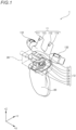
- FIG. 1 is a perspective view illustrating a first embodiment of the airway adaptor of the presently disclosed subject matter.
- the airway adaptor 1 may include a nasal expiration collecting portion 11, a gas sensor attaching portion 12, a first gas supplying portion 131, a second gas supplying portion 132, and an oral expiration collecting portion 20.
- the nasal expiration collecting portion 11 extends in the +Z and +Y directions.
- the nasal expiration collecting portion 11 is formed by a material in which the degree of influence on the human body is low, and which is soft and flexible, such as a silicone resin.
- the gas sensor attaching portion 12 is disposed below the nasal expiration collecting portion 11 in the -Z direction. As indicated by the dash-dot lines in FIG. 1 , a gas sensor 30 can be attached to the gas sensor attaching portion 12 from the front surface in the +Y direction.
- the first gas supplying portion 131 is disposed so as to extend in the -X direction with setting the position where the gas sensor attaching portion 12 of the airway adaptor 1 is disposed, as the center.
- the second gas supplying portion 132 is disposed so as to extend in the +X direction with setting the position where the gas sensor attaching portion 12 of the airway adaptor 1 is disposed, as the center.
- the oral expiration collecting portion 20 is disposed so as to extend in the -Z direction with setting the position where the gas sensor attaching portion 12 of the airway adaptor 1 is disposed, as the center. When the airway adaptor 1 is attached to the face of the human body, the oral expiration collecting portion 20 is located in front of the oral cavity, collects the expiration emitted from the mouth, and sends the collected expiration to the gas sensor attaching portion 12.
- FIG. 2 is a diagram of the airway adaptor 1 as viewed in the front direction. As illustrated in FIG. 2 , in the upper part of the gas sensor attaching portion 12, the nasal expiration collecting portion 11 branches off into a first nasal expiration collecting portion 111 and a second nasal expiration collecting portion 112.
- Each of the first and second nasal expiration collecting portions 111, 112 is configured by a fluid path having an approximately cylindrical shape.
- tip end portions of the first and second nasal expiration collecting portions 111, 112 are inserted into the two nostrils of the human body, respectively.
- the nasal expiration collecting portion 11 collects the expiration which is emitted from the nasal cavity of the human body, toward the gas sensor attaching portion 12.
- the nasal expiration collecting portion 11 may send gasses which are supplied from the first and second gas supplying portions 131, 132, to the nostrils of the human body.
- the first nasal expiration collecting portion 111 includes a first locked portion 113 in the vicinity of a tip end part of the front surface side.
- the second nasal expiration collecting portion 112 includes a second locked portion 114 in the vicinity of a tip end part of the front surface side. Both the first and second locked portions 113, 114 are configured by through holes which are formed in the first and second nasal expiration collecting portions 111, 112, respectively.
- the gas sensor attaching portion 12 may include a base portion 121, a gas sensor engaging portion 122, a magnet portion 123, gas sensor locking portions 124, gas sensor measurement windows 125, a first locking portion 127, and a second locking portion 128.
- the base portion 121 forms an approximate shape of the gas sensor attaching portion 12, and supports the nasal expiration collecting portion 11 which is disposed on the gas sensor attaching portion 12.
- the gas sensor engaging portion 122 is disposed so as to be engaged with the gas sensor 30.
- the gas sensor engaging portion 122 has a shape with which an engaged portion of the gas sensor 30 can be engaged.
- the gas sensor engaging portion 122 has a partition wall which separates the outer and inner sides from each other, on each of at least the front surface and the both side surfaces, thereby forming the gas passage portion, into which an expiration from the nasal expiration collecting portion 11 and the oral expiration collecting portion 20 flows, in the inner space.
- the magnet portion 123 can be contacted with a magnet portion which is disposed in the engaged portion of the gas sensor 30.
- the magnet portion 123 is disposed in, for example, the front-oriented surface of the gas sensor engaging portion 122.
- the magnet portion 123 is contacted with the magnet portion of the gas sensor 30 which is not illustrated, to prevent the gas sensor 30 from slipping off.
- the gas sensor locking portion 124 has a shape which, in order to allow locking with at least a part of the housing of the gas sensor 30, can receive a part of the housing of the gas sensor.
- the gas sensor measurement windows 125 are disposed so that the concentration of carbon dioxide of the gas in the gas passage portion formed in the gas sensor engaging portion 122 is measured by the gas sensor 30 which is attached to the gas sensor attaching portion 12. Therefore, the gas sensor measurement windows 125 are formed so that light emitted from the emitter of the gas sensor 30, and light propagating to the detector can pass through the respective windows.
- the gas sensor measurement windows 125 are windows in which, for example, a predetermined light transmittance is ensured.
- the gas sensor measurement windows 125 are disposed at respective positions which, when the gas sensor 30 is attached as illustrated in FIG. 1 , correspond to the positions of the emitter and the detector, such as the two opposing partition walls of the side surfaces forming the gas sensor engaging portion 122.
- FIG. 3 is a longitudinal sectional view illustrating the internal structure of the airway adaptor 1, as viewed in the right lateral direction.
- FIG. 3 illustrates sections of the first nasal expiration collecting portion 111, the gas sensor engaging portion 122, the gas passage portion 126, and the oral expiration collecting portion 20.
- the gas passage portion 126 is formed in the gas sensor engaging portion 122.
- the gas passage portion 126 is disposed inside the partition walls of the gas sensor engaging portion 122.
- the gas passage portion 126 functions as a gas passage for the expiration which is indicated by the arrow A1 in FIG.
- the expiration which is collected in the gas passage portion 126 is subjected to a measurement of CO 2 by the gas sensor 30 which is attached to the gas sensor engaging portion 122.
- the first locking portion 127 is disposed on the base portion 121.
- the first locking portion 127 is configured by a projection which is projected on the base portion 121.
- the first locking portion 127 is formed as a projection having a size which corresponds to the size of the hole of the first locked portion 113.
- the first locking portion 127 may be formed into a hook-like shape in order to maintain the locked state of the locked first locked portion 113.
- the second locking portion 128 is disposed on the base portion 121.
- the second locking portion 128 may be configured by a projection which is projected on the base portion 121, and have the size and shape which are same as or similar to those of the first locking portion 127.
- the gas supplying portion may include a first gas supplying portion 131, a second gas supplying portion 132, a first tube connecting portion 133, and a second tube connecting portion 134.
- the first gas supplying portion 131 is configured by a fluid path for supplying a gas to the nasal expiration collecting portion 11.
- the first gas supplying portion 131 is disposed on the left side as viewed toward the face of the human body.
- the second gas supplying portion 132 is configured by a fluid path for supplying a gas to the nasal expiration collecting portion 11.
- the second gas supplying portion 132 is disposed on the right side as viewed toward the face of the human body.
- the first tube connecting portion 133 is disposed in an end part of the first gas supplying portion 131.
- a tube which is not illustrated, and through which the gas is supplied can be connected to the first tube connecting portion 133.
- the first tube connecting portion 133 is configured by an opening which communicates with the first gas supplying portion 131.
- the gas which is supplied through the tube connected to the first tube connecting portion 133 is supplied to the nasal cavity of the human body from the nostril with passing through the nasal expiration collecting portion 11 from the first gas supplying portion 131.
- the second tube connecting portion 134 is disposed in an end part of the second gas supplying portion 132. In the same or similar manner as the first tube connecting portion 133, the tube through which the gas is supplied can be connected to the second tube connecting portion 134.
- the second tube connecting portion 134 is configured by an opening which communicates with the second gas supplying portion 132.
- the gas which is supplied through the tube connected to the second tube connecting portion 134 is supplied to the nasal cavity of the human body from the nostril with passing through the nasal expiration collecting portion 11 from the second gas supplying portion 132.
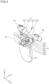
- FIG. 4 is a perspective view illustrating a manner of obstructing the first nasal expiration collecting portion 111 of the airway adaptor 1.
- FIG. 4 illustrates a manner in which the first nasal expiration collecting portion 111 of the nasal expiration collecting portion 11 is bent in the -Y direction, and the first locked portion 113 is locked to the first locking portion 127, thereby obstructing the first nasal expiration collecting portion 111.
- the nasal expiration collecting portion 11 is formed by a flexible material.
- the first locked portion 113 is disposed in the first nasal expiration collecting portion 111
- the second locked portion 114 is disposed in the second nasal expiration collecting portion 112.
- the first and second locking portions 127, 128 are disposed in the base portion 121 of the gas sensor attaching portion 12 which is on the front side.
- the first locked portion 113 is locked to the first locking portion 127
- the second locked portion 114 is locked to the second locking portion 128, thereby the first and second nasal expiration collecting portions 111, 112 which are formed by a soft and flexible member are bent.
- the flow paths of the first and second nasal expiration collecting portions 111, 112 are collapsed, and the states of the flow paths are changed from the flowing state where the flow of the expiration is allowed, to the obstruction state where the flow of the expiration is blocked.
- the first and second locked portions 113, 114 function as the obstruction state producing portion which causes the first nasal expiration collecting portion 111 to be obstructable.
- the first and second locking portions 127, 128 function as the obstruction state producing portion which causes the second nasal expiration collecting portion 112 to be obstructable.
- the first and second nasal expiration collecting portions 111, 112 of the nasal expiration collecting portion 11 can show the flowing state where the flow of the expiration is allowed, and the obstruction state where the flow of the expiration is blocked.
- FIG. 5 is a diagram illustrating a state where the airway adaptor 1 is attached to the human body H.
- the airway adaptor 1 in such a case where, when the adaptor is attached to the human body H, a tool for a transnasal endoscopic surgical procedure is to be inserted through one nostril NH1 as illustrated in FIG. 5 , the first locked portion 113 is locked to the first locking portion 127, thereby the first nasal expiration collecting portion 111 can be obstructed.
- the nasal expiration collecting portion 11 when a tool is to be inserted into the nostril NH1, as described above, the nasal expiration collecting portion 11 can be prevented from impeding the implementation of techniques, and the adaptability to the techniques can be improved.
- the airway adaptor 1 which can be used in this way, even under circumstances where a liquid such as snivel or medicine drips from the nostril NH1, the first nasal expiration collecting portion 111 can be obstructed. Therefore, it is possible to prevent a situation where a liquid enters the gas passage portion 126 to cause the gas sensor 30 to malfunction, from occurring.
- the positions where the first and second locked portions 113, 114 are respectively disposed are not limited to the above-described ones.
- the first and second locked portions 113, 114 are requested only to lock the flexible nasal expiration collecting portion 11 to maintain the bent state, so that the nasal expiration collecting portion 11 is obstructed.
- the gas supplying portion is not limited to have the configuration where two portions are laterally separated as viewed toward the face of the human body, such as in the case of the first and second gas supplying portions 131, 132.
- the gas supplying portion may have a configuration where the gas is suppled through a tube which is connected to one tube connecting portion.
- FIG. 6 is a perspective view illustrating the second embodiment of the airway adaptor of the presently disclosed subject matter.
- the configurations of a nasal expiration collecting portion 11A and a gas sensor attaching portion 12A are different from those of the nasal expiration collecting portion 11 and gas sensor attaching portion 12 of the above-described airway adaptor 1.
- a first nasal expiration collecting portion 111A and a second nasal expiration collecting portion 112A are formed so as to be detachable from the airway adaptor 1.
- FIG. 6 illustrates a state where only the second nasal expiration collecting portion 112A is detached from the airway adaptor 1.
- the first and second nasal expiration collecting portions 111A, 112A are attached onto a tubular attached portion 129 which is disposed in a base portion 121A of the gas sensor attaching portion 12A, thereby the nasal expiration collecting portions are attached to the airway adaptor 1A.
- a lid 115 which functions as the obstruction state producing portion is attached to the attached portion 129 from which the first nasal expiration collecting portion 111A or the second nasal expiration collecting portion 112A is detached, so that the gas passage of the corresponding nasal expiration collecting portion can be obstructed.
- the first nasal expiration collecting portion 111A or the second nasal expiration collecting portion 112A is detached, and the resulting opening is closed by the lid 115, thereby the nasal expiration collecting portion 11A can be prevented from impeding the implementation of techniques such as insertion of a tool into the other nostril. According to the airway adaptor 1A, therefore, the adaptabilities to the techniques can be improved.
- FIG. 7 is a perspective view illustrating the third embodiment of the airway adaptor of the presently disclosed subject matter.
- the configurations of a nasal expiration collecting portion 11B and a gas sensor attaching portion 12B are different from those of the nasal expiration collecting portion 11 and gas sensor attaching portion 12 of the above-described airway adaptor 1.
- the nasal expiration collecting portion 11B may include one tubular part which can be inserted into the nostril.
- the nasal expiration collecting portion 11B is configured so as to swing about the Z direction with respect to a base portion 121B of the gas sensor attaching portion 12B. As illustrated in FIG. 7 , therefore, the nasal expiration collecting portion 11B may be deviated to the left side as opposed to the human body so as to be easily inserted into the right nostril of the human body.
- FIG. 8 is a perspective view illustrating another mode of the airway adaptor 1B.
- the nasal expiration collecting portion 11B When the nasal expiration collecting portion 11B is swung with respect to the base portion 121B, the nasal expiration collecting portion 11B may be deviated to the right side as opposed to the human body as illustrated in FIG. 8 so as to be easily inserted into the left nostril of the human body.
- FIGS. 7 and 8 illustrate the examples in which the whole nasal expiration collecting portion 11B including the gas supplying portion is swung with respect to the base portion 121B
- the nasal expiration collecting portion 11B may be configured so that only the portion which connects the cylindrical part that is to be inserted into the nostril, to the gas passage portion 126 can be swung, and the gas supplying portion cannot be swung.
- the one nasal expiration collecting portion 11B is deviated to the side of the one nostril, thereby the nasal expiration collecting portion 11B can be prevented from impeding the implementation of techniques such as insertion of a tool into the other nostril, and the adaptabilities to the techniques can be improved.
- FIG. 9 is a perspective view illustrating the fourth embodiment of the airway adaptor of the presently disclosed subject matter.
- the configuration of a nasal expiration collecting portion 11C is different from that of the nasal expiration collecting portion 11 of the above-described airway adaptor 1.
- the nasal expiration collecting portion 11C may include one tubular part which can be inserted into the nostril.
- the nasal expiration collecting portion 11C is inserted into one of the two nostrils. No technique is applied to the one nostril.
- the nasal expiration collecting portion 11C may be larger in tube length than the above-described nasal expiration collecting portion 11 and the like.
- the one nasal expiration collecting portion 11C is inserted into one of the nostrils, thereby the nasal expiration collecting portion 11C can be prevented from impeding the implementation of technique such as insertion of a tool into the other nostril, and the adaptabilities to the techniques can be improved.
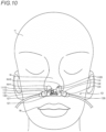
- FIG. 10 is a diagram illustrating the embodiment of the nasal cannula 1D of the presently disclosed subject matter, in a state where the nasal cannula 1D is attached to the human body H.
- the nasal cannula 1D includes a first nostril connecting portion 111D, a second nostril connecting portion 112D, the first locked portion 113, the second locked portion 114, the base portion 121, the first locking portion 127, the second locking portion 128, the first gas supplying portion 131, and the second gas supplying portion 132.
- the first nostril connecting portion 111D is connected to the left nostril NH1 of the human body H to supply the gas to the nasal cavity.
- the second nostril connecting portion 112D is connected to the right nostril NH2 of the human body H to supply the gas to the nasal cavity.
- the configuration of the first nostril connecting portion 111D, including the disposition of the first locked portion 113 which is lockable to the first locking portion 127 is same as or similar to that of the above-described first nostril connecting portion 111.
- the configuration of the second nostril connecting portion 112D, including the disposition of the second locked portion 114 which is lockable to the second locking portion 128 is same as or similar to that of the above-described second nostril connecting portion 112.
- the base portion 121 forms an approximate shape of the nasal cannula 1D.
- the base portion 121 supports the nostril connecting portion having the first and second nostril connecting portion 111D, 112D, and the gas supplying portion having the first and second gas supplying portions 131, 132.
- the first and second locking portions 127, 128 are configured by projections which are projected on the base portion 121, respectively, in the same or similar manner as the first and second locking portions 127, 128 of the above-described airway adaptor 1.
- the first gas supplying portion 131 supplies the gas to the first nostril connecting portion 111D.
- the second gas supplying portion 132 supplies the gas to the second nostril connecting portion 112D.
- the nasal cannula 1D in the same or similar manner as the airway adaptor 1, in such a case where, when the cannula is attached to the human body H, a tool for a transnasal endoscopic surgical procedure is to be inserted through one nostril NH1 as illustrated in FIG. 10 , the first locking portion 127 can be locked to the first locked portion 113. According to the nasal cannula 1D, therefore, the first nostril connecting portion 111D can be obstructed in the same or similar manner as the airway adaptor 1 which includes the first locking portion 127 and the first locked portion 113.
- the second locking portion 128 can be locked to the second locked portion 114.
- the nasal cannula 1D namely, the first nostril connecting portion 111D and the first locking portion 127, and the second nostril connecting portion 112D and the second locking portion 128 function as the obstruction state producing portion which causes the corresponding nostril connecting portion formed by a flexible member, to be bent, thereby obstructing the nostril connecting portion.
- the second nostril connecting portion 112D can be obstructed in the same or similar manner as the airway adaptor 1 including the second locking portion 128 and the second locked portion 114.
- the nasal cannula 1D when a tool is to be inserted into the nostril NH1 or NH2, as described above, the first nostril connecting portion 111D or the second nostril connecting portion 112D can be prevented from impeding the implementation of techniques, and the adaptability to the techniques can be improved.
Landscapes
- Health & Medical Sciences (AREA)
- Life Sciences & Earth Sciences (AREA)
- Pulmonology (AREA)
- General Health & Medical Sciences (AREA)
- Veterinary Medicine (AREA)
- Biomedical Technology (AREA)
- Heart & Thoracic Surgery (AREA)
- Public Health (AREA)
- Engineering & Computer Science (AREA)
- Animal Behavior & Ethology (AREA)
- Emergency Medicine (AREA)
- Hematology (AREA)
- Anesthesiology (AREA)
- Physiology (AREA)
- Physics & Mathematics (AREA)
- Biophysics (AREA)
- Pathology (AREA)
- Medical Informatics (AREA)
- Molecular Biology (AREA)
- Surgery (AREA)
- Otolaryngology (AREA)
- Measurement Of The Respiration, Hearing Ability, Form, And Blood Characteristics Of Living Organisms (AREA)
Claims (7)
- Ein Atemwegadapter (1), aufweisend:einen nasalen Exspirations-Sammelabschnitt (11), der mit einem Nasenloch eines lebenden Körpers zu verbinden ist und der konfiguriert ist, um eine Exspiration einer Nasenhöhle zu sammeln;einen Gasdurchlassabschnitt (126), der einen Gasdurchlass bildet, durch den die von dem nasalen Exspirations-Sammelabschnitt (11) gesammelte Ausatmung hindurchgeht; undeinen Gassensor-Befestigungsabschnitt (12), der so konfiguriert ist, dass er einen Gassensor in dem Gasdurchlassabschnitt (126) befestigt,wobei der nasale Exspirations-Sammelabschnitt (11) so konfiguriert ist, dass er einen fließenden Zustand, in dem ein Fluss der Exspiration erlaubt ist, und einen Blockierungszustand, in dem der Fluss der Exspiration blockiert ist, erzeugt,wobei der nasale Exspirations-Sammelabschnitt (11) durch ein flexibles Element gebildet ist und einen Obstruktionszustand erzeugenden Abschnitt enthält, der bewirkt, dass der nasale Exspirations-Sammelabschnitt obstruierbar ist, wobei der nasale Exspirations-Sammelabschnitt (11) so konfiguriert ist, dass er gebogen werden kann, um den nasalen Exspirations-Sammelabschnitt (11) zu obstruieren,wobei der den Obstruktionszustand erzeugende Abschnitt umfasst:einen verriegelten Abschnitt (113, 114), der in dem nasalen Exspirations-Sammelabschnitt (11) angeordnet ist; undeinen Verriegelungsabschnitt (127, 128), der mit dem verriegelten Abschnitt in Eingriff zu bringen ist, um einen Zustand aufrechtzuerhalten, in dem der nasale Exspirations-Sammelabschnitt (11) gebogen ist; undwobei der verriegelte Abschnitt ein Loch ist, das in dem nasalen Exspirations-Sammelabschnitt (11) ausgebildet ist, undder Verriegelungsabschnitt ein Vorsprung ist, der auf dem nasalen Exspirations-Sammelabschnitt (11) oder dem Gassensor-Befestigungsabschnitt (12) ausgebildet ist.
- Der Atemwegadapter (1) nach Anspruch 1, wobei
der nasale Exspirations-Sammelabschnitt (11) umfasst:einen ersten nasalen Exspirations-Sammelabschnitt (111), der mit einem Nasenloch des lebenden Körpers zu verbinden ist, um einen Gasdurchgang für die Ausatmung der Nasenhöhle zu bilden; undeinen zweiten nasalen Exspirations-Sammelabschnitt (112), der mit einem anderen Nasenloch des lebenden Körpers zu verbinden ist, um einen Gasdurchlass für die Exspiration der Nasenhöhle zu bilden. - Der Atemwegadapter (1) nach Anspruch 1, der ferner einen oralen Exspirations-Sammelabschnitt umfasst, der mit einer Mundhöhle des lebenden Körpers zu verbinden ist, um eine Ausatmung der Mundhöhle zu sammeln,
wobei der Gasdurchlassabschnitt (126) eine Exspiration von dem nasalen Exspirations-sammelabschnitt (11) und dem oralen Exspirations-Sammelabschnitt sammelt. - Der Atemwegadapter (1) nach Anspruch 1, der ferner einen Gaszuführungsabschnitt umfasst, der dem nasalen Exspirations-Sammelabschnitt (11) ein Gas zuführt.
- Der Atemwegadapter (1) nach Anspruch 1, wobeider Gasdurchlassabschnitt (126) eine Trennwand aufweist, die Außen- und Innenseiten des Gasdurchlassabschnitt (126) voneinander trennt, undder Gassensor-Befestigungsabschnitt (12) Gassensor-Messfenster enthält, die in zwei gegenüberliegenden Oberflächen der Trennwand des Gasdurchlassabschnitts (126) angeordnet sind und die eine vorbestimmte Lichtdurchlässigkeit aufweisen.
- Eine Nasenkanüle (1D), umfassend:einen Nasenloch-Verbindungsabschnitt (111D, 112D), der mit einem Nasenloch eines lebenden Körpers zu verbinden ist und der so konfiguriert ist, dass er einer Nasenhöhle ein Gas zuführt,wobei der Nasenloch-Verbindungsabschnitt (111D, 112D) einen fließenden Zustand, in dem ein Fluss des Gases erlaubt ist, und einen Blockierungszustand, in dem der Fluss des Gases blockiert ist, erzeugt,wobei der Nasenloch-Verbindungsabschnitt (111D, 112D) durch ein flexibles Element gebildet ist und einen Blockierungszustand erzeugenden Abschnitt enthält, der bewirkt, dass der nasale Ausatmungssammelabschnitt blockierbar ist, wobei der Nasenloch-Verbindungsabschnitt (111D, 112D) so konfiguriert ist, dass er gebogen werden kann, um den Nasenloch-Verbindungsabschnitt (111D, 112D) zu blockieren,wobei der Blockierungszustand erzeugende Abschnitt umfasst:einen verriegelten Abschnitt (113, 114), der in dem Nasenlochverbindungsabschnitt (111D, 112D) angeordnet ist; undeinen Verriegelungsabschnitt (127, 128), der mit dem verriegelten Abschnitt in Eingriff zu bringen ist, um einen Zustand aufrechtzuerhalten, in dem der Nasenlochverbindungsabschnitt (111D, 112D) gebogen ist,wobei die Nasenkanüle (1D) ferner einen Basisabschnitt umfasst, der den Nasenloch-Verbindungsabschnitt (111D, 112D) stützt,dadurch gekennzeichnet, dassder verriegelte Abschnitt ein Loch ist, das in dem Nasenloch-Verbindungsabschnitt (111D, 112D) ausgebildet ist, undder Verriegelungsabschnitt ein Vorsprung ist, der an dem Basisabschnitt ausgebildet ist.
- Die Nasenkanüle (1D) nach Anspruch 6, wobei
der Nasenloch-Verbindungsabschnitt (111D, 112D) umfasst:einen ersten Nasenlochverbindungsabschnitt (111D), der mit einem Nasenloch des lebenden Körpers zu verbinden ist; undeinen zweiten Nasenlochverbindungsabschnitt (112D), der mit einem anderen Nasenloch des lebenden Körpers zu verbinden ist.
Applications Claiming Priority (2)
| Application Number | Priority Date | Filing Date | Title |
|---|---|---|---|
| JP2018064937 | 2018-03-29 | ||
| JP2018218145A JP7235483B2 (ja) | 2018-03-29 | 2018-11-21 | エアウェイアダプタ、鼻カニューラ |
Publications (2)
| Publication Number | Publication Date |
|---|---|
| EP3546005A1 EP3546005A1 (de) | 2019-10-02 |
| EP3546005B1 true EP3546005B1 (de) | 2024-11-06 |
Family
ID=65812161
Family Applications (1)
| Application Number | Title | Priority Date | Filing Date |
|---|---|---|---|
| EP19162754.6A Active EP3546005B1 (de) | 2018-03-29 | 2019-03-14 | Atemwegsadapter und nasenkanüle |
Country Status (2)
| Country | Link |
|---|---|
| US (1) | US11717632B2 (de) |
| EP (1) | EP3546005B1 (de) |
Families Citing this family (5)
| Publication number | Priority date | Publication date | Assignee | Title |
|---|---|---|---|---|
| WO2023026203A1 (en) * | 2021-08-25 | 2023-03-02 | Fisher & Paykel Healthcare Limited | Patient interface gas sampling and accessory for patient interface |
| US20250255484A1 (en) * | 2022-04-16 | 2025-08-14 | The General Hospital Corporation | Materials and methods for luminescence-based carbon dioxide sensing |
| CN114887172B (zh) * | 2022-05-20 | 2025-02-21 | 王宇 | 新生儿临床用呼吸机 |
| WO2024263079A1 (en) | 2023-06-20 | 2024-12-26 | Oxlantic Medical Ab | Mainstream capnography |
| EP4731074A1 (de) | 2023-06-20 | 2026-04-29 | Oxlantic Medical AB | Somnografiesystem |
Citations (1)
| Publication number | Priority date | Publication date | Assignee | Title |
|---|---|---|---|---|
| US20180064898A1 (en) * | 2015-03-31 | 2018-03-08 | Fisher & Paykel Healthcare Limited | Nasal cannula |
Family Cites Families (7)
| Publication number | Priority date | Publication date | Assignee | Title |
|---|---|---|---|---|
| US7640932B2 (en) | 1997-04-29 | 2010-01-05 | Salter Labs | Nasal cannula for acquiring breathing information |
| JP4247758B2 (ja) | 2003-02-18 | 2009-04-02 | 日本光電工業株式会社 | 炭酸ガス測定センサ |
| US8161971B2 (en) | 2006-08-04 | 2012-04-24 | Ric Investments, Llc | Nasal and oral patient interface |
| JP5666177B2 (ja) | 2010-06-29 | 2015-02-12 | 株式会社医器研 | 過熱検知アダプタユニットおよび酸素濃縮装置 |
| JP6137823B2 (ja) | 2012-09-04 | 2017-05-31 | 日本光電工業株式会社 | エアウェイアダプタ、生体情報取得システムおよび酸素マスク |
| WO2014143847A1 (en) | 2013-03-15 | 2014-09-18 | Salter Labs | Method and system with divided cannula having low oxygen flow rate and improved end-tidal co2 measurement |
| KR20240157114A (ko) * | 2016-08-11 | 2024-10-31 | 피셔 앤 페이켈 핼스케어 리미티드 | 압궤 가능 도관, 환자 인터페이스 및 헤드기어 연결부 |
-
2019
- 2019-03-13 US US16/352,118 patent/US11717632B2/en active Active
- 2019-03-14 EP EP19162754.6A patent/EP3546005B1/de active Active
Patent Citations (1)
| Publication number | Priority date | Publication date | Assignee | Title |
|---|---|---|---|---|
| US20180064898A1 (en) * | 2015-03-31 | 2018-03-08 | Fisher & Paykel Healthcare Limited | Nasal cannula |
Also Published As
| Publication number | Publication date |
|---|---|
| US11717632B2 (en) | 2023-08-08 |
| US20190298960A1 (en) | 2019-10-03 |
| EP3546005A1 (de) | 2019-10-02 |
Similar Documents
| Publication | Publication Date | Title |
|---|---|---|
| EP3546005B1 (de) | Atemwegsadapter und nasenkanüle | |
| EP2753392B1 (de) | Sauerstoffgesichtsmaske mit kapnografieüberwachungs-ports | |
| JP4968647B2 (ja) | 呼気情報収集用アダプタおよび生体情報処理システム | |
| US10188818B2 (en) | Respiratory mask | |
| US20120283513A1 (en) | Oral airway devices and methods for making and using them | |
| EP2275031B1 (de) | Atemwegsadapter für die Leitung der ausgeatmeten Gase in einen Analysator | |
| CN101557782A (zh) | 带有呼吸气体测量部件的病人界面装置 | |
| JP6858134B2 (ja) | 患者インターフェースアセンブリにおける液体除去 | |
| EP3468442B1 (de) | Beissring und gassensor kit | |
| JP7235483B2 (ja) | エアウェイアダプタ、鼻カニューラ | |
| EP3546006B1 (de) | Atmungsunterstützungsvorrichtung | |
| US20240009414A1 (en) | Airway device | |
| US11576591B2 (en) | Gas sensor kit and gas supply unit | |
| JP6875797B2 (ja) | ガスセンサキット及び顔面装着具 | |
| US20230371844A1 (en) | Apparatus and method for measuring end tidal carbon dioxide (etco2) | |
| US20250090782A1 (en) | Nasal Cannula Assembly | |
| JP2021520242A (ja) | カプノグラフィーモジュールに関するアクセサリー検出 | |
| GB2634633A (en) | Nasal cannula assembly | |
| CN120132170A (zh) | 一种应用于多场景的硬质气管镜鞘 |
Legal Events
| Date | Code | Title | Description |
|---|---|---|---|
| PUAI | Public reference made under article 153(3) epc to a published international application that has entered the european phase |
Free format text: ORIGINAL CODE: 0009012 |
|
| STAA | Information on the status of an ep patent application or granted ep patent |
Free format text: STATUS: THE APPLICATION HAS BEEN PUBLISHED |
|
| AK | Designated contracting states |
Kind code of ref document: A1 Designated state(s): AL AT BE BG CH CY CZ DE DK EE ES FI FR GB GR HR HU IE IS IT LI LT LU LV MC MK MT NL NO PL PT RO RS SE SI SK SM TR |
|
| AX | Request for extension of the european patent |
Extension state: BA ME |
|
| STAA | Information on the status of an ep patent application or granted ep patent |
Free format text: STATUS: REQUEST FOR EXAMINATION WAS MADE |
|
| 17P | Request for examination filed |
Effective date: 20200312 |
|
| RBV | Designated contracting states (corrected) |
Designated state(s): AL AT BE BG CH CY CZ DE DK EE ES FI FR GB GR HR HU IE IS IT LI LT LU LV MC MK MT NL NO PL PT RO RS SE SI SK SM TR |
|
| STAA | Information on the status of an ep patent application or granted ep patent |
Free format text: STATUS: EXAMINATION IS IN PROGRESS |
|
| 17Q | First examination report despatched |
Effective date: 20221223 |
|
| REG | Reference to a national code |
Ref country code: DE Ref legal event code: R079 Ref country code: DE Ref legal event code: R079 Ref document number: 602019061385 Country of ref document: DE Free format text: PREVIOUS MAIN CLASS: A61M0016060000 Ipc: A61B0005080000 |
|
| GRAP | Despatch of communication of intention to grant a patent |
Free format text: ORIGINAL CODE: EPIDOSNIGR1 |
|
| STAA | Information on the status of an ep patent application or granted ep patent |
Free format text: STATUS: GRANT OF PATENT IS INTENDED |
|
| RIC1 | Information provided on ipc code assigned before grant |
Ipc: A61B 5/00 20060101ALN20240531BHEP Ipc: A61B 5/083 20060101ALN20240531BHEP Ipc: A61M 16/08 20060101ALI20240531BHEP Ipc: A61M 16/06 20060101ALI20240531BHEP Ipc: A61B 5/097 20060101ALI20240531BHEP Ipc: A61B 5/08 20060101AFI20240531BHEP |
|
| INTG | Intention to grant announced |
Effective date: 20240625 |
|
| GRAS | Grant fee paid |
Free format text: ORIGINAL CODE: EPIDOSNIGR3 |
|
| GRAA | (expected) grant |
Free format text: ORIGINAL CODE: 0009210 |
|
| STAA | Information on the status of an ep patent application or granted ep patent |
Free format text: STATUS: THE PATENT HAS BEEN GRANTED |
|
| AK | Designated contracting states |
Kind code of ref document: B1 Designated state(s): AL AT BE BG CH CY CZ DE DK EE ES FI FR GB GR HR HU IE IS IT LI LT LU LV MC MK MT NL NO PL PT RO RS SE SI SK SM TR |
|
| REG | Reference to a national code |
Ref country code: GB Ref legal event code: FG4D |
|
| REG | Reference to a national code |
Ref country code: CH Ref legal event code: EP |
|
| REG | Reference to a national code |
Ref country code: DE Ref legal event code: R096 Ref document number: 602019061385 Country of ref document: DE |
|
| REG | Reference to a national code |
Ref country code: IE Ref legal event code: FG4D |
|
| REG | Reference to a national code |
Ref country code: LT Ref legal event code: MG9D |
|
| REG | Reference to a national code |
Ref country code: NL Ref legal event code: MP Effective date: 20241106 |
|
| PG25 | Lapsed in a contracting state [announced via postgrant information from national office to epo] |
Ref country code: HR Free format text: LAPSE BECAUSE OF FAILURE TO SUBMIT A TRANSLATION OF THE DESCRIPTION OR TO PAY THE FEE WITHIN THE PRESCRIBED TIME-LIMIT Effective date: 20241106 Ref country code: PT Free format text: LAPSE BECAUSE OF FAILURE TO SUBMIT A TRANSLATION OF THE DESCRIPTION OR TO PAY THE FEE WITHIN THE PRESCRIBED TIME-LIMIT Effective date: 20250306 Ref country code: IS Free format text: LAPSE BECAUSE OF FAILURE TO SUBMIT A TRANSLATION OF THE DESCRIPTION OR TO PAY THE FEE WITHIN THE PRESCRIBED TIME-LIMIT Effective date: 20250306 |
|
| PG25 | Lapsed in a contracting state [announced via postgrant information from national office to epo] |
Ref country code: NL Free format text: LAPSE BECAUSE OF FAILURE TO SUBMIT A TRANSLATION OF THE DESCRIPTION OR TO PAY THE FEE WITHIN THE PRESCRIBED TIME-LIMIT Effective date: 20241106 Ref country code: FI Free format text: LAPSE BECAUSE OF FAILURE TO SUBMIT A TRANSLATION OF THE DESCRIPTION OR TO PAY THE FEE WITHIN THE PRESCRIBED TIME-LIMIT Effective date: 20241106 |
|
| REG | Reference to a national code |
Ref country code: AT Ref legal event code: MK05 Ref document number: 1738457 Country of ref document: AT Kind code of ref document: T Effective date: 20241106 |
|
| PG25 | Lapsed in a contracting state [announced via postgrant information from national office to epo] |
Ref country code: BG Free format text: LAPSE BECAUSE OF FAILURE TO SUBMIT A TRANSLATION OF THE DESCRIPTION OR TO PAY THE FEE WITHIN THE PRESCRIBED TIME-LIMIT Effective date: 20241106 |
|
| PG25 | Lapsed in a contracting state [announced via postgrant information from national office to epo] |
Ref country code: ES Free format text: LAPSE BECAUSE OF FAILURE TO SUBMIT A TRANSLATION OF THE DESCRIPTION OR TO PAY THE FEE WITHIN THE PRESCRIBED TIME-LIMIT Effective date: 20241106 |
|
| PG25 | Lapsed in a contracting state [announced via postgrant information from national office to epo] |
Ref country code: NO Free format text: LAPSE BECAUSE OF FAILURE TO SUBMIT A TRANSLATION OF THE DESCRIPTION OR TO PAY THE FEE WITHIN THE PRESCRIBED TIME-LIMIT Effective date: 20250206 |
|
| PG25 | Lapsed in a contracting state [announced via postgrant information from national office to epo] |
Ref country code: GR Free format text: LAPSE BECAUSE OF FAILURE TO SUBMIT A TRANSLATION OF THE DESCRIPTION OR TO PAY THE FEE WITHIN THE PRESCRIBED TIME-LIMIT Effective date: 20250207 Ref country code: AT Free format text: LAPSE BECAUSE OF FAILURE TO SUBMIT A TRANSLATION OF THE DESCRIPTION OR TO PAY THE FEE WITHIN THE PRESCRIBED TIME-LIMIT Effective date: 20241106 Ref country code: LV Free format text: LAPSE BECAUSE OF FAILURE TO SUBMIT A TRANSLATION OF THE DESCRIPTION OR TO PAY THE FEE WITHIN THE PRESCRIBED TIME-LIMIT Effective date: 20241106 |
|
| PG25 | Lapsed in a contracting state [announced via postgrant information from national office to epo] |
Ref country code: PL Free format text: LAPSE BECAUSE OF FAILURE TO SUBMIT A TRANSLATION OF THE DESCRIPTION OR TO PAY THE FEE WITHIN THE PRESCRIBED TIME-LIMIT Effective date: 20241106 |
|
| PG25 | Lapsed in a contracting state [announced via postgrant information from national office to epo] |
Ref country code: RS Free format text: LAPSE BECAUSE OF FAILURE TO SUBMIT A TRANSLATION OF THE DESCRIPTION OR TO PAY THE FEE WITHIN THE PRESCRIBED TIME-LIMIT Effective date: 20250206 |
|
| PG25 | Lapsed in a contracting state [announced via postgrant information from national office to epo] |
Ref country code: SM Free format text: LAPSE BECAUSE OF FAILURE TO SUBMIT A TRANSLATION OF THE DESCRIPTION OR TO PAY THE FEE WITHIN THE PRESCRIBED TIME-LIMIT Effective date: 20241106 |
|
| PG25 | Lapsed in a contracting state [announced via postgrant information from national office to epo] |
Ref country code: DK Free format text: LAPSE BECAUSE OF FAILURE TO SUBMIT A TRANSLATION OF THE DESCRIPTION OR TO PAY THE FEE WITHIN THE PRESCRIBED TIME-LIMIT Effective date: 20241106 |
|
| PG25 | Lapsed in a contracting state [announced via postgrant information from national office to epo] |
Ref country code: EE Free format text: LAPSE BECAUSE OF FAILURE TO SUBMIT A TRANSLATION OF THE DESCRIPTION OR TO PAY THE FEE WITHIN THE PRESCRIBED TIME-LIMIT Effective date: 20241106 |
|
| PG25 | Lapsed in a contracting state [announced via postgrant information from national office to epo] |
Ref country code: RO Free format text: LAPSE BECAUSE OF FAILURE TO SUBMIT A TRANSLATION OF THE DESCRIPTION OR TO PAY THE FEE WITHIN THE PRESCRIBED TIME-LIMIT Effective date: 20241106 |
|
| PG25 | Lapsed in a contracting state [announced via postgrant information from national office to epo] |
Ref country code: SK Free format text: LAPSE BECAUSE OF FAILURE TO SUBMIT A TRANSLATION OF THE DESCRIPTION OR TO PAY THE FEE WITHIN THE PRESCRIBED TIME-LIMIT Effective date: 20241106 |
|
| PG25 | Lapsed in a contracting state [announced via postgrant information from national office to epo] |
Ref country code: CZ Free format text: LAPSE BECAUSE OF FAILURE TO SUBMIT A TRANSLATION OF THE DESCRIPTION OR TO PAY THE FEE WITHIN THE PRESCRIBED TIME-LIMIT Effective date: 20241106 |
|
| PG25 | Lapsed in a contracting state [announced via postgrant information from national office to epo] |
Ref country code: IT Free format text: LAPSE BECAUSE OF FAILURE TO SUBMIT A TRANSLATION OF THE DESCRIPTION OR TO PAY THE FEE WITHIN THE PRESCRIBED TIME-LIMIT Effective date: 20241106 |
|
| REG | Reference to a national code |
Ref country code: DE Ref legal event code: R097 Ref document number: 602019061385 Country of ref document: DE |
|
| PG25 | Lapsed in a contracting state [announced via postgrant information from national office to epo] |
Ref country code: SE Free format text: LAPSE BECAUSE OF FAILURE TO SUBMIT A TRANSLATION OF THE DESCRIPTION OR TO PAY THE FEE WITHIN THE PRESCRIBED TIME-LIMIT Effective date: 20241106 |
|
| PLBE | No opposition filed within time limit |
Free format text: ORIGINAL CODE: 0009261 |
|
| STAA | Information on the status of an ep patent application or granted ep patent |
Free format text: STATUS: NO OPPOSITION FILED WITHIN TIME LIMIT |
|
| PG25 | Lapsed in a contracting state [announced via postgrant information from national office to epo] |
Ref country code: MC Free format text: LAPSE BECAUSE OF FAILURE TO SUBMIT A TRANSLATION OF THE DESCRIPTION OR TO PAY THE FEE WITHIN THE PRESCRIBED TIME-LIMIT Effective date: 20241106 |
|
| 26N | No opposition filed |
Effective date: 20250807 |
|
| REG | Reference to a national code |
Ref country code: CH Ref legal event code: H13 Free format text: ST27 STATUS EVENT CODE: U-0-0-H10-H13 (AS PROVIDED BY THE NATIONAL OFFICE) Effective date: 20251024 |
|
| PG25 | Lapsed in a contracting state [announced via postgrant information from national office to epo] |
Ref country code: LU Free format text: LAPSE BECAUSE OF NON-PAYMENT OF DUE FEES Effective date: 20250314 |
|
| GBPC | Gb: european patent ceased through non-payment of renewal fee |
Effective date: 20250314 |
|
| REG | Reference to a national code |
Ref country code: BE Ref legal event code: MM Effective date: 20250331 |
|
| PG25 | Lapsed in a contracting state [announced via postgrant information from national office to epo] |
Ref country code: GB Free format text: LAPSE BECAUSE OF NON-PAYMENT OF DUE FEES Effective date: 20250314 |
|
| PG25 | Lapsed in a contracting state [announced via postgrant information from national office to epo] |
Ref country code: FR Free format text: LAPSE BECAUSE OF NON-PAYMENT OF DUE FEES Effective date: 20250331 |
|
| PG25 | Lapsed in a contracting state [announced via postgrant information from national office to epo] |
Ref country code: BE Free format text: LAPSE BECAUSE OF NON-PAYMENT OF DUE FEES Effective date: 20250331 |
|
| PG25 | Lapsed in a contracting state [announced via postgrant information from national office to epo] |
Ref country code: CH Free format text: LAPSE BECAUSE OF NON-PAYMENT OF DUE FEES Effective date: 20250331 |
|
| PG25 | Lapsed in a contracting state [announced via postgrant information from national office to epo] |
Ref country code: IE Free format text: LAPSE BECAUSE OF NON-PAYMENT OF DUE FEES Effective date: 20250314 |
|
| PGFP | Annual fee paid to national office [announced via postgrant information from national office to epo] |
Ref country code: DE Payment date: 20260128 Year of fee payment: 8 |