EP3546104B1 - Système d'alimentation en fil de soudage - Google Patents
Système d'alimentation en fil de soudage Download PDFInfo
- Publication number
- EP3546104B1 EP3546104B1 EP19164583.7A EP19164583A EP3546104B1 EP 3546104 B1 EP3546104 B1 EP 3546104B1 EP 19164583 A EP19164583 A EP 19164583A EP 3546104 B1 EP3546104 B1 EP 3546104B1
- Authority
- EP
- European Patent Office
- Prior art keywords
- welding
- rod
- welding rod
- unit
- welding wire
- Prior art date
- Legal status (The legal status is an assumption and is not a legal conclusion. Google has not performed a legal analysis and makes no representation as to the accuracy of the status listed.)
- Active
Links
Images

Classifications
-
- B—PERFORMING OPERATIONS; TRANSPORTING
- B23—MACHINE TOOLS; METAL-WORKING NOT OTHERWISE PROVIDED FOR
- B23K—SOLDERING OR UNSOLDERING; WELDING; CLADDING OR PLATING BY SOLDERING OR WELDING; CUTTING BY APPLYING HEAT LOCALLY, e.g. FLAME CUTTING; WORKING BY LASER BEAM
- B23K9/00—Arc welding or cutting
- B23K9/12—Automatic feeding or moving of electrodes or work for spot or seam welding or cutting
- B23K9/122—Devices for guiding electrodes, e.g. guide tubes
-
- B—PERFORMING OPERATIONS; TRANSPORTING
- B23—MACHINE TOOLS; METAL-WORKING NOT OTHERWISE PROVIDED FOR
- B23K—SOLDERING OR UNSOLDERING; WELDING; CLADDING OR PLATING BY SOLDERING OR WELDING; CUTTING BY APPLYING HEAT LOCALLY, e.g. FLAME CUTTING; WORKING BY LASER BEAM
- B23K37/00—Auxiliary devices or processes, not specially adapted for a procedure covered by only one of the other main groups of this subclass
-
- B—PERFORMING OPERATIONS; TRANSPORTING
- B23—MACHINE TOOLS; METAL-WORKING NOT OTHERWISE PROVIDED FOR
- B23K—SOLDERING OR UNSOLDERING; WELDING; CLADDING OR PLATING BY SOLDERING OR WELDING; CUTTING BY APPLYING HEAT LOCALLY, e.g. FLAME CUTTING; WORKING BY LASER BEAM
- B23K9/00—Arc welding or cutting
- B23K9/12—Automatic feeding or moving of electrodes or work for spot or seam welding or cutting
- B23K9/133—Means for feeding electrodes, e.g. drums, rolls, motors
Definitions
- the present invention relates to a welding system with a welding wire feed system with which a welding wire can be fed to a welding torch in the welding system, in particular a welding robot.
- the present invention relates to a welding system designed as a hollow shaft welding robot with a welding wire feed system with which different welding wires can be fed to a welding torch in alternation.
- Such a welding wire feed system generally comprises a torch cable having a wire duct formed therein in a wire core, in which a welding wire is fed from a welding wire feed unit towards a welding torch.
- the torch cable is coupled to the welding torch in a welding torch coupling area and is coupled in a feed unit coupling area to a feed unit that feeds the welding wire into the wire guide channel and is designed to be flexible with the wire core constructed with a helically wound wire so that it can accommodate the movements of a Welding torch carrying arm of a welding robot can follow.
- a welding system according to the preamble of claim 1 is from EP 1 645 353 A2 known.
- a welding system in particular by a welding robot, with a welding wire feed system, the welding wire feed system comprising a welding wire feed unit to be coupled to a welding torch with a welding wire feed unit formed therein Wire guide channel and at least two welding wire take-up cables connected to the welding wire feed unit in a switch area and each to be coupled to a welding wire feed unit, each with a wire guide channel formed therein.
- Such a welding system has, in particular when configured as a welding robot, an arm comprising at least one axis designed as a hollow shaft, with a welding torch being provided on one end area of the arm and the welding wire feed unit running in the inner volume of the arm being coupled to the welding wire take-up cables on the other end area of the arm is.
- the welding wire feed system used in the welding system according to the invention offers the possibility of advancing welding wires, which have been conveyed by different welding wire feed units, to the welding torch via the different welding wire take-up cables.
- the welding wires pushed by the different welding wire feed units into the wire guide channels of the different welding wire take-up cables can have different properties, in particular be made of different materials, so that different welding filler materials can be provided on the welding torch in a simple manner for carrying out welding processes without this having to make any modifications.
- the wire guide channel be provided at least in regions in a wire core designed with a helical winding.
- the welding wire feed unit has a welding torch coupling area for coupling the welding wire feed unit to a welding torch, and that each Welding wire take-up cable has a feed unit coupling area for coupling the welding wire take-up cable to a welding wire feed unit.
- These coupling areas can be standard coupling areas, which are usually used with torch cables that only provide a single wire guide channel, in order to ensure fast and reliable coupling with the welding torch on the one hand and a welding wire feed unit on the other.
- a welding current conductor electrically conductively connecting the feed unit coupling area to the welding torch coupling area can be provided in association with each welding wire receiving cable.
- the welding wire feed unit is coupled to a welding torch, that a welding wire feed unit is coupled to a plurality of welding wire take-up cables, preferably each welding wire take-up cable, and that a control arrangement is provided for controlling the welding wire feed units in such a way that a welding wire to be fed by one of these welding wire feed units in the direction of the welding torch can be fed through the wire guide channel of the welding wire take-up cable coupled to this welding wire feed unit via the diverter area and the wire guide channel of the welding wire feed unit to the welding torch is.
- a welding power source that can be controlled by the control arrangement can be provided, with the control arrangement being designed to control the welding power source to supply a welding current via the welding wire feed unit controlled to advance a welding wire.
- At least one welding wire sensor be provided in association with the welding wire feed unit for preferably inductive detection of a welding wire extending in the wire guide channel of the welding wire feed unit.
- at least one welding wire sensor being designed to input a welding wire detection signal into the control arrangement.
- the diverter area can have a diverter body with a receiving area that is open towards the welding wire receiving cables for receiving the wire cores that provide the wire guide channels of the welding wire receiving cables.
- a longitudinal extension of the switch area is at least twice, preferably at least three times, at least one, preferably each welding wire receiving cable.
- wire guide channels formed in the switch area in the welding wire receiving cables are brought together to form a connecting volume leading to the wire feed channel of the welding wire feed unit.
- the 1 shows a welding wire feed system, generally designated 10, which can be used in a welding system, in particular a welding robot.
- the welding wire feed system 10 comprises a welding wire feed unit 12, via which a welding wire to be used for a welding process is fed into an in 1 welding torch 14 shown in principle can be introduced.
- the welding torch 14 can, for example, comprise a torch holder 15 and a torch neck 17 to be inserted therein.
- a wire guide channel 18 guiding the welding wire in the direction of the welding torch 14 is formed in the welding wire feed unit 12 to be coupled to the welding torch 14 in a welding torch coupling region 16 .
- Two welding wire take-up cables 22 , 24 connect to the welding wire feed unit 12 in a switch area 20 .
- a respective wire guide channel 26 , 28 is provided in each of the two welding wire receiving cables 22 , 24 , which is open in the diverter area 20 to the wire guide channel 18 of the welding wire feed unit 12 .
- the welding wire take-up cables 22, 24 are coupled to respective welding wire feed units 34, 36 with respective feed unit coupling areas 30, 32. Via each of the welding wire feed units 34, 36, a welding wire can be pushed into the respective wire guide channel 26, 28 of the welding wire take-up cable 22, 24 coupled thereto and via this to the switch area 20 or into the wire guide channel 18 of the welding wire feed unit 12 become.
- the two welding wire feed units 34, 36 are under the control of a control arrangement 38. This is designed to control that one of the two welding wire feed units for operation, i.e. to push a welding wire into the welding wire receiving cable that is coupled to it, whose welding wire required for the welding process.
- a control arrangement 38 This is designed to control that one of the two welding wire feed units for operation, i.e. to push a welding wire into the welding wire receiving cable that is coupled to it, whose welding wire required for the welding process.
- a welding power source, generally designated 40, is also under the control of the control arrangement 38. Under the control of the control arrangement 38, the welding power source can feed a welding current into that one of the two welding wire feed units 34, 36 which is simultaneously controlled by the control arrangement 38 to feed welding wire .
- a welding current conductor 42 or 44 is provided in association with each of the two welding wire take-up cables 22, 24, a welding current conductor 42 or 44 is provided. This directs the welding current fed from the welding power source 40 into the welding wire feed unit 34 or 36, which is controlled to feed a welding wire, to the welding wire feed unit 12 and via this into the welding torch 14.
- the 2 shows enlarged detail II of 1 with the welding wire feed unit 12 and the diverter area 20.
- the diverter area 20 comprises a diverter body 46, in which a connecting volume 48 leading to the wire guide channel 18 of the welding wire feed unit 12 and tapering like a funnel in the direction of advance of a welding wire is provided.
- the diverter body 46 In the receiving area 50 oriented in the direction of the welding wire receiving cables 22, 24, the diverter body 46 has two channels 52, 54 which are open toward the connecting volume 48 and into which a wound wire is inserted and thus flexibly constructed wire cores 56, 58 of the welding wire receiving cables 22, 24 are introduced or corresponding wire cores running in the welding wire receiving cables 22, 24 are connected to the wire cores 56, 58 running in the switch body 46.
- the wire guide channels 26 , 28 of the welding wire receiving cables 22 , 24 are provided in these wire cores or continued in the switch body 46 .
- the wire guide channels 26 , 28 formed or continued in the wire cores 56 , 58 are open via the connecting volume 48 , which tapers like a funnel, to the wire guide channel 18 of the welding wire feed unit 12 .
- a basic representation is indicated in 2 also the welding current conductors 42, 44 conducting the welding current in the direction of the welding torch 14. These can be in an electrically conductive connection with a coupling head 60 of the welding wire feed unit 12 and thus introduce the welding current into the welding torch 14 via the coupling head 60.
- a sleeve-like housing 62 can be arranged surrounding the area in which the wire guide channels 26, 28 connect to the wire guide channel 18 and ensure stable cohesion, in particular also locking the coupling head 60 on the switch body 50. where is in 2 It can be seen that the wire feed channel 18 of the welding wire feed unit 12 can be formed at least in regions in an end region of the switch body 50 that extends into the coupling head 60 .
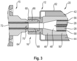
- the 3 shows the connection of the welding torch 14, in particular the torch holder 15 of the same shown in some areas, to the welding wire feed unit 12.
- the torch holder 15 or a connection unit to be coupled thereto has a neck-like coupling section 64 which, with an end section 66 designed with an external thread, fits into the coupling head designed with an internal thread 60 of the welding wire feed unit 12 can be used.
- a central opening is provided in the coupling section 64 , into which a transition sleeve 68 is inserted from an end facing the coupling head 60 .
- the transition sleeve 68 is a section of a wire guide channel 70 of the torch holder 15 or, if present, formed of a connecting unit that couples them.
- This section of the wire guide channel can, for example, taper in the wire feed direction, so that an essentially stepless transition from the wire guide channel 18 of the welding wire feed unit 12 to the section of the wire guide channel 70 of the torch receptacle 15 or the connecting unit formed in a wire core 72 is provided.
- the welding torch coupling area 16 of the welding wire feed unit 12 shown can have a conventional structure, as is also used in systems in which only a single wire guide channel is provided for feeding a single welding wire to a welding torch.
- the feed unit coupling areas 30, 32, with which the two welding wire take-up cables 22, 24 can be coupled to the respective welding wire feed units 34, 36 to be coupled thereto can have a structure such as is conventionally provided with only a single wire guide channel torch cables used.
- an inductively operating welding wire sensor 74 can be provided in the area of the welding wire feed unit 12 . If a welding wire conveyed by one of the two welding wire feed units 34, 36 moves in the wire guide channel 18 of the welding wire feed unit 12, the sensor 74 can detect this or input a corresponding detection signal into the control system 38, so that feedback information is provided therein to indicate that the controlled by this welding wire feed unit promotes a welding wire in the direction of the welding torch 14 in the correct way.
- the welding wire feed system 10 can be designed with a sheathing or jacket, in particular in the area of the two welding wire holding cables 22, 24, in which the two welding wire holding cables 22, 24 or the wire guide channels formed therein.
- This jacket can end just before the feed unit coupling areas 30, 32, so that the two welding wire receiving cables 22, 24 can then run independently of one another to the welding wire feed unit 34, 36 to be coupled with them.
- the welding wire feed unit 12 can also have a flexible, cable-like longitudinal section between the diverter area 20 and the coupling head 60, which can correspond, for example, to the structure of the welding wire receiving cables 22, 24 in terms of its structure. In such a configuration, the switch area 20 is further away from the welding torch coupling area 16 than in the 1 shown configuration.
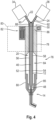
- FIG. 10 Another embodiment of the welding wire feed system 10, which allows it to be easily integrated into an arm 76 of a welding robot, is disclosed in 4 shown.
- This in figure 4 Welding wire feed system 10 shown is designed in such a way that, compared to the basic representation of FIG 1 a significantly larger length section is present, in which the two wire cores 56, 58 or the wire guide channels 26, 28 formed therein are brought together in the welding wire feed unit 12 in order to form a structurally unified, hose-like area which is arranged to run inside the arm 76 can.
- the fifth axis 78 designed as a hollow shaft and the sixth axis 80 of the arm 76 arranged coaxially thereto and also designed as a hollow shaft 4
- the unified length section 84 of the welding wire feed unit 12 runs in the inner volume area of the two axes 78, 80 designed as hollow shafts.
- This length section 84 is essentially provided by the correspondingly longer diverter area 20 with a connection volume 48 on the one hand and the connection volume 48 on the other hand Channels 52, 54 providing switch body 46.
- the switch body 46 is dimensioned to extend along nearly the entire interior volume area of axles 78,80.
- the welding torch 14 is carried on the arm 76 at an end region 85 of the arm 76 formed in the region of the sixth axis 80 .
- the longitudinal section 84 emerges from the arm 76 or the fifth axis 78 of the same and has the receiving area 50 in this area, in which the e.g wire cores 56, 58 running in the welding wire receiving cables 22, 24 are inserted into the channels 52, 54 of the switch body 46 or corresponding wire cores or the like of the welding wire receiving cables 22, 24 connect or are connected to the wire cores 56, 58 running in the switch body 46.
- the switch body 46 can be connected in a mechanically stable manner to a respective jacket 90, 92 of the welding wire receiving cable 22, 24.
- the welding current conductors 42, 44 provided in association with the welding wire receiving cables 22, 24 can also be routed in the area of the connecting piece 88 from the welding wire receiving cables 22, 24 into the longitudinal area 84, i.e. essentially also into the switch area 20.
- the diverter area 20 provides that length area of the welding wire feed unit 12 in which the two or more welding wire receiving cables 22, 24 or the wire guide channels 26, 28 formed therein are brought together and then in a unified body, namely the switch body 46, until they merge into the connecting volume 48 at the other end of the switch area, through which the welding wire to be used for a welding process to be carried out is guided to the welding torch 14.
- this length range is comparatively short, for example shorter than the length range in which the two welding wire receiving cables 22, 24 run as assemblies that are fundamentally separate from one another, but can optionally be combined by being sheathed with a jacket.
- the longitudinal extent of the switch area 20, in which the wire guide channels 26, 28 or the wire cores 56, 58 providing them run in the switch body 46, is significantly greater than the longitudinal extent of the connection from the receiving area 50 or from the connecting piece 88 to the respective welding wire Welding wire take-up cables 22, 24 guiding feed units 34, 36.
- this longitudinal extent of length section 84 essentially providing switch area 20 can be at least twice, preferably at least three times, the longitudinal extent of welding wire take-up cables 22, 24 leading to welding wire feed units 34, 36.
Landscapes
- Engineering & Computer Science (AREA)
- Physics & Mathematics (AREA)
- Mechanical Engineering (AREA)
- Plasma & Fusion (AREA)
- Optics & Photonics (AREA)
- Arc Welding In General (AREA)
Claims (10)
- Unité de soudage, en particulier robot de soudage, comprenant un système d'alimentation en fil de soudage (10), le système d'alimentation en fil de soudage (10) comprenant une unité d'alimentation en fil de soudage (12) à coupler à une torche de soudage (14) avec un conduit de guidage de fil (18) formé dans celle-ci ainsi qu'avec au moins deux câbles de réception de fil de soudage (22, 24), qui se raccordent à l'unité d'alimentation en fil de soudage (12) dans une zone de commutation (20) et doivent être couplés à une unité d'alimentation en fil de soudage respective (34, 36), chacune avec un conduit de guidage de fil respectif (26, 28) formé dans celle-ci,
caractérisé par un bras (76) comprenant au moins un axe (78, 80) conçu comme un arbre creux, une torche de soudage (14) étant prévue dans une zone d'extrémité (85) du bras (76) et l'unité d'alimentation en fil de soudage (12) s'étendant dans le volume intérieur du bras (76) étant couplée aux câbles de réception de fil de soudage (22, 24) dans l'autre zone d'extrémité (86) du bras (76). - Unité de soudage selon la revendication 1, caractérisée en ce que le conduit de guidage de fil est prévu dans au moins un et de préférence chaque câble de réception de fil de soudage (22, 24) dans un noyau de fil (56, 58) configuré avec un enroulement hélicoïdal dans au moins certaines zones.
- Unité de soudage selon la revendication 1 ou 2, caractérisée en ce que l'unité d'alimentation en fil de soudage (12) présente une zone de couplage de torche de soudage (16) pour coupler l'unité d'alimentation en fil de soudage (12) avec une torche de soudage (14), et en ce que chaque câble de réception de fil de soudage (22, 24) présente une zone de couplage d'unité d'alimentation (30, 32) pour coupler les câbles de réception de fil de soudage (22, 24) avec une unité d'alimentation de fil de soudage respective (34, 36).
- Unité de soudage selon la revendication 3, caractérisée en ce qu'en association avec chaque câble de réception de fil de soudage (22, 24), un conducteur de courant de soudage (42, 44) reliant la zone de couplage de l'unité d'alimentation (30, 32) dudit câble de réception avec la zone de couplage de la torche de soudage (16) de manière électriquement conductrice est prévu.
- Unité de soudage selon l'une des revendications précédentes, caractérisée en ce que l'unité d'alimentation en fil de soudage (12) est couplée à une torche de soudage (14), en ce qu'une unité d'alimentation en fil de soudage (34, 36) est couplée à plusieurs câbles de réception de fil de soudage (22, 24) et de préférence à chaque câble de réception de fil de soudage (22, 24), et en ce qu'un dispositif d'actionnement (38) est prévu pour actionner les unités d'alimentation en fil de soudage (34, 36) de telle sorte qu'un fil de soudage devant être alimentée par l'une de ces unités d'alimentation en fil de soudage (34, 36) en direction de la torche de soudage puisse être alimenté par le conduit de guidage de fil (26, 28) du câble de réception de fil de soudage couplé à cette unité d'alimentation en fil de soudage (34, 36) via la zone de commutation (20) et le conduit de guidage de fil (18) de l'unité d'alimentation en fil de soudage (12) vers la torche de soudage (14).
- Unité de soudage selon les revendications 4 et 5, caractérisée en ce qu'une source de courant de soudage (40) pouvant être actionnée par le dispositif d'actionnement (38) est prévue, le dispositif d'actionnement (38) étant configuré pour actionner la source de courant de soudage (40) afin d'amener un courant de soudage via l'unité d'alimentation en fil de soudage (34, 36) actionnée pour amener un fil de soudage.
- Unité de soudage selon la revendication 5 ou 6, caractérisée en ce qu'en association avec l'unité d'alimentation en fil de soudage (12), au moins un capteur de fil de soudage (74) est prévu pour la détection, de préférence inductive, d'un fil de soudage s'étendant dans le conduit de guidage de fil (18) de l'unité d'alimentation en fil de soudage (12), dans laquelle au moins un capteur de fil de soudage (74) est configuré pour entrer un signal de détection de fil de soudage dans le dispositif d'actionnement (38).
- Unité de soudage selon la revendication 2 et l'une des revendications 3-7, caractérisée en ce que la zone de commutation (20) présente un corps de commutation (46) avec une zone de réception (50) ouverte vers les câbles de réception de fil de soudage (22, 24) pour recevoir les noyaux de fil (56, 58) fournissant les conduits de guidage de fil (26, 28) des câbles de réception de fil de soudage (22, 24).
- Unité de soudage selon l'une des revendications précédentes, caractérisée en ce qu'une extension longitudinale de la zone de commutation (20) est au moins deux fois, de préférence au moins trois fois d'au moins un et de préférence de chaque câble de réception de fil de soudage (22, 24).
- Unité de soudage selon l'une des revendications précédentes, caractérisée en ce que des conduits de guidage de fil (26, 28) formés dans les câbles de réception de fil de soudage (22, 24) sont réunis dans la zone de commutation (20) en un volume de raccordement (48) menant au conduit d'alimentation en fil (18) de l'unité d'alimentation en fil de soudage (12).
Applications Claiming Priority (2)
| Application Number | Priority Date | Filing Date | Title |
|---|---|---|---|
| DE102018107404 | 2018-03-28 | ||
| DE102018114754.6A DE102018114754A1 (de) | 2018-03-28 | 2018-06-20 | Schweißdrahtzuführsystem |
Publications (2)
| Publication Number | Publication Date |
|---|---|
| EP3546104A1 EP3546104A1 (fr) | 2019-10-02 |
| EP3546104B1 true EP3546104B1 (fr) | 2023-04-26 |
Family
ID=65904314
Family Applications (1)
| Application Number | Title | Priority Date | Filing Date |
|---|---|---|---|
| EP19164583.7A Active EP3546104B1 (fr) | 2018-03-28 | 2019-03-22 | Système d'alimentation en fil de soudage |
Country Status (1)
| Country | Link |
|---|---|
| EP (1) | EP3546104B1 (fr) |
Families Citing this family (2)
| Publication number | Priority date | Publication date | Assignee | Title |
|---|---|---|---|---|
| CN113145961B (zh) * | 2021-04-19 | 2024-04-02 | 山西奥斯腾科技有限责任公司 | 一种兼具多路送丝的焊接激光振镜头及其焊接方法 |
| CN114799435A (zh) * | 2022-05-09 | 2022-07-29 | 唐山松下产业机器有限公司 | 导电嘴组件及焊枪 |
Citations (2)
| Publication number | Priority date | Publication date | Assignee | Title |
|---|---|---|---|---|
| JPH01170593A (ja) * | 1987-12-25 | 1989-07-05 | Kawasaki Steel Corp | 溶接ワイヤ送給装置 |
| WO2017068752A1 (fr) * | 2015-10-23 | 2017-04-27 | パナソニックIpマネジメント株式会社 | Chalumeau soudeur |
Family Cites Families (4)
| Publication number | Priority date | Publication date | Assignee | Title |
|---|---|---|---|---|
| US3694620A (en) * | 1970-12-10 | 1972-09-26 | William R Gleason | Dual welding wire feed for arc welder |
| JPS56168967A (en) * | 1980-05-30 | 1981-12-25 | Mitsubishi Electric Corp | Wire feeder for welding |
| JP2006102776A (ja) * | 2004-10-05 | 2006-04-20 | Fanuc Ltd | アーク溶接装置及びアーク溶接ロボットシステム |
| US20160059341A1 (en) * | 2014-08-27 | 2016-03-03 | Lincoln Global, Inc. | Multi-consumable torch tip and systems and methods of using the same |
-
2019
- 2019-03-22 EP EP19164583.7A patent/EP3546104B1/fr active Active
Patent Citations (2)
| Publication number | Priority date | Publication date | Assignee | Title |
|---|---|---|---|---|
| JPH01170593A (ja) * | 1987-12-25 | 1989-07-05 | Kawasaki Steel Corp | 溶接ワイヤ送給装置 |
| WO2017068752A1 (fr) * | 2015-10-23 | 2017-04-27 | パナソニックIpマネジメント株式会社 | Chalumeau soudeur |
Also Published As
| Publication number | Publication date |
|---|---|
| EP3546104A1 (fr) | 2019-10-02 |
Similar Documents
| Publication | Publication Date | Title |
|---|---|---|
| EP1153578B1 (fr) | Instrument chirurgical en forme de pince ou de ciseaux | |
| DE69725981T2 (de) | Ablationskatheter | |
| DE102006049370B4 (de) | Hochfrequenz-Schneideinstrument für ein Endoskop | |
| DE2803275A1 (de) | Hochfrequenzchirurgiegeraet | |
| EP3219654B1 (fr) | Dispositif de traitement de cable | |
| CH618115A5 (fr) | ||
| DE69405679T2 (de) | Vorrichtung zur Sicherstellung der Kontinuität der elektrischen Abschirmung von Kabeln | |
| EP3546104B1 (fr) | Système d'alimentation en fil de soudage | |
| DE2418110B2 (de) | Bowdenzug | |
| EP3413405A1 (fr) | Connecteur | |
| DE3834224C2 (de) | Lichtbogen-Schutzgasschweißbrenner zum Schweißen an schwer zugänglichen Stellen | |
| DE1590801A1 (de) | Elektrische Verbindungsklemme | |
| EP0912287B1 (fr) | Chalumeau muni d'une douille de contact et d'un dispositif d'alimentation | |
| DE102018114754A1 (de) | Schweißdrahtzuführsystem | |
| DE1129639B (de) | Schutzgas-Schweissgeraet mit loesbarem Anschluss der Brenner-Leitungen | |
| DE10162455A1 (de) | Staubsaugerteil | |
| WO2004042872A1 (fr) | Vis de contact | |
| DE1750392A1 (de) | Vorrichtung zum Anschluss einer elektrischen Leitung an einen Schlauch | |
| EP3391468B1 (fr) | Coupleur entre un connecteur coaxial et un câble coaxial | |
| EP3696369A1 (fr) | Dispositif de forage du sol pour un forage dirigé par câble, procédé de forage du sol dirigé par câble et utilisation lors du forage du sol dirigé par câble | |
| DE4331304B4 (de) | Medizinisch-chirurgische Sensoranordnung | |
| EP0184746A1 (fr) | Instrument dentaire de percussion | |
| EP4098478B1 (fr) | Logement de câble pour un câble de charge conçu sous la forme de câble en spirale pour une station de charge pour véhicules électriques | |
| DE202017000999U1 (de) | Drahtzuführvorrichtung und Drahtzuführvorrichtungsverbindung | |
| EP0531690B1 (fr) | Raccord de haute tension |
Legal Events
| Date | Code | Title | Description |
|---|---|---|---|
| PUAI | Public reference made under article 153(3) epc to a published international application that has entered the european phase |
Free format text: ORIGINAL CODE: 0009012 |
|
| STAA | Information on the status of an ep patent application or granted ep patent |
Free format text: STATUS: THE APPLICATION HAS BEEN PUBLISHED |
|
| AK | Designated contracting states |
Kind code of ref document: A1 Designated state(s): AL AT BE BG CH CY CZ DE DK EE ES FI FR GB GR HR HU IE IS IT LI LT LU LV MC MK MT NL NO PL PT RO RS SE SI SK SM TR |
|
| AX | Request for extension of the european patent |
Extension state: BA ME |
|
| STAA | Information on the status of an ep patent application or granted ep patent |
Free format text: STATUS: REQUEST FOR EXAMINATION WAS MADE |
|
| 17P | Request for examination filed |
Effective date: 20200401 |
|
| RBV | Designated contracting states (corrected) |
Designated state(s): AL AT BE BG CH CY CZ DE DK EE ES FI FR GB GR HR HU IE IS IT LI LT LU LV MC MK MT NL NO PL PT RO RS SE SI SK SM TR |
|
| RAP1 | Party data changed (applicant data changed or rights of an application transferred) |
Owner name: PUREM GMBH |
|
| GRAP | Despatch of communication of intention to grant a patent |
Free format text: ORIGINAL CODE: EPIDOSNIGR1 |
|
| STAA | Information on the status of an ep patent application or granted ep patent |
Free format text: STATUS: GRANT OF PATENT IS INTENDED |
|
| INTG | Intention to grant announced |
Effective date: 20230113 |
|
| GRAS | Grant fee paid |
Free format text: ORIGINAL CODE: EPIDOSNIGR3 |
|
| GRAA | (expected) grant |
Free format text: ORIGINAL CODE: 0009210 |
|
| STAA | Information on the status of an ep patent application or granted ep patent |
Free format text: STATUS: THE PATENT HAS BEEN GRANTED |
|
| AK | Designated contracting states |
Kind code of ref document: B1 Designated state(s): AL AT BE BG CH CY CZ DE DK EE ES FI FR GB GR HR HU IE IS IT LI LT LU LV MC MK MT NL NO PL PT RO RS SE SI SK SM TR |
|
| REG | Reference to a national code |
Ref country code: GB Ref legal event code: FG4D Free format text: NOT ENGLISH |
|
| REG | Reference to a national code |
Ref country code: CH Ref legal event code: EP |
|
| REG | Reference to a national code |
Ref country code: DE Ref legal event code: R096 Ref document number: 502019007533 Country of ref document: DE |
|
| REG | Reference to a national code |
Ref country code: AT Ref legal event code: REF Ref document number: 1562483 Country of ref document: AT Kind code of ref document: T Effective date: 20230515 |
|
| REG | Reference to a national code |
Ref country code: IE Ref legal event code: FG4D Free format text: LANGUAGE OF EP DOCUMENT: GERMAN |
|
| REG | Reference to a national code |
Ref country code: LT Ref legal event code: MG9D |
|
| REG | Reference to a national code |
Ref country code: NL Ref legal event code: MP Effective date: 20230426 |
|
| PG25 | Lapsed in a contracting state [announced via postgrant information from national office to epo] |
Ref country code: NL Free format text: LAPSE BECAUSE OF FAILURE TO SUBMIT A TRANSLATION OF THE DESCRIPTION OR TO PAY THE FEE WITHIN THE PRESCRIBED TIME-LIMIT Effective date: 20230426 |
|
| PG25 | Lapsed in a contracting state [announced via postgrant information from national office to epo] |
Ref country code: SE Free format text: LAPSE BECAUSE OF FAILURE TO SUBMIT A TRANSLATION OF THE DESCRIPTION OR TO PAY THE FEE WITHIN THE PRESCRIBED TIME-LIMIT Effective date: 20230426 Ref country code: PT Free format text: LAPSE BECAUSE OF FAILURE TO SUBMIT A TRANSLATION OF THE DESCRIPTION OR TO PAY THE FEE WITHIN THE PRESCRIBED TIME-LIMIT Effective date: 20230828 Ref country code: NO Free format text: LAPSE BECAUSE OF FAILURE TO SUBMIT A TRANSLATION OF THE DESCRIPTION OR TO PAY THE FEE WITHIN THE PRESCRIBED TIME-LIMIT Effective date: 20230726 Ref country code: ES Free format text: LAPSE BECAUSE OF FAILURE TO SUBMIT A TRANSLATION OF THE DESCRIPTION OR TO PAY THE FEE WITHIN THE PRESCRIBED TIME-LIMIT Effective date: 20230426 |
|
| PG25 | Lapsed in a contracting state [announced via postgrant information from national office to epo] |
Ref country code: RS Free format text: LAPSE BECAUSE OF FAILURE TO SUBMIT A TRANSLATION OF THE DESCRIPTION OR TO PAY THE FEE WITHIN THE PRESCRIBED TIME-LIMIT Effective date: 20230426 Ref country code: PL Free format text: LAPSE BECAUSE OF FAILURE TO SUBMIT A TRANSLATION OF THE DESCRIPTION OR TO PAY THE FEE WITHIN THE PRESCRIBED TIME-LIMIT Effective date: 20230426 Ref country code: LV Free format text: LAPSE BECAUSE OF FAILURE TO SUBMIT A TRANSLATION OF THE DESCRIPTION OR TO PAY THE FEE WITHIN THE PRESCRIBED TIME-LIMIT Effective date: 20230426 Ref country code: LT Free format text: LAPSE BECAUSE OF FAILURE TO SUBMIT A TRANSLATION OF THE DESCRIPTION OR TO PAY THE FEE WITHIN THE PRESCRIBED TIME-LIMIT Effective date: 20230426 Ref country code: IS Free format text: LAPSE BECAUSE OF FAILURE TO SUBMIT A TRANSLATION OF THE DESCRIPTION OR TO PAY THE FEE WITHIN THE PRESCRIBED TIME-LIMIT Effective date: 20230826 Ref country code: HR Free format text: LAPSE BECAUSE OF FAILURE TO SUBMIT A TRANSLATION OF THE DESCRIPTION OR TO PAY THE FEE WITHIN THE PRESCRIBED TIME-LIMIT Effective date: 20230426 Ref country code: GR Free format text: LAPSE BECAUSE OF FAILURE TO SUBMIT A TRANSLATION OF THE DESCRIPTION OR TO PAY THE FEE WITHIN THE PRESCRIBED TIME-LIMIT Effective date: 20230727 |
|
| PG25 | Lapsed in a contracting state [announced via postgrant information from national office to epo] |
Ref country code: FI Free format text: LAPSE BECAUSE OF FAILURE TO SUBMIT A TRANSLATION OF THE DESCRIPTION OR TO PAY THE FEE WITHIN THE PRESCRIBED TIME-LIMIT Effective date: 20230426 |
|
| PG25 | Lapsed in a contracting state [announced via postgrant information from national office to epo] |
Ref country code: SK Free format text: LAPSE BECAUSE OF FAILURE TO SUBMIT A TRANSLATION OF THE DESCRIPTION OR TO PAY THE FEE WITHIN THE PRESCRIBED TIME-LIMIT Effective date: 20230426 |
|
| REG | Reference to a national code |
Ref country code: DE Ref legal event code: R097 Ref document number: 502019007533 Country of ref document: DE |
|
| PG25 | Lapsed in a contracting state [announced via postgrant information from national office to epo] |
Ref country code: SM Free format text: LAPSE BECAUSE OF FAILURE TO SUBMIT A TRANSLATION OF THE DESCRIPTION OR TO PAY THE FEE WITHIN THE PRESCRIBED TIME-LIMIT Effective date: 20230426 Ref country code: SK Free format text: LAPSE BECAUSE OF FAILURE TO SUBMIT A TRANSLATION OF THE DESCRIPTION OR TO PAY THE FEE WITHIN THE PRESCRIBED TIME-LIMIT Effective date: 20230426 Ref country code: RO Free format text: LAPSE BECAUSE OF FAILURE TO SUBMIT A TRANSLATION OF THE DESCRIPTION OR TO PAY THE FEE WITHIN THE PRESCRIBED TIME-LIMIT Effective date: 20230426 Ref country code: EE Free format text: LAPSE BECAUSE OF FAILURE TO SUBMIT A TRANSLATION OF THE DESCRIPTION OR TO PAY THE FEE WITHIN THE PRESCRIBED TIME-LIMIT Effective date: 20230426 Ref country code: DK Free format text: LAPSE BECAUSE OF FAILURE TO SUBMIT A TRANSLATION OF THE DESCRIPTION OR TO PAY THE FEE WITHIN THE PRESCRIBED TIME-LIMIT Effective date: 20230426 Ref country code: CZ Free format text: LAPSE BECAUSE OF FAILURE TO SUBMIT A TRANSLATION OF THE DESCRIPTION OR TO PAY THE FEE WITHIN THE PRESCRIBED TIME-LIMIT Effective date: 20230426 |
|
| PLBE | No opposition filed within time limit |
Free format text: ORIGINAL CODE: 0009261 |
|
| STAA | Information on the status of an ep patent application or granted ep patent |
Free format text: STATUS: NO OPPOSITION FILED WITHIN TIME LIMIT |
|
| 26N | No opposition filed |
Effective date: 20240129 |
|
| PG25 | Lapsed in a contracting state [announced via postgrant information from national office to epo] |
Ref country code: SI Free format text: LAPSE BECAUSE OF FAILURE TO SUBMIT A TRANSLATION OF THE DESCRIPTION OR TO PAY THE FEE WITHIN THE PRESCRIBED TIME-LIMIT Effective date: 20230426 |
|
| PG25 | Lapsed in a contracting state [announced via postgrant information from national office to epo] |
Ref country code: SI Free format text: LAPSE BECAUSE OF FAILURE TO SUBMIT A TRANSLATION OF THE DESCRIPTION OR TO PAY THE FEE WITHIN THE PRESCRIBED TIME-LIMIT Effective date: 20230426 Ref country code: IT Free format text: LAPSE BECAUSE OF FAILURE TO SUBMIT A TRANSLATION OF THE DESCRIPTION OR TO PAY THE FEE WITHIN THE PRESCRIBED TIME-LIMIT Effective date: 20230426 |
|
| REG | Reference to a national code |
Ref country code: CH Ref legal event code: PL |
|
| PG25 | Lapsed in a contracting state [announced via postgrant information from national office to epo] |
Ref country code: BG Free format text: LAPSE BECAUSE OF FAILURE TO SUBMIT A TRANSLATION OF THE DESCRIPTION OR TO PAY THE FEE WITHIN THE PRESCRIBED TIME-LIMIT Effective date: 20230426 |
|
| PG25 | Lapsed in a contracting state [announced via postgrant information from national office to epo] |
Ref country code: LU Free format text: LAPSE BECAUSE OF NON-PAYMENT OF DUE FEES Effective date: 20240322 |
|
| PG25 | Lapsed in a contracting state [announced via postgrant information from national office to epo] |
Ref country code: MC Free format text: LAPSE BECAUSE OF FAILURE TO SUBMIT A TRANSLATION OF THE DESCRIPTION OR TO PAY THE FEE WITHIN THE PRESCRIBED TIME-LIMIT Effective date: 20230426 |
|
| PG25 | Lapsed in a contracting state [announced via postgrant information from national office to epo] |
Ref country code: MC Free format text: LAPSE BECAUSE OF FAILURE TO SUBMIT A TRANSLATION OF THE DESCRIPTION OR TO PAY THE FEE WITHIN THE PRESCRIBED TIME-LIMIT Effective date: 20230426 Ref country code: LU Free format text: LAPSE BECAUSE OF NON-PAYMENT OF DUE FEES Effective date: 20240322 Ref country code: BG Free format text: LAPSE BECAUSE OF FAILURE TO SUBMIT A TRANSLATION OF THE DESCRIPTION OR TO PAY THE FEE WITHIN THE PRESCRIBED TIME-LIMIT Effective date: 20230426 |
|
| REG | Reference to a national code |
Ref country code: BE Ref legal event code: MM Effective date: 20240331 |
|
| PG25 | Lapsed in a contracting state [announced via postgrant information from national office to epo] |
Ref country code: BE Free format text: LAPSE BECAUSE OF NON-PAYMENT OF DUE FEES Effective date: 20240331 |
|
| PG25 | Lapsed in a contracting state [announced via postgrant information from national office to epo] |
Ref country code: IE Free format text: LAPSE BECAUSE OF NON-PAYMENT OF DUE FEES Effective date: 20240322 |
|
| PG25 | Lapsed in a contracting state [announced via postgrant information from national office to epo] |
Ref country code: IE Free format text: LAPSE BECAUSE OF NON-PAYMENT OF DUE FEES Effective date: 20240322 Ref country code: BE Free format text: LAPSE BECAUSE OF NON-PAYMENT OF DUE FEES Effective date: 20240331 Ref country code: CH Free format text: LAPSE BECAUSE OF NON-PAYMENT OF DUE FEES Effective date: 20240331 |
|
| REG | Reference to a national code |
Ref country code: AT Ref legal event code: MM01 Ref document number: 1562483 Country of ref document: AT Kind code of ref document: T Effective date: 20240322 |
|
| PG25 | Lapsed in a contracting state [announced via postgrant information from national office to epo] |
Ref country code: AT Free format text: LAPSE BECAUSE OF NON-PAYMENT OF DUE FEES Effective date: 20240322 |
|
| PG25 | Lapsed in a contracting state [announced via postgrant information from national office to epo] |
Ref country code: CY Free format text: LAPSE BECAUSE OF FAILURE TO SUBMIT A TRANSLATION OF THE DESCRIPTION OR TO PAY THE FEE WITHIN THE PRESCRIBED TIME-LIMIT; INVALID AB INITIO Effective date: 20190322 |
|
| PG25 | Lapsed in a contracting state [announced via postgrant information from national office to epo] |
Ref country code: HU Free format text: LAPSE BECAUSE OF FAILURE TO SUBMIT A TRANSLATION OF THE DESCRIPTION OR TO PAY THE FEE WITHIN THE PRESCRIBED TIME-LIMIT; INVALID AB INITIO Effective date: 20190322 |
|
| PG25 | Lapsed in a contracting state [announced via postgrant information from national office to epo] |
Ref country code: TR Free format text: LAPSE BECAUSE OF FAILURE TO SUBMIT A TRANSLATION OF THE DESCRIPTION OR TO PAY THE FEE WITHIN THE PRESCRIBED TIME-LIMIT Effective date: 20230426 |
|
| PGFP | Annual fee paid to national office [announced via postgrant information from national office to epo] |
Ref country code: GB Payment date: 20260324 Year of fee payment: 8 |
|
| PGFP | Annual fee paid to national office [announced via postgrant information from national office to epo] |
Ref country code: DE Payment date: 20260320 Year of fee payment: 8 |
|
| PGFP | Annual fee paid to national office [announced via postgrant information from national office to epo] |
Ref country code: FR Payment date: 20260324 Year of fee payment: 8 |