EP3546169A1 - Dispositif de fabrication d'un élément d'étanchéité pour un capuchon - Google Patents
Dispositif de fabrication d'un élément d'étanchéité pour un capuchon Download PDFInfo
- Publication number
- EP3546169A1 EP3546169A1 EP19164942.5A EP19164942A EP3546169A1 EP 3546169 A1 EP3546169 A1 EP 3546169A1 EP 19164942 A EP19164942 A EP 19164942A EP 3546169 A1 EP3546169 A1 EP 3546169A1
- Authority
- EP
- European Patent Office
- Prior art keywords
- punch
- capsule
- forming
- forming ring
- concavity
- Prior art date
- Legal status (The legal status is an assumption and is not a legal conclusion. Google has not performed a legal analysis and makes no representation as to the accuracy of the status listed.)
- Granted
Links
Images

Classifications
-
- B—PERFORMING OPERATIONS; TRANSPORTING
- B29—WORKING OF PLASTICS; WORKING OF SUBSTANCES IN A PLASTIC STATE IN GENERAL
- B29C—SHAPING OR JOINING OF PLASTICS; SHAPING OF MATERIAL IN A PLASTIC STATE, NOT OTHERWISE PROVIDED FOR; AFTER-TREATMENT OF THE SHAPED PRODUCTS, e.g. REPAIRING
- B29C43/00—Compression moulding, i.e. applying external pressure to flow the moulding material; Apparatus therefor
- B29C43/32—Component parts, details or accessories; Auxiliary operations
- B29C43/36—Moulds for making articles of definite length, i.e. discrete articles
- B29C43/361—Moulds for making articles of definite length, i.e. discrete articles with pressing members independently movable of the parts for opening or closing the mould, e.g. movable pistons
-
- B—PERFORMING OPERATIONS; TRANSPORTING
- B21—MECHANICAL METAL-WORKING WITHOUT ESSENTIALLY REMOVING MATERIAL; PUNCHING METAL
- B21D—WORKING OR PROCESSING OF SHEET METAL OR METAL TUBES, RODS OR PROFILES WITHOUT ESSENTIALLY REMOVING MATERIAL; PUNCHING METAL
- B21D51/00—Making hollow objects
- B21D51/16—Making hollow objects characterised by the use of the objects
- B21D51/38—Making inlet or outlet arrangements of cans, tins, baths, bottles, or other vessels; Making can ends; Making closures
- B21D51/44—Making closures, e.g. caps
- B21D51/46—Placing sealings or sealing material
-
- B—PERFORMING OPERATIONS; TRANSPORTING
- B29—WORKING OF PLASTICS; WORKING OF SUBSTANCES IN A PLASTIC STATE IN GENERAL
- B29C—SHAPING OR JOINING OF PLASTICS; SHAPING OF MATERIAL IN A PLASTIC STATE, NOT OTHERWISE PROVIDED FOR; AFTER-TREATMENT OF THE SHAPED PRODUCTS, e.g. REPAIRING
- B29C70/00—Shaping composites, i.e. plastics material comprising reinforcements, fillers or preformed parts, e.g. inserts
- B29C70/68—Shaping composites, i.e. plastics material comprising reinforcements, fillers or preformed parts, e.g. inserts by incorporating or moulding on preformed parts, e.g. inserts or layers, e.g. foam blocks
- B29C70/78—Moulding material on one side only of the preformed part
- B29C70/80—Moulding sealing material into closure members
-
- B—PERFORMING OPERATIONS; TRANSPORTING
- B29—WORKING OF PLASTICS; WORKING OF SUBSTANCES IN A PLASTIC STATE IN GENERAL
- B29C—SHAPING OR JOINING OF PLASTICS; SHAPING OF MATERIAL IN A PLASTIC STATE, NOT OTHERWISE PROVIDED FOR; AFTER-TREATMENT OF THE SHAPED PRODUCTS, e.g. REPAIRING
- B29C43/00—Compression moulding, i.e. applying external pressure to flow the moulding material; Apparatus therefor
- B29C43/32—Component parts, details or accessories; Auxiliary operations
- B29C43/36—Moulds for making articles of definite length, i.e. discrete articles
- B29C43/361—Moulds for making articles of definite length, i.e. discrete articles with pressing members independently movable of the parts for opening or closing the mould, e.g. movable pistons
- B29C2043/3613—Moulds for making articles of definite length, i.e. discrete articles with pressing members independently movable of the parts for opening or closing the mould, e.g. movable pistons applying pressure locally
-
- B—PERFORMING OPERATIONS; TRANSPORTING
- B29—WORKING OF PLASTICS; WORKING OF SUBSTANCES IN A PLASTIC STATE IN GENERAL
- B29C—SHAPING OR JOINING OF PLASTICS; SHAPING OF MATERIAL IN A PLASTIC STATE, NOT OTHERWISE PROVIDED FOR; AFTER-TREATMENT OF THE SHAPED PRODUCTS, e.g. REPAIRING
- B29C43/00—Compression moulding, i.e. applying external pressure to flow the moulding material; Apparatus therefor
- B29C43/32—Component parts, details or accessories; Auxiliary operations
- B29C43/36—Moulds for making articles of definite length, i.e. discrete articles
- B29C43/361—Moulds for making articles of definite length, i.e. discrete articles with pressing members independently movable of the parts for opening or closing the mould, e.g. movable pistons
- B29C2043/3615—Forming elements, e.g. mandrels or rams or stampers or pistons or plungers or punching devices
- B29C2043/3628—Forming elements, e.g. mandrels or rams or stampers or pistons or plungers or punching devices moving inside a barrel or container like sleeve
-
- B—PERFORMING OPERATIONS; TRANSPORTING
- B29—WORKING OF PLASTICS; WORKING OF SUBSTANCES IN A PLASTIC STATE IN GENERAL
- B29C—SHAPING OR JOINING OF PLASTICS; SHAPING OF MATERIAL IN A PLASTIC STATE, NOT OTHERWISE PROVIDED FOR; AFTER-TREATMENT OF THE SHAPED PRODUCTS, e.g. REPAIRING
- B29C43/00—Compression moulding, i.e. applying external pressure to flow the moulding material; Apparatus therefor
- B29C43/32—Component parts, details or accessories; Auxiliary operations
- B29C43/36—Moulds for making articles of definite length, i.e. discrete articles
- B29C43/361—Moulds for making articles of definite length, i.e. discrete articles with pressing members independently movable of the parts for opening or closing the mould, e.g. movable pistons
- B29C2043/3615—Forming elements, e.g. mandrels or rams or stampers or pistons or plungers or punching devices
- B29C2043/3634—Forming elements, e.g. mandrels or rams or stampers or pistons or plungers or punching devices having specific surface shape, e.g. grooves, projections, corrugations
-
- B—PERFORMING OPERATIONS; TRANSPORTING
- B29—WORKING OF PLASTICS; WORKING OF SUBSTANCES IN A PLASTIC STATE IN GENERAL
- B29C—SHAPING OR JOINING OF PLASTICS; SHAPING OF MATERIAL IN A PLASTIC STATE, NOT OTHERWISE PROVIDED FOR; AFTER-TREATMENT OF THE SHAPED PRODUCTS, e.g. REPAIRING
- B29C43/00—Compression moulding, i.e. applying external pressure to flow the moulding material; Apparatus therefor
- B29C43/02—Compression moulding, i.e. applying external pressure to flow the moulding material; Apparatus therefor of articles of definite length, i.e. discrete articles
- B29C43/18—Compression moulding, i.e. applying external pressure to flow the moulding material; Apparatus therefor of articles of definite length, i.e. discrete articles incorporating preformed parts or layers, e.g. compression moulding around inserts or for coating articles
-
- B—PERFORMING OPERATIONS; TRANSPORTING
- B29—WORKING OF PLASTICS; WORKING OF SUBSTANCES IN A PLASTIC STATE IN GENERAL
- B29K—INDEXING SCHEME ASSOCIATED WITH SUBCLASSES B29B, B29C OR B29D, RELATING TO MOULDING MATERIALS OR TO MATERIALS FOR MOULDS, REINFORCEMENTS, FILLERS OR PREFORMED PARTS, e.g. INSERTS
- B29K2705/00—Use of metals, their alloys or their compounds, for preformed parts, e.g. for inserts
-
- B—PERFORMING OPERATIONS; TRANSPORTING
- B29—WORKING OF PLASTICS; WORKING OF SUBSTANCES IN A PLASTIC STATE IN GENERAL
- B29K—INDEXING SCHEME ASSOCIATED WITH SUBCLASSES B29B, B29C OR B29D, RELATING TO MOULDING MATERIALS OR TO MATERIALS FOR MOULDS, REINFORCEMENTS, FILLERS OR PREFORMED PARTS, e.g. INSERTS
- B29K2705/00—Use of metals, their alloys or their compounds, for preformed parts, e.g. for inserts
- B29K2705/06—Tin
-
- B—PERFORMING OPERATIONS; TRANSPORTING
- B29—WORKING OF PLASTICS; WORKING OF SUBSTANCES IN A PLASTIC STATE IN GENERAL
- B29L—INDEXING SCHEME ASSOCIATED WITH SUBCLASS B29C, RELATING TO PARTICULAR ARTICLES
- B29L2031/00—Other particular articles
- B29L2031/56—Stoppers or lids for bottles, jars, or the like, e.g. closures
Definitions
- the present invention relates to an internal sealing element for a cap, for example a crown cap, designed to be applied for closing a bottle.
- this invention relates to a forming device used for moulding the element directly inside the cap.
- caps for example so-called crown caps, or screw caps, or other caps of different types, have been used for closing bottles, in particular glass bottles.
- crown cap For simplicity and clarity of description, reference will be made below only to the crown cap, but it will be understood that the device described and claimed in this invention may also be applied in all those cases in which, irrespective of the type of a cap used, the inside of the latter comprises a sealing element of the type described below.
- the crown cap is formed by a metal capsule which through a manual or pneumatic capping machine is gripped to the neck of the bottle.
- a sealing element designed to make a fluid tight seal of the cap on the neck of the bottle is usually located inside the capsule.
- the sealing element currently consists of a disc, approximately of the diameter of the bottom of the concavity of the capsule, or just less, made of plastic material and adhering to the inner surface of the capsule.
- the sealing element simulates the presence of the so-called “ bidule ", the cup-shaped sealing element provided to collect sediments during the re-fermentation and fining step of the wine, for production according to the known Champenoise method.
- the making of the sealing element inside the capsule comprises positioning (inserting) on the bottom of the cavity formed by it a charge of plastic material (heated beforehand) and pressing the charge with a mould.
- the action of pressing the mould determines the expansion of the charge of heated plastic material adhering to the inner wall of the capsule and thus filling the empty spaces left by the mould, thereby forming the sealing element.
- the aim of the invention is to provide means for making the internal element of the cap, in particular consisting of a device for making the element.
- Another aim of the invention is to provide a device for making the internal element which is able to form the internal element easily and without causing the detachment of the disc from the bottom of the capsule.
- Another aim of the invention is to provide a device which allows the sealing element inside the cap to be made on a large-scale, in a relatively simple, efficient and inexpensive manner.
- the reference numeral 1 denotes a cap, for example but without limiting the scope of the crown type, for closing bottles for example of sparkling wines.
- cap of the crown type As mentioned in the introduction, for simplicity of description reference will be made to a cap of the crown type, but it must be understood that the forming device according to the invention may also be applied for caps of a different type, for example with a screw.
- the cap 1 comprises a capsule 2 (made of metal) designed to be gripped to the neck 3 of a bottle ( figure 4 ) in known manner, by means of a manual capping machine or pneumatic capping machine (both not illustrated).
- the cap 1 also comprises a sealing element 4, which is situated inside the concavity 5 of the capsule 2 and is cup-shaped.
- the sealing element 4 might perform the function of the so-called 'bidule' in the context of the classic method of production of sparkling wines.
- the sealing element 4 comprises a base 6, which is almost disc-shaped, adhering to and integral with the bottom 7 of the concavity 5 of the capsule 2, and by a collar 8, slightly flared, defined by a single annular flange 9 which extends from the base 6 for engaging in a sealed fashion with the inner part of the neck 3 of the bottle.
- the base 6 is substantially circular and has a diameter that approximates the diameter of the bottom 7 of the concavity 5 of the capsule 2.
- the outer surface of the flange 9, which has a substantially circular extension, is at a distance D from the outer surface of the base 6.
- the distance D is between 15% and 50%, more preferably between 20% and 40%, even more preferably between 25% and 30%, of the diameter of the base 6.
- a layer of paint is interposed between the bottom 7 and the sealing element 4.
- the layer of paint is in the form of adhesive paint.
- the sealing element 4 is shaped and constrained on the capsule 2 by inserting and moulding a plastic material directly inside the concavity 5 of the capsule 2, that is to say, on the bottom 7 of the concavity 5 of the capsule 2, after the bottom 7 has been coated with the above-mentioned layer of paint.
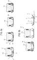
- the process is illustrated in Figures 3a and 3b .
- the production of the cap 1 comprises the steps of coating the bottom 7 of the concavity 5 of the capsule 2 with a layer of paint, and subsequently, as illustrated in Figures 3a and 3b , positioning (inserting) on the bottom 7 a charge 13 of plastic material (heated beforehand), pressing the charge 13 with a mould 14 for imparting to the charge 13 a preliminary shape to the sealing element 4 ( figures 2a and 2b ).
- the mould used is identified on a forming device 14 for making the sealing element 4 comprising an axially movable punch 14a, and a forming ring 14b fitted outside on the punch 14a and slidable axially relative to it.
- the support and movement part of the punch 14a is not illustrated in the accompanying drawings, as it can be easily inferred by an expert in the field.
- the movement of the punch will be determined by a suitable press (also not illustrated) and by actuating the moulding step of the sealing element 4 the capsule 2 will be located at the forming device, beneath the punch 14a and the forming ring 14b, already provided with the charge 13 of plastic material.
- Both the punch 14a and the forming ring 14b are contained in a slidable fashion inside a tubular containment liner 17, designed to guide the axial movements of these two components and designed to introduce, with an overall axial movement, for example downwards, in the concavity 5 of the capsule 2.
- the free head 14c of the forming ring 14b has an enlargement 18 having an extension towards the inside of the ring, which is designed to impart a curved shape towards the outside of the wall of the collar 8, as will become more evident from the following description, creating in this way the lip 11.
- the enlargement 18 has a lobe-shaped cross-section and its thickness in a radial direction is such as to determine a predetermined distance D of the collar 8 from the outer periphery of the base 6.
- the thickness of the enlargement 18 is such as to determine a distance D which is between 15% and 50% of the diameter of the base 6.
- the free end 14d of the punch 14a has a narrowing of the section, in an axial direction, such that it corresponds to the extension towards the inside of the enlargement 17 of the forming ring 14b, when the end of the punch 14d is flush with the free head 14c of the forming ring.
- the forming ring 14b is preloaded elastically in such a way as to remain offset towards the outside with the relative free head 14c with respect to the free end 14d of the punch 14a, under non-operating conditions, in particular when the punch 14a is far from the bottom 7 of the concavity 5.
- the elastic pre-loading of the ring forming is obtained by means of one or more springs 21 arranged between corresponding opposing shoulders 19, 20 of the punch 14a and of the forming ring 14b ( Figures 2a, 2b and 3a, 3b ).
- the spring or springs 21 are located around the punch 14a and are contained inside corresponding walls 22 which extend from the forming ring 14b, in such a way that they remain interposed between the latter and the punch.
- the shoulder of the forming ring 20 is formed towards the inside of it, in a radial direction, whilst the shoulder of the punch 19 extends outwards.
- the spring, or the springs 21, are inserted between the two shoulders, under the shoulder of the punch 19 and above the shoulder of the forming ring.
- the spring or the springs 21 are positioned around the corresponding walls 22 of the forming ring 14b surrounding the punch 14a, and are contained in the liner 17 interposed between the latter and the walls 22, again below the shoulder of the punch 19.
- the second configuration requires the provision of an annular cavity 24, that is to say, a seat, around the punch 14a which allows the wall 22 to slide upwards beyond the shoulder of the punch, inserting inside the cavity.
- a series of spacer sectors 15 are applied on the free head 14c of the forming ring 14b so as to leave a predetermined distance, corresponding to their thickness, between the free head of the forming ring 14b and the bottom 7 of the concavity 5 when the punch 14a and the forming ring 14b are in the compression position of the charge 13 (second image of Figure 2b ), as described in more detail below.
- the punch 14a In the operating position, the punch 14a is raised and the forming ring 14b is moved axially under the thrust of the elastic reaction of the springs 21, in such a way that the relative free end face 14c is offset outwards with respect to the free end 14d of the punch 14a.
- a layer of adhesive paint designed to remain interposed between the bottom 7 and the sealing element 4 being formed, in order to keep the latter joined to the capsule 2.
- a charge of plastic material 13 is placed on the bottom 7 when the capsule is below the forming device 14, or immediately before.
- the punch 14a - forming ring 14b - liner 17 assembly is actuated, causing the progressive lowering and the introduction in the concavity 5 of the capsule 2.
- the lower part of the liner 17 is very close to the walls of the capsule 2 and stops when in contact with the bottom 7 of the concavity 5, adhering on the circumference as external as possible.
- the forming ring 14b also moves downwards, along with the movement, again downwards, of the punch 14a, until the spacer sectors 15 applied on the free head 14e of the forming ring 14b come into contact with the base 7.
- the plastic material under the pushing action of the punch 14a, expands in the forming chamber 16 delimited by the bottom 7 of the concavity 5, by the lobe-shaped enlargement 17 of the forming ring 14b, and by the free end 14d of the punch, with a narrow section, thereby forming the sealing element 4.
- the plastic material is introduced into the free space left between the free head 14c of the forming ring 14b and the bottom 7 thanks to the presence of the spacer sectors 15 until reaching the wall of the capsule 2, and between the enlargement in the form of a lobe 17 and the punch 14a, forming the lip 11 of the sealing element 4.
- the punch 14a reverses the direction of its movement and rises.
- the springs 21 react elastically pushing the forming ring 14b downwards and keeping pressed against the bottom 7 until the head 14d of the punch is moved above the lobe-shaped enlargement 17. At that point, the springs 21 are completely extended and the forming ring 14b also rises.
- the fluidity which still characterises the plastic material determines the closing of the grooves left on the bottom of the sealing element 4 by the spacer sectors 15, re-establishing the capacity for the cap to create the seal on the neck of the bottle.
- This splitting of the movement of the punch - forming ring assembly allows the extraction, which would otherwise be impossible, of the lip 11 from the space between lobe-shaped enlargement 17 and the punch 14a.
- the forming device 14 releases the sealing element 4 firstly in a central region of the sealing element 4, inside the flange 9 and corresponding to the punch 14a, and then in an annular region, outside the flange 9, corresponding to the lobe-shaped enlargement 17 of the forming ring 14b.
- the shape and the operating sequence which characterise the forming device 14 described here allow the preset aims in the introduction to be achieved, that is to say, to provide means for making the sealing element inside the cap which operates easily and without causing the detachment of the disc from the bottom of the capsule and which allows the making of the sealing element inside the cap on a large-scale in a relatively simple, efficient and inexpensive manner.
Landscapes
- Engineering & Computer Science (AREA)
- Mechanical Engineering (AREA)
- Chemical & Material Sciences (AREA)
- Composite Materials (AREA)
- Closures For Containers (AREA)
- Cable Accessories (AREA)
- Connector Housings Or Holding Contact Members (AREA)
- Pressure Vessels And Lids Thereof (AREA)
Applications Claiming Priority (1)
| Application Number | Priority Date | Filing Date | Title |
|---|---|---|---|
| IT102018000004055A IT201800004055A1 (it) | 2018-03-28 | 2018-03-28 | Dispositivo formatore per la realizzazione di un rivestimento di tenuta interno per un tappo. |
Publications (2)
| Publication Number | Publication Date |
|---|---|
| EP3546169A1 true EP3546169A1 (fr) | 2019-10-02 |
| EP3546169B1 EP3546169B1 (fr) | 2021-08-11 |
Family
ID=62597966
Family Applications (1)
| Application Number | Title | Priority Date | Filing Date |
|---|---|---|---|
| EP19164942.5A Active EP3546169B1 (fr) | 2018-03-28 | 2019-03-25 | Dispositif de fabrication d'un élément d'étanchéité pour un capuchon |
Country Status (4)
| Country | Link |
|---|---|
| EP (1) | EP3546169B1 (fr) |
| ES (1) | ES2896902T3 (fr) |
| IT (1) | IT201800004055A1 (fr) |
| PT (1) | PT3546169T (fr) |
Citations (6)
| Publication number | Priority date | Publication date | Assignee | Title |
|---|---|---|---|---|
| US3038624A (en) * | 1955-09-22 | 1962-06-12 | Huber Karl | Container closure |
| US3278985A (en) * | 1965-06-25 | 1966-10-18 | Gros Ite Industries | Molding devices |
| US4094460A (en) * | 1976-04-26 | 1978-06-13 | Aluminum Company Of America | Closure assembly and package |
| US4398875A (en) * | 1980-04-28 | 1983-08-16 | Toyo Seikan Kaisha, Ltd. | Molding tool for forming a closure shell liner |
| JPS62135165A (ja) * | 1985-12-04 | 1987-06-18 | 喜多産業株式会社 | ライナ−付き容器蓋及びその製造方法 |
| EP1814705A2 (fr) * | 2004-10-13 | 2007-08-08 | Sacmi Cooperativa Meccanici Imola Societa' Cooperativa | Capuchon de fermeture de contenants et dispositif de fabrication de doublure |
-
2018
- 2018-03-28 IT IT102018000004055A patent/IT201800004055A1/it unknown
-
2019
- 2019-03-25 PT PT191649425T patent/PT3546169T/pt unknown
- 2019-03-25 EP EP19164942.5A patent/EP3546169B1/fr active Active
- 2019-03-25 ES ES19164942T patent/ES2896902T3/es active Active
Patent Citations (6)
| Publication number | Priority date | Publication date | Assignee | Title |
|---|---|---|---|---|
| US3038624A (en) * | 1955-09-22 | 1962-06-12 | Huber Karl | Container closure |
| US3278985A (en) * | 1965-06-25 | 1966-10-18 | Gros Ite Industries | Molding devices |
| US4094460A (en) * | 1976-04-26 | 1978-06-13 | Aluminum Company Of America | Closure assembly and package |
| US4398875A (en) * | 1980-04-28 | 1983-08-16 | Toyo Seikan Kaisha, Ltd. | Molding tool for forming a closure shell liner |
| JPS62135165A (ja) * | 1985-12-04 | 1987-06-18 | 喜多産業株式会社 | ライナ−付き容器蓋及びその製造方法 |
| EP1814705A2 (fr) * | 2004-10-13 | 2007-08-08 | Sacmi Cooperativa Meccanici Imola Societa' Cooperativa | Capuchon de fermeture de contenants et dispositif de fabrication de doublure |
Also Published As
| Publication number | Publication date |
|---|---|
| PT3546169T (pt) | 2021-11-03 |
| EP3546169B1 (fr) | 2021-08-11 |
| ES2896902T3 (es) | 2022-02-28 |
| IT201800004055A1 (it) | 2019-09-28 |
Similar Documents
| Publication | Publication Date | Title |
|---|---|---|
| US10214323B2 (en) | Cap assembly having inside seal | |
| EP2883682B1 (fr) | Buse de soufflage | |
| KR20090076185A (ko) | 금속제 캔의 밀봉립 가공장치 | |
| HU177622B (en) | Process for producing packing ring containing an elastomer ring and a packing piece formed from a polytetrafluoroethylene filler ring | |
| RU2323089C2 (ru) | Способ изготовления бутылки с напрессовываемой крышкой | |
| CN112551461B (zh) | 封盖头、系统和方法 | |
| JPS61111158A (ja) | 遠心分離管のためのひだ寄せ可能なキヤツプ集成体 | |
| US6457341B1 (en) | Forging die | |
| KR20180096692A (ko) | 용기를 위한 폐쇄부 및 금속 폐쇄부를 형성하는 방법 | |
| CN101274482A (zh) | 处理容器的装置、方法及其密封装置 | |
| US3004297A (en) | Method for forming a gasket | |
| EP3546169B1 (fr) | Dispositif de fabrication d'un élément d'étanchéité pour un capuchon | |
| US3207350A (en) | Sealing closure for a crown-type bottle | |
| US2777411A (en) | Method of making lined bottle caps | |
| EP3450344B1 (fr) | Capuchon et son procédé de production | |
| JP5577410B2 (ja) | 金属製缶の密封リップ加工装置 | |
| CN104609023A (zh) | 一种用于安装装饰件的组合瓶盖及其制造方法 | |
| US3936257A (en) | Closed stroke molding | |
| US2098906A (en) | Method of making closure caps | |
| US11702250B2 (en) | Metal closure for a container, method for making the same and method for capping a container with the same | |
| US1927212A (en) | Arched cap bottle seal | |
| CN118768485A (zh) | 模具及模制设备 | |
| WO1997003790A1 (fr) | Procede et appareil d'application d'un obturateur en deux parties sur un flacon | |
| CN116329469B (zh) | 一种双组分环形坯件的终成型装置及方法 | |
| US2327262A (en) | Bottle capper |
Legal Events
| Date | Code | Title | Description |
|---|---|---|---|
| PUAI | Public reference made under article 153(3) epc to a published international application that has entered the european phase |
Free format text: ORIGINAL CODE: 0009012 |
|
| STAA | Information on the status of an ep patent application or granted ep patent |
Free format text: STATUS: THE APPLICATION HAS BEEN PUBLISHED |
|
| AK | Designated contracting states |
Kind code of ref document: A1 Designated state(s): AL AT BE BG CH CY CZ DE DK EE ES FI FR GB GR HR HU IE IS IT LI LT LU LV MC MK MT NL NO PL PT RO RS SE SI SK SM TR |
|
| AX | Request for extension of the european patent |
Extension state: BA ME |
|
| STAA | Information on the status of an ep patent application or granted ep patent |
Free format text: STATUS: REQUEST FOR EXAMINATION WAS MADE |
|
| 17P | Request for examination filed |
Effective date: 20200401 |
|
| RBV | Designated contracting states (corrected) |
Designated state(s): AL AT BE BG CH CY CZ DE DK EE ES FI FR GB GR HR HU IE IS IT LI LT LU LV MC MK MT NL NO PL PT RO RS SE SI SK SM TR |
|
| STAA | Information on the status of an ep patent application or granted ep patent |
Free format text: STATUS: EXAMINATION IS IN PROGRESS |
|
| 17Q | First examination report despatched |
Effective date: 20200813 |
|
| GRAP | Despatch of communication of intention to grant a patent |
Free format text: ORIGINAL CODE: EPIDOSNIGR1 |
|
| STAA | Information on the status of an ep patent application or granted ep patent |
Free format text: STATUS: GRANT OF PATENT IS INTENDED |
|
| RIC1 | Information provided on ipc code assigned before grant |
Ipc: B29K 705/06 20060101ALN20210218BHEP Ipc: B29C 43/36 20060101AFI20210218BHEP Ipc: B29C 70/80 20060101ALI20210218BHEP Ipc: B21D 51/46 20060101ALI20210218BHEP Ipc: B29K 705/00 20060101ALN20210218BHEP Ipc: B29C 43/18 20060101ALN20210218BHEP Ipc: B29L 31/56 20060101ALN20210218BHEP |
|
| INTG | Intention to grant announced |
Effective date: 20210312 |
|
| RIN1 | Information on inventor provided before grant (corrected) |
Inventor name: NALDI, DORIANO Inventor name: WHITE, STEVEN |
|
| GRAS | Grant fee paid |
Free format text: ORIGINAL CODE: EPIDOSNIGR3 |
|
| GRAA | (expected) grant |
Free format text: ORIGINAL CODE: 0009210 |
|
| STAA | Information on the status of an ep patent application or granted ep patent |
Free format text: STATUS: THE PATENT HAS BEEN GRANTED |
|
| AK | Designated contracting states |
Kind code of ref document: B1 Designated state(s): AL AT BE BG CH CY CZ DE DK EE ES FI FR GB GR HR HU IE IS IT LI LT LU LV MC MK MT NL NO PL PT RO RS SE SI SK SM TR |
|
| REG | Reference to a national code |
Ref country code: CH Ref legal event code: EP |
|
| REG | Reference to a national code |
Ref country code: DE Ref legal event code: R096 Ref document number: 602019006706 Country of ref document: DE |
|
| REG | Reference to a national code |
Ref country code: IE Ref legal event code: FG4D Ref country code: AT Ref legal event code: REF Ref document number: 1418918 Country of ref document: AT Kind code of ref document: T Effective date: 20210915 |
|
| REG | Reference to a national code |
Ref country code: PT Ref legal event code: SC4A Ref document number: 3546169 Country of ref document: PT Date of ref document: 20211103 Kind code of ref document: T Free format text: AVAILABILITY OF NATIONAL TRANSLATION Effective date: 20211026 |
|
| REG | Reference to a national code |
Ref country code: LT Ref legal event code: MG9D |
|
| REG | Reference to a national code |
Ref country code: NL Ref legal event code: MP Effective date: 20210811 |
|
| REG | Reference to a national code |
Ref country code: AT Ref legal event code: MK05 Ref document number: 1418918 Country of ref document: AT Kind code of ref document: T Effective date: 20210811 |
|
| PG25 | Lapsed in a contracting state [announced via postgrant information from national office to epo] |
Ref country code: RS Free format text: LAPSE BECAUSE OF FAILURE TO SUBMIT A TRANSLATION OF THE DESCRIPTION OR TO PAY THE FEE WITHIN THE PRESCRIBED TIME-LIMIT Effective date: 20210811 Ref country code: SE Free format text: LAPSE BECAUSE OF FAILURE TO SUBMIT A TRANSLATION OF THE DESCRIPTION OR TO PAY THE FEE WITHIN THE PRESCRIBED TIME-LIMIT Effective date: 20210811 Ref country code: FI Free format text: LAPSE BECAUSE OF FAILURE TO SUBMIT A TRANSLATION OF THE DESCRIPTION OR TO PAY THE FEE WITHIN THE PRESCRIBED TIME-LIMIT Effective date: 20210811 Ref country code: NO Free format text: LAPSE BECAUSE OF FAILURE TO SUBMIT A TRANSLATION OF THE DESCRIPTION OR TO PAY THE FEE WITHIN THE PRESCRIBED TIME-LIMIT Effective date: 20211111 Ref country code: HR Free format text: LAPSE BECAUSE OF FAILURE TO SUBMIT A TRANSLATION OF THE DESCRIPTION OR TO PAY THE FEE WITHIN THE PRESCRIBED TIME-LIMIT Effective date: 20210811 Ref country code: BG Free format text: LAPSE BECAUSE OF FAILURE TO SUBMIT A TRANSLATION OF THE DESCRIPTION OR TO PAY THE FEE WITHIN THE PRESCRIBED TIME-LIMIT Effective date: 20211111 Ref country code: AT Free format text: LAPSE BECAUSE OF FAILURE TO SUBMIT A TRANSLATION OF THE DESCRIPTION OR TO PAY THE FEE WITHIN THE PRESCRIBED TIME-LIMIT Effective date: 20210811 Ref country code: LT Free format text: LAPSE BECAUSE OF FAILURE TO SUBMIT A TRANSLATION OF THE DESCRIPTION OR TO PAY THE FEE WITHIN THE PRESCRIBED TIME-LIMIT Effective date: 20210811 |
|
| PG25 | Lapsed in a contracting state [announced via postgrant information from national office to epo] |
Ref country code: PL Free format text: LAPSE BECAUSE OF FAILURE TO SUBMIT A TRANSLATION OF THE DESCRIPTION OR TO PAY THE FEE WITHIN THE PRESCRIBED TIME-LIMIT Effective date: 20210811 Ref country code: LV Free format text: LAPSE BECAUSE OF FAILURE TO SUBMIT A TRANSLATION OF THE DESCRIPTION OR TO PAY THE FEE WITHIN THE PRESCRIBED TIME-LIMIT Effective date: 20210811 Ref country code: GR Free format text: LAPSE BECAUSE OF FAILURE TO SUBMIT A TRANSLATION OF THE DESCRIPTION OR TO PAY THE FEE WITHIN THE PRESCRIBED TIME-LIMIT Effective date: 20211112 |
|
| REG | Reference to a national code |
Ref country code: ES Ref legal event code: FG2A Ref document number: 2896902 Country of ref document: ES Kind code of ref document: T3 Effective date: 20220228 |
|
| PG25 | Lapsed in a contracting state [announced via postgrant information from national office to epo] |
Ref country code: NL Free format text: LAPSE BECAUSE OF FAILURE TO SUBMIT A TRANSLATION OF THE DESCRIPTION OR TO PAY THE FEE WITHIN THE PRESCRIBED TIME-LIMIT Effective date: 20210811 |
|
| PG25 | Lapsed in a contracting state [announced via postgrant information from national office to epo] |
Ref country code: DK Free format text: LAPSE BECAUSE OF FAILURE TO SUBMIT A TRANSLATION OF THE DESCRIPTION OR TO PAY THE FEE WITHIN THE PRESCRIBED TIME-LIMIT Effective date: 20210811 |
|
| REG | Reference to a national code |
Ref country code: DE Ref legal event code: R097 Ref document number: 602019006706 Country of ref document: DE |
|
| PG25 | Lapsed in a contracting state [announced via postgrant information from national office to epo] |
Ref country code: SM Free format text: LAPSE BECAUSE OF FAILURE TO SUBMIT A TRANSLATION OF THE DESCRIPTION OR TO PAY THE FEE WITHIN THE PRESCRIBED TIME-LIMIT Effective date: 20210811 Ref country code: SK Free format text: LAPSE BECAUSE OF FAILURE TO SUBMIT A TRANSLATION OF THE DESCRIPTION OR TO PAY THE FEE WITHIN THE PRESCRIBED TIME-LIMIT Effective date: 20210811 Ref country code: RO Free format text: LAPSE BECAUSE OF FAILURE TO SUBMIT A TRANSLATION OF THE DESCRIPTION OR TO PAY THE FEE WITHIN THE PRESCRIBED TIME-LIMIT Effective date: 20210811 Ref country code: EE Free format text: LAPSE BECAUSE OF FAILURE TO SUBMIT A TRANSLATION OF THE DESCRIPTION OR TO PAY THE FEE WITHIN THE PRESCRIBED TIME-LIMIT Effective date: 20210811 Ref country code: CZ Free format text: LAPSE BECAUSE OF FAILURE TO SUBMIT A TRANSLATION OF THE DESCRIPTION OR TO PAY THE FEE WITHIN THE PRESCRIBED TIME-LIMIT Effective date: 20210811 Ref country code: AL Free format text: LAPSE BECAUSE OF FAILURE TO SUBMIT A TRANSLATION OF THE DESCRIPTION OR TO PAY THE FEE WITHIN THE PRESCRIBED TIME-LIMIT Effective date: 20210811 |
|
| PLBE | No opposition filed within time limit |
Free format text: ORIGINAL CODE: 0009261 |
|
| STAA | Information on the status of an ep patent application or granted ep patent |
Free format text: STATUS: NO OPPOSITION FILED WITHIN TIME LIMIT |
|
| 26N | No opposition filed |
Effective date: 20220512 |
|
| PG25 | Lapsed in a contracting state [announced via postgrant information from national office to epo] |
Ref country code: SI Free format text: LAPSE BECAUSE OF FAILURE TO SUBMIT A TRANSLATION OF THE DESCRIPTION OR TO PAY THE FEE WITHIN THE PRESCRIBED TIME-LIMIT Effective date: 20210811 |
|
| PG25 | Lapsed in a contracting state [announced via postgrant information from national office to epo] |
Ref country code: MC Free format text: LAPSE BECAUSE OF FAILURE TO SUBMIT A TRANSLATION OF THE DESCRIPTION OR TO PAY THE FEE WITHIN THE PRESCRIBED TIME-LIMIT Effective date: 20210811 |
|
| REG | Reference to a national code |
Ref country code: CH Ref legal event code: PL |
|
| REG | Reference to a national code |
Ref country code: BE Ref legal event code: MM Effective date: 20220331 |
|
| PG25 | Lapsed in a contracting state [announced via postgrant information from national office to epo] |
Ref country code: LU Free format text: LAPSE BECAUSE OF NON-PAYMENT OF DUE FEES Effective date: 20220325 Ref country code: LI Free format text: LAPSE BECAUSE OF NON-PAYMENT OF DUE FEES Effective date: 20220331 Ref country code: IE Free format text: LAPSE BECAUSE OF NON-PAYMENT OF DUE FEES Effective date: 20220325 Ref country code: CH Free format text: LAPSE BECAUSE OF NON-PAYMENT OF DUE FEES Effective date: 20220331 |
|
| PG25 | Lapsed in a contracting state [announced via postgrant information from national office to epo] |
Ref country code: BE Free format text: LAPSE BECAUSE OF NON-PAYMENT OF DUE FEES Effective date: 20220331 |
|
| GBPC | Gb: european patent ceased through non-payment of renewal fee |
Effective date: 20230325 |
|
| PG25 | Lapsed in a contracting state [announced via postgrant information from national office to epo] |
Ref country code: GB Free format text: LAPSE BECAUSE OF NON-PAYMENT OF DUE FEES Effective date: 20230325 |
|
| PG25 | Lapsed in a contracting state [announced via postgrant information from national office to epo] |
Ref country code: GB Free format text: LAPSE BECAUSE OF NON-PAYMENT OF DUE FEES Effective date: 20230325 |
|
| PG25 | Lapsed in a contracting state [announced via postgrant information from national office to epo] |
Ref country code: MK Free format text: LAPSE BECAUSE OF FAILURE TO SUBMIT A TRANSLATION OF THE DESCRIPTION OR TO PAY THE FEE WITHIN THE PRESCRIBED TIME-LIMIT Effective date: 20210811 Ref country code: CY Free format text: LAPSE BECAUSE OF FAILURE TO SUBMIT A TRANSLATION OF THE DESCRIPTION OR TO PAY THE FEE WITHIN THE PRESCRIBED TIME-LIMIT Effective date: 20210811 |
|
| PG25 | Lapsed in a contracting state [announced via postgrant information from national office to epo] |
Ref country code: HU Free format text: LAPSE BECAUSE OF FAILURE TO SUBMIT A TRANSLATION OF THE DESCRIPTION OR TO PAY THE FEE WITHIN THE PRESCRIBED TIME-LIMIT; INVALID AB INITIO Effective date: 20190325 |
|
| PG25 | Lapsed in a contracting state [announced via postgrant information from national office to epo] |
Ref country code: MT Free format text: LAPSE BECAUSE OF FAILURE TO SUBMIT A TRANSLATION OF THE DESCRIPTION OR TO PAY THE FEE WITHIN THE PRESCRIBED TIME-LIMIT Effective date: 20210811 |
|
| PGFP | Annual fee paid to national office [announced via postgrant information from national office to epo] |
Ref country code: DE Payment date: 20250327 Year of fee payment: 7 Ref country code: PT Payment date: 20250305 Year of fee payment: 7 |
|
| PGFP | Annual fee paid to national office [announced via postgrant information from national office to epo] |
Ref country code: FR Payment date: 20250324 Year of fee payment: 7 |
|
| PGFP | Annual fee paid to national office [announced via postgrant information from national office to epo] |
Ref country code: ES Payment date: 20250417 Year of fee payment: 7 |
|
| PGFP | Annual fee paid to national office [announced via postgrant information from national office to epo] |
Ref country code: IT Payment date: 20250327 Year of fee payment: 7 |
|
| PG25 | Lapsed in a contracting state [announced via postgrant information from national office to epo] |
Ref country code: TR Free format text: LAPSE BECAUSE OF FAILURE TO SUBMIT A TRANSLATION OF THE DESCRIPTION OR TO PAY THE FEE WITHIN THE PRESCRIBED TIME-LIMIT Effective date: 20210811 |