EP3546251B1 - Reifen - Google Patents
Reifen Download PDFInfo
- Publication number
- EP3546251B1 EP3546251B1 EP19160604.5A EP19160604A EP3546251B1 EP 3546251 B1 EP3546251 B1 EP 3546251B1 EP 19160604 A EP19160604 A EP 19160604A EP 3546251 B1 EP3546251 B1 EP 3546251B1
- Authority
- EP
- European Patent Office
- Prior art keywords
- tyre
- ridge line
- range
- micro meters
- marks
- Prior art date
- Legal status (The legal status is an assumption and is not a legal conclusion. Google has not performed a legal analysis and makes no representation as to the accuracy of the status listed.)
- Active
Links
Images


Classifications
-
- B—PERFORMING OPERATIONS; TRANSPORTING
- B60—VEHICLES IN GENERAL
- B60C—VEHICLE TYRES; TYRE INFLATION; TYRE CHANGING; CONNECTING VALVES TO INFLATABLE ELASTIC BODIES IN GENERAL; DEVICES OR ARRANGEMENTS RELATED TO TYRES
- B60C13/00—Tyre sidewalls; Protecting, decorating, marking, or the like, thereof
- B60C13/001—Decorating, marking or the like
-
- B—PERFORMING OPERATIONS; TRANSPORTING
- B60—VEHICLES IN GENERAL
- B60C—VEHICLE TYRES; TYRE INFLATION; TYRE CHANGING; CONNECTING VALVES TO INFLATABLE ELASTIC BODIES IN GENERAL; DEVICES OR ARRANGEMENTS RELATED TO TYRES
- B60C13/00—Tyre sidewalls; Protecting, decorating, marking, or the like, thereof
- B60C13/02—Arrangement of grooves or ribs
Definitions
- the present invention relates to a tyre having improved legibility of a mark provided on a sidewall portion.
- a tyre may have one or more marks, which are letters, symbols, and the like indicating the manufacturer name, brand name, size, and the like of the tyre, formed on a surface of at least one of the sidewall portions of the tyre. Examples of such tyres can be found in JP 2007-083604 A and EP 1 625 952 A1 .
- the marks are formed to be one step higher than the surface of the sidewall portion, and ridges are provided on the surfaces of the marks, for example, such as in JP H9-86106 A .
- Prior art tyres may also have abstract patterns or protrusions provided on the sidewall, such as those shown in JP 2008-273505 A , US 2012/0227879 A1 , and JP 2012-116217 A .
- the surface of the sidewall portion is convexly curved.
- EP 0 490 247 A1 shows a tyre according to the preamble of claim 1.
- An object of the present invention is to provide a tyre capable of improving design property by providing a change in appearance of the marks and capable of improving the legibility of the marks.
- claim 1 provides a tyre according to the present invention.
- a height of the ridge line from the reference surface is constant.
- the ridge line extends diagonally on the surface of each mark.
- the ridge line is a straight line or an arcuate curved line.
- each of the first surface portion and the second surface portion is a flat surface or a concave or convex curved surface.
- either the reference surface or the surface of each mark is provided with a plurality of small protruding portions.
- each of the small protruding portions is a truncated conical protrusion having a smaller diameter on a side of an upper end thereof.
- each of the truncated conical protrusions has a maximum diameter in a range of from 50 to 1000 micro meters and a protruding height in a range of from 50 to 1000 micro meters, and a distance between centers of the truncated conical protrusions adjacent to each other is in a range of from 200 to 1000 micro meters.
- each of the small protruding portions is a rib-shaped protrusion having a trapezoidal cross section with a thickness thereof decreasing toward an upper end thereof, and the rib-shaped protrusions are arranged parallel to each other or in a non-parallel manner.
- each of the rib-shaped protrusions has a maximum thickness in a range of from 20 to 1000 micro meters and a protruding height in a range of from 200 to 500 micro meters, and a distance between the rib-shaped protrusions adjacent to each other is in a range of from 10 to 800 micro meters.
- the mark indicating portion is provided with a base portion projecting from the surface of the sidewall portion at a constant height, and a surface of the base portion forms the reference surface.
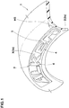
- a tyre 1 in this embodiment is provided with one or more mark indicating portions 3 in at least one of sidewall portions 2.
- Each of the mark indicating portions 3 is provided with a reference surface (X) provided on a surface (2s) of a respective one of the sidewall portions 2 and one or more marks 4 formed on the reference surface (x).
- each of the mark indicating portions 3 is provided with a base portion 5 which projects stepwise from the surface (2s) of a respective one of the sidewall portions 2 at a constant height (H5) (that is, a top surface of the base portion is not inclined with respect to the surface (2s)) and a surface (5s) of the base portion 5 forms the reference surface (X).
- Each of the marks 4 is a letter, a symbol, a figure, and the like for representing the manufacturer name, brand name, size, and the like of the tyre, and in this embodiment, a case is shown in which a brand name consisting of a plurality of the marks 4 is formed on the reference surface (X).
- a surface (4s) of each of the marks 4 is provided with a ridge line 10 extending obliquely with respect to a tyre radial direction, a first surface portion 11 positioned on an outer side in the tyre radial direction of the ridge line 10, and a second surface portion 12 positioned on an inner side in the tyre radial direction of the ridge line 10.
- the ridge line 10 in this embodiment has a constant height (Hx) from the reference surface (X). It is preferred that the height (Hx) is larger than the height (H5) of the base portion 5 from the surface (2s) of a respective one of the sidewall portions 2 from the point of view of the legibility.
- the height (Hx) may vary in a length direction of the ridge line 10. In this case, it is preferred that the ridge line 10 is formed in an arcuate shape in which the height (Hx) is decreased gradually and smoothly from a center in the length direction toward both ends thereof.
- the ridge line 10 extends diagonally on the surface (4s) of each of the marks 4.
- extending diagonally is defined as follows.
- a parallelogram (A) when the smallest parallelogram among parallelograms (including the rectangles) surrounding one of the marks 4 is defined as a parallelogram (A), extending diagonally means extending in a direction so as to connect between diagonal neighborhoods (B) of the parallelogram (A).
- the parallelogram (A) includes an upper side (a1) and a lower side (a2) extending in the tyre circumferential direction.
- each of the diagonal neighborhoods (B) means a range in which a distance from a respective one of diagonals (b) of the parallelogram (A) is 10% or less of a length of a diagonal line (c).
- the ridge line 10 in this embodiment is formed in an arcuate curved line in a front view of each of the marks 4. However, it can also be formed in a straight line.
- each of the first surface portion 11 and the second surface portion 12 is inclined in a direction in which a height thereof from the reference surface (X) is decreased as it goes away from the ridge line 10.
- the ridge line 10 is inclined toward upper right ( Fig. 3A )
- the first surface portion 11 is inclined toward an upper left direction F1
- the second surface portion 12 is inclined toward a lower right direction F2.
- the first surface portion 11 and the second surface portion 12 are inclined with respect to both the tyre circumferential direction and the tyre radial direction.
- the first surface portion 11 and the second surface portion 12 have components that are inclined in opposite directions (upward and downward) to each other with respect to the tyre radial direction, therefore, irrespective of the positions on the surfaces (2s) of the sidewall portions 2 at which the marks 4 are arranged, the surfaces (4s) of the marks 4 reflect light, thereby, it is possible that the legibility is increased.
- the first surface portion 11 and the second surface portion 12 have components that are inclined in opposite directions to each other with respect to the tyre circumferential direction as well, therefore, the reflecting surfaces appear changing and sparkling when the tyre rotates, thereby, it is possible that quality of products appearance is improved.
- each of the surfaces (4s) is inclined in a mountain shape, therefore, a change is given to the appearance of the marks 4, thereby, the stereoscopic effect is increased. Therefore, it is possible that the design property and the legibility are improved.
- Each of the first surface portion 11 and the second surface portion 12 can be formed as a flat surface. However, it can also be formed as a curved surface curved in a concave manner or a convex manner, for example. Note that although not shown, in a cross section taken orthogonal to the ridge line 10, it is preferred that an inclination angle of the first surface portion 11 with respect to the reference surface (X) is the same as an inclination angle of the second surface portion 12 with respect to the reference surface (x) from a point of view of the design property.
- a ratio (J1/J2) between an area (J1) of the first surface portion 11 and an area (J2) of the second surface portion 12 is in a range of from 0.7 to 1.3 when the surface (4s) is viewed from the front.
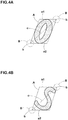
- each of the mark indicating portions 3 as shown in Figs. 5A and 5B , it is preferred that a surface (S) which is either the reference surface (X) or the surface (4s) of each of the marks 4 is provided with a plurality of small protruding portions 15 each protruding from the surface (s).
- a case where each of the small protruding portions 15 is a truncated conical protrusion 16 having a smaller diameter on a side of an upper end thereof is shown.
- each of the truncated conical protrusions 16 has a maximum diameter (D1) in the range of from 50 to 1000 micro meters and a protruding height (H1) from the surface (S) in the range of from 50 to 1000 micro meters, and that a distance (L1) between centers of the small protruding portions 15 adjacent to each other is in the range of from 200 to 1000 micro meters.
- the truncated conical protrusions 16 configured as such irregularly reflect light and make the surface (S) (the reference surface (X) or the surface (4s) of the mark 4) look black. Thereby, it is possible that the contour shapes of the marks 4 are made clearer, therefore, it is possible that the legibility of the marks 4 is further improved.
- the truncated conical protrusions 16 are arranged in a grid pattern, but they may be arranged in a staggered pattern, or may be randomly arranged as long as the distance (L1) satisfies the above range.
- Figs, 6A and 6B show another embodiment of the small protruding portions 15.
- each of the small protruding portions 15 is a rib-shaped protrusion 17 having a trapezoidal cross section with a thickness thereof decreasing toward an upper end thereof.
- the rib-shaped protrusions 17 can be arranged parallel to each other as shown in Fig, 6A , or they can be arranged so as not to be parallel to each other (non-parallel) as shown in Fig. 6B .
- each of the rib-shaped protrusions 17 has a maximum thickness (D2) in a range of from 20 to 1000 micro meters and a protruding height (H2) in a range of from 200 to 500 micro meters, and that a distance (L2) between the rib-shaped protrusions 17 adjacent to each other is in a range of from 10 to 800 micro meters.
- D2 maximum thickness
- H2 protruding height
- L2 distance between the rib-shaped protrusions 17 adjacent to each other is in a range of from 10 to 800 micro meters.
- an average value of a maximum value (L2max) and a minimum value (L2min) of the distance (L2) is in a range of from 10 to 800 micro meters.
- the rib-shaped protrusion 17 irregularly reflect light and make the surface (S) (the reference surface (X) or the surface (4s) of the mark 4) look black. Thereby, it is possible that the contour shapes of the marks 4 are made clearer, therefore, it is possible that the legibility of the marks 4 is further improved.
- each of the mark indicating portions 3 it is possible that the marks 4 are formed directly on the surface (2s) of a respective one of the sidewall portions 2 without having the base portion 5 formed thereon.
- the surface (2s) of the sidewall portion 2 forms the reference surface (x).
- the surface (2s) of each of the sidewall portions 2 is provided with a rib and the like having a small height and surrounding a respective one of the mark indicating portions 3.
- Tyres provided with the mark indicating portions on the surface of the sidewall portions were made by way of test according to the specifications listed in Table 1, and then the legibility of the marks was compared.
- the ridge line extended diagonally in each of the marks.
- the height (Hx) of each of the ridge lines was constant, and in a plan view, each of the ridge lines was formed in an arcuate curved line.
- the first surface portion and the second surface portion which were divided by the ridge line were each formed as a flat surface.
- no ridge line was provided and the surface of each of the marks was formed as a flat surface.
- the small protruding portions were formed on the surfaces of the marks.
- the small protruding portions were the truncated conical protrusions each having the maximum diameter (D1) of 320 micro meters and the protruding height (H1) of 500 micro meters, and the distance (L1) was 400 micro meters
- the small protruding portions were the rib-shaped protrusions each having the maximum thickness (D2) of 160 micro meters and the protruding height (H2) of 200 micro meters, and the distance (L2) was 200 micro meters.
- legibility was evaluated by a visual observation and the evaluation is indicated by an index based on the Reference 1 being 100, wherein a larger numerical value is better.
Landscapes
- Engineering & Computer Science (AREA)
- Mechanical Engineering (AREA)
- Tires In General (AREA)
Claims (11)
- Reifen (1) mit einem Seitenwandabschnitt (2), der mit einem Markierungsanzeigeabschnitt (3) versehen ist, der eine oder mehrere Markierungen (4) aufweist, die Buchstaben und Symbole sind, die den Herstellernamen, Markennamen, die Größe und dergleichen des Reifens (1) anzeigen, wobeider Markierungsanzeigeabschnitt (3) eine Bezugsoberfläche (X) umfasst, die auf einer Oberfläche (2s) des Seitenwandabschnitts (2) vorgesehen ist, und die eine oder mehreren Markierungen (4) auf der Bezugsoberfläche (X) auf eine konvexe Weise ausgebildet sind, und,eine Oberfläche (4s) jeder Markierung (4) mit einer Gratlinie (10) versehen ist, die sich schräg in Bezug auf eine radiale Richtung des Reifens erstreckt, wobei ein erster Oberflächenabschnitt (11) auf einer äußeren Seite in der radialen Richtung des Reifens der Gratlinie (10) positioniert ist, und ein zweiter Oberflächenabschnitt (12) auf einer inneren Seite in der radialen Richtung des Reifens der Gratlinie (10) positioniert ist, undein jeder von dem ersten Oberflächenabschnitt (11) und dem zweiten Oberflächenabschnitt (12) in einer Richtung geneigt ist, in der seine Höhe von der Bezugsfläche (X) mit zunehmender Entfernung von der Gratlinie (10) abnimmt,dadurch gekennzeichnet, dasswenn das kleinstmögliche Parallelogramm (A) so gezeichnet wird, dass es jede Markierung (4) umgibt, das Parallelogramm (A) eine obere und eine untere Seite (a1, a2), die sich jeweils in Reifenumfangsrichtung erstrecken, und eine diagonale Linie (c), die gegenüberliegende Ecken (b) des Parallelogramms (A) verbindet, umfasst, und dassdie Gratlinie (10) sich so in einer Richtung erstreckt, dass sie eine Verbindung zwischen den Ecken (b) herstellt.
- Reifen (1) nach Anspruch 1, wobei eine Höhe der Gratlinie (10) von der Bezugsoberfläche (X) konstant ist.
- Reifen (1) nach Anspruch 1 oder 2, wobei die Gratlinie (10) sich entlang der Diagonalen (c) des Parallelogramms (A) erstreckt.
- Reifen (1) nach einem der Ansprüche 1 bis 3, wobei die Gratlinie (10) eine gerade Linie oder eine bogenförmige gekrümmte Linie ist.
- Reifen (1) nach einem der Ansprüche 1 bis 4, wobei sowohl der erste Oberflächenabschnitt (11) als auch der zweite Oberflächenabschnitt (12) eine ebene Oberfläche oder eine konkav oder konvex gekrümmte Oberfläche ist.
- Reifen (1) nach einem der Ansprüche 1 bis 5, wobei in dem Markierungsanzeigeabschnitt (3) entweder die Bezugsoberfläche (X) oder die Oberfläche jeder Markierung (4) mit einer Vielzahl kleiner vorspringender Abschnitte (15) versehen ist.
- Reifen (1) nach Anspruch 6, wobei jeder der kleinen vorspringenden Abschnitte (15) ein kegelstumpfförmiger Vorsprung (16) ist, der einen kleineren Durchmesser auf einer Seite seines oberen Endes aufweist.
- Reifen (1) nach Anspruch 7, wobeijeder der kegelstumpfförmigen Vorsprünge (16) einen maximalen Durchmesser (D1) in einem Bereich von 50 bis 1000 Mikrometern und eine Vorsprungshöhe (H1) in einem Bereich von 50 bis 1000 Mikrometern aufweist, undein Abstand (L1) zwischen den Mittelpunkten der benachbarten kegelstumpfförmigen Vorsprünge (16) in einem Bereich von 200 bis 1000 Mikrometern liegt.
- Reifen (1) nach Anspruch 6, wobeiein jeder der kleinen vorspringenden Abschnitte (15) ein rippenförmiger Vorsprung (17) mit einem trapezförmigen Querschnitt ist, dessen Dicke zu einem oberen Ende hin abnimmt, unddie rippenförmigen Vorsprünge (17) parallel zueinander oder in nicht paralleler Weise angeordnet sind.
- Reifen (1) nach Anspruch 9, wobeiein jeder der rippenförmigen Vorsprünge (17) eine maximale Dicke (D2) in einem Bereich von 20 bis 1000 Mikrometern und eine Vorsprungshöhe (H2) in einem Bereich von 200 bis 500 Mikrometern aufweist, undein Abstand (L2) zwischen den benachbarten rippenförmigen Vorsprüngen (17) in einem Bereich von 10 bis 800 Mikrometern liegt.
- Reifen (1) nach einem der Ansprüche 1 bis 10, wobeider Markierungsanzeigeabschnitt (3) mit einem Basisabschnitt (5) versehen ist, der von der Oberfläche des Seitenwandabschnitts (2) in einer konstanten Höhe vorspringt, undeine Oberfläche (5s) des Basisabschnitts (5) die Bezugsoberfläche (X) bildet.
Applications Claiming Priority (1)
| Application Number | Priority Date | Filing Date | Title |
|---|---|---|---|
| JP2018058489A JP7087538B2 (ja) | 2018-03-26 | 2018-03-26 | タイヤ |
Publications (2)
| Publication Number | Publication Date |
|---|---|
| EP3546251A1 EP3546251A1 (de) | 2019-10-02 |
| EP3546251B1 true EP3546251B1 (de) | 2021-10-27 |
Family
ID=65686738
Family Applications (1)
| Application Number | Title | Priority Date | Filing Date |
|---|---|---|---|
| EP19160604.5A Active EP3546251B1 (de) | 2018-03-26 | 2019-03-04 | Reifen |
Country Status (3)
| Country | Link |
|---|---|
| US (2) | US11607916B2 (de) |
| EP (1) | EP3546251B1 (de) |
| JP (1) | JP7087538B2 (de) |
Families Citing this family (6)
| Publication number | Priority date | Publication date | Assignee | Title |
|---|---|---|---|---|
| JP7482622B2 (ja) * | 2019-12-06 | 2024-05-14 | Toyo Tire株式会社 | 空気入りタイヤ |
| JP7673386B2 (ja) * | 2020-11-20 | 2025-05-09 | 住友ゴム工業株式会社 | タイヤ |
| USD1001726S1 (en) * | 2021-04-19 | 2023-10-17 | Continental Reifen Deustschland Gmbh | Sidewall of a tire with graphic symbol |
| USD1000372S1 (en) * | 2021-04-19 | 2023-10-03 | Continental Reifen Deutschland Gmbh | Sidewall of a tire with graphic symbol |
| USD999722S1 (en) * | 2021-04-19 | 2023-09-26 | Continental Reifen Deutschland Gmbh | Sidewall of a tire with graphic symbol |
| USD1000371S1 (en) * | 2021-04-19 | 2023-10-03 | Continental Reifen Deutschland Gmbh | Sidewall of a tire with graphic symbol |
Family Cites Families (21)
| Publication number | Priority date | Publication date | Assignee | Title |
|---|---|---|---|---|
| AT397373B (de) * | 1990-05-14 | 1994-03-25 | Semperit Ag | Fahrzeugreifen |
| AU641063B2 (en) * | 1990-12-10 | 1993-09-09 | Uniroyal Goodrich Licensing Services, Inc. | Character for a tire |
| IT1263919B (it) * | 1993-02-16 | 1996-09-05 | Pirelli | Pneumatico per ruote di veicoli, presentante in corrispondenza dei fianchi una fascia anulare superficialmente lavorata |
| JP3007825B2 (ja) * | 1995-09-28 | 2000-02-07 | 住友ゴム工業株式会社 | 空気入りタイヤ |
| JPH09226328A (ja) * | 1996-02-23 | 1997-09-02 | Bridgestone Corp | 多数のリッジよりなる標章を備えた空気入りタイヤ |
| JP3652809B2 (ja) * | 1996-09-13 | 2005-05-25 | 株式会社ブリヂストン | 空気入りタイヤ |
| EP1310384B1 (de) * | 2001-11-08 | 2014-01-29 | Sumitomo Rubber Industries, Ltd. | Fahrzeugreifen |
| US7232498B2 (en) * | 2004-08-13 | 2007-06-19 | The Goodyear Tire & Rubber Company | Tire with raised indicia |
| JP2006224704A (ja) * | 2005-02-15 | 2006-08-31 | Bridgestone Corp | 空気入りタイヤ |
| JP4956948B2 (ja) * | 2005-09-22 | 2012-06-20 | 横浜ゴム株式会社 | タイヤ加硫用金型、空気入りタイヤの製造方法及び空気入りタイヤ |
| US20080283169A1 (en) * | 2007-02-22 | 2008-11-20 | Toyo Tire & Rubber Co., Ltd. | Pneumatic Tire |
| JP5230229B2 (ja) * | 2007-04-05 | 2013-07-10 | 東洋ゴム工業株式会社 | 空気入りタイヤ |
| JP5160345B2 (ja) * | 2008-08-26 | 2013-03-13 | 東洋ゴム工業株式会社 | 空気入りタイヤ |
| JP4687811B2 (ja) * | 2009-04-10 | 2011-05-25 | 横浜ゴム株式会社 | 空気入りタイヤ |
| FR2950566B1 (fr) * | 2009-09-28 | 2011-08-26 | Michelin Soc Tech | Motif de pneumatique a fort contraste et procede d'obtention |
| US20120097304A1 (en) * | 2010-10-22 | 2012-04-26 | The Yokohama Rubber Co., Ltd. | Pneumatic tire |
| JP2012116217A (ja) * | 2010-11-29 | 2012-06-21 | Bridgestone Corp | タイヤ |
| JP5520334B2 (ja) * | 2012-04-04 | 2014-06-11 | 住友ゴム工業株式会社 | 空気入りタイヤ |
| JP5886914B2 (ja) * | 2014-09-01 | 2016-03-16 | 住友ゴム工業株式会社 | 空気入りタイヤ |
| JP6411949B2 (ja) * | 2015-06-05 | 2018-10-24 | 株式会社ブリヂストン | タイヤ |
| JP6597142B2 (ja) * | 2015-10-01 | 2019-10-30 | 横浜ゴム株式会社 | 空気入りタイヤ |
-
2018
- 2018-03-26 JP JP2018058489A patent/JP7087538B2/ja active Active
-
2019
- 2019-03-04 EP EP19160604.5A patent/EP3546251B1/de active Active
- 2019-03-05 US US16/292,637 patent/US11607916B2/en active Active
-
2023
- 2023-02-08 US US18/107,233 patent/US20230182507A1/en not_active Abandoned
Non-Patent Citations (1)
| Title |
|---|
| None * |
Also Published As
| Publication number | Publication date |
|---|---|
| US20230182507A1 (en) | 2023-06-15 |
| JP7087538B2 (ja) | 2022-06-21 |
| US20190291516A1 (en) | 2019-09-26 |
| EP3546251A1 (de) | 2019-10-02 |
| JP2019167066A (ja) | 2019-10-03 |
| US11607916B2 (en) | 2023-03-21 |
Similar Documents
| Publication | Publication Date | Title |
|---|---|---|
| EP3546251B1 (de) | Reifen | |
| EP3533633B1 (de) | Reifen | |
| CN108602397B (zh) | 轮胎 | |
| US8006732B2 (en) | Pneumatic tire with sidewall decorative band | |
| CN111572288B (zh) | 轮胎 | |
| EP2781376A1 (de) | Luftreifen | |
| EP3533635B1 (de) | Reifen | |
| US20190030959A1 (en) | Tire | |
| EP3489040A1 (de) | Reifen | |
| EP3546252B1 (de) | Reifen | |
| EP3533638B1 (de) | Reifen | |
| EP3666555A1 (de) | Reifen | |
| EP3511180B1 (de) | Reifen | |
| EP3533636B1 (de) | Reifen | |
| EP3533634B1 (de) | Reifen | |
| US11097574B2 (en) | Tyre | |
| JP2020131763A (ja) | タイヤ |
Legal Events
| Date | Code | Title | Description |
|---|---|---|---|
| PUAI | Public reference made under article 153(3) epc to a published international application that has entered the european phase |
Free format text: ORIGINAL CODE: 0009012 |
|
| STAA | Information on the status of an ep patent application or granted ep patent |
Free format text: STATUS: THE APPLICATION HAS BEEN PUBLISHED |
|
| AK | Designated contracting states |
Kind code of ref document: A1 Designated state(s): AL AT BE BG CH CY CZ DE DK EE ES FI FR GB GR HR HU IE IS IT LI LT LU LV MC MK MT NL NO PL PT RO RS SE SI SK SM TR |
|
| AX | Request for extension of the european patent |
Extension state: BA ME |
|
| STAA | Information on the status of an ep patent application or granted ep patent |
Free format text: STATUS: REQUEST FOR EXAMINATION WAS MADE |
|
| STAA | Information on the status of an ep patent application or granted ep patent |
Free format text: STATUS: EXAMINATION IS IN PROGRESS |
|
| 17P | Request for examination filed |
Effective date: 20200227 |
|
| RBV | Designated contracting states (corrected) |
Designated state(s): AL AT BE BG CH CY CZ DE DK EE ES FI FR GB GR HR HU IE IS IT LI LT LU LV MC MK MT NL NO PL PT RO RS SE SI SK SM TR |
|
| 17Q | First examination report despatched |
Effective date: 20200414 |
|
| GRAP | Despatch of communication of intention to grant a patent |
Free format text: ORIGINAL CODE: EPIDOSNIGR1 |
|
| STAA | Information on the status of an ep patent application or granted ep patent |
Free format text: STATUS: GRANT OF PATENT IS INTENDED |
|
| INTG | Intention to grant announced |
Effective date: 20210112 |
|
| GRAJ | Information related to disapproval of communication of intention to grant by the applicant or resumption of examination proceedings by the epo deleted |
Free format text: ORIGINAL CODE: EPIDOSDIGR1 |
|
| STAA | Information on the status of an ep patent application or granted ep patent |
Free format text: STATUS: EXAMINATION IS IN PROGRESS |
|
| INTC | Intention to grant announced (deleted) | ||
| GRAP | Despatch of communication of intention to grant a patent |
Free format text: ORIGINAL CODE: EPIDOSNIGR1 |
|
| STAA | Information on the status of an ep patent application or granted ep patent |
Free format text: STATUS: GRANT OF PATENT IS INTENDED |
|
| INTG | Intention to grant announced |
Effective date: 20210611 |
|
| GRAS | Grant fee paid |
Free format text: ORIGINAL CODE: EPIDOSNIGR3 |
|
| GRAA | (expected) grant |
Free format text: ORIGINAL CODE: 0009210 |
|
| STAA | Information on the status of an ep patent application or granted ep patent |
Free format text: STATUS: THE PATENT HAS BEEN GRANTED |
|
| AK | Designated contracting states |
Kind code of ref document: B1 Designated state(s): AL AT BE BG CH CY CZ DE DK EE ES FI FR GB GR HR HU IE IS IT LI LT LU LV MC MK MT NL NO PL PT RO RS SE SI SK SM TR |
|
| REG | Reference to a national code |
Ref country code: GB Ref legal event code: FG4D |
|
| REG | Reference to a national code |
Ref country code: CH Ref legal event code: EP |
|
| REG | Reference to a national code |
Ref country code: AT Ref legal event code: REF Ref document number: 1441469 Country of ref document: AT Kind code of ref document: T Effective date: 20211115 |
|
| REG | Reference to a national code |
Ref country code: DE Ref legal event code: R096 Ref document number: 602019008589 Country of ref document: DE |
|
| REG | Reference to a national code |
Ref country code: IE Ref legal event code: FG4D |
|
| REG | Reference to a national code |
Ref country code: LT Ref legal event code: MG9D |
|
| REG | Reference to a national code |
Ref country code: NL Ref legal event code: MP Effective date: 20211027 |
|
| REG | Reference to a national code |
Ref country code: AT Ref legal event code: MK05 Ref document number: 1441469 Country of ref document: AT Kind code of ref document: T Effective date: 20211027 |
|
| PG25 | Lapsed in a contracting state [announced via postgrant information from national office to epo] |
Ref country code: RS Free format text: LAPSE BECAUSE OF FAILURE TO SUBMIT A TRANSLATION OF THE DESCRIPTION OR TO PAY THE FEE WITHIN THE PRESCRIBED TIME-LIMIT Effective date: 20211027 Ref country code: LT Free format text: LAPSE BECAUSE OF FAILURE TO SUBMIT A TRANSLATION OF THE DESCRIPTION OR TO PAY THE FEE WITHIN THE PRESCRIBED TIME-LIMIT Effective date: 20211027 Ref country code: FI Free format text: LAPSE BECAUSE OF FAILURE TO SUBMIT A TRANSLATION OF THE DESCRIPTION OR TO PAY THE FEE WITHIN THE PRESCRIBED TIME-LIMIT Effective date: 20211027 Ref country code: BG Free format text: LAPSE BECAUSE OF FAILURE TO SUBMIT A TRANSLATION OF THE DESCRIPTION OR TO PAY THE FEE WITHIN THE PRESCRIBED TIME-LIMIT Effective date: 20220127 Ref country code: AT Free format text: LAPSE BECAUSE OF FAILURE TO SUBMIT A TRANSLATION OF THE DESCRIPTION OR TO PAY THE FEE WITHIN THE PRESCRIBED TIME-LIMIT Effective date: 20211027 |
|
| PG25 | Lapsed in a contracting state [announced via postgrant information from national office to epo] |
Ref country code: IS Free format text: LAPSE BECAUSE OF FAILURE TO SUBMIT A TRANSLATION OF THE DESCRIPTION OR TO PAY THE FEE WITHIN THE PRESCRIBED TIME-LIMIT Effective date: 20220227 Ref country code: SE Free format text: LAPSE BECAUSE OF FAILURE TO SUBMIT A TRANSLATION OF THE DESCRIPTION OR TO PAY THE FEE WITHIN THE PRESCRIBED TIME-LIMIT Effective date: 20211027 Ref country code: PT Free format text: LAPSE BECAUSE OF FAILURE TO SUBMIT A TRANSLATION OF THE DESCRIPTION OR TO PAY THE FEE WITHIN THE PRESCRIBED TIME-LIMIT Effective date: 20220228 Ref country code: PL Free format text: LAPSE BECAUSE OF FAILURE TO SUBMIT A TRANSLATION OF THE DESCRIPTION OR TO PAY THE FEE WITHIN THE PRESCRIBED TIME-LIMIT Effective date: 20211027 Ref country code: NO Free format text: LAPSE BECAUSE OF FAILURE TO SUBMIT A TRANSLATION OF THE DESCRIPTION OR TO PAY THE FEE WITHIN THE PRESCRIBED TIME-LIMIT Effective date: 20220127 Ref country code: NL Free format text: LAPSE BECAUSE OF FAILURE TO SUBMIT A TRANSLATION OF THE DESCRIPTION OR TO PAY THE FEE WITHIN THE PRESCRIBED TIME-LIMIT Effective date: 20211027 Ref country code: LV Free format text: LAPSE BECAUSE OF FAILURE TO SUBMIT A TRANSLATION OF THE DESCRIPTION OR TO PAY THE FEE WITHIN THE PRESCRIBED TIME-LIMIT Effective date: 20211027 Ref country code: HR Free format text: LAPSE BECAUSE OF FAILURE TO SUBMIT A TRANSLATION OF THE DESCRIPTION OR TO PAY THE FEE WITHIN THE PRESCRIBED TIME-LIMIT Effective date: 20211027 Ref country code: GR Free format text: LAPSE BECAUSE OF FAILURE TO SUBMIT A TRANSLATION OF THE DESCRIPTION OR TO PAY THE FEE WITHIN THE PRESCRIBED TIME-LIMIT Effective date: 20220128 Ref country code: ES Free format text: LAPSE BECAUSE OF FAILURE TO SUBMIT A TRANSLATION OF THE DESCRIPTION OR TO PAY THE FEE WITHIN THE PRESCRIBED TIME-LIMIT Effective date: 20211027 |
|
| REG | Reference to a national code |
Ref country code: DE Ref legal event code: R097 Ref document number: 602019008589 Country of ref document: DE |
|
| PG25 | Lapsed in a contracting state [announced via postgrant information from national office to epo] |
Ref country code: SM Free format text: LAPSE BECAUSE OF FAILURE TO SUBMIT A TRANSLATION OF THE DESCRIPTION OR TO PAY THE FEE WITHIN THE PRESCRIBED TIME-LIMIT Effective date: 20211027 Ref country code: SK Free format text: LAPSE BECAUSE OF FAILURE TO SUBMIT A TRANSLATION OF THE DESCRIPTION OR TO PAY THE FEE WITHIN THE PRESCRIBED TIME-LIMIT Effective date: 20211027 Ref country code: RO Free format text: LAPSE BECAUSE OF FAILURE TO SUBMIT A TRANSLATION OF THE DESCRIPTION OR TO PAY THE FEE WITHIN THE PRESCRIBED TIME-LIMIT Effective date: 20211027 Ref country code: EE Free format text: LAPSE BECAUSE OF FAILURE TO SUBMIT A TRANSLATION OF THE DESCRIPTION OR TO PAY THE FEE WITHIN THE PRESCRIBED TIME-LIMIT Effective date: 20211027 Ref country code: DK Free format text: LAPSE BECAUSE OF FAILURE TO SUBMIT A TRANSLATION OF THE DESCRIPTION OR TO PAY THE FEE WITHIN THE PRESCRIBED TIME-LIMIT Effective date: 20211027 Ref country code: CZ Free format text: LAPSE BECAUSE OF FAILURE TO SUBMIT A TRANSLATION OF THE DESCRIPTION OR TO PAY THE FEE WITHIN THE PRESCRIBED TIME-LIMIT Effective date: 20211027 |
|
| PLBE | No opposition filed within time limit |
Free format text: ORIGINAL CODE: 0009261 |
|
| STAA | Information on the status of an ep patent application or granted ep patent |
Free format text: STATUS: NO OPPOSITION FILED WITHIN TIME LIMIT |
|
| 26N | No opposition filed |
Effective date: 20220728 |
|
| PG25 | Lapsed in a contracting state [announced via postgrant information from national office to epo] |
Ref country code: MC Free format text: LAPSE BECAUSE OF FAILURE TO SUBMIT A TRANSLATION OF THE DESCRIPTION OR TO PAY THE FEE WITHIN THE PRESCRIBED TIME-LIMIT Effective date: 20211027 Ref country code: AL Free format text: LAPSE BECAUSE OF FAILURE TO SUBMIT A TRANSLATION OF THE DESCRIPTION OR TO PAY THE FEE WITHIN THE PRESCRIBED TIME-LIMIT Effective date: 20211027 |
|
| REG | Reference to a national code |
Ref country code: CH Ref legal event code: PL |
|
| PG25 | Lapsed in a contracting state [announced via postgrant information from national office to epo] |
Ref country code: SI Free format text: LAPSE BECAUSE OF FAILURE TO SUBMIT A TRANSLATION OF THE DESCRIPTION OR TO PAY THE FEE WITHIN THE PRESCRIBED TIME-LIMIT Effective date: 20211027 |
|
| REG | Reference to a national code |
Ref country code: BE Ref legal event code: MM Effective date: 20220331 |
|
| PG25 | Lapsed in a contracting state [announced via postgrant information from national office to epo] |
Ref country code: LU Free format text: LAPSE BECAUSE OF NON-PAYMENT OF DUE FEES Effective date: 20220304 Ref country code: LI Free format text: LAPSE BECAUSE OF NON-PAYMENT OF DUE FEES Effective date: 20220331 Ref country code: IE Free format text: LAPSE BECAUSE OF NON-PAYMENT OF DUE FEES Effective date: 20220304 Ref country code: CH Free format text: LAPSE BECAUSE OF NON-PAYMENT OF DUE FEES Effective date: 20220331 |
|
| PG25 | Lapsed in a contracting state [announced via postgrant information from national office to epo] |
Ref country code: BE Free format text: LAPSE BECAUSE OF NON-PAYMENT OF DUE FEES Effective date: 20220331 |
|
| PG25 | Lapsed in a contracting state [announced via postgrant information from national office to epo] |
Ref country code: IT Free format text: LAPSE BECAUSE OF FAILURE TO SUBMIT A TRANSLATION OF THE DESCRIPTION OR TO PAY THE FEE WITHIN THE PRESCRIBED TIME-LIMIT Effective date: 20211027 |
|
| P01 | Opt-out of the competence of the unified patent court (upc) registered |
Effective date: 20230510 |
|
| GBPC | Gb: european patent ceased through non-payment of renewal fee |
Effective date: 20230304 |
|
| PG25 | Lapsed in a contracting state [announced via postgrant information from national office to epo] |
Ref country code: GB Free format text: LAPSE BECAUSE OF NON-PAYMENT OF DUE FEES Effective date: 20230304 |
|
| PG25 | Lapsed in a contracting state [announced via postgrant information from national office to epo] |
Ref country code: GB Free format text: LAPSE BECAUSE OF NON-PAYMENT OF DUE FEES Effective date: 20230304 |
|
| PG25 | Lapsed in a contracting state [announced via postgrant information from national office to epo] |
Ref country code: MK Free format text: LAPSE BECAUSE OF FAILURE TO SUBMIT A TRANSLATION OF THE DESCRIPTION OR TO PAY THE FEE WITHIN THE PRESCRIBED TIME-LIMIT Effective date: 20211027 Ref country code: CY Free format text: LAPSE BECAUSE OF FAILURE TO SUBMIT A TRANSLATION OF THE DESCRIPTION OR TO PAY THE FEE WITHIN THE PRESCRIBED TIME-LIMIT Effective date: 20211027 |
|
| PG25 | Lapsed in a contracting state [announced via postgrant information from national office to epo] |
Ref country code: HU Free format text: LAPSE BECAUSE OF FAILURE TO SUBMIT A TRANSLATION OF THE DESCRIPTION OR TO PAY THE FEE WITHIN THE PRESCRIBED TIME-LIMIT; INVALID AB INITIO Effective date: 20190304 |
|
| PG25 | Lapsed in a contracting state [announced via postgrant information from national office to epo] |
Ref country code: MT Free format text: LAPSE BECAUSE OF FAILURE TO SUBMIT A TRANSLATION OF THE DESCRIPTION OR TO PAY THE FEE WITHIN THE PRESCRIBED TIME-LIMIT Effective date: 20211027 |
|
| PG25 | Lapsed in a contracting state [announced via postgrant information from national office to epo] |
Ref country code: TR Free format text: LAPSE BECAUSE OF FAILURE TO SUBMIT A TRANSLATION OF THE DESCRIPTION OR TO PAY THE FEE WITHIN THE PRESCRIBED TIME-LIMIT Effective date: 20211027 |
|
| PGFP | Annual fee paid to national office [announced via postgrant information from national office to epo] |
Ref country code: DE Payment date: 20260128 Year of fee payment: 8 |
|
| PGFP | Annual fee paid to national office [announced via postgrant information from national office to epo] |
Ref country code: FR Payment date: 20260209 Year of fee payment: 8 |