EP3546324B1 - Dispositif pare-chocs pour un véhicule automobile - Google Patents
Dispositif pare-chocs pour un véhicule automobile Download PDFInfo
- Publication number
- EP3546324B1 EP3546324B1 EP19161531.9A EP19161531A EP3546324B1 EP 3546324 B1 EP3546324 B1 EP 3546324B1 EP 19161531 A EP19161531 A EP 19161531A EP 3546324 B1 EP3546324 B1 EP 3546324B1
- Authority
- EP
- European Patent Office
- Prior art keywords
- crash box
- flange plate
- box flange
- receptacle
- crash
- Prior art date
- Legal status (The legal status is an assumption and is not a legal conclusion. Google has not performed a legal analysis and makes no representation as to the accuracy of the status listed.)
- Active
Links
Images




Classifications
-
- B—PERFORMING OPERATIONS; TRANSPORTING
- B60—VEHICLES IN GENERAL
- B60D—VEHICLE CONNECTIONS
- B60D1/00—Traction couplings; Hitches; Draw-gear; Towing devices
- B60D1/14—Draw-gear or towing devices characterised by their type
-
- B—PERFORMING OPERATIONS; TRANSPORTING
- B60—VEHICLES IN GENERAL
- B60R—VEHICLES, VEHICLE FITTINGS, OR VEHICLE PARTS, NOT OTHERWISE PROVIDED FOR
- B60R19/00—Wheel guards; Radiator guards, e.g. grilles; Obstruction removers; Fittings damping bouncing force in collisions
- B60R19/02—Bumpers, i.e. impact receiving or absorbing members for protecting vehicles or fending off blows from other vehicles or objects
- B60R19/24—Arrangements for mounting bumpers on vehicles
- B60R19/26—Arrangements for mounting bumpers on vehicles comprising yieldable mounting means
-
- B—PERFORMING OPERATIONS; TRANSPORTING
- B60—VEHICLES IN GENERAL
- B60D—VEHICLE CONNECTIONS
- B60D1/00—Traction couplings; Hitches; Draw-gear; Towing devices
- B60D1/48—Traction couplings; Hitches; Draw-gear; Towing devices characterised by the mounting
- B60D1/56—Traction couplings; Hitches; Draw-gear; Towing devices characterised by the mounting securing to the vehicle bumper
-
- B—PERFORMING OPERATIONS; TRANSPORTING
- B60—VEHICLES IN GENERAL
- B60D—VEHICLE CONNECTIONS
- B60D1/00—Traction couplings; Hitches; Draw-gear; Towing devices
- B60D1/48—Traction couplings; Hitches; Draw-gear; Towing devices characterised by the mounting
- B60D1/56—Traction couplings; Hitches; Draw-gear; Towing devices characterised by the mounting securing to the vehicle bumper
- B60D1/565—Traction couplings; Hitches; Draw-gear; Towing devices characterised by the mounting securing to the vehicle bumper having an eyelet
-
- B—PERFORMING OPERATIONS; TRANSPORTING
- B60—VEHICLES IN GENERAL
- B60R—VEHICLES, VEHICLE FITTINGS, OR VEHICLE PARTS, NOT OTHERWISE PROVIDED FOR
- B60R19/00—Wheel guards; Radiator guards, e.g. grilles; Obstruction removers; Fittings damping bouncing force in collisions
- B60R19/02—Bumpers, i.e. impact receiving or absorbing members for protecting vehicles or fending off blows from other vehicles or objects
- B60R19/24—Arrangements for mounting bumpers on vehicles
- B60R19/26—Arrangements for mounting bumpers on vehicles comprising yieldable mounting means
- B60R19/34—Arrangements for mounting bumpers on vehicles comprising yieldable mounting means destroyed upon impact, e.g. one-shot type
Definitions
- the invention relates to a bumper arrangement for a motor vehicle according to the preamble of claim 1.
- Such a bumper arrangement for a motor vehicle is for example in DE 10 2011 010 798 A1 shown.
- This bumper arrangement for a motor vehicle has a cross member on which crash boxes designed as a single-chamber hollow profile are arranged with one end on this cross member.
- crash box flange plates are arranged, with the aid of which the bumper arrangement can be arranged on a body or a chassis of a motor vehicle.
- a further flange plate is provided on which a sleeve-shaped hole element with an internal thread is arranged, in which a towing eye with a corresponding external thread can be detachably arranged.
- This entire flange plate is arranged between the crash box flange plate and the motor vehicle, the sleeve-shaped hole element of the flange plate protruding into the crash box through an opening in the crash box flange plate.
- a mounting opening is provided through which a corresponding towing eye can be inserted into the crash box and, by means of its external thread, engages in the internal thread of the sleeve-shaped hole element and can thus be connected to the bumper assembly.
- the towing eye then protrudes from the cross member so that the eye is freely accessible and a motor vehicle with such a bumper arrangement can be towed on it.
- a separate support element for the hole element which is arranged on the flange plate and made up of individual support flanges.
- bumper assemblies are known in which an integrated thread is used in a hollow chamber of an asymmetrically extruded crash box designed as a multi-chamber profile, the thread being arranged in the front or middle longitudinal section of the crash box.
- the problem with these bumper arrangements is poor folding behavior due to the corresponding threaded block.
- JP2012224099 A discloses a bumper assembly according to the preamble of claim 1.
- the bumper arrangement according to the invention for a motor vehicle has a cross member to which crash boxes are coupled, with crash box flange plates for fastening the crash boxes to a body or a chassis of a motor vehicle being arranged on the crash boxes opposite the cross member.
- a receptacle extending in the direction of the cross member is arranged non-positively and / or cohesively on at least one crash box flange plate, the receptacle being designed for the detachable arrangement of a towing device, such as a towing eye.
- the at least one crash box flange plate is designed as a hollow chamber profile, which is particularly advantageously designed in one piece.
- the bumper arrangement according to the invention now makes it possible to keep as few parts as possible in stock for the production of such a bumper arrangement, since the receptacle for the detachable arrangement of the towing device is arranged directly on the crash box flange plate, the crash box flange plate with the receptacle for the detachable arrangement of the towing device for assembly the bumper arrangement can be provided as a unitary, advantageously one-piece component. Alternatively, it is of course also possible to join the receptacle for the detachable arrangement of the towing device only when the bumper arrangement is assembled with the crash box flange plate.
- the non-positive, positive and / or cohesive connection of the receptacle for the detachable arrangement of a towing device with the crash box flange plate can take place by means of a welded connection, a screw connection or the like.
- the bumper arrangement according to the invention due to the design of the bumper arrangement according to the invention, no special consideration needs to be given to the smallest possible tolerance ranges in the receptacle and the crash boxes, since these are not directly coupled to one another.
- the arrangement of the receptacle on the crash box flange plate also ensures that the crash boxes themselves are not loaded when the motor vehicle is towed, since the receptacle for the detachable arrangement of the towing device is coupled directly to the body or the chassis of the motor vehicle via the crash box flange plate and then no stress on the crash boxes or impairment of the deformation behavior occurs.
- the receptacle is advantageously designed as a threaded sleeve with an internal thread.
- the at least one crash box flange plate is designed as a single-chamber hollow profile.
- Such single-chamber hollow profiles can be produced in a simple manner in terms of process engineering using sophisticated methods. The same also applies to the design of the at least one crash box flange plate as a multi-chamber hollow profile.
- Such hollow profiles also have very good rigidity, so that these crash box flange plates, which are designed as hollow chamber profiles, can also convert energy into deformation energy in addition to the crash boxes themselves in the event of a crash. A bending of the crash box flange plate due to tensile forces when towing or lashing the motor vehicle via the receptacle is prevented. This also increases the safety of the occupants of a motor vehicle with a bumper arrangement according to the invention.
- the at least one crash box flange plate has a front wall, a rear wall and two side walls connecting the front wall and the rear wall. With this configuration, a cavity is formed through the rear wall, the front wall and in the two side walls, in which the single-chamber or multi-chamber hollow profile is formed.
- the crash box flange plate is designed as a multi-chamber hollow profile
- at least one inner wall connecting the front wall and the rear wall is also provided within the crash box flange plate, which inner wall preferably extends in the same direction as the side walls.
- other inner walls can also be provided, which the Connect side walls to one another, but also extend in the same direction as the side walls.
- the rear wall has webs which protrude beyond the side walls.
- a crash box is attached to the front wall of the at least one crash box flange plate.
- the crash box flange plate essentially represents an extension of the crash box. Because it is designed as a hollow chamber profile, as already mentioned, it also contributes to energy absorption in the event of a crash, so that the safety of the vehicle occupants of a motor vehicle with a bumper arrangement according to the invention is increased again .
- crash box it is also possible to add a crash box to the rear wall of the crash box flange plate, in particular in the area of the webs of the rear wall protruding beyond the side walls.
- the hollow chamber of the crash box flange plate then extends into the corresponding crash box. This also makes it possible to implement a second level of force in the bumper system over the deformation length of the crash box.
- the crash box is joined to the front wall in such a way that the crash box is supported or rests against at least one of the side walls. This again results in a better and more stable connection between the crash box and the crash box flange plate. In particular when the crash box rests against both side walls, not only is an improved and more stable connection between the crash box and the crash box flange plate achieved.
- the at least one crash box flange plate is designed as an extrusion profile.
- Such a configuration of the crash box flange plate enables a crash box flange plate according to the invention to be easily manufactured as a one-piece component, which can be further processed accordingly, and significantly less logistics outlay claimed as a component formed from several individual parts.
- the crash boxes of the bumper arrangement according to the invention are designed on the one hand as a single-chamber hollow profile and on the other hand as a multi-chamber hollow profile.
- Such hollow profiles have proven themselves in crash boxes because they allow energy inputs to be absorbed in a particularly simple and effective manner with targeted deformation of the crash boxes, so that this results in a particularly good energy absorption capacity for the entire bumper arrangement, which increases the safety of the vehicle occupants, especially in the event of a crash.
- the several chambers are designed in such a way that they each extend over the entire longitudinal extent of the crash box and are separated from one another by different walls.
- a continuous opening from the rear wall to the front wall is provided within the at least one crash box flange plate, into which the receptacle for the detachable arrangement of a towing device can be pushed.
- Such an embodiment of the invention makes it possible to mount the receptacle for the detachable arrangement of a towing device in advance on the crash box flange plate, simply pushing it through the through opening and then using appropriate connection methods, for example by welding, to the crash box flange plate is joined.
- the receptacle for the detachable arrangement of a towing device is arranged in a particularly stable manner within the crash box flange plate, since this crash box flange plate, which is designed as a hollow chamber profile, provides particularly good support with its rear wall, its front wall and its side walls and, if necessary, in the case of a multi-chamber profile, the inner walls then present the receptacle for the detachable arrangement of a towing device can be realized. No additional support elements have to be used to support this receptacle, since such support walls are already present due to the different walls within the crash box flange plate.
- the receptacle for the detachable arrangement of a towing device is arranged within one of the crash boxes.
- the receptacle for the detachable arrangement of the towing device is arranged within the crash box itself without contact with the walls of the crash box, so that the deformation or folding behavior is not impaired in the event of an impact.
- the receptacle it is of course also possible for the receptacle to be arranged outside the crash boxes - but also without contact with the walls of the crash box.
- the receptacle for the detachable arrangement of a towing device is joined, in particular welded or screwed, to the crash box flange plate on which it is arranged. It has proven useful that the receptacle is welded to the rear wall and / or the front wall of the crash box flange plate. This ensures in a simple manner that the receptacle for the detachable arrangement of a towing device is non-detachably arranged on the corresponding crash box flange plate or on the bumper arrangement according to the invention in a non-positive and / or cohesive manner. It can be provided that the receptacle is inserted into the opening within the crash box flange plate by means of a shrink fit or press fit.
- the cross member has a continuous opening by means of which the receptacle is designed to be accessible for a detachable towing device.
- This makes it possible in a particularly simple manner that a towing device, in particular a towing eye, can be pushed through this opening in the cross member and can be connected to the receptacle for the towing device.
- the crash box flange plate preferably also has an opening so that the towing device can also be fastened partially protruding through it.
- an external thread is arranged on the towing device which engages in a corresponding internal thread of the receptacle for the towing device.
- the inner walls connecting the rear wall and the front wall of the crash box flange plate are inside the Hollow chamber profile are designed to run diagonally and optionally cross each other. This creates a load path within the crash box flange plate through which shear and tensile forces can be absorbed particularly well.
- the receptacle is arranged inside or outside the crash box. If the receptacle is arranged outside of the crash box, it is not necessary to arrange an opening in the cross member for inserting the detachable towing device, since it is accessible outside the crash box.
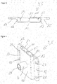
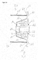
- the Figure 1 shows a first embodiment of a flange plate 3 for a bumper arrangement according to the invention.
- the crash box flange plate 3 is designed as a hollow chamber profile 5 and has a rear wall 11, a front wall 10 and two side walls 12 and 13 connecting the rear wall 11 and the front wall 10.
- the rear wall 11 also has webs 17 and 18 protruding beyond the side walls 12 and 13, in which assembly openings 20 are arranged, with the help of which the crash box flange plate 3 is detachably arranged on a body of a motor vehicle, in particular a longitudinal member of a motor vehicle body, for example by means of screw connections can be.
- the hollow chamber profile 5 of the crash box flange plate 3 is in the present case designed as a four-chamber hollow profile, with four hollow chambers being formed between the rear wall 11 and the front wall 10, which are separated from one another by the inner walls 14, 15 and 16 connecting the front wall 10 and the rear wall 11.
- the outer hollow chambers are still delimited by the side walls 12 and 13.
- the crash box flange plate 3 has an opening 9 which extends from the front side 10 through the hollow chamber profile 5 of the crash box flange plate 3 to the rear wall 11 of the crash box flange plate 3.
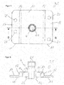
- FIG 2 is the crash box flange plate of the Figure 1 shown in a plan view of the front wall 10 and the surfaces of the webs 17 and 18 of the rear wall 11 facing the front wall 10.
- the side walls 12 and 13 connecting the rear wall 11 and front wall 10 are chamfered and are therefore not at a right angle to the rear wall 11 and the front wall 10 of the crash box flange plate 3, as is also the case in particular in the cross-sectional view through the hollow chamber profile 5 of the crash box flange plate 3 as in Figure 3 is shown.
- the inner walls 14, 15 and 16 are perpendicular to the rear wall 11 and the front wall 10 and connect them to one another.
- the opening 9 extends from the front wall 10 through the entire hollow chamber profile 5 of the crash box flange plate 3 to the rear wall 11.
- the Figures 4 to 6 show the Figures 1 to 3 corresponding representations of the crash box flange plate 3 of Figures 1 to 3 , but here a receptacle 4 for the detachable arrangement of a towing device is pushed through the openings 9.
- the Figure 6 shows a cross-sectional view along the plane BB of Figure 5 . Since the openings 9 are arranged centrally in the center of the crash box flange plate 3, the receptacle 4 for the detachable arrangement of a towing device is also arranged centrally in the crash box flange plate.
- the receptacle 4 has an internal thread 21 in which a corresponding external thread of a towing device, for example a towing eye, can engage.
- the receptacle 4 is designed as a threaded sleeve with an internal thread 21. It can be clearly seen in particular in the Figure 6 that the receptacle 4 has a collar 22 with which, after being pushed through the opening 9 in the crash box flange plate 3, it rests against its rear wall 11 or is supported thereon.
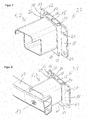
- FIG. 3 is now a perspective view of the crash box flange plate 3 of FIG Figures 1 to 6 shown, with a crash box designed as a single-chamber hollow profile 6 being joined on the front wall 10 of the crash box flange plate 3.
- the joining is advantageously carried out by means of welding, since both the crash box 2 and the Crashbox flange plate 3 are made from a weldable metal.
- both the crash box 2 and the crash box flange 3 can be designed as an extrusion profile.
- the welded connection can take place over the entire circumference of the crash box 2. Alternatively, it is of course also possible for the joining by means of welding to take place only in sections or at points.
- FIG 8 the arrangement of the crash box 2 on the flange plate 3 is now shown in a perspective view, with a cross member 1 now being arranged on the end of the crash box 2 opposite the crash box flange plate 3.
- the cross member 1 has an opening 19 which is arranged in the cross member 1 in such a way that a towing device, in particular a towing eye, can be pushed through this opening 19 and brought into engagement with the receptacle 4.
- the connection between crash box 2 and cross member 1 can also be made by joining by means of a welding process.
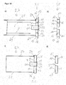
- a crash box flange plate 3 designed as a hollow chamber profile 5 is shown schematically in a cross-sectional view and view from above, the crash box flange plate 3 also again having a front wall 10, a rear wall 11 and side walls 12 and 13 connecting them.
- inside walls 14, 15 and 16 are arranged within the hollow chamber profile 5 of the crash box flange plate 3, which also connect the front wall 10 to the rear wall 11.
- webs 17 and 18 of the rear wall 11 point beyond the side walls 12.
- the illustration clearly shows the Figure 9b also the opening 9 within the crash box flange plate 3.
- both a crash box 2, which in the present case is designed as a single-chamber hollow profile 6, and a receptacle 4 with an internal thread 21 for detachable arrangement of a towing device are arranged on the crash box flange plate 3.
- the crash box 2 with side walls 25 and 26 protrudes beyond the front wall 10 of the crash box flange plate 3 to its rear wall 11 and is supported with the side wall 26 on the side wall 12 of the crash box flange plate 3 and with the side wall 25 on the side wall 13 of the crash box flange plate 3 from.
- the crash box 6 is joined to the crash box flange plate 3 by means of a welded connection 24.
- the receptacle 4 pushed through the opening 9 has a circumferential collar 22 which is supported on the rear wall 11 of the crash box flange plate 3 and is joined to the latter by means of a welded connection 23.
- the receptacle 4 is also joined to the front wall 10 by means of a welded connection 23.
- FIG. 9d now shows a cross-sectional view of the crash box flange plate 3 of FIG Figure 9b in a corresponding view from the side.
- FIG. 9c a corresponding side view in cross section through the inner wall 15 is shown, in which a crash box 2 is already arranged on the crash box flange plate 3.
- the crash box flange plate 3 is joined to the upper wall 27 and to the lower wall 28 of the crash box 2 by means of a welded connection 24.
- the welded connection 24 can run around the entire crash box 2. Alternatively, it can of course also be the case that the welded connection 24 is formed only in sections or at certain points.
- FIG 10 shows an embodiment of a crash box flange plate 3 on which a crash box 2 is arranged.
- the crash box 2 is again designed as a single-chamber hollow profile 6, while the crash box flange plate 3 is designed as a multi-chamber hollow profile with four hollow chambers.
- the hollow chambers are again formed by the front wall 10, the rear wall 11 and the side walls 12 and 13 and the inner walls 14, 15 and 16.
- the rear wall 11 also has webs 17 and 18 protruding beyond the side walls 12 and 13, in which mounting openings 20 are arranged for the particularly detachable arrangement of the crash box flange plate 3 on a motor vehicle body, in particular a longitudinal member of a motor vehicle body.
- the side walls 12 and 13 are formed perpendicular to the front wall 10 and the rear wall 11.
- the crash box 2 is supported on these side walls 12 and 13 with side walls 25 and 26, the side walls 25 and 26 extending to the rear wall 11 or the webs 17 and 18 of the rear wall 11.
- the upper wall 27 and the lower wall 28, not shown here, of the crash box 2 only extend as far as the front wall 10.
- crash box 2 can now again be joined to the crash box flange plate 3 by means of a welded connection (not shown here), this welded connection again being able to encompass the entire crash box.
- a welded connection (not shown here)
- this welded connection again being able to encompass the entire crash box.
- FIG 11b is a crash box flange plate 3 corresponding to the crash box flange plate of Figure 5b shown in a cross-sectional view.
- the crash box flange plate 3 of the Figure 11b corresponds to that of Figure 9b .
- the crash box flange plate 3 of Figure 11b is now again the crash box flange plate 3 of Figure 11b shown, with a crash box 2 already being arranged on the crash box flange plate 3 or being joined to it.
- the crash box flange plate 3 which is also designed as a single-chamber hollow profile 6, is now joined to the crash box flange plate 3 in the area of the front wall 10.
- the welded connection 24 can in turn be designed to run around the entire crash box 2 via the side walls 25 and 26 as well as the upper wall 27 and the lower wall 28. However, it is also possible here to form the welded connection 24 only in sections or at certain points.
- the receptacle 4 is pushed through the opening 9 of the crash box flange plate 3 and is supported with a circumferential collar 22 on the rear side 11 of the crash box flange plate 3. In the area of the circumferential collar 22, the receptacle 4 is joined to the crash box flange plate 3 on its rear side 11 by means of a welded connection 23.
- the receptacle 4 has an internal thread 21 which corresponds to a corresponding external thread of a towing device, in particular a towing eye.
- FIG. 11d is a cross-sectional representation in a side view through the inner wall 15 of the crash box flange plate 3 is shown.
- FIG. 12 a further exemplary embodiment of a crash box flange plate 3 for a bumper arrangement according to the invention is shown, to which a crash box 2 is arranged.
- the crash box 2 is again designed as a single-chamber hollow profile 6 and has two side walls 25 and 26 which extend up to a front wall 10 of the crash box flange plate 3 and are joined to the crash box flange plate 3 there via a welded connection 24.
- the crash box flange plate 3 is again designed here as a multi-chamber hollow profile, the individual hollow chambers in turn being formed by the front wall 10 and the rear wall 11 and the side walls 12 and 13 and inner walls 14 and 16 connecting them.
- a receptacle 4 for the detachable arrangement of a towing device, in particular a towing eye, is already inserted through the opening 9 within the crash box flange plate 3.
- the receptacle 4 is supported with a circumferential collar 22 on the rear wall 11 of the crash box flange plate 3 and is also joined to it there.
- the latter has an internal thread 21 which corresponds to an external thread of a towing device, in particular a towing eye.
- the rear wall 11 of the crash box flange plate 3 also in this exemplary embodiment has webs 17 and 18 protruding beyond the side walls 12 and 13, which, for example, have assembly openings for the particularly detachable arrangement of the crash box flange plate 3 on a motor vehicle body, in particular a longitudinal member of a motor vehicle body.
- the Figure 13b now shows a crash box flange plate 3 in a cross-sectional view in a view from above, the hollow chamber profile 5 of the crash box flange plate 3 being formed by the front wall 10 and the rear wall 11 and side walls 12 and 13 connecting them.
- FIG 13a shows a cross-sectional view of the crash box flange plate of FIG Figure 13b , where a crash box 2 is already arranged on the crash box flange plate 3. It can be clearly seen here that the hollow chamber profile 5 of the crash box flange plate 3 now lies entirely within the single-chamber hollow profile 6 of the crash box 2.
- the crash box 2 extends with its side walls 25 and 26 as far as the webs 17 and 18 of the rear wall 11 of the crash box flange plate 3 and is joined there to the crash box flange plate 3 by means of a welded connection 24.
- the side walls 25 and 26 of the crash box 2 are spaced apart from the side walls 12 and 13 of the crash box flange plate 3.
- the arrangement in the receptacle 4 with internal thread 21 within the opening 9 of the crash box flange plate 3 corresponds essentially to that of the exemplary embodiments described above.
- FIG 14 a further embodiment of a crash box flange plate 3 is shown in a cross-sectional view, on which a crash box 2 is already arranged.
- the crash box flange plate 3 is designed as a multi-chamber hollow profile 5, the hollow chambers being formed by the side walls 12 and 13, the front wall 10 and 11 and the parallel inner wall 15 'and the perpendicular inner walls 14, 14' and 16 and 16 '.
- the side walls 25 and 26 of the crash box 2 are spaced apart from the side walls 12 and 13 of the crash box flange plate 3.
- the side walls 12 and 13 of the crash box flange plate 3 are again at an angle other than 90 ° on the rear wall 11 and the front wall 10 of the crash box flange plate.
- the connection of the crash box flange plate 3 to the crash box 2 takes place here again by joining by means of a welding process with the formation of a welded connection 24.
- the receptacle 4 is in the present case again formed with a collar 22, which is supported on the rear wall 11 of the crash box flange plate 3 and there with this is joined by means of a welded connection 23.
- This receptacle 4 again has an internal thread 21 which corresponds to a corresponding external thread of a towing eye.
- the opening 9 for inserting the receptacle 4 is arranged centrally within the crash box flange plate 3, in the exemplary embodiment the Figures 15a to 15d a crash box flange plate is now shown which has an opening 9 outside the center of the crash box flange plate 3.
- the crash box flange plate 3 is again designed as a multi-chamber hollow profile 5, as in particular in the cross-sectional view of FIG Figure 15b can be seen.
- the multiple hollow chambers are again formed by the front wall 10, the rear wall 11 and the side walls 12 and 13 connecting them and the inner walls 14 and 16.
- the crash box flange plate 3 with a crash box 2 joined, the crash box 2 being designed as a multi-chamber hollow profile 7.
- the crash box 2 has an inner wall 8 cut out locally in the region of the receptacle 4.
- the side walls 25 and 26 are again joined to the crash box flange plate 3 in the area of the front wall 10 by means of a welded connection 24.
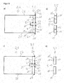
- FIGS. 16a to 16d now show an embodiment which is essentially that of Figures 11a to 11d corresponds, although the crash box flange plate 3 is not connected here to a crash box 2 designed as a single-chamber hollow profile. Rather, the crash box 2 is designed as a multi-chamber hollow profile in this exemplary embodiment. Inside the crash box 2, inner walls 8 are arranged through which the several chambers of the multi-chamber hollow profile 7 are formed.
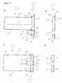
- FIGS. 17a to 17d now show, in contrast to the previously described exemplary embodiments in which the receptacle 4 was arranged inside a hollow chamber of the crash box 2, an exemplary embodiment in which the receptacle 4 is arranged outside the crash box 2.
- FIG. 7b a cross-sectional view of a crash box flange plate 3 is shown, which corresponds to a side view.
- the crash box flange plate 3 is designed as a single-chamber hollow profile and has a front wall 10, a rear wall 11 and an upper side wall 12 and a lower side wall 13, the two side walls 12 and 13 connecting the front wall 10 and rear wall 11 to one another and standing perpendicular to them.
- the rear wall 11 has webs 17 and 18 beyond the side walls 12.
- Inside the crash box flange plate 3 there is again an opening 9 for a receptacle 4 for the detachable arrangement of a towing device, in particular a towing eye.
- the opening 9 is not located centrally in the crash box flange plate 3, but is arranged in the lower half of the crash box flange plate 3.
- FIG. 17a is now on the crash box flange plate 3 both a crash box 2, which In the present case, a multi-chamber hollow profile 7 with two hollow chambers separated by an inner wall 8 is formed, and a receptacle 4 with an internal thread 21 is arranged for the detachable arrangement of a towing device.
- the crash box 2 with its upper wall 25 and lower wall 26 is joined to the front wall 10 of the crash box flange plate 3 by means of welded connections 24.
- the receptacle 4 pushed through the opening 9 has a circumferential collar 22 which is supported on the rear wall 11 of the crash box flange plate 3 and is joined to the latter by means of a welded connection 23.
- the receptacle 4 can also be joined to the front wall 10 by means of a welded connection 23, but this is not shown here.
- the receptacle 4 is arranged outside the crash box 2, so that a cross member arranged on the crash box 2 does not have to have an opening for inserting a towing device. Rather, it can be guided past the cross member below and connected to the receptacle 4.
- Figure 17c can be seen, which shows a plan view from below of the crash box flange plate 3 with the crash box 2 arranged thereon.
- the top view of the lower wall 28 of the crash box 2 clearly shows that the receptacle 4 is arranged outside the crash box 2.
- Figure 17d shows the crash box flange plate 3 without a receptacle 4 and without a crash box 2 arranged thereon.
Landscapes
- Engineering & Computer Science (AREA)
- Mechanical Engineering (AREA)
- Transportation (AREA)
- Body Structure For Vehicles (AREA)
Claims (17)
- Système de pare-chocs pour un véhicule automobile, comprenant une traverse (1) à laquelle sont accouplées des crashbox (2), des plaques à bride de crashbox (3) étant disposées au niveau des crashbox (2) à l'opposé de la traverse (1) pour fixer les crashbox (2) à une carrosserie ou à un châssis d'un véhicule automobile, un logement (4) s'étendant dans la direction de la traverse (1) étant disposé par engagement par force, par correspondance de formes et/ou par liaison de matière au niveau d'au moins une plaque à bride de crashbox (3), le logement (4) étant réalisé pour l'agencement amovible d'un dispositif de remorquage, caractérisé en ce que l'au moins une plaque à bride de crashbox (3) est réalisée sous forme de profilé à chambre creuse (5).
- Système de pare-chocs selon la revendication 1, caractérisé en ce que l'au moins une plaque à bride de crashbox (3) est réalisée sous forme de profilé creux à une seule chambre.
- Système de pare-chocs selon la revendication 1, caractérisé en ce que l'au moins une plaque à bride de crashbox (3) est réalisée sous forme de profilé creux à plusieurs chambres.
- Système de pare-chocs selon l'une quelconque des revendications précédentes, caractérisé en ce que la plaque à bride de crashbox (3) présente une paroi avant (10), une paroi arrière (11) ainsi que deux parois latérales (12, 13) reliant la paroi avant (10) et la paroi arrière (11).
- Système de pare-chocs selon l'une quelconque des revendications 3 et 4, caractérisé en ce que la plaque à bride de crashbox (3) présente au moins une paroi intérieure (14, 15, 16) reliant la paroi avant (10) et la paroi arrière (11).
- Système de pare-chocs selon l'une quelconque des revendications 4 à 6, caractérisé en ce que la paroi arrière (11) présentent des nervures (17, 18) qui font saillie au-delà des parois latérales (12, 13).
- Système de pare-chocs selon l'une quelconque des revendications 4 à 6, caractérisé en ce que sur la paroi avant (10) de l'au moins une plaque à bride de crashbox (3) est assemblée une crashbox (2).
- Système de pare-chocs selon l'une quelconque des revendications 4 à 6, caractérisé en ce que sur la paroi arrière (11) de la plaque à bride de crashbox (3) est assemblée une crashbox (2).
- Système de pare-chocs selon la revendication 8, caractérisé en ce que la crashbox (2) s'appuie ou s'applique contre au moins l'une des parois latérales (12, 13).
- Système de pare-chocs selon l'une quelconque des revendications précédentes, caractérisé en ce que l'au moins une plaque à bride de crashbox (3) est réalisée sous forme de profilé extrudé.
- Système de pare-chocs selon l'une quelconque des revendications précédentes, caractérisé en ce que les crashbox (2) sont réalisées sous forme de profilé creux à une seule chambre (6).
- Système de pare-chocs selon l'une quelconque des revendications 1 à 4, caractérisé en ce que les crashbox (2) sont réalisées sous forme de profilé à plusieurs chambres (7).
- Système de pare-chocs selon l'une quelconque des revendications précédentes, caractérisé en ce qu'à l'intérieur de l'au moins une plaque à bride de crashbox (3) est prévue une ouverture traversante (8) dans laquelle est enfoncé le logement (4) pour l'agencement amovible d'un dispositif de remorquage.
- Système de pare-chocs selon l'une quelconque des revendications précédentes, caractérisé en ce que le logement (4) est assemblé à la plaque à bride de crashbox (3) au niveau de laquelle il est disposé, le logement étant notamment soudé à la paroi arrière (11) et/ou à la paroi avant (10) de la plaque à bride de crashbox (3).
- Système de pare-chocs selon l'une quelconque des revendications précédentes, caractérisé en ce que la traverse (1) présente une ouverture traversante (19) au moyen de laquelle le logement (4) est réalisé de manière accessible pour un dispositif de remorquage amovible.
- Système de pare-chocs selon l'une quelconque des revendications précédentes, caractérisé en ce que les parois intérieures (14, 15, 16) reliant la paroi arrière (11) et la paroi avant (10) de la plaque à bride de crashbox (3) sont réalisées de manière à s'étendre en diagonale à l'intérieur du profilé à chambre creuse et éventuellement de manière à se croiser.
- Système de pare-chocs selon l'une quelconque des revendications précédentes, caractérisé en ce que le logement (4) est disposé à l'intérieur ou à l'extérieur de la crashbox.
Applications Claiming Priority (1)
| Application Number | Priority Date | Filing Date | Title |
|---|---|---|---|
| DE102018107487.5A DE102018107487A1 (de) | 2018-03-28 | 2018-03-28 | Stoßfängeranordnung für ein Kraftfahrzeug |
Publications (2)
| Publication Number | Publication Date |
|---|---|
| EP3546324A1 EP3546324A1 (fr) | 2019-10-02 |
| EP3546324B1 true EP3546324B1 (fr) | 2021-01-27 |
Family
ID=65729169
Family Applications (1)
| Application Number | Title | Priority Date | Filing Date |
|---|---|---|---|
| EP19161531.9A Active EP3546324B1 (fr) | 2018-03-28 | 2019-03-08 | Dispositif pare-chocs pour un véhicule automobile |
Country Status (3)
| Country | Link |
|---|---|
| EP (1) | EP3546324B1 (fr) |
| CN (1) | CN110316126B (fr) |
| DE (1) | DE102018107487A1 (fr) |
Families Citing this family (3)
| Publication number | Priority date | Publication date | Assignee | Title |
|---|---|---|---|---|
| DE102020114662A1 (de) * | 2020-06-02 | 2021-12-02 | Benteler Automobiltechnik Gmbh | Querträger für ein Stoßfängersystem eines Kraftfahrzeugs sowie Verfahren zur Herstellung eines solchen Querträgers |
| DE102020122965A1 (de) * | 2020-09-02 | 2022-03-03 | ACPS Automotive GmbH | Montagesystem |
| CN113650576A (zh) * | 2021-08-02 | 2021-11-16 | 合肥工业大学 | 一种复式吸能盒及具有该吸能盒的汽车 |
Family Cites Families (9)
| Publication number | Priority date | Publication date | Assignee | Title |
|---|---|---|---|---|
| EP1721786B1 (fr) | 2005-05-13 | 2012-03-28 | Constellium Switzerland AG | Système de pare-chocs |
| JP4737768B2 (ja) * | 2006-08-04 | 2011-08-03 | 株式会社神戸製鋼所 | 脱着式牽引フックの取付構造 |
| DE102007060113A1 (de) * | 2007-12-13 | 2009-06-18 | Benteler Automobiltechnik Gmbh | Verfahren zur Herstellung eines Stoßfängers und Stoßfänger |
| DE102010006975A1 (de) * | 2010-02-05 | 2011-08-11 | GM Global Technology Operations LLC, ( n. d. Ges. d. Staates Delaware ), Mich. | Kraftfahrzeug-Vorderbau |
| JP5634896B2 (ja) * | 2011-01-26 | 2014-12-03 | 昭和電工株式会社 | 車両用衝撃吸収部材 |
| DE102011010798A1 (de) | 2011-02-09 | 2012-08-09 | Benteler Automobiltechnik Gmbh | Stoßfängeranordnung mit Abschleppvorrichtung |
| JP2012224099A (ja) * | 2011-04-14 | 2012-11-15 | Toyoda Iron Works Co Ltd | 車両のフック取付構造およびフック取付モジュール |
| CN205524081U (zh) * | 2016-01-26 | 2016-08-31 | 北京长城华冠汽车科技股份有限公司 | 一种吸能盒和包括该吸能盒的汽车 |
| CN106043183A (zh) * | 2016-07-29 | 2016-10-26 | 奇瑞新能源汽车技术有限公司 | 汽车前防撞梁总成 |
-
2018
- 2018-03-28 DE DE102018107487.5A patent/DE102018107487A1/de not_active Withdrawn
-
2019
- 2019-03-08 EP EP19161531.9A patent/EP3546324B1/fr active Active
- 2019-03-28 CN CN201910241940.2A patent/CN110316126B/zh active Active
Non-Patent Citations (1)
| Title |
|---|
| None * |
Also Published As
| Publication number | Publication date |
|---|---|
| CN110316126B (zh) | 2022-12-02 |
| CN110316126A (zh) | 2019-10-11 |
| EP3546324A1 (fr) | 2019-10-02 |
| DE102018107487A1 (de) | 2019-10-02 |
Similar Documents
| Publication | Publication Date | Title |
|---|---|---|
| DE102007035483B4 (de) | Crasheinrichtung | |
| EP1837245B1 (fr) | Ensemble pare-chocs | |
| EP1669248B1 (fr) | Agencement de pare-choc pour un véhicule automobile | |
| EP1625978A1 (fr) | Absorbeur de choc | |
| DE102011117933A1 (de) | Crashbox | |
| DE10321573B4 (de) | Crashstruktur für eine Kraftwagen-Rohbaustruktur | |
| EP3546324B1 (fr) | Dispositif pare-chocs pour un véhicule automobile | |
| WO2019025176A1 (fr) | Profilé de chambre creuse servant à la fixation d'un module de batterie | |
| EP2508407A1 (fr) | Structure, en particulier pour les installations électriques dans un véhicule sur rail, et procédé de fabrication de cette structure | |
| EP2698295B1 (fr) | Tube télescopique réglable en longueur, béquille télescopique et procédé de montage | |
| DE102013114789B4 (de) | Verfahren zur Herstellung von Hohlprofilen sowie Hohlprofil | |
| EP2374666A2 (fr) | Agencement de liaison d'au moins deux composants structurels pour un véhicule automobile et son procédé de fabrication | |
| DE102014018755B3 (de) | Fahrzeugkarosserie | |
| EP3715184B1 (fr) | Agencement de pare-chocs | |
| EP1710149B2 (fr) | Traverse terminale pour véhicule utilitaire | |
| DE102014101757B4 (de) | Hohlprofilbauteil mit Flansch | |
| DE102018106224B4 (de) | Stoßfängeranordnung für ein Kraftfahrzeug | |
| DE202011108692U1 (de) | Hohlprofil und Hallengerüst mit einem solchen Profil | |
| DE102020132481B4 (de) | Energieabsorptionsvorrichtung für eine Stoßfängeranordnung eines Kraftfahrzeuges sowie Stoßfängeranordnung eines Kraftfahrzeuges | |
| DE10058998C1 (de) | Stoßfängereinheit eines Kraftfahrzeuges | |
| EP4412888B1 (fr) | Ensemble de répartition de charge dans un véhicule | |
| DE10036790B4 (de) | Befestigungsanordnung zum Fügen von benachbarten Leichtbauplatten einer Fahrzeugtragstruktur | |
| BE1031413B1 (de) | Gleitelement für eine Lenksäule eines Kraftfahrzeugs und Lenksäule für ein Kraftfahrzeug | |
| DE102015014484B4 (de) | Strebenelement für einen Frontendträger eines Kraftwagens | |
| EP1743863A1 (fr) | Elément de connexion |
Legal Events
| Date | Code | Title | Description |
|---|---|---|---|
| PUAI | Public reference made under article 153(3) epc to a published international application that has entered the european phase |
Free format text: ORIGINAL CODE: 0009012 |
|
| STAA | Information on the status of an ep patent application or granted ep patent |
Free format text: STATUS: THE APPLICATION HAS BEEN PUBLISHED |
|
| AK | Designated contracting states |
Kind code of ref document: A1 Designated state(s): AL AT BE BG CH CY CZ DE DK EE ES FI FR GB GR HR HU IE IS IT LI LT LU LV MC MK MT NL NO PL PT RO RS SE SI SK SM TR |
|
| AX | Request for extension of the european patent |
Extension state: BA ME |
|
| STAA | Information on the status of an ep patent application or granted ep patent |
Free format text: STATUS: REQUEST FOR EXAMINATION WAS MADE |
|
| 17P | Request for examination filed |
Effective date: 20200402 |
|
| RBV | Designated contracting states (corrected) |
Designated state(s): AL AT BE BG CH CY CZ DE DK EE ES FI FR GB GR HR HU IE IS IT LI LT LU LV MC MK MT NL NO PL PT RO RS SE SI SK SM TR |
|
| GRAP | Despatch of communication of intention to grant a patent |
Free format text: ORIGINAL CODE: EPIDOSNIGR1 |
|
| STAA | Information on the status of an ep patent application or granted ep patent |
Free format text: STATUS: GRANT OF PATENT IS INTENDED |
|
| INTG | Intention to grant announced |
Effective date: 20200818 |
|
| GRAS | Grant fee paid |
Free format text: ORIGINAL CODE: EPIDOSNIGR3 |
|
| GRAA | (expected) grant |
Free format text: ORIGINAL CODE: 0009210 |
|
| STAA | Information on the status of an ep patent application or granted ep patent |
Free format text: STATUS: THE PATENT HAS BEEN GRANTED |
|
| AK | Designated contracting states |
Kind code of ref document: B1 Designated state(s): AL AT BE BG CH CY CZ DE DK EE ES FI FR GB GR HR HU IE IS IT LI LT LU LV MC MK MT NL NO PL PT RO RS SE SI SK SM TR |
|
| REG | Reference to a national code |
Ref country code: GB Ref legal event code: FG4D Free format text: NOT ENGLISH |
|
| REG | Reference to a national code |
Ref country code: CH Ref legal event code: EP |
|
| REG | Reference to a national code |
Ref country code: AT Ref legal event code: REF Ref document number: 1358104 Country of ref document: AT Kind code of ref document: T Effective date: 20210215 |
|
| REG | Reference to a national code |
Ref country code: IE Ref legal event code: FG4D Free format text: LANGUAGE OF EP DOCUMENT: GERMAN |
|
| REG | Reference to a national code |
Ref country code: DE Ref legal event code: R096 Ref document number: 502019000752 Country of ref document: DE |
|
| REG | Reference to a national code |
Ref country code: NL Ref legal event code: MP Effective date: 20210127 |
|
| REG | Reference to a national code |
Ref country code: LT Ref legal event code: MG9D |
|
| PG25 | Lapsed in a contracting state [announced via postgrant information from national office to epo] |
Ref country code: BG Free format text: LAPSE BECAUSE OF FAILURE TO SUBMIT A TRANSLATION OF THE DESCRIPTION OR TO PAY THE FEE WITHIN THE PRESCRIBED TIME-LIMIT Effective date: 20210427 Ref country code: HR Free format text: LAPSE BECAUSE OF FAILURE TO SUBMIT A TRANSLATION OF THE DESCRIPTION OR TO PAY THE FEE WITHIN THE PRESCRIBED TIME-LIMIT Effective date: 20210127 Ref country code: GR Free format text: LAPSE BECAUSE OF FAILURE TO SUBMIT A TRANSLATION OF THE DESCRIPTION OR TO PAY THE FEE WITHIN THE PRESCRIBED TIME-LIMIT Effective date: 20210428 Ref country code: FI Free format text: LAPSE BECAUSE OF FAILURE TO SUBMIT A TRANSLATION OF THE DESCRIPTION OR TO PAY THE FEE WITHIN THE PRESCRIBED TIME-LIMIT Effective date: 20210127 Ref country code: LT Free format text: LAPSE BECAUSE OF FAILURE TO SUBMIT A TRANSLATION OF THE DESCRIPTION OR TO PAY THE FEE WITHIN THE PRESCRIBED TIME-LIMIT Effective date: 20210127 Ref country code: NO Free format text: LAPSE BECAUSE OF FAILURE TO SUBMIT A TRANSLATION OF THE DESCRIPTION OR TO PAY THE FEE WITHIN THE PRESCRIBED TIME-LIMIT Effective date: 20210427 Ref country code: PT Free format text: LAPSE BECAUSE OF FAILURE TO SUBMIT A TRANSLATION OF THE DESCRIPTION OR TO PAY THE FEE WITHIN THE PRESCRIBED TIME-LIMIT Effective date: 20210527 |
|
| PG25 | Lapsed in a contracting state [announced via postgrant information from national office to epo] |
Ref country code: RS Free format text: LAPSE BECAUSE OF FAILURE TO SUBMIT A TRANSLATION OF THE DESCRIPTION OR TO PAY THE FEE WITHIN THE PRESCRIBED TIME-LIMIT Effective date: 20210127 Ref country code: PL Free format text: LAPSE BECAUSE OF FAILURE TO SUBMIT A TRANSLATION OF THE DESCRIPTION OR TO PAY THE FEE WITHIN THE PRESCRIBED TIME-LIMIT Effective date: 20210127 Ref country code: LV Free format text: LAPSE BECAUSE OF FAILURE TO SUBMIT A TRANSLATION OF THE DESCRIPTION OR TO PAY THE FEE WITHIN THE PRESCRIBED TIME-LIMIT Effective date: 20210127 Ref country code: SE Free format text: LAPSE BECAUSE OF FAILURE TO SUBMIT A TRANSLATION OF THE DESCRIPTION OR TO PAY THE FEE WITHIN THE PRESCRIBED TIME-LIMIT Effective date: 20210127 |
|
| PG25 | Lapsed in a contracting state [announced via postgrant information from national office to epo] |
Ref country code: IS Free format text: LAPSE BECAUSE OF FAILURE TO SUBMIT A TRANSLATION OF THE DESCRIPTION OR TO PAY THE FEE WITHIN THE PRESCRIBED TIME-LIMIT Effective date: 20210527 |
|
| REG | Reference to a national code |
Ref country code: DE Ref legal event code: R097 Ref document number: 502019000752 Country of ref document: DE |
|
| PG25 | Lapsed in a contracting state [announced via postgrant information from national office to epo] |
Ref country code: SM Free format text: LAPSE BECAUSE OF FAILURE TO SUBMIT A TRANSLATION OF THE DESCRIPTION OR TO PAY THE FEE WITHIN THE PRESCRIBED TIME-LIMIT Effective date: 20210127 Ref country code: EE Free format text: LAPSE BECAUSE OF FAILURE TO SUBMIT A TRANSLATION OF THE DESCRIPTION OR TO PAY THE FEE WITHIN THE PRESCRIBED TIME-LIMIT Effective date: 20210127 Ref country code: CZ Free format text: LAPSE BECAUSE OF FAILURE TO SUBMIT A TRANSLATION OF THE DESCRIPTION OR TO PAY THE FEE WITHIN THE PRESCRIBED TIME-LIMIT Effective date: 20210127 Ref country code: MC Free format text: LAPSE BECAUSE OF FAILURE TO SUBMIT A TRANSLATION OF THE DESCRIPTION OR TO PAY THE FEE WITHIN THE PRESCRIBED TIME-LIMIT Effective date: 20210127 |
|
| PG25 | Lapsed in a contracting state [announced via postgrant information from national office to epo] |
Ref country code: DK Free format text: LAPSE BECAUSE OF FAILURE TO SUBMIT A TRANSLATION OF THE DESCRIPTION OR TO PAY THE FEE WITHIN THE PRESCRIBED TIME-LIMIT Effective date: 20210127 Ref country code: RO Free format text: LAPSE BECAUSE OF FAILURE TO SUBMIT A TRANSLATION OF THE DESCRIPTION OR TO PAY THE FEE WITHIN THE PRESCRIBED TIME-LIMIT Effective date: 20210127 Ref country code: SK Free format text: LAPSE BECAUSE OF FAILURE TO SUBMIT A TRANSLATION OF THE DESCRIPTION OR TO PAY THE FEE WITHIN THE PRESCRIBED TIME-LIMIT Effective date: 20210127 |
|
| PLBE | No opposition filed within time limit |
Free format text: ORIGINAL CODE: 0009261 |
|
| STAA | Information on the status of an ep patent application or granted ep patent |
Free format text: STATUS: NO OPPOSITION FILED WITHIN TIME LIMIT |
|
| REG | Reference to a national code |
Ref country code: BE Ref legal event code: MM Effective date: 20210331 |
|
| 26N | No opposition filed |
Effective date: 20211028 |
|
| PG25 | Lapsed in a contracting state [announced via postgrant information from national office to epo] |
Ref country code: ES Free format text: LAPSE BECAUSE OF FAILURE TO SUBMIT A TRANSLATION OF THE DESCRIPTION OR TO PAY THE FEE WITHIN THE PRESCRIBED TIME-LIMIT Effective date: 20210127 Ref country code: AL Free format text: LAPSE BECAUSE OF FAILURE TO SUBMIT A TRANSLATION OF THE DESCRIPTION OR TO PAY THE FEE WITHIN THE PRESCRIBED TIME-LIMIT Effective date: 20210127 Ref country code: IE Free format text: LAPSE BECAUSE OF NON-PAYMENT OF DUE FEES Effective date: 20210308 Ref country code: LU Free format text: LAPSE BECAUSE OF NON-PAYMENT OF DUE FEES Effective date: 20210308 |
|
| PG25 | Lapsed in a contracting state [announced via postgrant information from national office to epo] |
Ref country code: SI Free format text: LAPSE BECAUSE OF FAILURE TO SUBMIT A TRANSLATION OF THE DESCRIPTION OR TO PAY THE FEE WITHIN THE PRESCRIBED TIME-LIMIT Effective date: 20210127 |
|
| PG25 | Lapsed in a contracting state [announced via postgrant information from national office to epo] |
Ref country code: IT Free format text: LAPSE BECAUSE OF FAILURE TO SUBMIT A TRANSLATION OF THE DESCRIPTION OR TO PAY THE FEE WITHIN THE PRESCRIBED TIME-LIMIT Effective date: 20210127 |
|
| PG25 | Lapsed in a contracting state [announced via postgrant information from national office to epo] |
Ref country code: IS Free format text: LAPSE BECAUSE OF FAILURE TO SUBMIT A TRANSLATION OF THE DESCRIPTION OR TO PAY THE FEE WITHIN THE PRESCRIBED TIME-LIMIT Effective date: 20210527 |
|
| PG25 | Lapsed in a contracting state [announced via postgrant information from national office to epo] |
Ref country code: BE Free format text: LAPSE BECAUSE OF NON-PAYMENT OF DUE FEES Effective date: 20210331 |
|
| REG | Reference to a national code |
Ref country code: CH Ref legal event code: PL |
|
| REG | Reference to a national code |
Ref country code: DE Ref legal event code: R082 Ref document number: 502019000752 Country of ref document: DE Representative=s name: SPRENGER, GERRIT, DIPL.-PHYS. DR.RER.NAT., DE Ref country code: DE Ref legal event code: R082 Ref document number: 502019000752 Country of ref document: DE Representative=s name: BOCKERMANN KSOLL GRIEPENSTROH OSTERHOFF, DE |
|
| PG25 | Lapsed in a contracting state [announced via postgrant information from national office to epo] |
Ref country code: LI Free format text: LAPSE BECAUSE OF NON-PAYMENT OF DUE FEES Effective date: 20220331 Ref country code: CH Free format text: LAPSE BECAUSE OF NON-PAYMENT OF DUE FEES Effective date: 20220331 |
|
| PG25 | Lapsed in a contracting state [announced via postgrant information from national office to epo] |
Ref country code: NL Free format text: LAPSE BECAUSE OF NON-PAYMENT OF DUE FEES Effective date: 20210127 Ref country code: CY Free format text: LAPSE BECAUSE OF FAILURE TO SUBMIT A TRANSLATION OF THE DESCRIPTION OR TO PAY THE FEE WITHIN THE PRESCRIBED TIME-LIMIT Effective date: 20210127 |
|
| PG25 | Lapsed in a contracting state [announced via postgrant information from national office to epo] |
Ref country code: HU Free format text: LAPSE BECAUSE OF FAILURE TO SUBMIT A TRANSLATION OF THE DESCRIPTION OR TO PAY THE FEE WITHIN THE PRESCRIBED TIME-LIMIT; INVALID AB INITIO Effective date: 20190308 |
|
| GBPC | Gb: european patent ceased through non-payment of renewal fee |
Effective date: 20230308 |
|
| PG25 | Lapsed in a contracting state [announced via postgrant information from national office to epo] |
Ref country code: GB Free format text: LAPSE BECAUSE OF NON-PAYMENT OF DUE FEES Effective date: 20230308 |
|
| PG25 | Lapsed in a contracting state [announced via postgrant information from national office to epo] |
Ref country code: GB Free format text: LAPSE BECAUSE OF NON-PAYMENT OF DUE FEES Effective date: 20230308 |
|
| PG25 | Lapsed in a contracting state [announced via postgrant information from national office to epo] |
Ref country code: MK Free format text: LAPSE BECAUSE OF FAILURE TO SUBMIT A TRANSLATION OF THE DESCRIPTION OR TO PAY THE FEE WITHIN THE PRESCRIBED TIME-LIMIT Effective date: 20210127 |
|
| PG25 | Lapsed in a contracting state [announced via postgrant information from national office to epo] |
Ref country code: TR Free format text: LAPSE BECAUSE OF FAILURE TO SUBMIT A TRANSLATION OF THE DESCRIPTION OR TO PAY THE FEE WITHIN THE PRESCRIBED TIME-LIMIT Effective date: 20210127 |
|
| PG25 | Lapsed in a contracting state [announced via postgrant information from national office to epo] |
Ref country code: MT Free format text: LAPSE BECAUSE OF FAILURE TO SUBMIT A TRANSLATION OF THE DESCRIPTION OR TO PAY THE FEE WITHIN THE PRESCRIBED TIME-LIMIT Effective date: 20210127 |
|
| REG | Reference to a national code |
Ref country code: DE Ref legal event code: R082 Ref document number: 502019000752 Country of ref document: DE Representative=s name: BOCKERMANN KSOLL GRIEPENSTROH OSTERHOFF, DE |
|
| REG | Reference to a national code |
Ref country code: AT Ref legal event code: MM01 Ref document number: 1358104 Country of ref document: AT Kind code of ref document: T Effective date: 20240308 |
|
| PG25 | Lapsed in a contracting state [announced via postgrant information from national office to epo] |
Ref country code: AT Free format text: LAPSE BECAUSE OF NON-PAYMENT OF DUE FEES Effective date: 20240308 |
|
| PGFP | Annual fee paid to national office [announced via postgrant information from national office to epo] |
Ref country code: DE Payment date: 20260327 Year of fee payment: 8 |
|
| PGFP | Annual fee paid to national office [announced via postgrant information from national office to epo] |
Ref country code: AT Payment date: 20260410 Year of fee payment: 5 |
|
| PGFP | Annual fee paid to national office [announced via postgrant information from national office to epo] |
Ref country code: FR Payment date: 20260320 Year of fee payment: 8 |