EP3546366B1 - Propellerantriebseinheit, die einen verbrennungsmotor und einen elektromotor umfasst, sowie eine solche propellerantriebseinheit umfassendes luftfahrzeug - Google Patents
Propellerantriebseinheit, die einen verbrennungsmotor und einen elektromotor umfasst, sowie eine solche propellerantriebseinheit umfassendes luftfahrzeug Download PDFInfo
- Publication number
- EP3546366B1 EP3546366B1 EP19165911.9A EP19165911A EP3546366B1 EP 3546366 B1 EP3546366 B1 EP 3546366B1 EP 19165911 A EP19165911 A EP 19165911A EP 3546366 B1 EP3546366 B1 EP 3546366B1
- Authority
- EP
- European Patent Office
- Prior art keywords
- propeller
- electric motor
- aircraft
- propulsion unit
- electrical energy
- Prior art date
- Legal status (The legal status is an assumption and is not a legal conclusion. Google has not performed a legal analysis and makes no representation as to the accuracy of the status listed.)
- Active
Links
Images


Classifications
-
- B—PERFORMING OPERATIONS; TRANSPORTING
- B64—AIRCRAFT; AVIATION; COSMONAUTICS
- B64D—EQUIPMENT FOR FITTING IN OR TO AIRCRAFT; FLIGHT SUITS; PARACHUTES; ARRANGEMENT OR MOUNTING OF POWER PLANTS OR PROPULSION TRANSMISSIONS IN AIRCRAFT
- B64D27/00—Arrangement or mounting of power plants in aircraft; Aircraft characterised by the type or position of power plants
- B64D27/02—Aircraft characterised by the type or position of power plants
- B64D27/10—Aircraft characterised by the type or position of power plants of gas-turbine type
- B64D27/12—Aircraft characterised by the type or position of power plants of gas-turbine type within, or attached to, wings
-
- B—PERFORMING OPERATIONS; TRANSPORTING
- B64—AIRCRAFT; AVIATION; COSMONAUTICS
- B64D—EQUIPMENT FOR FITTING IN OR TO AIRCRAFT; FLIGHT SUITS; PARACHUTES; ARRANGEMENT OR MOUNTING OF POWER PLANTS OR PROPULSION TRANSMISSIONS IN AIRCRAFT
- B64D27/00—Arrangement or mounting of power plants in aircraft; Aircraft characterised by the type or position of power plants
- B64D27/02—Aircraft characterised by the type or position of power plants
- B64D27/026—Aircraft characterised by the type or position of power plants comprising different types of power plants, e.g. combination of a piston engine and a gas-turbine
-
- B—PERFORMING OPERATIONS; TRANSPORTING
- B64—AIRCRAFT; AVIATION; COSMONAUTICS
- B64D—EQUIPMENT FOR FITTING IN OR TO AIRCRAFT; FLIGHT SUITS; PARACHUTES; ARRANGEMENT OR MOUNTING OF POWER PLANTS OR PROPULSION TRANSMISSIONS IN AIRCRAFT
- B64D27/00—Arrangement or mounting of power plants in aircraft; Aircraft characterised by the type or position of power plants
- B64D27/02—Aircraft characterised by the type or position of power plants
- B64D27/30—Aircraft characterised by electric power plants
- B64D27/31—Aircraft characterised by electric power plants within, or attached to, wings
-
- B—PERFORMING OPERATIONS; TRANSPORTING
- B64—AIRCRAFT; AVIATION; COSMONAUTICS
- B64D—EQUIPMENT FOR FITTING IN OR TO AIRCRAFT; FLIGHT SUITS; PARACHUTES; ARRANGEMENT OR MOUNTING OF POWER PLANTS OR PROPULSION TRANSMISSIONS IN AIRCRAFT
- B64D27/00—Arrangement or mounting of power plants in aircraft; Aircraft characterised by the type or position of power plants
- B64D27/02—Aircraft characterised by the type or position of power plants
- B64D27/30—Aircraft characterised by electric power plants
- B64D27/33—Hybrid electric aircraft
-
- B—PERFORMING OPERATIONS; TRANSPORTING
- B64—AIRCRAFT; AVIATION; COSMONAUTICS
- B64D—EQUIPMENT FOR FITTING IN OR TO AIRCRAFT; FLIGHT SUITS; PARACHUTES; ARRANGEMENT OR MOUNTING OF POWER PLANTS OR PROPULSION TRANSMISSIONS IN AIRCRAFT
- B64D35/00—Transmitting power from power plants to propellers or rotors; Arrangements of transmissions
- B64D35/02—Transmitting power from power plants to propellers or rotors; Arrangements of transmissions specially adapted for specific power plants
- B64D35/021—Transmitting power from power plants to propellers or rotors; Arrangements of transmissions specially adapted for specific power plants for electric power plants
- B64D35/022—Transmitting power from power plants to propellers or rotors; Arrangements of transmissions specially adapted for specific power plants for electric power plants of hybrid-electric type
- B64D35/024—Transmitting power from power plants to propellers or rotors; Arrangements of transmissions specially adapted for specific power plants for electric power plants of hybrid-electric type of series type
-
- B—PERFORMING OPERATIONS; TRANSPORTING
- B64—AIRCRAFT; AVIATION; COSMONAUTICS
- B64D—EQUIPMENT FOR FITTING IN OR TO AIRCRAFT; FLIGHT SUITS; PARACHUTES; ARRANGEMENT OR MOUNTING OF POWER PLANTS OR PROPULSION TRANSMISSIONS IN AIRCRAFT
- B64D35/00—Transmitting power from power plants to propellers or rotors; Arrangements of transmissions
- B64D35/08—Transmitting power from power plants to propellers or rotors; Arrangements of transmissions characterised by the transmission being driven by a plurality of power plants
-
- F—MECHANICAL ENGINEERING; LIGHTING; HEATING; WEAPONS; BLASTING
- F01—MACHINES OR ENGINES IN GENERAL; ENGINE PLANTS IN GENERAL; STEAM ENGINES
- F01D—NON-POSITIVE DISPLACEMENT MACHINES OR ENGINES, e.g. STEAM TURBINES
- F01D15/00—Adaptations of machines or engines for special use; Combinations of engines with devices driven thereby
- F01D15/10—Adaptations for driving, or combinations with, electric generators
-
- F—MECHANICAL ENGINEERING; LIGHTING; HEATING; WEAPONS; BLASTING
- F02—COMBUSTION ENGINES; HOT-GAS OR COMBUSTION-PRODUCT ENGINE PLANTS
- F02C—GAS-TURBINE PLANTS; AIR INTAKES FOR JET-PROPULSION PLANTS; CONTROLLING FUEL SUPPLY IN AIR-BREATHING JET-PROPULSION PLANTS
- F02C6/00—Plural gas-turbine plants; Combinations of gas-turbine plants with other apparatus; Adaptations of gas-turbine plants for special use
-
- F—MECHANICAL ENGINEERING; LIGHTING; HEATING; WEAPONS; BLASTING
- F05—INDEXING SCHEMES RELATING TO ENGINES OR PUMPS IN VARIOUS SUBCLASSES OF CLASSES F01-F04
- F05D—INDEXING SCHEME FOR ASPECTS RELATING TO NON-POSITIVE-DISPLACEMENT MACHINES OR ENGINES, GAS-TURBINES OR JET-PROPULSION PLANTS
- F05D2220/00—Application
- F05D2220/30—Application in turbines
- F05D2220/32—Application in turbines in gas turbines
- F05D2220/323—Application in turbines in gas turbines for aircraft propulsion, e.g. jet engines
-
- F—MECHANICAL ENGINEERING; LIGHTING; HEATING; WEAPONS; BLASTING
- F05—INDEXING SCHEMES RELATING TO ENGINES OR PUMPS IN VARIOUS SUBCLASSES OF CLASSES F01-F04
- F05D—INDEXING SCHEME FOR ASPECTS RELATING TO NON-POSITIVE-DISPLACEMENT MACHINES OR ENGINES, GAS-TURBINES OR JET-PROPULSION PLANTS
- F05D2220/00—Application
- F05D2220/70—Application in combination with
- F05D2220/76—Application in combination with an electrical generator
-
- Y—GENERAL TAGGING OF NEW TECHNOLOGICAL DEVELOPMENTS; GENERAL TAGGING OF CROSS-SECTIONAL TECHNOLOGIES SPANNING OVER SEVERAL SECTIONS OF THE IPC; TECHNICAL SUBJECTS COVERED BY FORMER USPC CROSS-REFERENCE ART COLLECTIONS [XRACs] AND DIGESTS
- Y02—TECHNOLOGIES OR APPLICATIONS FOR MITIGATION OR ADAPTATION AGAINST CLIMATE CHANGE
- Y02T—CLIMATE CHANGE MITIGATION TECHNOLOGIES RELATED TO TRANSPORTATION
- Y02T50/00—Aeronautics or air transport
- Y02T50/40—Weight reduction
-
- Y—GENERAL TAGGING OF NEW TECHNOLOGICAL DEVELOPMENTS; GENERAL TAGGING OF CROSS-SECTIONAL TECHNOLOGIES SPANNING OVER SEVERAL SECTIONS OF THE IPC; TECHNICAL SUBJECTS COVERED BY FORMER USPC CROSS-REFERENCE ART COLLECTIONS [XRACs] AND DIGESTS
- Y02—TECHNOLOGIES OR APPLICATIONS FOR MITIGATION OR ADAPTATION AGAINST CLIMATE CHANGE
- Y02T—CLIMATE CHANGE MITIGATION TECHNOLOGIES RELATED TO TRANSPORTATION
- Y02T50/00—Aeronautics or air transport
- Y02T50/60—Efficient propulsion technologies, e.g. for aircraft
Definitions
- the present invention relates to a propeller propulsion unit, and in particular to an aircraft propeller propulsion unit.
- a propeller propulsion unit for example an aircraft intended for the transport of a payload, such as for example a civil aircraft intended for the transport of passengers and / or the transport of freight.
- an aircraft comprises a fuselage, an airfoil and an empennage.
- a cockpit At the front of the fuselage is a cockpit.
- the fuselage has a central part intended for transporting a payload.
- a cabin for receiving passengers is located in the central part of the fuselage, possibly with a hold for transporting freight.
- This central part can also be arranged to receive only freight.
- the tail unit is attached to a rear part of the fuselage. This tail is conventionally associated with a fin.
- the rear part of the fuselage is generally dedicated to housing technical compartments.
- the airfoil the position and shape of which depends on the design of the aircraft, is attached to the fuselage.
- the aircraft generally comprises engines, and for example two engines fixed under the wing of the aircraft.
- These engines constitute the means of propulsion of the aircraft and are typically internal combustion engines, also called heat engines, supplied with fuel, which is stored in a tank of the aircraft.
- the document EP 2 226 487 A2 discloses a gas turbine engine comprising a primary rotor and a drive system for the primary rotor, said drive system comprising a primary shaft arranged for transmitting torque from a turbine to said primary rotor and an electric generator which is a first electric machine and arranged to be driven by said turbine, said motor further comprising an electric motor which is a second electric machine and arranged to be driven by the output of said generator for selective application of torque to the primary rotor.
- the engine also has a clutch arranged in the force path between the input shaft and the primary rotor and selectively serving to disengage said shaft from the torque transmission with the output primary rotor so that the primary rotor can be driven during operation. use by any one of the turbine and / or the electric motor or a combination thereof.
- Such an engine can however be improved, for example in terms of power that can be supplied, ease of maintenance or ergonomics, or even safety.
- the present invention thus aims to improve at least part of the aforementioned aspects.
- the heat engine and the electric power generator are coupled and arranged behind the propeller.
- the electric motor also designated “EPU” for “Electrical Power Unit”
- the propeller is coupled and arranged behind the propeller.
- Such a propeller propulsion unit is then safer since it makes it possible to supply energy to the propeller by means of two different sources: the heat engine and the electric motor.
- Positioning the heat engine behind the propeller in the context of a hybrid engine also makes it possible to reduce drag.
- Such a hybrid motorized propeller propulsion unit makes it possible to provide more power, and has ease of maintenance and ergonomics, and is safer.
- the electrical energy generator is for example possibly mounted on the primary shaft, or even crossed by the primary shaft.
- the electric motor configured to generate a rotary movement at the output comprises, for example, at the output, a secondary shaft and / or a pinion driven in rotation.
- the heat engine consuming fuel is an internal combustion heat engine, such as a gas turbine or combustion turbine.
- the coupling element is for example an element of which at least a part is movable between a position in which it is coupled to the primary shaft of the heat engine and a position in which it is coupled to the output of the electric motor.
- the guide element is an element configured to at least guide the coupling element between the configuration in which it is coupled to the primary shaft of the heat engine and the configuration in which it is coupled to the output of the electric motor, without blocking its rotation.
- the training and selection device comprises a reduction gear.
- the reduction gear is for example an epicyclic train.
- the kinematic system further comprises a gas exhaust duct, for example positioned behind the heat engine.
- the propeller propulsion unit further comprises electrical storage and supply means configured to store the electrical energy generated by the electrical energy generator and to supply the electrical motor with electrical energy.
- the propeller propulsion unit further comprises a rectifier configured to transform an alternating current at the output of the electric power generator into direct current.
- the rectifier makes it possible to supply, or even for example charge, the storage and electrical supply means.
- the propeller propulsion unit further includes an alternator configured to transform direct current into alternating current to power the electric motor.
- the direct current supplied to the alternator comes from the storage and electrical supply means.
- the propeller propulsion unit further includes an electrical system.
- the electrical system mainly comprises electrical and / or electronic elements.
- the electrical system is configured to transmit electrical energy from the electrical energy generator to the electric motor.
- the electrical system can also include the various cables useful for the desired electrical connections.
- the electrical system comprises various electrical and / or electronic elements useful for the operation of the propeller propulsion unit.
- the propeller propulsion unit may also include a cooling system configured to lower the temperature at least part of the kinematics system and / or the electrical system.
- an aircraft comprising at least one propulsion unit with a propeller.
- the propeller propulsion unit has at least some of the features described above.
- a propeller propulsion unit comprising at least part of the characteristics described above, in an aircraft, thus has advantages similar to those described above.
- the kinematic system of the propeller propulsion unit is for example installed outside the fuselage of the aircraft, for example under the canopy or at the rear of the aircraft.
- the aircraft has at least one wing and the kinematic system is placed under the wing.
- the kinematic system is for example fixed under the wing by a nacelle or any other type of attachment.
- Engine accelerations are reduced compared to a rear engine installation (eg 2.5 G instead of 8 G).
- the installation of the kinematics system is facilitated because it is similar to a usual installation of engine under wing.
- the kinematic system is easier to access and this all the more so when it is positioned under the wing, for example. It is thus possible to have direct access to the kinematic system, whereas when the heat engine and the generator are positioned in the fuselage, it is necessary to proceed through an access hatch.
- the electrical storage and supply means are arranged in the fuselage.
- the electrical storage and supply means conform to an interior shape of the fuselage.
- the electrical storage and supply means are arranged near the center of gravity of the aircraft equipped at least with the kinematic system.
- the weight of the aircraft fitted with such a propeller propulsion unit is then concentrated towards a center of gravity of the aircraft.
- the aircraft further comprises an electric motor with a propeller.
- An electric propeller motor here refers to an electric motor (EPU) provided with a propeller.
- the electric propeller motor is also placed under a wing of the aircraft.
- the heat engine and the electrical energy generator of the propeller propulsion unit are configured to further supply electrical energy to the propeller electric motor.
- the aircraft further comprises a fuselage and the electric propeller motor is placed under the wing and the kinematic system is positioned between the electric propeller motor and the fuselage.
- the kinematic system of the propeller propulsion unit and an independent propeller electric motor are both arranged under the same wing of the aircraft.
- the kinematic system of the propeller propulsion unit is arranged between the fuselage and the electric propeller motor.
- the aircraft can include several electric propeller motors. They are for example arranged symmetrically on each side of the fuselage, and for example under each of the wings.
- the aircraft has a kinematic system on each side of the fuselage.
- the aircraft may include an electrical system common to the kinematic systems arranged on each side of the fuselage.
- the electric generators of each of the kinematic systems supply the same means of storage and electric supply.
- front and rear refer to the propeller propulsion unit as it would be arranged in an aircraft and / or to the aircraft and to its direction of movement in flight.
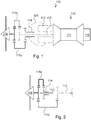
- the figure 1 schematically presents the general principle of a propulsion unit 100 according to the invention.
- the propeller propulsion unit 100 by definition comprises at least one kinematic system 110 and one electrical system 120.
- the kinematic system comprises the propeller and the main elements positioned behind the propeller and to which they are attached mechanically, or even kinematically.
- the heat engine 111 consuming fuel is for example an internal combustion heat engine, such as a gas turbine or combustion turbine.
- the electrical system 120 mainly comprises electrical and / or electronic elements.
- the electrical system 120 is configured to transmit electrical energy from the electrical energy generator 113 to the electric motor 114.
- It comprises for example at least cables or other connecting elements, referenced indifferently by the reference 124, making it possible to transmitting electric power from the electric power generator 113 to the electric motor 114.
- the first configuration 115a is involved, whereas in the event of a need for overpower, for example during take-off of an aircraft or during a special maneuver, or in the event of a need for overpowering.
- emergency for example in the event of failure of the electric motor and / or of the generator, the second configuration 115b can be put into operation.
- the training and selection device 115 is therefore configured to take each of the two configurations as desired.
- the example of the figure 1 illustrates a series kinematic architecture in which the primary shaft 112 passes through the electric power generator 113 then the electric motor 114.
- the electric motor 114 and the electric power generator 113 are mounted on the primary shaft 112 and the electrical energy generator is positioned between the electric motor 114 and the heat engine 111.
- the electrical energy generator 113 is here mounted at the output of the heat engine 111.
- the primary shaft 112 comprises for example a pinion, or any other type of toothed wheel (even including a crown), configured to couple to a coupling element of the drive and selection device 115 in the second configuration 115b.
- the pinion, or any other type of toothed wheel (even including a ring gear), of the primary shaft 112 is then located between the propeller 116 and the rotating element at the output of the electric motor 114.
- the rotary element at the output of the electric motor 114 is for example a shaft, here called secondary shaft, optionally provided with a pinion, or any other type of toothed wheel (even including a ring gear).
- the rotary element at the output of the electric motor 114 is for example the element configured to couple to a coupling element of the drive and selection device 115 in the first configuration 115a.
- the drive and selection device 115 comprises at least one coupling element configured to couple either to the primary shaft 112 or to the rotary element at the output of the electric motor 114.
- figure 5 it may be a single coupling element (referenced 119 on this figure 5 ) configured to take two positions (115a or 115b, in which it is partially shown in dotted lines) allowing it to be coupled with either the primary shaft 112 or the output of the electric motor 114.
- the example of the figure 2 presents a variant of that of the figure 1 . It differs in that the electric motor 114 is mounted on a stator independent of the primary shaft 112. In this example, at least the rotary element at the output of the electric motor 114 is positioned between the propeller 116 and the pinion, or any other type of toothed wheel (even including a crown wheel), of the primary shaft 112.
- the rotating element at the output of the electric motor and the pinion, or any other type of toothed wheel (even including a ring gear), of the primary shaft 112 could however be at the same distance behind the. propeller to drive the propeller.
- the electric energy generator 113 powered by the heat engine 111 is only dedicated to the production of electricity and does not produce any useful thrust in the kinematic system 110 of the propeller propulsion unit 100.
- the figure 3 shows schematically in a more complete manner a propulsion unit 100 according to an exemplary embodiment of the invention.
- the kinematics system can also include a gas exhaust duct 118.
- Such a gas exhaust duct 118 is typically positioned behind the heat engine 111.
- an internal surface of the gas exhaust duct 118 (that is to say that intended to be in contact with exhaust gas) can have an active surface for treating the exhaust gases in order to reduce the emission of pollutants into the atmosphere.
- the active surface of the exhaust gas duct interacts with the exhaust gases to process them.
- this active surface can be produced by catalytic deposition similar to those used in the exhaust pipes of motor vehicles.
- Such an active surface is suitable for directly treating the exhaust gases leaving the heat engine, and in particular the gases resulting from the combustion of a turbine.
- This figure 3 furthermore makes it possible to illustrate the principle of arrangement of the electrical system 120 with respect to the kinematic system 110.
- the electrical system 120 may include other elements.
- the electrical energy generator 113 is suitable for supplying the storage and electrical supply means 121.
- the electrical storage and supply means 121 consist for example of at least one battery suitable for storing the electrical energy coming from the electrical energy generator 113. It is for example several batteries in parallel.
- the electric storage and supply means 121 are used to supply at least the electric motor 114 with electric current.
- they also serve to ensure a sufficient electrical supply of the electric motor in the event of failure of the electrical energy generator 113.
- the figure 3 also illustrates the fact that the propeller propulsion unit may include a cooling system 130.
- the cooling system 130 is configured to cool at least part of the kinematic system 110 and / or the electrical system 120.
- the figure 4 shows a particular example of an arrangement comprising a propeller propulsion unit according to an exemplary embodiment of the invention, for example as described above, and an electric propeller motor 200, with a view to their installation in an aircraft.
- the propeller electric motor 200 here comprises an electric motor 201 and a propeller 202, as well as possibly any element (such as for example a gear train) useful for adapting the speed of rotation between an output of the electric motor and the propeller.
- the electric propeller motor 200 here denotes a unit without its own heat engine.
- At least the electric energy generator 113 of the kinematic system 110 of the propeller propulsion unit according to the invention is configured to power the electric propeller motor 200, in addition to the electric motor. 114 of the kinematic system 110 of the propeller propulsion unit itself. Thus, in other words for example, the electric energy generator 113 then feeds two electric motors.
- the electric energy generator 113 is electrically connected, by at least one electrical connection (which is here represented diagrammatically by a thick line), to the electric motor 201 of the electric propeller motor 200.
- the electrical system 120 of the propeller propulsion unit 100 comprises an additional electrical connection configured to connect the storage and electrical supply means 121, or even the alternator 123, to the electric motor 201 of the engine. electric propeller 200.
- the figure 5 shows on the one hand an example of a kinematic diagram and on the other hand a block diagram illustrating the operation of the propeller propulsion unit.
- the heat engine 111 drives the primary shaft 112 in rotation.
- the primary shaft 112 passes through the electric power generator 113 and the electric motor 114 and comprises, here beyond the electric motor 114, a toothed wheel, of the pinion type for example.
- the electric energy generator 113 and the electric motor 114 are for example connected to the primary shaft 112 by pivot connections.
- the heat engine 111 and the electric energy generator 113 are fixed, for example with respect to a reference (the latter possibly being a casing for example, and / or an aircraft in which they are arranged).
- the electric motor 114 supplied by the electric energy generator 113 is here represented by its rotating element at the output, for example a toothed wheel (for example of the pinion type).
- the drive and selection device 115 here comprises a coupling element 119.
- the coupling element 119 is configured to couple either to the primary shaft 112, in particular here to its toothed wheel, or to the rotary element at the output of the electric motor 114, in particular here to its cogwheel.
- the coupling element 119 comprises here for example a shaft provided with a toothed wheel, which, by translation of the shaft and / or the toothed wheel relative to the shaft, can be coupled either to the wheel toothed of the primary shaft (second configuration 115b in which the toothed wheel is shown in dotted lines), or to the toothed wheel at the output of the electric motor 114 (first configuration 115a in which the toothed wheel is shown in solid lines).
- the training and selection device 115 can comprise a single coupling element 119 configured to take the first configuration 115a or the second configuration 115b.
- the drive and selection device 115 may also include a guide element 117.
- the drive and selection device 115 is here represented very schematically by the guide element 117 and the coupling element 119.
- the guide element 117 shown here in a very simplified manner, makes it possible for example to adapt the speed of rotation of the coupling element 119 to a desired speed of rotation for the propeller 116.
- the propeller 116 here comprises a ring configured to couple at the output of the drive and selection device 115.
- the propeller can be coupled at the output of the shaft of the shaft. 'coupling element 119 for example.
- the propeller is for example connected by a pivot connection to a fixed axis, for example with respect to a reference (the latter possibly being a casing for example and / or the aircraft, or even the same as that mentioned above).
- the block diagram of the figure 5 illustrates the operation of a propeller propulsion unit according to the invention from a point of view "Electric", although for clarity kinematic elements are represented.
- fuel F is injected into the heat engine 111 which, by rotating the primary shaft (at angular speed w for example) supplies the electric energy generator 113 which generates an alternating current (AC).
- AC alternating current
- the rectifier 122 transforms the alternating current (AC) into direct current (DC) which is routed to the storage and electrical supply means 121 by means of cables or other connecting elements, referenced indifferently by the reference 124.
- the electrical storage and supply means 121 supply a direct current (DC) to the alternator 123 which transforms this direct current (DC) into alternating current (AC) to supply the electric motor 114.
- DC direct current
- AC alternating current
- the electric motor 114 then provides a rotary movement at the output, for example at angular speed ⁇ ', which may nevertheless be the same as that of the heat engine.
- the drive and selection device 115 is configured to take a first configuration 115a in which it is coupled at the output of the electric motor 114 and a second configuration 115b in which it is coupled at the output of the heat engine 111 (ie in particular to the primary shaft).
- the propeller 116 is driven in rotation by the drive and selection device 115.
- the figures 6 to 8 make it possible to represent a digital model corresponding to the kinematic system of the propeller propulsion unit of the figure 3 , in particular according to the arrangement of the figure 2 , that is to say where the electric motor 114 is mounted on a stator independent of the primary shaft 112.
- the drive and selection device 115 comprises an outlet to which the propeller is coupled.
- the figures 9 and 10 present an aircraft according to an exemplary embodiment of the invention.
- the aircraft described below is a transonic aircraft intended for the transport of passengers, and for example allowing, in certain interior layout configurations, the transport of at least one hundred passengers.
- the present invention is not limited to such an aircraft and may also relate to aircraft most commonly referred to as “cargo aircraft”.
- the aircraft 300 mainly comprises a fuselage 301 and a wing attached to the fuselage.
- the wing has two wings 302 extending symmetrically on either side of the fuselage 301.
- the fuselage has a front part, a central part and a rear part.
- An empennage 303 is attached to the fuselage 301 in particular to its rear part.
- the front part of the fuselage here comprises a cockpit 304 inside which there is a cockpit.
- the latter comprises in particular all the control elements for piloting the aircraft, control screens, means of communication, etc.
- the cockpit can be placed elsewhere than in the front part of the fuselage.
- the front part of the fuselage can then be intended for transporting a payload.
- the central part of the fuselage is mainly intended for the transport of a payload.
- the central part of the fuselage then mainly comprises a cabin intended to receive the passengers and a hold to receive the luggage of the passengers and possibly other goods, arranged under the cabin.
- the aircraft 300 comprises a propeller propulsion unit comprising at least some of the characteristics described above.
- the heat engine is for example a gas turbine using as fuel a fuel on board the aircraft, and typically kerosene stored in an aircraft tank.
- the kinematic system 110 of the propeller propulsion unit is arranged under a wing 302.
- the aircraft here comprises a kinematic system 110 under each wing 302, on either side of the fuselage 301.
- the aircraft further comprises an electric motor with a propeller 200 and in particular here an electric motor with a propeller 200 under each wing 302, on either side of the fuselage 301.
- each propeller electric motor 200 is powered by the electrical storage and supply means 121 which are charged by the electrical energy generator 113 of each of the kinematic systems 110 arranged in the aircraft.
- the electrical storage and power supply means 121 are arranged in the fuselage, close to the center of gravity of the aircraft.
- each kinematic system 110 is positioned between the corresponding electric propeller motor 200 and the fuselage 301.
- This configuration allows a better distribution of the loads.
- each electric propeller motor 200 is positioned between the fuselage 301 and the corresponding kinematic system 110.
- FIGS 11 and 12 illustrate means for fixing a kinematic system 110 according to the invention under a wing 302.
- figure 11 it is about a 305 nacelle whereas in the example of the figure 12 it may be a “turbofan” 306 type attachment.
Landscapes
- Engineering & Computer Science (AREA)
- Aviation & Aerospace Engineering (AREA)
- Mechanical Engineering (AREA)
- General Engineering & Computer Science (AREA)
- Chemical & Material Sciences (AREA)
- Combustion & Propulsion (AREA)
- Connection Of Motors, Electrical Generators, Mechanical Devices, And The Like (AREA)
Claims (12)
- Propellerantriebseinheit (100), die mindestens ein Kinematiksystem (110) aufweist, das mindestens enthält:• einen Treibstoff verbrauchenden Wärmekraftmotor (111) und eine Primärwelle (112), die am Ausgang des Wärmekraftmotors in Drehung versetzt wird,• einen Elektroenergieerzeuger (113), der konfiguriert ist, eine elektrische Energie ausgehend von der Drehung der Primärwelle (112) zu erzeugen,• einen Elektromotor (114), der konfiguriert ist, eine Drehbewegung am Ausgang ausgehend von der vom Elektroenergieerzeuger (113) erzeugten elektrischen Energie zu erzeugen,dadurch gekennzeichnet, dass sie enthält:• eine Antriebs- und Auswahlvorrichtung (115), die ein Kupplungselement (119), das konfiguriert ist, sich entweder an die Primärwelle (112) oder an ein drehendes Element am Ausgang des Elektromotors (114) anzukuppeln, und ein Führungselement (117) aufweist, das konfiguriert ist, das Kupplungselement (119) zumindest in Drehung zu führen, damit es wahlweise annimmt• eine erste Konfiguration (115a), in der es am Ausgang des Elektromotors (114) angekuppelt ist, und• eine zweite Konfiguration (115b), in der es an die Primärwelle (112) des Wärmekraftmotors angekuppelt ist,• einen Propeller (116), der von der Antriebs- und Auswahlvorrichtung (115) in Drehung versetzt wird, wobei das Führungselement (117) es ermöglicht, die Drehgeschwindigkeit des Kupplungselements (119) an eine für den Propeller (116) gewünschte Drehgeschwindigkeit anzupassen.
- Propellerantriebseinheit nach Anspruch 1, dadurch gekennzeichnet, dass das Kupplungselement (119) ein Element ist, von dem mindestens ein Teil zwischen einer Stellung, in der es an die Primärwelle (112) des Wärmekraftmotors (111) angekuppelt ist, und einer Stellung beweglich ist, in der es an den Ausgang des Elektromotors (114) angekuppelt ist.
- Propellerantriebseinheit nach einem der Ansprüche 1 oder 2, dadurch gekennzeichnet, dass das Führungselement ein Element ist, das konfiguriert ist, mindestens das Kupplungselement (119) zwischen der Konfiguration, in der es an die Primärwelle (112) des Wärmekraftmotors (111) angekuppelt ist, und der Konfiguration zu führen, in der es an den Ausgang des Elektromotors (114) angekuppelt ist, ohne seine Drehung zu blockieren.
- Propellerantriebseinheit nach einem der Ansprüche 1 bis 3, dadurch gekennzeichnet, dass der Treibstoff verbrauchende Wärmekraftmotor (111) ein Wärmekraftmotor mit innerer Verbrennung wie eine Gasturbine oder eine Verbrennungsturbine ist.
- Propellerantriebseinheit nach einem der Ansprüche 1 bis 4, dadurch gekennzeichnet, dass sie außerdem Stromspeicher- und Versorgungseinrichtungen (121) aufweist, die konfiguriert sind, die vom Elektroenergieerzeuger (113) erzeugte elektrische Energie zu speichern und den Elektromotor (114) mit elektrischer Energie zu versorgen.
- Propellerantriebseinheit nach einem der Ansprüche 1 bis 5, dadurch gekennzeichnet, dass sie außerdem einen Gleichrichter (122), der konfiguriert ist, einen Wechselstrom am Ausgang des Elektroenergieerzeugers (113) in Gleichstrom umzuwandeln, und einen Wechselrichter (123) aufweist, der konfiguriert ist, einen Gleichstrom in einen Wechselstrom umzuwandeln, um den Elektromotor (114) zu versorgen.
- Luftfahrzeug (300), das mindestens eine Propellerantriebseinheit (100) nach einem der Ansprüche 1 bis 6 aufweist.
- Luftfahrzeug (300) nach Anspruch 7, dadurch gekennzeichnet, dass es mindestens einen Flügel (302) aufweist, und dass das Kinematiksystem (110) unter dem Flügel angeordnet ist.
- Luftfahrzeug (300) nach einem der Ansprüche 7 oder 8, dadurch gekennzeichnet, dass die Stromspeicher- und Versorgungseinrichtungen in einem Rumpf (301) des Luftfahrzeugs angeordnet sind.
- Luftfahrzeug (300) nach einem der Ansprüche 7 bis 9, dadurch gekennzeichnet, dass die Stromspeicher- und Versorgungseinrichtungen (121) in der Nähe des Schwerpunkts des Luftfahrzeugs angeordnet sind, das mindestens mit dem Kinematiksystem (110) ausgestattet ist.
- Luftfahrzeug (300) nach einem der Ansprüche 7 bis 10, dadurch gekennzeichnet, dass es außerdem einen elektrischen Propellermotor (200) aufweist, und dass der Wärmekraftmotor (111) und der Elektroenergieerzeuger (113) der Propellerantriebseinheit (100) konfiguriert sind, außerdem elektrische Energie an den elektrischen Propellermotor (200) zu liefern.
- Luftfahrzeug (300) nach Anspruch 11, dadurch gekennzeichnet, dass es außerdem einen Rumpf (301) aufweist, und dass der elektrische Propellermotor (200) unter dem Flügel (302) angeordnet ist, und dass das Kinematiksystem (110) zwischen dem elektrischen Propellermotor (200) und dem Rumpf (301) positioniert ist.
Applications Claiming Priority (1)
| Application Number | Priority Date | Filing Date | Title |
|---|---|---|---|
| FR1852804A FR3079498B1 (fr) | 2018-03-30 | 2018-03-30 | Unite de propulsion a helice comprenant un moteur thermique et un moteur electrique et aeronef comportant une telle unite de propulsion a helice |
Publications (2)
| Publication Number | Publication Date |
|---|---|
| EP3546366A1 EP3546366A1 (de) | 2019-10-02 |
| EP3546366B1 true EP3546366B1 (de) | 2021-09-22 |
Family
ID=62751076
Family Applications (1)
| Application Number | Title | Priority Date | Filing Date |
|---|---|---|---|
| EP19165911.9A Active EP3546366B1 (de) | 2018-03-30 | 2019-03-28 | Propellerantriebseinheit, die einen verbrennungsmotor und einen elektromotor umfasst, sowie eine solche propellerantriebseinheit umfassendes luftfahrzeug |
Country Status (4)
| Country | Link |
|---|---|
| US (1) | US11897622B2 (de) |
| EP (1) | EP3546366B1 (de) |
| CN (1) | CN110316387A (de) |
| FR (1) | FR3079498B1 (de) |
Families Citing this family (7)
| Publication number | Priority date | Publication date | Assignee | Title |
|---|---|---|---|---|
| GB2587669A (en) * | 2019-10-02 | 2021-04-07 | Advanced Mobility Res And Development Ltd | Systems and methods for aircraft |
| GB201918281D0 (en) * | 2019-12-12 | 2020-01-29 | Rolls Royce Plc | Aircraft hybrid propulsion system |
| FR3108891B1 (fr) * | 2020-04-01 | 2022-05-06 | Safran | Système de propulsion pour aéronef à voilure fixe, et aéronef associé |
| US11408340B2 (en) * | 2020-05-15 | 2022-08-09 | Pratt & Whitney Canada Corp. | Twin-engine system with electric drive |
| US11448135B2 (en) * | 2020-07-23 | 2022-09-20 | Ge Aviation Systems Llc | Systems and methods of power allocation for turboprop and turboshaft aircraft |
| US20240208663A1 (en) * | 2022-12-23 | 2024-06-27 | Pratt & Whitney Canada Corp. | Hybrid aircraft propulsion system with remotely located electric machine |
| WO2025239948A2 (en) * | 2024-05-17 | 2025-11-20 | Archer Aviation Inc. | Motor gearbox assembly with layshaft for evtol aircraft |
Family Cites Families (24)
| Publication number | Priority date | Publication date | Assignee | Title |
|---|---|---|---|---|
| US2462201A (en) * | 1943-02-02 | 1949-02-22 | Westinghouse Electric Corp | Electrical airplane propulsion |
| DE10110513A1 (de) | 2001-01-29 | 2002-12-12 | Ulrich Werth | Implantat und Verfahren und Vorrichtung zum Einsetzen des Implantats in lebendes Gewebe |
| WO2006113877A2 (en) * | 2005-04-20 | 2006-10-26 | Lugg Richard H | Hybrid jet/electric vtol aircraft |
| DE102006055426A1 (de) | 2006-11-22 | 2008-05-29 | Evonik Röhm Gmbh | Verfahren zur Herstellung von Alkyl(meth)acrylaten unter Verwendung einer enzymatischen Cyanhydrinhydrolyse |
| US8706330B2 (en) * | 2008-11-14 | 2014-04-22 | Hybrid Innovation Technologies Llc | Electronic system and method of automating, controlling, and optimizing the operation of one or more energy storage units and a combined serial and parallel hybrid marine propulsion system |
| GB0903423D0 (en) * | 2009-03-02 | 2009-04-08 | Rolls Royce Plc | Variable drive gas turbine engine |
| FR2945268B1 (fr) * | 2009-05-05 | 2013-05-17 | Airbus France | Generateur electrique sur une partie tournante de turbopropulseur |
| DE102010021026A1 (de) * | 2010-05-19 | 2011-11-24 | Eads Deutschland Gmbh | Hybrides Antriebs- und Energiesystem für Fluggeräte |
| DE102012209807A1 (de) * | 2012-06-12 | 2013-12-12 | Siemens Aktiengesellschaft | Flugzeug und Verfahren zum Herstellen eines Flugzeugs |
| FR2992630B1 (fr) * | 2012-06-29 | 2015-02-20 | Turbomeca | Procede et configuration d'apport d'energie propulsive et/ou non propulsive dans une architecture d'helicoptere par un moteur auxiliaire de puissance |
| CA2820254C (en) * | 2012-07-09 | 2020-02-18 | Mcmaster University | Hybrid powertrain system |
| ES2500015B1 (es) * | 2013-02-28 | 2015-06-23 | Axter Aerospace S.L. | Sistema de potencia auxiliar eléctrico para aeronaves de motor de pistón |
| FR3006997B1 (fr) | 2013-06-14 | 2016-12-23 | Airbus | Aeronef a moyens de propulsion electriques |
| US9643729B2 (en) * | 2014-06-20 | 2017-05-09 | Electronair Llc | Energy cell regenerative system for electrically powered aircraft |
| FR3023989B1 (fr) | 2014-07-17 | 2016-08-26 | Airbus Helicopters | Architecture electrique d'un aeronef, aeronef et procede mis en oeuvre |
| WO2016049027A1 (en) * | 2014-09-23 | 2016-03-31 | Sikorsky Aircraft Corporation | Hybrid electric power drive system for a rotorcraft |
| FR3029172B1 (fr) * | 2014-11-27 | 2018-05-25 | Safran Helicopter Engines | Groupe propulseur a moyens d'accouplement selectif |
| DE102014224637B4 (de) * | 2014-12-02 | 2022-12-29 | Georgi Atanasov | Hybrid-Elektro-Antriebssystem für ein Flugzeug |
| US10717539B2 (en) * | 2016-05-05 | 2020-07-21 | Pratt & Whitney Canada Corp. | Hybrid gas-electric turbine engine |
| CN105909377B (zh) * | 2016-05-06 | 2018-10-23 | 王领军 | 一种共轴油电混合动力发动机 |
| US10604266B2 (en) * | 2016-05-16 | 2020-03-31 | Rolls-Royce Corporation | Electrical assist for aircraft |
| CN206072309U (zh) * | 2016-08-05 | 2017-04-05 | 重庆隆旺机电有限责任公司 | 双动力传动系统 |
| CN106184779A (zh) * | 2016-09-19 | 2016-12-07 | 中电科芜湖钻石飞机设计研究院有限公司 | 一种混合动力飞机耦合系统 |
| DE202017006138U1 (de) * | 2017-11-28 | 2018-03-01 | Siegfried Alexander Eisenmann | Universalfluggerät mit Elektroantrieb |
-
2018
- 2018-03-30 FR FR1852804A patent/FR3079498B1/fr not_active Expired - Fee Related
-
2019
- 2019-03-28 EP EP19165911.9A patent/EP3546366B1/de active Active
- 2019-03-28 US US16/368,305 patent/US11897622B2/en active Active
- 2019-03-29 CN CN201910250550.1A patent/CN110316387A/zh active Pending
Also Published As
| Publication number | Publication date |
|---|---|
| CN110316387A (zh) | 2019-10-11 |
| FR3079498B1 (fr) | 2020-06-19 |
| US20190300186A1 (en) | 2019-10-03 |
| US11897622B2 (en) | 2024-02-13 |
| EP3546366A1 (de) | 2019-10-02 |
| FR3079498A1 (fr) | 2019-10-04 |
Similar Documents
| Publication | Publication Date | Title |
|---|---|---|
| EP3546366B1 (de) | Propellerantriebseinheit, die einen verbrennungsmotor und einen elektromotor umfasst, sowie eine solche propellerantriebseinheit umfassendes luftfahrzeug | |
| EP2404775B1 (de) | Elektrische Architektur eines Drehflüglers mit Hybrid Motorisierung und Verfahren | |
| EP2981470B1 (de) | System zur rückgewinnung und umwandlung von kinetischer energie und potenzialenergie in elektrische energie für ein flugzeug | |
| EP2750969B1 (de) | Luftfahrzeug mit aus mehreren elektromotoren mit freilauf bestehendem antrieb | |
| EP3599140A1 (de) | Verfahren und vorrichtung zur verwaltung der energie einer hybrid-triebwerksanlage eines multirotor-luftfahrzeugs | |
| FR2980771A1 (fr) | Aeronef hybride a voilure tournante | |
| CA2876952A1 (fr) | Procede et configuration d'apport d'energie propulsive et/ou non propulsive dans une architecture d'helicoptere par un moteur auxiliaire de puissance | |
| EP3787967B1 (de) | Antriebssystem für einen hubschrauber | |
| FR2966804A1 (fr) | Aerodyne comprenant des trains d'atterrissage motorises | |
| EP3883854B1 (de) | Antriebssystem eines flugzeugs und verfahren zum betreiben eines solchen systems | |
| FR2864030A1 (fr) | Aeronef convertible pourvu de deux "tilt fan" de part et d'autre du fuselage et d'un troisieme "tilt fan" agence sur la queue de l'aeronef | |
| FR2957207A1 (fr) | Groupe electromoteur distribue. | |
| FR3096659A1 (fr) | Engin comprenant un groupe motopropulseur hybride et procédé de pilotage correspondant | |
| EP3861614B1 (de) | Elektrische architektur für hybridantrieb | |
| FR3110896A1 (fr) | Architecture électrique d’un aéronef | |
| FR2976555A1 (fr) | Recuperation d'energie electrique sur une helice d'aeronef | |
| FR3092926A1 (fr) | Aéronef à décollage et atterrissage verticaux à propulsion hybride muni d’un système de gestion automatique d’énergie embarqué | |
| EP4551428B1 (de) | Elektrischer antriebsstrang für flugzeug und verfahren zum laden einer batterie eines flugzeugs | |
| EP3828082A1 (de) | Hybrid-drehflügelflugzeug mit mindestens einem propeller in pusher- oder tractor-konfiguration, und entsprechendes steuerungsverfahren | |
| EP4313764B1 (de) | Kampfflugzeug mit elektrischem waffensystem mit optimiertem energiemanagement | |
| FR3133592A1 (fr) | Turbomachine améliorée pour aéronef hybridé | |
| WO2018055287A1 (fr) | Unité d'alimentation en air sous pression pour aéronef | |
| FR3120053A1 (fr) | Procede pour faire fonctionner un aeronef en fonction d’un mode de fonctionnement | |
| WO2021250330A1 (fr) | Chaîne de puissance électrique à double alimentation hybride pour avion mono-hélice | |
| WO2020025885A1 (fr) | Aeronef a decollage et atterrissage vertical |
Legal Events
| Date | Code | Title | Description |
|---|---|---|---|
| PUAI | Public reference made under article 153(3) epc to a published international application that has entered the european phase |
Free format text: ORIGINAL CODE: 0009012 |
|
| STAA | Information on the status of an ep patent application or granted ep patent |
Free format text: STATUS: THE APPLICATION HAS BEEN PUBLISHED |
|
| AK | Designated contracting states |
Kind code of ref document: A1 Designated state(s): AL AT BE BG CH CY CZ DE DK EE ES FI FR GB GR HR HU IE IS IT LI LT LU LV MC MK MT NL NO PL PT RO RS SE SI SK SM TR |
|
| AX | Request for extension of the european patent |
Extension state: BA ME |
|
| STAA | Information on the status of an ep patent application or granted ep patent |
Free format text: STATUS: REQUEST FOR EXAMINATION WAS MADE |
|
| 17P | Request for examination filed |
Effective date: 20200302 |
|
| RBV | Designated contracting states (corrected) |
Designated state(s): AL AT BE BG CH CY CZ DE DK EE ES FI FR GB GR HR HU IE IS IT LI LT LU LV MC MK MT NL NO PL PT RO RS SE SI SK SM TR |
|
| STAA | Information on the status of an ep patent application or granted ep patent |
Free format text: STATUS: EXAMINATION IS IN PROGRESS |
|
| 17Q | First examination report despatched |
Effective date: 20200731 |
|
| GRAP | Despatch of communication of intention to grant a patent |
Free format text: ORIGINAL CODE: EPIDOSNIGR1 |
|
| STAA | Information on the status of an ep patent application or granted ep patent |
Free format text: STATUS: GRANT OF PATENT IS INTENDED |
|
| INTG | Intention to grant announced |
Effective date: 20210423 |
|
| GRAS | Grant fee paid |
Free format text: ORIGINAL CODE: EPIDOSNIGR3 |
|
| GRAA | (expected) grant |
Free format text: ORIGINAL CODE: 0009210 |
|
| STAA | Information on the status of an ep patent application or granted ep patent |
Free format text: STATUS: THE PATENT HAS BEEN GRANTED |
|
| AK | Designated contracting states |
Kind code of ref document: B1 Designated state(s): AL AT BE BG CH CY CZ DE DK EE ES FI FR GB GR HR HU IE IS IT LI LT LU LV MC MK MT NL NO PL PT RO RS SE SI SK SM TR |
|
| REG | Reference to a national code |
Ref country code: GB Ref legal event code: FG4D Free format text: NOT ENGLISH |
|
| REG | Reference to a national code |
Ref country code: IE Ref legal event code: FG4D Free format text: LANGUAGE OF EP DOCUMENT: FRENCH |
|
| REG | Reference to a national code |
Ref country code: DE Ref legal event code: R096 Ref document number: 602019007780 Country of ref document: DE |
|
| REG | Reference to a national code |
Ref country code: CH Ref legal event code: EP Ref country code: AT Ref legal event code: REF Ref document number: 1432154 Country of ref document: AT Kind code of ref document: T Effective date: 20211015 |
|
| REG | Reference to a national code |
Ref country code: LT Ref legal event code: MG9D |
|
| REG | Reference to a national code |
Ref country code: NL Ref legal event code: MP Effective date: 20210922 |
|
| PG25 | Lapsed in a contracting state [announced via postgrant information from national office to epo] |
Ref country code: SE Free format text: LAPSE BECAUSE OF FAILURE TO SUBMIT A TRANSLATION OF THE DESCRIPTION OR TO PAY THE FEE WITHIN THE PRESCRIBED TIME-LIMIT Effective date: 20210922 Ref country code: RS Free format text: LAPSE BECAUSE OF FAILURE TO SUBMIT A TRANSLATION OF THE DESCRIPTION OR TO PAY THE FEE WITHIN THE PRESCRIBED TIME-LIMIT Effective date: 20210922 Ref country code: FI Free format text: LAPSE BECAUSE OF FAILURE TO SUBMIT A TRANSLATION OF THE DESCRIPTION OR TO PAY THE FEE WITHIN THE PRESCRIBED TIME-LIMIT Effective date: 20210922 Ref country code: NO Free format text: LAPSE BECAUSE OF FAILURE TO SUBMIT A TRANSLATION OF THE DESCRIPTION OR TO PAY THE FEE WITHIN THE PRESCRIBED TIME-LIMIT Effective date: 20211222 Ref country code: HR Free format text: LAPSE BECAUSE OF FAILURE TO SUBMIT A TRANSLATION OF THE DESCRIPTION OR TO PAY THE FEE WITHIN THE PRESCRIBED TIME-LIMIT Effective date: 20210922 Ref country code: BG Free format text: LAPSE BECAUSE OF FAILURE TO SUBMIT A TRANSLATION OF THE DESCRIPTION OR TO PAY THE FEE WITHIN THE PRESCRIBED TIME-LIMIT Effective date: 20211222 Ref country code: LT Free format text: LAPSE BECAUSE OF FAILURE TO SUBMIT A TRANSLATION OF THE DESCRIPTION OR TO PAY THE FEE WITHIN THE PRESCRIBED TIME-LIMIT Effective date: 20210922 |
|
| REG | Reference to a national code |
Ref country code: AT Ref legal event code: MK05 Ref document number: 1432154 Country of ref document: AT Kind code of ref document: T Effective date: 20210922 |
|
| PG25 | Lapsed in a contracting state [announced via postgrant information from national office to epo] |
Ref country code: LV Free format text: LAPSE BECAUSE OF FAILURE TO SUBMIT A TRANSLATION OF THE DESCRIPTION OR TO PAY THE FEE WITHIN THE PRESCRIBED TIME-LIMIT Effective date: 20210922 Ref country code: GR Free format text: LAPSE BECAUSE OF FAILURE TO SUBMIT A TRANSLATION OF THE DESCRIPTION OR TO PAY THE FEE WITHIN THE PRESCRIBED TIME-LIMIT Effective date: 20211223 |
|
| PG25 | Lapsed in a contracting state [announced via postgrant information from national office to epo] |
Ref country code: AT Free format text: LAPSE BECAUSE OF FAILURE TO SUBMIT A TRANSLATION OF THE DESCRIPTION OR TO PAY THE FEE WITHIN THE PRESCRIBED TIME-LIMIT Effective date: 20210922 |
|
| PG25 | Lapsed in a contracting state [announced via postgrant information from national office to epo] |
Ref country code: IS Free format text: LAPSE BECAUSE OF FAILURE TO SUBMIT A TRANSLATION OF THE DESCRIPTION OR TO PAY THE FEE WITHIN THE PRESCRIBED TIME-LIMIT Effective date: 20220122 Ref country code: SK Free format text: LAPSE BECAUSE OF FAILURE TO SUBMIT A TRANSLATION OF THE DESCRIPTION OR TO PAY THE FEE WITHIN THE PRESCRIBED TIME-LIMIT Effective date: 20210922 Ref country code: RO Free format text: LAPSE BECAUSE OF FAILURE TO SUBMIT A TRANSLATION OF THE DESCRIPTION OR TO PAY THE FEE WITHIN THE PRESCRIBED TIME-LIMIT Effective date: 20210922 Ref country code: PT Free format text: LAPSE BECAUSE OF FAILURE TO SUBMIT A TRANSLATION OF THE DESCRIPTION OR TO PAY THE FEE WITHIN THE PRESCRIBED TIME-LIMIT Effective date: 20220124 Ref country code: PL Free format text: LAPSE BECAUSE OF FAILURE TO SUBMIT A TRANSLATION OF THE DESCRIPTION OR TO PAY THE FEE WITHIN THE PRESCRIBED TIME-LIMIT Effective date: 20210922 Ref country code: NL Free format text: LAPSE BECAUSE OF FAILURE TO SUBMIT A TRANSLATION OF THE DESCRIPTION OR TO PAY THE FEE WITHIN THE PRESCRIBED TIME-LIMIT Effective date: 20210922 Ref country code: ES Free format text: LAPSE BECAUSE OF FAILURE TO SUBMIT A TRANSLATION OF THE DESCRIPTION OR TO PAY THE FEE WITHIN THE PRESCRIBED TIME-LIMIT Effective date: 20210922 Ref country code: EE Free format text: LAPSE BECAUSE OF FAILURE TO SUBMIT A TRANSLATION OF THE DESCRIPTION OR TO PAY THE FEE WITHIN THE PRESCRIBED TIME-LIMIT Effective date: 20210922 Ref country code: CZ Free format text: LAPSE BECAUSE OF FAILURE TO SUBMIT A TRANSLATION OF THE DESCRIPTION OR TO PAY THE FEE WITHIN THE PRESCRIBED TIME-LIMIT Effective date: 20210922 Ref country code: AL Free format text: LAPSE BECAUSE OF FAILURE TO SUBMIT A TRANSLATION OF THE DESCRIPTION OR TO PAY THE FEE WITHIN THE PRESCRIBED TIME-LIMIT Effective date: 20210922 |
|
| REG | Reference to a national code |
Ref country code: DE Ref legal event code: R097 Ref document number: 602019007780 Country of ref document: DE |
|
| PG25 | Lapsed in a contracting state [announced via postgrant information from national office to epo] |
Ref country code: DK Free format text: LAPSE BECAUSE OF FAILURE TO SUBMIT A TRANSLATION OF THE DESCRIPTION OR TO PAY THE FEE WITHIN THE PRESCRIBED TIME-LIMIT Effective date: 20210922 |
|
| PLBE | No opposition filed within time limit |
Free format text: ORIGINAL CODE: 0009261 |
|
| STAA | Information on the status of an ep patent application or granted ep patent |
Free format text: STATUS: NO OPPOSITION FILED WITHIN TIME LIMIT |
|
| 26N | No opposition filed |
Effective date: 20220623 |
|
| PG25 | Lapsed in a contracting state [announced via postgrant information from national office to epo] |
Ref country code: MC Free format text: LAPSE BECAUSE OF FAILURE TO SUBMIT A TRANSLATION OF THE DESCRIPTION OR TO PAY THE FEE WITHIN THE PRESCRIBED TIME-LIMIT Effective date: 20210922 |
|
| REG | Reference to a national code |
Ref country code: CH Ref legal event code: PL |
|
| PG25 | Lapsed in a contracting state [announced via postgrant information from national office to epo] |
Ref country code: SI Free format text: LAPSE BECAUSE OF FAILURE TO SUBMIT A TRANSLATION OF THE DESCRIPTION OR TO PAY THE FEE WITHIN THE PRESCRIBED TIME-LIMIT Effective date: 20210922 |
|
| REG | Reference to a national code |
Ref country code: BE Ref legal event code: MM Effective date: 20220331 |
|
| PG25 | Lapsed in a contracting state [announced via postgrant information from national office to epo] |
Ref country code: LU Free format text: LAPSE BECAUSE OF NON-PAYMENT OF DUE FEES Effective date: 20220328 Ref country code: LI Free format text: LAPSE BECAUSE OF NON-PAYMENT OF DUE FEES Effective date: 20220331 Ref country code: IT Free format text: LAPSE BECAUSE OF FAILURE TO SUBMIT A TRANSLATION OF THE DESCRIPTION OR TO PAY THE FEE WITHIN THE PRESCRIBED TIME-LIMIT Effective date: 20210922 Ref country code: IE Free format text: LAPSE BECAUSE OF NON-PAYMENT OF DUE FEES Effective date: 20220328 Ref country code: CH Free format text: LAPSE BECAUSE OF NON-PAYMENT OF DUE FEES Effective date: 20220331 |
|
| PG25 | Lapsed in a contracting state [announced via postgrant information from national office to epo] |
Ref country code: BE Free format text: LAPSE BECAUSE OF NON-PAYMENT OF DUE FEES Effective date: 20220331 |
|
| PG25 | Lapsed in a contracting state [announced via postgrant information from national office to epo] |
Ref country code: SM Free format text: LAPSE BECAUSE OF FAILURE TO SUBMIT A TRANSLATION OF THE DESCRIPTION OR TO PAY THE FEE WITHIN THE PRESCRIBED TIME-LIMIT Effective date: 20210922 Ref country code: MK Free format text: LAPSE BECAUSE OF FAILURE TO SUBMIT A TRANSLATION OF THE DESCRIPTION OR TO PAY THE FEE WITHIN THE PRESCRIBED TIME-LIMIT Effective date: 20210922 Ref country code: CY Free format text: LAPSE BECAUSE OF FAILURE TO SUBMIT A TRANSLATION OF THE DESCRIPTION OR TO PAY THE FEE WITHIN THE PRESCRIBED TIME-LIMIT Effective date: 20210922 |
|
| PG25 | Lapsed in a contracting state [announced via postgrant information from national office to epo] |
Ref country code: HU Free format text: LAPSE BECAUSE OF FAILURE TO SUBMIT A TRANSLATION OF THE DESCRIPTION OR TO PAY THE FEE WITHIN THE PRESCRIBED TIME-LIMIT; INVALID AB INITIO Effective date: 20190328 |
|
| PG25 | Lapsed in a contracting state [announced via postgrant information from national office to epo] |
Ref country code: TR Free format text: LAPSE BECAUSE OF FAILURE TO SUBMIT A TRANSLATION OF THE DESCRIPTION OR TO PAY THE FEE WITHIN THE PRESCRIBED TIME-LIMIT Effective date: 20210922 |
|
| PG25 | Lapsed in a contracting state [announced via postgrant information from national office to epo] |
Ref country code: MT Free format text: LAPSE BECAUSE OF FAILURE TO SUBMIT A TRANSLATION OF THE DESCRIPTION OR TO PAY THE FEE WITHIN THE PRESCRIBED TIME-LIMIT Effective date: 20210922 |
|
| PGFP | Annual fee paid to national office [announced via postgrant information from national office to epo] |
Ref country code: GB Payment date: 20260324 Year of fee payment: 8 |
|
| PGFP | Annual fee paid to national office [announced via postgrant information from national office to epo] |
Ref country code: DE Payment date: 20260319 Year of fee payment: 8 |
|
| PGFP | Annual fee paid to national office [announced via postgrant information from national office to epo] |
Ref country code: FR Payment date: 20260320 Year of fee payment: 8 |