EP3546779B1 - Joint homocinétique à tripode - Google Patents
Joint homocinétique à tripode Download PDFInfo
- Publication number
- EP3546779B1 EP3546779B1 EP17884535.0A EP17884535A EP3546779B1 EP 3546779 B1 EP3546779 B1 EP 3546779B1 EP 17884535 A EP17884535 A EP 17884535A EP 3546779 B1 EP3546779 B1 EP 3546779B1
- Authority
- EP
- European Patent Office
- Prior art keywords
- ball
- joint member
- outer joint
- open side
- track
- Prior art date
- Legal status (The legal status is an assumption and is not a legal conclusion. Google has not performed a legal analysis and makes no representation as to the accuracy of the status listed.)
- Active
Links
Images



Classifications
-
- F—MECHANICAL ENGINEERING; LIGHTING; HEATING; WEAPONS; BLASTING
- F16—ENGINEERING ELEMENTS AND UNITS; GENERAL MEASURES FOR PRODUCING AND MAINTAINING EFFECTIVE FUNCTIONING OF MACHINES OR INSTALLATIONS; THERMAL INSULATION IN GENERAL
- F16C—SHAFTS; FLEXIBLE SHAFTS; ELEMENTS OR CRANKSHAFT MECHANISMS; ROTARY BODIES OTHER THAN GEARING ELEMENTS; BEARINGS
- F16C33/00—Parts of bearings; Special methods for making bearings or parts thereof
- F16C33/30—Parts of ball or roller bearings
- F16C33/306—Means to synchronise movements
-
- F—MECHANICAL ENGINEERING; LIGHTING; HEATING; WEAPONS; BLASTING
- F16—ENGINEERING ELEMENTS AND UNITS; GENERAL MEASURES FOR PRODUCING AND MAINTAINING EFFECTIVE FUNCTIONING OF MACHINES OR INSTALLATIONS; THERMAL INSULATION IN GENERAL
- F16D—COUPLINGS FOR TRANSMITTING ROTATION; CLUTCHES; BRAKES
- F16D3/00—Yielding couplings, i.e. with means permitting movement between the connected parts during the drive
- F16D3/16—Universal joints in which flexibility is produced by means of pivots or sliding or rolling connecting parts
- F16D3/20—Universal joints in which flexibility is produced by means of pivots or sliding or rolling connecting parts one coupling part entering a sleeve of the other coupling part and connected thereto by sliding or rolling members
- F16D3/202—Universal joints in which flexibility is produced by means of pivots or sliding or rolling connecting parts one coupling part entering a sleeve of the other coupling part and connected thereto by sliding or rolling members one coupling part having radially projecting pins, e.g. tripod joints
- F16D3/205—Universal joints in which flexibility is produced by means of pivots or sliding or rolling connecting parts one coupling part entering a sleeve of the other coupling part and connected thereto by sliding or rolling members one coupling part having radially projecting pins, e.g. tripod joints the pins extending radially outwardly from the coupling part
- F16D3/2055—Universal joints in which flexibility is produced by means of pivots or sliding or rolling connecting parts one coupling part entering a sleeve of the other coupling part and connected thereto by sliding or rolling members one coupling part having radially projecting pins, e.g. tripod joints the pins extending radially outwardly from the coupling part having three pins, i.e. true tripod joints
-
- F—MECHANICAL ENGINEERING; LIGHTING; HEATING; WEAPONS; BLASTING
- F16—ENGINEERING ELEMENTS AND UNITS; GENERAL MEASURES FOR PRODUCING AND MAINTAINING EFFECTIVE FUNCTIONING OF MACHINES OR INSTALLATIONS; THERMAL INSULATION IN GENERAL
- F16C—SHAFTS; FLEXIBLE SHAFTS; ELEMENTS OR CRANKSHAFT MECHANISMS; ROTARY BODIES OTHER THAN GEARING ELEMENTS; BEARINGS
- F16C29/00—Bearings for parts moving only linearly
- F16C29/04—Ball or roller bearings
-
- F—MECHANICAL ENGINEERING; LIGHTING; HEATING; WEAPONS; BLASTING
- F16—ENGINEERING ELEMENTS AND UNITS; GENERAL MEASURES FOR PRODUCING AND MAINTAINING EFFECTIVE FUNCTIONING OF MACHINES OR INSTALLATIONS; THERMAL INSULATION IN GENERAL
- F16C—SHAFTS; FLEXIBLE SHAFTS; ELEMENTS OR CRANKSHAFT MECHANISMS; ROTARY BODIES OTHER THAN GEARING ELEMENTS; BEARINGS
- F16C29/00—Bearings for parts moving only linearly
- F16C29/04—Ball or roller bearings
- F16C29/045—Ball or roller bearings having rolling elements journaled in one of the moving parts
- F16C29/046—Ball or roller bearings having rolling elements journaled in one of the moving parts with balls journaled in pockets
-
- F—MECHANICAL ENGINEERING; LIGHTING; HEATING; WEAPONS; BLASTING
- F16—ENGINEERING ELEMENTS AND UNITS; GENERAL MEASURES FOR PRODUCING AND MAINTAINING EFFECTIVE FUNCTIONING OF MACHINES OR INSTALLATIONS; THERMAL INSULATION IN GENERAL
- F16C—SHAFTS; FLEXIBLE SHAFTS; ELEMENTS OR CRANKSHAFT MECHANISMS; ROTARY BODIES OTHER THAN GEARING ELEMENTS; BEARINGS
- F16C2361/00—Apparatus or articles in engineering in general
- F16C2361/41—Couplings
-
- F—MECHANICAL ENGINEERING; LIGHTING; HEATING; WEAPONS; BLASTING
- F16—ENGINEERING ELEMENTS AND UNITS; GENERAL MEASURES FOR PRODUCING AND MAINTAINING EFFECTIVE FUNCTIONING OF MACHINES OR INSTALLATIONS; THERMAL INSULATION IN GENERAL
- F16D—COUPLINGS FOR TRANSMITTING ROTATION; CLUTCHES; BRAKES
- F16D3/00—Yielding couplings, i.e. with means permitting movement between the connected parts during the drive
- F16D3/16—Universal joints in which flexibility is produced by means of pivots or sliding or rolling connecting parts
- F16D3/20—Universal joints in which flexibility is produced by means of pivots or sliding or rolling connecting parts one coupling part entering a sleeve of the other coupling part and connected thereto by sliding or rolling members
- F16D3/202—Universal joints in which flexibility is produced by means of pivots or sliding or rolling connecting parts one coupling part entering a sleeve of the other coupling part and connected thereto by sliding or rolling members one coupling part having radially projecting pins, e.g. tripod joints
- F16D2003/2023—Universal joints in which flexibility is produced by means of pivots or sliding or rolling connecting parts one coupling part entering a sleeve of the other coupling part and connected thereto by sliding or rolling members one coupling part having radially projecting pins, e.g. tripod joints with linear rolling bearings between raceway and trunnion mounted shoes
-
- F—MECHANICAL ENGINEERING; LIGHTING; HEATING; WEAPONS; BLASTING
- F16—ENGINEERING ELEMENTS AND UNITS; GENERAL MEASURES FOR PRODUCING AND MAINTAINING EFFECTIVE FUNCTIONING OF MACHINES OR INSTALLATIONS; THERMAL INSULATION IN GENERAL
- F16D—COUPLINGS FOR TRANSMITTING ROTATION; CLUTCHES; BRAKES
- F16D3/00—Yielding couplings, i.e. with means permitting movement between the connected parts during the drive
- F16D3/16—Universal joints in which flexibility is produced by means of pivots or sliding or rolling connecting parts
- F16D3/20—Universal joints in which flexibility is produced by means of pivots or sliding or rolling connecting parts one coupling part entering a sleeve of the other coupling part and connected thereto by sliding or rolling members
- F16D3/202—Universal joints in which flexibility is produced by means of pivots or sliding or rolling connecting parts one coupling part entering a sleeve of the other coupling part and connected thereto by sliding or rolling members one coupling part having radially projecting pins, e.g. tripod joints
- F16D2003/2026—Universal joints in which flexibility is produced by means of pivots or sliding or rolling connecting parts one coupling part entering a sleeve of the other coupling part and connected thereto by sliding or rolling members one coupling part having radially projecting pins, e.g. tripod joints with trunnion rings, i.e. with tripod joints having rollers supported by a ring on the trunnion
-
- F—MECHANICAL ENGINEERING; LIGHTING; HEATING; WEAPONS; BLASTING
- F16—ENGINEERING ELEMENTS AND UNITS; GENERAL MEASURES FOR PRODUCING AND MAINTAINING EFFECTIVE FUNCTIONING OF MACHINES OR INSTALLATIONS; THERMAL INSULATION IN GENERAL
- F16D—COUPLINGS FOR TRANSMITTING ROTATION; CLUTCHES; BRAKES
- F16D3/00—Yielding couplings, i.e. with means permitting movement between the connected parts during the drive
- F16D3/16—Universal joints in which flexibility is produced by means of pivots or sliding or rolling connecting parts
- F16D3/20—Universal joints in which flexibility is produced by means of pivots or sliding or rolling connecting parts one coupling part entering a sleeve of the other coupling part and connected thereto by sliding or rolling members
- F16D3/22—Universal joints in which flexibility is produced by means of pivots or sliding or rolling connecting parts one coupling part entering a sleeve of the other coupling part and connected thereto by sliding or rolling members the rolling members being balls, rollers, or the like, guided in grooves or sockets in both coupling parts
- F16D3/223—Universal joints in which flexibility is produced by means of pivots or sliding or rolling connecting parts one coupling part entering a sleeve of the other coupling part and connected thereto by sliding or rolling members the rolling members being balls, rollers, or the like, guided in grooves or sockets in both coupling parts the rolling members being guided in grooves in both coupling parts
- F16D2003/22303—Details of ball cages
-
- F—MECHANICAL ENGINEERING; LIGHTING; HEATING; WEAPONS; BLASTING
- F16—ENGINEERING ELEMENTS AND UNITS; GENERAL MEASURES FOR PRODUCING AND MAINTAINING EFFECTIVE FUNCTIONING OF MACHINES OR INSTALLATIONS; THERMAL INSULATION IN GENERAL
- F16D—COUPLINGS FOR TRANSMITTING ROTATION; CLUTCHES; BRAKES
- F16D3/00—Yielding couplings, i.e. with means permitting movement between the connected parts during the drive
- F16D3/16—Universal joints in which flexibility is produced by means of pivots or sliding or rolling connecting parts
- F16D3/20—Universal joints in which flexibility is produced by means of pivots or sliding or rolling connecting parts one coupling part entering a sleeve of the other coupling part and connected thereto by sliding or rolling members
- F16D3/22—Universal joints in which flexibility is produced by means of pivots or sliding or rolling connecting parts one coupling part entering a sleeve of the other coupling part and connected thereto by sliding or rolling members the rolling members being balls, rollers, or the like, guided in grooves or sockets in both coupling parts
- F16D3/223—Universal joints in which flexibility is produced by means of pivots or sliding or rolling connecting parts one coupling part entering a sleeve of the other coupling part and connected thereto by sliding or rolling members the rolling members being balls, rollers, or the like, guided in grooves or sockets in both coupling parts the rolling members being guided in grooves in both coupling parts
- F16D2003/22309—Details of grooves
-
- Y—GENERAL TAGGING OF NEW TECHNOLOGICAL DEVELOPMENTS; GENERAL TAGGING OF CROSS-SECTIONAL TECHNOLOGIES SPANNING OVER SEVERAL SECTIONS OF THE IPC; TECHNICAL SUBJECTS COVERED BY FORMER USPC CROSS-REFERENCE ART COLLECTIONS [XRACs] AND DIGESTS
- Y10—TECHNICAL SUBJECTS COVERED BY FORMER USPC
- Y10S—TECHNICAL SUBJECTS COVERED BY FORMER USPC CROSS-REFERENCE ART COLLECTIONS [XRACs] AND DIGESTS
- Y10S464/00—Rotary shafts, gudgeons, housings, and flexible couplings for rotary shafts
- Y10S464/904—Homokinetic coupling
- Y10S464/905—Torque transmitted via radially extending pin
Definitions
- the present invention relates to a tripod constant-velocity joint used in vehicles.
- a drive shaft assembly is used that plays a role of power transmission in a drive system of a vehicle.
- the drive shaft assembly consists of a drive shaft and a pair of constant-velocity joints which are provided on both sides thereof.
- a constant-velocity joint which is disposed at a side toward a transmission is called an inboard constant-velocity joint and a constant-velocity joint which is disposed at a side toward a driving wheel is called an outboard constant-velocity joint, and a tripod constant-velocity joint which is formed to be able to allow an axial displacement is generally used as the inboard constant-velocity joint.
- the tripod constant-velocity joint includes an inner joint member having three journals, roller assemblies respectively coupled to the journals, and an outer joint member which receives the roller assemblies.
- various types of the roller assembly have been introduced, and as an example a roller assembly having an inner ring, an outer ring and a needle bearing has been introduced.
- An articulation and an axial displacement may occur simultaneously while the tripod constant-velocity joint operates, and at this time the roller assembly coupled to the journal undergoes rolling in a roller track of the outer joint member to minimize a friction loss.
- the outer ring of the roller assembly does not undergo a complete linear movement on a surface of the roller track but moves in a slanted state so as to increase friction, and this is one of reasons that cause shuddering in a sudden acceleration or a sudden braking of a vehicle.
- the friction force becomes much larger to deteriorate NVH characteristics.
- the respective roller assembly comprises: an inner race which is connected to the journal and is provided with a first inner ball groove and a second inner ball groove on both lateral sides thereof; a first ball array and a second ball array respectively having a plurality of balls which are respectively disposed in the first inner ball groove and in the second inner ball groove; and a ball cage which restricts movements of the first ball array and the second ball array in a longitudinal direction thereof.
- Document JP 2003-130080 A discloses a tripod constant-velocity joint in accordance with the preamble of claim 1.
- the present invention has been made in an effort to solve the above-mentioned problems and has an object to provide a tripod constant-velocity joint having an improved roller assembly to minimize the shuddering phenomenon.
- a tripod constant-velocity joint includes: an outer joint member having a cavity elongated in a longitudinal direction and three roller tracks; an inner joint member having a center body and three journals outwardly radially protruded from the center body; and three roller assemblies respectively coupled to the journal in a state of being respectively disposed in the roller tracks.
- the respective roller assembly comprises: an inner race which is connected to the journal and is provided with a first inner ball groove and a second inner ball groove on both lateral sides thereof; a first ball array and a second ball array respectively having a plurality of balls which are respectively disposed in the first inner ball groove and in the second inner ball groove; and a ball cage which restricts movements of the first ball array and the second ball array in a longitudinal direction thereof.
- the first ball array is disposed in a first ball track which is formed by the first inner ball groove and a first outer ball groove formed in a corresponding lateral side surface of the roller track and the second ball array is disposed in a second ball track which is formed by the second inner ball groove and a second outer ball groove formed in a corresponding lateral side surface of the roller track.
- the first ball track is configured such that a sectional area thereof becomes larger in a direction toward an open side of the outer joint member and the second ball track is configured such that a sectional area thereof becomes smaller in a direction toward the open side of the outer joint member.
- Diameters of the plurality of the ball composing the first ball array become larger in a direction toward the open side of the outer joint member and diameters of the plurality of the ball composing the second ball array become smaller in a direction toward the open side of the outer joint member.
- the first inner ball groove may be formed such that a bottom surface thereof becomes deeper in a direction toward the open side of the outer joint member and the second inner ball groove may be formed such that a bottom surface thereof becomes shallower in a direction toward the open side of the outer joint member.
- the first outer ball groove may be formed such that a bottom surface thereof becomes deeper in a direction toward the open side of the outer joint member and the second outer ball groove may be formed such that a bottom surface thereof becomes shallower in a direction toward the open side of the outer joint member.
- the first ball track may have a shape of a truncated cone being widened in a direction toward the open side of the outer joint member and the second ball track may have a shape of a truncated cone being narrowed in a direction toward the open side of the outer joint member.
- Center lines of the first ball track and the second ball track may be parallel respectively with a longitudinal direction of the outer joint member.
- the roller is realized by balls instead of a ring-shaped member, an increase of friction force at a large articulation angle can be minimized due to the geometrical characteristics of the ball.
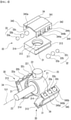
- a tripod constant-velocity joint according to an embodiment of the present invention includes an outer joint member 10 and an inner joint member 20.
- the outer joint member 10 has a longitudinal axis OLA and is provided with a center cavity 11 and three roller tracks 12. One side of the outer joint member 10 is open to make the center cavity 11 exposed to the outside, and the other side thereof may be connected to a shaft for power transmission.
- the center cavity 11 may approximately have a cylindrical shape
- the roller track 12 may have a shape of a recess indented in a radially outward direction from the center cavity 11 and may be elongated in a longitudinal direction.
- the three roller tracks 12 may be equidistantly disposed along a circumferential direction.
- the inner joint member 20 is disposed within the center cavity 11 of the outer joint member 10.
- the inner joint member 20 includes a center body 21 and three journals 22 which are protruded in a radially outward direction from the center body 21. At this time, as shown in FIG. 2 , the three journals 22 may be equidistantly disposed along a circumferential direction and are respectively disposed within the roller track 12 of the outer joint member 10.
- a shaft 23 is connected to the center body 21, and the shaft 23 has a longitudinal axis ILA.
- the shaft 23 may be connected to the center body 21 so as to rotate therewith, and for example may be splined with the center body 21.
- roller assemblies 30 are respectively coupled to the three journals 22. As shown in FIG. 1 and FIG. 2 , the roller assembly 30 is disposed within the roller track 12 of the outer joint member 10 in a state of being coupled to the journal 22 of the inner joint member 20.
- the roller assembly 30 is coupled to the journal 22 such that an articulation of the longitudinal axis ILA of the inner joint member 20 with respect to the longitudinal axis OLA of the outer joint member 10 can be allowed. Furthermore, the roller assembly 30 is disposed in the roller track 12 so as to be movable in a direction parallel with the longitudinal axis OLA of the outer joint member 10 along the roller track 12.
- the respective roller assembly 30 includes an inner race 31, a first ball array 32, a second ball array 33 and a ball cage 34.
- the inner race 31 is connected to the journal 22.
- the inner race 31 may have an overall hexahedral shape and may have a through hole 311 formed in a center axis JA of the journal 22.
- the journal 22 of the inner joint member 20 is inserted into the through hole 311.
- a contact surface 312 forming the through hole 311 of the inner race 31 and an outer circumferential surface 221 of the journal 22 may respectively be formed in a curved surface to allow the inner joint member 20 to be articulated with respect to the inner race 31.
- the outer circumferential surface 221 of the journal 22 may be formed as a curved convex surface, and correspondingly the contact surface 312 forming the through hole 311 of the inner race 31 may be formed as a planar surface. That is, the contact surface 312 of the inner race 31 may have a cylindrical shape. Since the outer circumferential surface 221 of the journal 22 has a curved convex surface and the contact surface 312 forming the through hole 311 of the inner race 31 has a cylindrical shape, a movement of the journal 22 for an articulation of the joint can be ensured.
- first inner ball groove 313 and a second inner ball groove 314 are respectively formed on both lateral sides of the inner race 31.
- the first and the second inner ball grooves 313 and 314 may be respectively elongated approximately in a direction parallel with the longitudinal axis OLA of the outer joint member 10 and may have a sectional shape of a semicircle.
- the first ball array 32 including a plurality of balls 32a, 32b and 32c is disposed in the first inner ball groove 313.
- the second ball array 33 including a plurality of balls 33a, 33b and 33c is disposed in the second inner ball groove 314.
- a ball cage 34 restricts movements of the first ball array 32 and the second ball array 33 in a longitudinal direction.
- the ball cage 34 may include a central portion 341 which elongates approximately in a direction perpendicular to the center axis JA of the journal 22 to face the radially outward surface of the inner race 31, and a first wing portion 342 and a second wing portion 343 which are respectively extended in a radially inward direction from both lateral ends of the central portion 341.
- the ball cage 34 may have a length similar to the inner race 31 in a longitudinal direction of the outer joint member 10.
- the central portion 341 of the ball cage 34 may be formed to be convex in an outward direction so as not to interfere with an outer end portion of the journal 22 of the inner joint member 20, and correspondingly a bottom surface 123 of the roller track 12 may be outwardly indented.
- the first wing portion 342 faces the first inner ball groove 313 and includes a first window array 344 having a plurality of windows 344a, 344b and 344c for respectively receiving the balls 32a, 32b and 32c composing the first ball array 32.
- the second wing portion 343 faces the second inner ball groove 314 and includes a second window array 345 having a plurality of windows 345a, 345b and 345c for respectively receiving the balls 33a, 33b and 33c composing the second ball array 33.
- the respective window may be formed to receive the respective ball, and the ball is received in the window so that the movement thereof in a longitudinal direction is restricted.
- a first outer ball groove 125 and a second outer ball groove 126 which make a pair with the first inner ball groove 313 and the second inner ball groove 314 are respectively formed on both lateral sides of the roller track 12.
- the first and the second outer ball grooves 125 and 126 may be elongated in a direction parallel with the longitudinal axis OLA of the outer joint member 10 so as to face the first and the second inner ball grooves 313 and 314.
- a first ball track 361 is formed by a combination of the first inner ball groove 313 and the first outer ball groove 215 facing one another
- a second ball track 362 is formed by a combination of the second inner ball groove 314 and the second outer ball groove 126 facing one another.
- the first ball array 32 is disposed in the first ball track 361, and the second ball array 33 is disposed in the second ball track 362.
- the balls 32a, 32b and 32c composing the first ball array 32 are disposed in the first ball track 361 in a state of being housed in the ball cage 34, inner portions thereof being disposed within the first inner ball groove 313 and outer portions thereof being disposed within the first outer ball groove 125, and the balls 33a, 33b and 33c composing the second ball array 33 are disposed in the second ball track 362 in a state of being housed in the ball cage 34, inner portions thereof being disposed within the second inner ball groove 314 and outer portions thereof being disposed within the second outer ball groove 126.
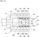
- FIG. 4 shows a non-articulated state
- FIG. 5 shows a state in which the roller assembly relatively moves with respect to the outer joint member in an articulated state.
- the first ball track 361 is formed such that a sectional area thereof becomes larger in a direction toward an open side (right side in FIG. 4 ) of the outer joint member 10, and to the contrary, the second ball track 362 is formed such that a sectional area thereof becomes smaller in a direction toward an open side of the outer joint member 10.
- diameters of the balls 32a, 32b and 32c composing the first ball array 32 become greater in a direction toward an open side of the outer joint member 10
- diameters of the balls 33a, 33b and 33c composing the second ball array 33 become smaller in a direction toward an open side of the outer joint member 10.
- a bottom surface of the first inner ball groove 313 and a bottom surface of the first outer ball groove 125 may be formed to become deeper in a direction toward an open side of the outer joint member 10, and a bottom surface of the second inner ball groove 314 and a bottom surface of the second outer ball groove 126 may be formed to become shallower in a direction toward an open side of the outer joint member 10.
- the first ball track 361 may thereby have a shape of a truncated cone being widened in a direction toward an open side of the outer joint member 10
- the second ball track 362 may have a shape of a truncated cone being narrowed in a direction toward an open side of the outer joint member 10.
- a line CL1 connecting centers of the balls 32a, 32b and 32c composing the first ball array 32 and a line CL2 connecting centers of the balls 33a, 33b and 33c composing the second ball array 33 may be parallel with the longitudinal axis OLA of the outer joint member 10.
- the roller is realized by balls instead of a conventional ring member, an increase of a friction force can be minimized due to geometrical characteristic of a spherical ball even at a large articulation angle.
- kinematic movement in a plunging or in an articulation can be realized. That is, the inner race and the ball are restricted by each other due to these structures, and hereby the balls can be prevented from being separated from the inner race and can be located at a desired region in the inner race.
- the present invention relates to a tripod constant-velocity joint, so it has an industrial applicability.
Landscapes
- Engineering & Computer Science (AREA)
- General Engineering & Computer Science (AREA)
- Mechanical Engineering (AREA)
- Bearings For Parts Moving Linearly (AREA)
- Rolling Contact Bearings (AREA)
- Pivots And Pivotal Connections (AREA)
Claims (5)
- Joint homocinétique à tripode comprenant :un élément formant joint extérieur (10) ayant une cavité (11) allongée dans une direction longitudinale et trois voies de roulement (12) ;un élément formant joint intérieur (20) ayant un corps central (21) et trois paliers (22) se projetant radialement vers l'extérieur depuis le corps central (21) ; ettrois assemblages de roulement (30) respectivement couplés au palier (22) dans un état dans lequel ils sont respectivement disposés dans les voies de roulement (12),dans lequel l'assemblage de roulement (30) respectif comprend :une piste intérieure (31) qui est connectée au palier (22) et qui est dotée d'une première rainure à billes intérieure (313) et d'une seconde rainure à billes intérieure (314) sur les deux côtés latéraux de celle-ci ;un premier agencement de billes (32) et un second agencement de billes (33) ayant respectivement une pluralité de billes (32a, 32b, 32c, 33a, 33b, 33c) qui sont respectivement disposées dans la première rainure à billes intérieure (313) et dans la seconde rainure à billes intérieure (314) ; etune cage à billes (34) qui restreint des déplacements du premier agencement de billes (32) et du second agencement de billes (33) dans une direction longitudinale de celle-ci ;dans lequel le premier agencement de billes (32) est disposé dans une première voie à billes (361) qui est formée par la première rainure à billes intérieure (313) et une première rainure à billes extérieure (125) formée dans une surface latérale correspondante de la voie de roulement (12) et le second agencement de billes (33) est disposé dans une seconde voie à billes (362) qui est formée par la seconde rainure à billes intérieure (314) et une seconde rainure à billes extérieure (126) formée dans une surface latérale correspondante de la voie de roulement (12), et dans lequel la première voie à billes (361) est configurée de telle sorte qu'une aire de section de celle-ci devient plus grande dans une direction vers un côté ouvert de l'élément formant joint extérieur (10) et la seconde voie à billes (362) est configurée de telle sorte qu'une aire de section de celle-ci devient plus petite dans une direction vers le côté ouvert de l'élément formant joint extérieur (10) ;caractérisé en ce quedes diamètres de la pluralité de billes (32a, 32b, 32c) composant le premier agencement de billes (32) deviennent plus grands dans une direction vers le côté ouvert de l'élément formant joint extérieur (10) et des diamètres de la pluralité de billes (33a, 33b, 33c) composant le second agencement de billes (33) deviennent plus petits dans une direction vers le côté ouvert de l'élément formant joint extérieur (10).
- Joint homocinétique à tripode selon la revendication 1, dans lequel la première rainure à billes intérieure (313) est formée de telle sorte qu'une surface de fond de celle-ci devient plus profonde dans une direction vers le côté ouvert de l'élément formant joint extérieur (10) et la seconde rainure à billes intérieure (314) est formée de telle sorte qu'une surface de fond de celle-ci devient moins profonde dans une direction vers le côté ouvert de l'élément formant joint extérieur (10).
- Joint homocinétique à tripode selon la revendication 1 ou 2, dans lequel la première rainure à billes extérieure (125) est formée de telle sorte qu'une surface de fond de celle-ci devient plus profonde dans une direction vers le côté ouvert de l'élément formant joint extérieur (10) et la seconde rainure à billes extérieure (126) est formée de telle sorte qu'une surface de fond de celle-ci devient moins profonde dans une direction vers le côté ouvert de l'élément formant joint extérieur (10).
- Joint homocinétique à tripode selon la revendication 1, dans lequel la première voie à billes (361) a une forme d'un cône tronqué qui est élargi dans une direction vers le côté ouvert de l'élément formant joint extérieur (10) et la seconde voie à billes (362) a une forme d'un cône tronqué qui est rétréci dans une direction vers le côté ouvert de l'élément formant joint extérieur (10).
- Joint homocinétique à tripode selon la revendication 4, dans lequel des lignes centrales (CL1, CL2) de la première voie à billes (361) et de la seconde voie à billes (362) sont respectivement parallèles à une direction longitudinale (OLA) de l'élément formant joint extérieur (10).
Applications Claiming Priority (2)
| Application Number | Priority Date | Filing Date | Title |
|---|---|---|---|
| KR1020160175657A KR101759904B1 (ko) | 2016-12-21 | 2016-12-21 | 트라이포드 등속 조인트 |
| PCT/KR2017/015218 WO2018117679A1 (fr) | 2016-12-21 | 2017-12-21 | Joint homocinétique à tripode |
Publications (3)
| Publication Number | Publication Date |
|---|---|
| EP3546779A1 EP3546779A1 (fr) | 2019-10-02 |
| EP3546779A4 EP3546779A4 (fr) | 2020-11-04 |
| EP3546779B1 true EP3546779B1 (fr) | 2022-03-23 |
Family
ID=59443552
Family Applications (1)
| Application Number | Title | Priority Date | Filing Date |
|---|---|---|---|
| EP17884535.0A Active EP3546779B1 (fr) | 2016-12-21 | 2017-12-21 | Joint homocinétique à tripode |
Country Status (5)
| Country | Link |
|---|---|
| US (1) | US11248657B2 (fr) |
| EP (1) | EP3546779B1 (fr) |
| KR (1) | KR101759904B1 (fr) |
| CN (1) | CN110100108B (fr) |
| WO (1) | WO2018117679A1 (fr) |
Families Citing this family (5)
| Publication number | Priority date | Publication date | Assignee | Title |
|---|---|---|---|---|
| CN115552139B (zh) * | 2020-07-28 | 2025-10-31 | 舍弗勒技术股份两合公司 | 三球销式联轴器和转向机构 |
| KR102361891B1 (ko) * | 2021-03-10 | 2022-02-14 | 이래에이엠에스 주식회사 | 트라이포드 등속 조인트의 트랙 레이스의 제조 방법 |
| KR102346518B1 (ko) * | 2021-03-10 | 2022-01-03 | 이래에이엠에스 주식회사 | 트라이포드 등속 조인트 |
| KR20250023674A (ko) * | 2023-08-10 | 2025-02-18 | 남양넥스모 주식회사 | 차량 조향장치용 인텀 샤프트의 볼리테이너 제조방법 및 그것을 이용하여 제조된 차량 조향장치용 인텀 샤프트의 볼리테이너 |
| KR102741712B1 (ko) * | 2024-03-13 | 2024-12-11 | 이래에이엠에스 주식회사 | 트라이포드 등속조인트 |
Family Cites Families (17)
| Publication number | Priority date | Publication date | Assignee | Title |
|---|---|---|---|---|
| JPS58200814A (ja) * | 1982-05-14 | 1983-11-22 | Nissan Motor Co Ltd | 伸縮自在ドライブシヤフト |
| FR2554528B1 (fr) * | 1983-11-04 | 1987-04-10 | Glaenzer Spicer Sa | Agencement de deux organes animes de mouvements alternatifs relatifs et son application a des joints homocinetiques coulissants |
| FR2580751B1 (fr) * | 1985-04-19 | 1989-12-08 | Glaenzer Spicer Sa | Joint homocinetique coulissant, notamment pour transmission laterale de vehicule |
| FR2628803A2 (fr) * | 1985-04-19 | 1989-09-22 | Glaenzer Spicer Sa | Joint homocinetique coulissant, notamment pour transmission laterale de vehicule |
| US4954120A (en) * | 1988-01-25 | 1990-09-04 | Toyota Jidosha Kabushiki Kaisha | Slidable constant velocity joint |
| DE3905566C1 (de) * | 1989-02-23 | 1990-03-01 | Löhr & Bromkamp GmbH, 6050 Offenbach | Gleichlaufgelenk mit axial gegeneinander verschiebbaren Gelenkteilen |
| DE3936602C2 (de) * | 1989-11-03 | 1994-10-27 | Loehr & Bromkamp Gmbh | Tripodegelenk |
| EP0524955A4 (en) | 1990-04-16 | 1993-07-21 | Gkn Automotive, Inc. | A telescopic triplan universal joint |
| FR2729194B1 (fr) * | 1995-01-11 | 1997-04-04 | Gkn Glaenzer Spicer | Joint de transmission coulissant, notamment pour vehicule automobile |
| MY125713A (en) | 1997-02-10 | 2006-08-30 | Honda Motor Co Ltd | Constant velocity universal joint |
| JPH1182532A (ja) | 1997-09-03 | 1999-03-26 | Honda Motor Co Ltd | 等速ジョイント |
| WO2003036115A1 (fr) | 2001-10-26 | 2003-05-01 | Ntn Corporation | Joint tripode |
| JP2003130080A (ja) * | 2001-10-26 | 2003-05-08 | Ntn Corp | トリポード型等速自在継手 |
| KR100741308B1 (ko) | 2005-12-27 | 2007-07-23 | 한국프랜지공업 주식회사 | 트라이포드 등속조인트 구조 및 롤러어셈블리의 조립방법 |
| JP2008039036A (ja) | 2006-08-04 | 2008-02-21 | Jtekt Corp | トリポード型等速ジョイント |
| DE102007023354B4 (de) * | 2007-05-18 | 2009-10-01 | Gkn Driveline Deutschland Gmbh | Kugelgleichlaufverschiebegelenk mit geringen Verschiebekräften |
| EP2297488B1 (fr) * | 2008-06-27 | 2013-01-02 | GKN Driveline International GmbH | Soufflet ayant une première région d'attache déplacée dans le sens axial |
-
2016
- 2016-12-21 KR KR1020160175657A patent/KR101759904B1/ko active Active
-
2017
- 2017-12-21 US US16/471,682 patent/US11248657B2/en active Active
- 2017-12-21 WO PCT/KR2017/015218 patent/WO2018117679A1/fr not_active Ceased
- 2017-12-21 CN CN201780079835.2A patent/CN110100108B/zh active Active
- 2017-12-21 EP EP17884535.0A patent/EP3546779B1/fr active Active
Also Published As
| Publication number | Publication date |
|---|---|
| WO2018117679A1 (fr) | 2018-06-28 |
| US20190390718A1 (en) | 2019-12-26 |
| US11248657B2 (en) | 2022-02-15 |
| CN110100108A (zh) | 2019-08-06 |
| EP3546779A1 (fr) | 2019-10-02 |
| EP3546779A4 (fr) | 2020-11-04 |
| CN110100108B (zh) | 2021-06-29 |
| KR101759904B1 (ko) | 2017-07-20 |
Similar Documents
| Publication | Publication Date | Title |
|---|---|---|
| EP3546779A1 (fr) | Joint homocinétique à tripode | |
| KR101024883B1 (ko) | 트리포드형 등속 조인트 | |
| JP4920465B2 (ja) | 摺動式等速ジョイント | |
| US7407441B2 (en) | Constant velocity joint | |
| US20250327484A1 (en) | Tripod constant velocity joint | |
| EP1394430B1 (fr) | Accouplement croise | |
| US20160356317A1 (en) | Constant-velocity joint | |
| EP2831437B1 (fr) | Joint homocinétique | |
| US20110212789A1 (en) | Fixed constant velocity universal joint | |
| US8684850B2 (en) | Constant velocity universal joint | |
| JP4681235B2 (ja) | 等速ジョイント | |
| CN110345170B (zh) | 等速接头 | |
| US11047425B2 (en) | Stationary constant-velocity universal joint | |
| US10364849B2 (en) | Constant-velocity joint | |
| US11248660B2 (en) | Constant velocity joint | |
| CN107120358B (zh) | 等速万向节 | |
| JP6711747B2 (ja) | 固定式等速自在継手 | |
| CN111188845B (zh) | 等速万向接头 | |
| EP1942285B1 (fr) | Joint homocinetique compose | |
| JP6287877B2 (ja) | 等速ジョイント | |
| JP2006017143A (ja) | 等速ジョイント | |
| JP7071854B2 (ja) | 等速自在継手 | |
| WO2026058629A1 (fr) | Joint homocinétique de type tripode | |
| US11073179B2 (en) | Sliding-type constant velocity universal joint and method for manufacturing same | |
| WO2025187210A1 (fr) | Joint tripode homocinétique universel |
Legal Events
| Date | Code | Title | Description |
|---|---|---|---|
| STAA | Information on the status of an ep patent application or granted ep patent |
Free format text: STATUS: THE INTERNATIONAL PUBLICATION HAS BEEN MADE |
|
| PUAI | Public reference made under article 153(3) epc to a published international application that has entered the european phase |
Free format text: ORIGINAL CODE: 0009012 |
|
| STAA | Information on the status of an ep patent application or granted ep patent |
Free format text: STATUS: REQUEST FOR EXAMINATION WAS MADE |
|
| 17P | Request for examination filed |
Effective date: 20190626 |
|
| AK | Designated contracting states |
Kind code of ref document: A1 Designated state(s): AL AT BE BG CH CY CZ DE DK EE ES FI FR GB GR HR HU IE IS IT LI LT LU LV MC MK MT NL NO PL PT RO RS SE SI SK SM TR |
|
| AX | Request for extension of the european patent |
Extension state: BA ME |
|
| DAV | Request for validation of the european patent (deleted) | ||
| DAX | Request for extension of the european patent (deleted) | ||
| A4 | Supplementary search report drawn up and despatched |
Effective date: 20201002 |
|
| RIC1 | Information provided on ipc code assigned before grant |
Ipc: F16D 3/223 20110101ALI20200928BHEP Ipc: F16D 3/205 20060101AFI20200928BHEP |
|
| GRAP | Despatch of communication of intention to grant a patent |
Free format text: ORIGINAL CODE: EPIDOSNIGR1 |
|
| STAA | Information on the status of an ep patent application or granted ep patent |
Free format text: STATUS: GRANT OF PATENT IS INTENDED |
|
| INTG | Intention to grant announced |
Effective date: 20211102 |
|
| GRAS | Grant fee paid |
Free format text: ORIGINAL CODE: EPIDOSNIGR3 |
|
| GRAA | (expected) grant |
Free format text: ORIGINAL CODE: 0009210 |
|
| STAA | Information on the status of an ep patent application or granted ep patent |
Free format text: STATUS: THE PATENT HAS BEEN GRANTED |
|
| AK | Designated contracting states |
Kind code of ref document: B1 Designated state(s): AL AT BE BG CH CY CZ DE DK EE ES FI FR GB GR HR HU IE IS IT LI LT LU LV MC MK MT NL NO PL PT RO RS SE SI SK SM TR |
|
| REG | Reference to a national code |
Ref country code: GB Ref legal event code: FG4D |
|
| REG | Reference to a national code |
Ref country code: CH Ref legal event code: EP |
|
| REG | Reference to a national code |
Ref country code: IE Ref legal event code: FG4D |
|
| REG | Reference to a national code |
Ref country code: DE Ref legal event code: R096 Ref document number: 602017055064 Country of ref document: DE |
|
| REG | Reference to a national code |
Ref country code: AT Ref legal event code: REF Ref document number: 1477630 Country of ref document: AT Kind code of ref document: T Effective date: 20220415 |
|
| REG | Reference to a national code |
Ref country code: LT Ref legal event code: MG9D |
|
| REG | Reference to a national code |
Ref country code: NL Ref legal event code: MP Effective date: 20220323 |
|
| PG25 | Lapsed in a contracting state [announced via postgrant information from national office to epo] |
Ref country code: SE Free format text: LAPSE BECAUSE OF FAILURE TO SUBMIT A TRANSLATION OF THE DESCRIPTION OR TO PAY THE FEE WITHIN THE PRESCRIBED TIME-LIMIT Effective date: 20220323 Ref country code: RS Free format text: LAPSE BECAUSE OF FAILURE TO SUBMIT A TRANSLATION OF THE DESCRIPTION OR TO PAY THE FEE WITHIN THE PRESCRIBED TIME-LIMIT Effective date: 20220323 Ref country code: NO Free format text: LAPSE BECAUSE OF FAILURE TO SUBMIT A TRANSLATION OF THE DESCRIPTION OR TO PAY THE FEE WITHIN THE PRESCRIBED TIME-LIMIT Effective date: 20220623 Ref country code: LT Free format text: LAPSE BECAUSE OF FAILURE TO SUBMIT A TRANSLATION OF THE DESCRIPTION OR TO PAY THE FEE WITHIN THE PRESCRIBED TIME-LIMIT Effective date: 20220323 Ref country code: HR Free format text: LAPSE BECAUSE OF FAILURE TO SUBMIT A TRANSLATION OF THE DESCRIPTION OR TO PAY THE FEE WITHIN THE PRESCRIBED TIME-LIMIT Effective date: 20220323 Ref country code: BG Free format text: LAPSE BECAUSE OF FAILURE TO SUBMIT A TRANSLATION OF THE DESCRIPTION OR TO PAY THE FEE WITHIN THE PRESCRIBED TIME-LIMIT Effective date: 20220623 |
|
| REG | Reference to a national code |
Ref country code: AT Ref legal event code: MK05 Ref document number: 1477630 Country of ref document: AT Kind code of ref document: T Effective date: 20220323 |
|
| PG25 | Lapsed in a contracting state [announced via postgrant information from national office to epo] |
Ref country code: LV Free format text: LAPSE BECAUSE OF FAILURE TO SUBMIT A TRANSLATION OF THE DESCRIPTION OR TO PAY THE FEE WITHIN THE PRESCRIBED TIME-LIMIT Effective date: 20220323 Ref country code: GR Free format text: LAPSE BECAUSE OF FAILURE TO SUBMIT A TRANSLATION OF THE DESCRIPTION OR TO PAY THE FEE WITHIN THE PRESCRIBED TIME-LIMIT Effective date: 20220624 Ref country code: FI Free format text: LAPSE BECAUSE OF FAILURE TO SUBMIT A TRANSLATION OF THE DESCRIPTION OR TO PAY THE FEE WITHIN THE PRESCRIBED TIME-LIMIT Effective date: 20220323 |
|
| PG25 | Lapsed in a contracting state [announced via postgrant information from national office to epo] |
Ref country code: NL Free format text: LAPSE BECAUSE OF FAILURE TO SUBMIT A TRANSLATION OF THE DESCRIPTION OR TO PAY THE FEE WITHIN THE PRESCRIBED TIME-LIMIT Effective date: 20220323 |
|
| PG25 | Lapsed in a contracting state [announced via postgrant information from national office to epo] |
Ref country code: SM Free format text: LAPSE BECAUSE OF FAILURE TO SUBMIT A TRANSLATION OF THE DESCRIPTION OR TO PAY THE FEE WITHIN THE PRESCRIBED TIME-LIMIT Effective date: 20220323 Ref country code: SK Free format text: LAPSE BECAUSE OF FAILURE TO SUBMIT A TRANSLATION OF THE DESCRIPTION OR TO PAY THE FEE WITHIN THE PRESCRIBED TIME-LIMIT Effective date: 20220323 Ref country code: RO Free format text: LAPSE BECAUSE OF FAILURE TO SUBMIT A TRANSLATION OF THE DESCRIPTION OR TO PAY THE FEE WITHIN THE PRESCRIBED TIME-LIMIT Effective date: 20220323 Ref country code: PT Free format text: LAPSE BECAUSE OF FAILURE TO SUBMIT A TRANSLATION OF THE DESCRIPTION OR TO PAY THE FEE WITHIN THE PRESCRIBED TIME-LIMIT Effective date: 20220725 Ref country code: ES Free format text: LAPSE BECAUSE OF FAILURE TO SUBMIT A TRANSLATION OF THE DESCRIPTION OR TO PAY THE FEE WITHIN THE PRESCRIBED TIME-LIMIT Effective date: 20220323 Ref country code: EE Free format text: LAPSE BECAUSE OF FAILURE TO SUBMIT A TRANSLATION OF THE DESCRIPTION OR TO PAY THE FEE WITHIN THE PRESCRIBED TIME-LIMIT Effective date: 20220323 Ref country code: CZ Free format text: LAPSE BECAUSE OF FAILURE TO SUBMIT A TRANSLATION OF THE DESCRIPTION OR TO PAY THE FEE WITHIN THE PRESCRIBED TIME-LIMIT Effective date: 20220323 Ref country code: AT Free format text: LAPSE BECAUSE OF FAILURE TO SUBMIT A TRANSLATION OF THE DESCRIPTION OR TO PAY THE FEE WITHIN THE PRESCRIBED TIME-LIMIT Effective date: 20220323 |
|
| PG25 | Lapsed in a contracting state [announced via postgrant information from national office to epo] |
Ref country code: PL Free format text: LAPSE BECAUSE OF FAILURE TO SUBMIT A TRANSLATION OF THE DESCRIPTION OR TO PAY THE FEE WITHIN THE PRESCRIBED TIME-LIMIT Effective date: 20220323 Ref country code: IS Free format text: LAPSE BECAUSE OF FAILURE TO SUBMIT A TRANSLATION OF THE DESCRIPTION OR TO PAY THE FEE WITHIN THE PRESCRIBED TIME-LIMIT Effective date: 20220723 Ref country code: AL Free format text: LAPSE BECAUSE OF FAILURE TO SUBMIT A TRANSLATION OF THE DESCRIPTION OR TO PAY THE FEE WITHIN THE PRESCRIBED TIME-LIMIT Effective date: 20220323 |
|
| REG | Reference to a national code |
Ref country code: DE Ref legal event code: R097 Ref document number: 602017055064 Country of ref document: DE |
|
| PLBE | No opposition filed within time limit |
Free format text: ORIGINAL CODE: 0009261 |
|
| STAA | Information on the status of an ep patent application or granted ep patent |
Free format text: STATUS: NO OPPOSITION FILED WITHIN TIME LIMIT |
|
| PG25 | Lapsed in a contracting state [announced via postgrant information from national office to epo] |
Ref country code: DK Free format text: LAPSE BECAUSE OF FAILURE TO SUBMIT A TRANSLATION OF THE DESCRIPTION OR TO PAY THE FEE WITHIN THE PRESCRIBED TIME-LIMIT Effective date: 20220323 |
|
| 26N | No opposition filed |
Effective date: 20230102 |
|
| PG25 | Lapsed in a contracting state [announced via postgrant information from national office to epo] |
Ref country code: SI Free format text: LAPSE BECAUSE OF FAILURE TO SUBMIT A TRANSLATION OF THE DESCRIPTION OR TO PAY THE FEE WITHIN THE PRESCRIBED TIME-LIMIT Effective date: 20220323 |
|
| REG | Reference to a national code |
Ref country code: CH Ref legal event code: PL |
|
| REG | Reference to a national code |
Ref country code: BE Ref legal event code: MM Effective date: 20221231 |
|
| PG25 | Lapsed in a contracting state [announced via postgrant information from national office to epo] |
Ref country code: LU Free format text: LAPSE BECAUSE OF NON-PAYMENT OF DUE FEES Effective date: 20221221 |
|
| PG25 | Lapsed in a contracting state [announced via postgrant information from national office to epo] |
Ref country code: LI Free format text: LAPSE BECAUSE OF NON-PAYMENT OF DUE FEES Effective date: 20221231 Ref country code: IE Free format text: LAPSE BECAUSE OF NON-PAYMENT OF DUE FEES Effective date: 20221221 Ref country code: CH Free format text: LAPSE BECAUSE OF NON-PAYMENT OF DUE FEES Effective date: 20221231 |
|
| PG25 | Lapsed in a contracting state [announced via postgrant information from national office to epo] |
Ref country code: BE Free format text: LAPSE BECAUSE OF NON-PAYMENT OF DUE FEES Effective date: 20221231 |
|
| PG25 | Lapsed in a contracting state [announced via postgrant information from national office to epo] |
Ref country code: HU Free format text: LAPSE BECAUSE OF FAILURE TO SUBMIT A TRANSLATION OF THE DESCRIPTION OR TO PAY THE FEE WITHIN THE PRESCRIBED TIME-LIMIT; INVALID AB INITIO Effective date: 20171221 |
|
| PG25 | Lapsed in a contracting state [announced via postgrant information from national office to epo] |
Ref country code: CY Free format text: LAPSE BECAUSE OF FAILURE TO SUBMIT A TRANSLATION OF THE DESCRIPTION OR TO PAY THE FEE WITHIN THE PRESCRIBED TIME-LIMIT Effective date: 20220323 |
|
| PG25 | Lapsed in a contracting state [announced via postgrant information from national office to epo] |
Ref country code: MK Free format text: LAPSE BECAUSE OF FAILURE TO SUBMIT A TRANSLATION OF THE DESCRIPTION OR TO PAY THE FEE WITHIN THE PRESCRIBED TIME-LIMIT Effective date: 20220323 |
|
| PG25 | Lapsed in a contracting state [announced via postgrant information from national office to epo] |
Ref country code: MC Free format text: LAPSE BECAUSE OF FAILURE TO SUBMIT A TRANSLATION OF THE DESCRIPTION OR TO PAY THE FEE WITHIN THE PRESCRIBED TIME-LIMIT Effective date: 20220323 |
|
| PG25 | Lapsed in a contracting state [announced via postgrant information from national office to epo] |
Ref country code: TR Free format text: LAPSE BECAUSE OF FAILURE TO SUBMIT A TRANSLATION OF THE DESCRIPTION OR TO PAY THE FEE WITHIN THE PRESCRIBED TIME-LIMIT Effective date: 20220323 Ref country code: MC Free format text: LAPSE BECAUSE OF FAILURE TO SUBMIT A TRANSLATION OF THE DESCRIPTION OR TO PAY THE FEE WITHIN THE PRESCRIBED TIME-LIMIT Effective date: 20220323 |
|
| PG25 | Lapsed in a contracting state [announced via postgrant information from national office to epo] |
Ref country code: MT Free format text: LAPSE BECAUSE OF FAILURE TO SUBMIT A TRANSLATION OF THE DESCRIPTION OR TO PAY THE FEE WITHIN THE PRESCRIBED TIME-LIMIT Effective date: 20220323 |
|
| REG | Reference to a national code |
Ref country code: DE Ref legal event code: R081 Ref document number: 602017055064 Country of ref document: DE Owner name: HANSAE MOBILITY CO., LTD., DAEGU, KR Free format text: FORMER OWNER: ERAE AMS CO., LTD., DAEGU, KR |
|
| PGFP | Annual fee paid to national office [announced via postgrant information from national office to epo] |
Ref country code: DE Payment date: 20250930 Year of fee payment: 9 |
|
| PGFP | Annual fee paid to national office [announced via postgrant information from national office to epo] |
Ref country code: GB Payment date: 20251001 Year of fee payment: 9 |
|
| PGFP | Annual fee paid to national office [announced via postgrant information from national office to epo] |
Ref country code: IT Payment date: 20251121 Year of fee payment: 9 |
|
| PGFP | Annual fee paid to national office [announced via postgrant information from national office to epo] |
Ref country code: FR Payment date: 20251008 Year of fee payment: 9 |