EP3546788B1 - Ressort pneumatique - Google Patents
Ressort pneumatique Download PDFInfo
- Publication number
- EP3546788B1 EP3546788B1 EP19164938.3A EP19164938A EP3546788B1 EP 3546788 B1 EP3546788 B1 EP 3546788B1 EP 19164938 A EP19164938 A EP 19164938A EP 3546788 B1 EP3546788 B1 EP 3546788B1
- Authority
- EP
- European Patent Office
- Prior art keywords
- chamber
- cylinder
- spring
- pneumatic
- value
- Prior art date
- Legal status (The legal status is an assumption and is not a legal conclusion. Google has not performed a legal analysis and makes no representation as to the accuracy of the status listed.)
- Active
Links
Images


Classifications
-
- F—MECHANICAL ENGINEERING; LIGHTING; HEATING; WEAPONS; BLASTING
- F16—ENGINEERING ELEMENTS AND UNITS; GENERAL MEASURES FOR PRODUCING AND MAINTAINING EFFECTIVE FUNCTIONING OF MACHINES OR INSTALLATIONS; THERMAL INSULATION IN GENERAL
- F16F—SPRINGS; SHOCK-ABSORBERS; MEANS FOR DAMPING VIBRATION
- F16F9/00—Springs, vibration-dampers, shock-absorbers, or similarly-constructed movement-dampers using a fluid or the equivalent as damping medium
- F16F9/02—Springs, vibration-dampers, shock-absorbers, or similarly-constructed movement-dampers using a fluid or the equivalent as damping medium using gas only or vacuum
- F16F9/0209—Telescopic
-
- B—PERFORMING OPERATIONS; TRANSPORTING
- B62—LAND VEHICLES FOR TRAVELLING OTHERWISE THAN ON RAILS
- B62K—CYCLES; CYCLE FRAMES; CYCLE STEERING DEVICES; RIDER-OPERATED TERMINAL CONTROLS SPECIALLY ADAPTED FOR CYCLES; CYCLE AXLE SUSPENSIONS; CYCLE SIDE-CARS, FORECARS, OR THE LIKE
- B62K25/00—Axle suspensions
- B62K25/04—Axle suspensions for mounting axles resiliently on cycle frame or fork
- B62K25/06—Axle suspensions for mounting axles resiliently on cycle frame or fork with telescopic fork, e.g. including auxiliary rocking arms
- B62K25/08—Axle suspensions for mounting axles resiliently on cycle frame or fork with telescopic fork, e.g. including auxiliary rocking arms for front wheel
-
- F—MECHANICAL ENGINEERING; LIGHTING; HEATING; WEAPONS; BLASTING
- F16—ENGINEERING ELEMENTS AND UNITS; GENERAL MEASURES FOR PRODUCING AND MAINTAINING EFFECTIVE FUNCTIONING OF MACHINES OR INSTALLATIONS; THERMAL INSULATION IN GENERAL
- F16F—SPRINGS; SHOCK-ABSORBERS; MEANS FOR DAMPING VIBRATION
- F16F9/00—Springs, vibration-dampers, shock-absorbers, or similarly-constructed movement-dampers using a fluid or the equivalent as damping medium
- F16F9/02—Springs, vibration-dampers, shock-absorbers, or similarly-constructed movement-dampers using a fluid or the equivalent as damping medium using gas only or vacuum
- F16F9/0209—Telescopic
- F16F9/0236—Telescopic characterised by having a hollow piston rod
-
- F—MECHANICAL ENGINEERING; LIGHTING; HEATING; WEAPONS; BLASTING
- F16—ENGINEERING ELEMENTS AND UNITS; GENERAL MEASURES FOR PRODUCING AND MAINTAINING EFFECTIVE FUNCTIONING OF MACHINES OR INSTALLATIONS; THERMAL INSULATION IN GENERAL
- F16F—SPRINGS; SHOCK-ABSORBERS; MEANS FOR DAMPING VIBRATION
- F16F9/00—Springs, vibration-dampers, shock-absorbers, or similarly-constructed movement-dampers using a fluid or the equivalent as damping medium
- F16F9/06—Springs, vibration-dampers, shock-absorbers, or similarly-constructed movement-dampers using a fluid or the equivalent as damping medium using both gas and liquid
- F16F9/062—Bi-tubular units
-
- F—MECHANICAL ENGINEERING; LIGHTING; HEATING; WEAPONS; BLASTING
- F16—ENGINEERING ELEMENTS AND UNITS; GENERAL MEASURES FOR PRODUCING AND MAINTAINING EFFECTIVE FUNCTIONING OF MACHINES OR INSTALLATIONS; THERMAL INSULATION IN GENERAL
- F16F—SPRINGS; SHOCK-ABSORBERS; MEANS FOR DAMPING VIBRATION
- F16F9/00—Springs, vibration-dampers, shock-absorbers, or similarly-constructed movement-dampers using a fluid or the equivalent as damping medium
- F16F9/32—Details
- F16F9/44—Means on or in the damper for manual or non-automatic adjustment; such means combined with temperature correction
-
- F—MECHANICAL ENGINEERING; LIGHTING; HEATING; WEAPONS; BLASTING
- F16—ENGINEERING ELEMENTS AND UNITS; GENERAL MEASURES FOR PRODUCING AND MAINTAINING EFFECTIVE FUNCTIONING OF MACHINES OR INSTALLATIONS; THERMAL INSULATION IN GENERAL
- F16F—SPRINGS; SHOCK-ABSORBERS; MEANS FOR DAMPING VIBRATION
- F16F9/00—Springs, vibration-dampers, shock-absorbers, or similarly-constructed movement-dampers using a fluid or the equivalent as damping medium
- F16F9/003—Dampers characterised by having pressure absorbing means other than gas, e.g. sponge rubber
Definitions
- the invention generally relates to a pneumatic spring and in particular to a pneumatic spring for forks or shock absorbers of vehicles such as bicycles or motorcycles.
- pneumatic springs are those elements which elastically connect two points, and which are generally comprised of a compression chamber engaged with a first point, such as the frame of a vehicle, and a piston slidable inside the compression chamber, engaged with a second point, such as the wheel hub of a vehicle.
- the air, or pneumatic, spring is therefore, to sum up, a device comprised of a pressurized air chamber delimited by a piston which, moving along its axis, decreases the volume of this chamber. This causes the piston, when pushed, to produce an increase in pressure inside the chamber, thereby creating a force that pushes the piston back to its initial position.
- the average elastic ratio of the spring is lower than the one under the adiabatic condition, and moreover, as speed increases, when the condition becomes adiabatic, there is a decrease in the hysteresis of the spring in the stroke / pressure cycle exerted on the piston by the air.
- a pneumatic suspension which is provided with a positive chamber and a negative chamber connected by a bypass channel and also provided with an elastic volume compensator arranged in the positive chamber which, in combination with the bypass channel, tends to make the behaviour of the suspension more linear, the initial pressure being equal, i.e. to reduce the elastic coefficient of the suspension at the end of stroke.
- US9662951 a method for protecting the suspension and frame of a vehicle is disclosed, the method including the use of a dumper with a piston member sliding in a cylinder where a resilient shock absorbing member is placed.
- US 2013 105 260 A1 discloses all the technical features of the preamble of appended claim 1, and the corresponding technical features of appended claim 8.
- the object of the present invention is therefore to propose a pneumatic spring for suspensions, which, the elastic support provided at the end of stroke being equal, is capable of ensuring greater support during the compression of the suspension, without the need to raise the base value of the pressure in the cylinder.
- a further object is to propose a pneumatic spring for suspensions, which overcomes the aforementioned drawbacks of the systems of the known type by reducing the increase in the elastic hysteresis of the spring as speeds increase, and thus making the hysteresis more constant and the pneumatic suspension more similar in its behaviour to a spring suspension, while keeping the advantages of the air spring, such as lightness and the possibility of easily changing the elastic ratio and the volume in the compression chamber.
- Yet another object is to allow to modify the compression ratio of the suspension, while keeping the entire compression stroke available.
- a pneumatic spring comprising a closed-cell elastomer body arranged so as to be free inside a compression chamber of the spring.
- a first advantage is that, as the pressure in the compression chamber changes, the closed-cell structure of the elastomer determines a substantially elastic deformation associated with a viscous behaviour, sensitive in the spring expansion and elongation stage, due to the nature of the material itself.
- a further advantage of the invention is that the behaviour of the suspension is improved in the case of terrains characterized by small roughness, since in the final compression cycles there is a reduction of the elastic springback force and therefore a greater adhesion of the wheel to the ground, due to the fact that in the elongation stage of the suspension the elastomer body tends to expand more slowly compared to the contraction speed experienced in the compression stroke, and therefore reduces the decrease in the elastic hysteresis of the suspension at high speeds.
- a further advantage is that the available volume of the compression chamber remains substantially unchanged.
- a further advantage in the case of suspensions of cycles or motorcycles, is that the driver will benefit from good support at lower speeds or on less rough routes, but at the same time he will not have to suffer an increase in sudden nervousness when he will have to drive round tracks with impacts on obstacles at high speed, taking advantage from the constancy of the force provided by the suspension.
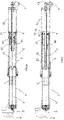
- a pneumatic spring for vehicle suspensions comprising a compression chamber 1 placed within a cylinder 2 provided with a first external attachment point 4, is described.
- the cylinder 2 is provided with a first valve 9 for injecting pressurized air into the chamber 1 and obtaining a resting pre-charge value of the chamber 1.
- the points 4, 6 are associated with a point in a wheel, such as the hub, and a point of the frame, such as a fork.
- the piston 3 can therefore move between a resting configuration of the spring, wherein the internal pressure of the chamber 1 has a first value p1, and at least one compressed configuration of the spring corresponding to an approaching of the first and the second attachment points 4, 6 compared to the resting configuration, wherein the internal pressure of the chamber 1 assumes a second value p2, greater than said first value p1.
- a closed-cell expanded elastomer body 7 is arranged inside the compression chamber 1, so as to be free, i.e. without any fixed engagement with other elements, being thus free to move inside the compression chamber and to contract elastically as the pressure in the chamber 1 increases ( fig.1b ), and to return to the initial conformation ( fig.1a ) as the pressure decreases.
- the free elastomer body does not interact mechanically with any other solid part apart from being contained within the chamber in which it is inserted, thereby interacting only with the air or gas particles, which cause it to compress and expand depending on the pneumatic pressure.
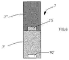
- the elastomer body 7 has a cylindrical or hollow cylindrical shape, possibly made of several modular parts and also of different materials, for example parts made of closed-cell elastomer with different mechanical characteristics and / or non-deformable rigid parts.
- the body 7 can be made of the material POR 303/B RS marketed by Eurofoam Srl, an expanded elastomer with CR/NEOPRENE-based closed-cell cellular structure and a density of 160kg/m3.
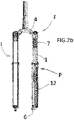
- the spring of the invention can advantageously be used as a pneumatic spring in a pneumatic fork F for bicycles or motorcycles ( Figs. 2, 2a , 2b ) comprising a hydraulic section with viscous behaviour I, of the type known per se, schematised in Fig.2b , and a hydraulic section comprising a spring according to the invention and further provided with elastic means which are opposed to the elastic behaviour of the spring.
- the cylinder 2 is mounted so as to be telescopically slidable with respect to an additional cylinder 11.
- the cylinder 2 slides with respect to the outer cylinder 11 or "leg” by means of a seal 35 mounted on a ring 37 which has an additional seal 36 resting on the outer surface of the stem 5.
- the cylinder 11 is also integral with the second attachment point 6 of the stem 5, and the piston 3 is arranged in an intermediate position inside the cylinder 2 between the first compression chamber 1, referred to as a positive chamber, and a second compression chamber 12, referred to as a negative chamber, which has an opposing behaviour with respect to the positive chamber 1
- the internal pressure of the negative chamber 12 has a first value p3 at the resting configuration of the spring and assumes a second value p4 greater than said first value p3 in an extended configuration of the spring corresponding to a spacing of the first and second attachment points 4, 6 compared to the resting configuration.
- the fork F comprises a second valve 14 which can be accessed externally and communicates with the second compression chamber 12 via a cavity 15 and a hole 13 of the stem 5 to introduce pressurized air into said second chamber 12 and obtain a resting pre-charge value of the pressure of the chamber 12.
- the fork F may comprise an end-of-stroke block 16 arranged within the second compression chamber 12.
- Fig. 2a illustrates a further embodiment (known per se) of a fork provided with the spring of the invention.
- the ring 37 is not provided with seals with respect to the stem 5 and the cylinder 11, the chamber 12 does not act as a negative chamber, and its opposing effect with respect to the pneumatic spring is exerted by a helical spring 38, (compressed in the configuration of Fig. 2a ) fixed to a bushing 39 integral with the stem 5 and abutting the ring 37.
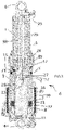
- the spring of the invention can be used in a shock absorber A for bicycles or motorcycles, illustrated schematically in Figure 3 .
- the shock absorber A comprises a hydraulic cartridge 15 provided with a hydraulic cylinder 16 filled with a viscous fluid and connected to a first of the attachment points 4, 6, and a hydraulic piston 17 connected by means of a stem 18 to the second attachment point 4, 6 and slidable in said hydraulic cylinder 16 between two sections 20, 21 of the cylinder 16 separated by a fluid passage 23, so that, in response to a movement consisting of moving away or approaching the points 4, 6, the piston moves in the cylinder and the fluid is forced to pass through the passage 23 by resisting the mutual movement of the attachment points 4, 6.
- the shock absorber A comprises a valve 19 for adjusting the fluid flow through the passage 23, comprised of, for example, a rod 26 with a conical end 27 facing the passage 23 and connected to an adjustment knob 25 accessible externally by the shock absorber so as to be moved away from or approached to the passage and, therefore, to open or close the available clearance of the passage itself.
- the stem 5 of the pneumatic piston 3 has the shape of a hollow cylinder inside which the hydraulic cylinder 16 can slide and which forms part of the compression chamber 1.
- the stem 5 slides sealingly with respect to the cylinder 2 by means of a further outer gasket 28 mounted on the cylinder 2 so that the pneumatic piston 3 is included between the chamber 1, acting as a positive chamber, and a section 12 of the cylinder 2 comprised between the piston 3 and the gasket 28, acting as a negative compression chamber.
- a flange 42 fixed to a spring 41 (compressed in Fig. 3 ) placed in abutment of a ring 43 and acting, in operation, as a negative spring opposing the compression chamber 1, is also mounted on the stem 18
- the shock absorber A may be provided with a hydraulic compensating chamber 29, which in the described example is arranged concentrically to the cylinder 2 and comprises a membrane 30 comprised between a first region 31, filled with viscous fluid and communicating through conduits 33 with chamber 20 of the cylinder 16, and a second region 32, for example filled with pressurized gas, and the containment wall of the compensating chamber.
- the membrane 30 is capable of expanding elastically as the pressure of the fluid in the region 31 increases, receiving a back pressure from the gas region 32, the amount of which will depend on the pre-charge pressure of the region 32 itself applied through a valve 40 communicating with the region 32.
- the cylinder 2 has an end with an closure 8 that can be opened for inserting and/or replacing the body 7 in the chamber 1, and/or for inserting into the cylinder 2 a further rigid volume reducing body 10, of the type known per se and used to raise the end-of-stroke elastic support force of a pneumatic spring.
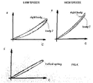
- Figure 4 illustrates schematically the trend of the stroke/elastic return force elastic deformation cycle, which represents the elastic hysteresis of a spring according to the invention.
- Fig. 4 represents the hysteresis which occurs in the elastic cycle of the pneumatic spring of the invention with the elastomer body 7 (cycle of the Elastic force F/stroke C curve of the piston) provided with a rigid volume spacer (at operating pressures), measured both at low speeds and at high speeds compared to that of a steel helical spring (the hysteresis of the steel springs does not vary with the compression speed).
- the chart shows that at high speeds the reduction of the elastic hysteresis of the spring of the invention is less than that of the conventional spring, i.e. the pneumatic spring provided with the body 7 tends to have a more regular elastic hysteresis, similar to that of the helical spring, which does not vary with the speed of the stroke, thus being more predictable and regular.
- Fig.5 shows charts which qualitatively represent the trend of the F/C elastic curve in the following cases:
- Figure 5b shows the trends of the same deformation force curves, represented in the case of a fork provided with a positive chamber and a negative chamber (or negative spring) wherein, therefore, as the initial pressure in the compression chamber changes, the initial value of the elastic force provided by the fork remains the balance value between the two chambers.
- the invention has important advantages, since the closed-cell elastomer body 7 allows to modify the elastic curve of the spring thus obtaining greater flexibility and allowing the user to adapt the response of the suspension to its own sensitivity and to the characteristics of the terrain.
- the invention allows several parts 7', 7" to be combined modularly, for example through interlocking portions 70', 70, possibly made of different materials to exploit different elastic properties of the selected materials
- the present invention has been described according to preferred embodiments; however, equivalent variants can be conceived without departing from the scope of the present invention.
Landscapes
- Engineering & Computer Science (AREA)
- General Engineering & Computer Science (AREA)
- Mechanical Engineering (AREA)
- Fluid-Damping Devices (AREA)
- Axle Suspensions And Sidecars For Cycles (AREA)
- Springs (AREA)
Claims (8)
- Amortisseur de chocs pour bicyclettes ou motocyclettes comprenant une cartouche hydraulique (15) pourvue de :un cylindre hydraulique (16) rempli d'un fluide visqueux et relié à un premier point de raccordement externe (4),un piston hydraulique (17) relié par une tige (18) à un second point de raccordement (6) et pouvant coulisser dans ledit cylindre hydraulique (16),un passage de fluide (23) pour faire passer une quantité de fluide visqueux depuis une première section (20) jusqu'à une seconde section (21) du cylindre hydraulique (16) en réponse et en résistance opposée à un mouvement de va-et-vient desdits points de raccordement (4, 6),l'amortisseur de chocs comprenant en outre un ressort pneumatique pour des suspensions de véhicule incluant :au moins une chambre de compression (1) à l'intérieur du cylindre de ressort pneumatique (2) pourvue dudit premier point de raccordement externe (4),un piston pneumatique coulissant (3) avec un joint de pression dans la chambre et relié à une tige (5) pourvue dudit second point de raccordement (6) à l'extérieur du cylindre (2),dans lequel ledit ressort pneumatique comprend un corps élastomère à cellules fermées (7) agencé à l'intérieur de la chambre de compression (1), ledit piston (3) étant apte à se déplacer entre une configuration de repos du ressort dans laquelle la pression interne de la chambre (1) a une première valeur (p1) et au moins une configuration de ressort compressé correspondant à une approche des premier et second points de raccordement (4, 6) par rapport à la configuration de repos dans laquelle la pression interne de la chambre (1) prend une seconde valeur (p2) supérieure à ladite première valeur (p1), dans lequel, en réponse à ladite seconde valeur (p2), ledit corps élastomère (7) adopte une configuration contractée élastiquement déformée, et revient à la configuration de repos au fur et à mesure que la pression diminue, en présentant une déformation sensiblement élastique associée à un comportement visqueux, caractérisé en ce que ledit corps élastomère (7) est libre de se déplacer à l'intérieur de la chambre de compression (1).
- Amortisseur de chocs selon la revendication 1, dans lequel ledit cylindre de ressort pneumatique (2) a une extrémité avec une fermeture (8) qui peut être ouverte pour une insertion et/ou un remplacement dudit corps élastomère (7) dans la chambre (1).
- Amortisseur de chocs selon l'une des revendications précédentes, dans lequel ledit cylindre de ressort pneumatique (2) est pourvu d'une première vanne (9) pour l'introduction d'air pressurisé dans la chambre (1).
- Amortisseur de chocs selon l'une des revendications précédentes, dans lequel ledit corps élastomère (7) est de forme cylindrique creuse.
- Amortisseur de chocs selon l'une des revendications précédentes, dans lequel ledit corps élastomère (7) comprend plusieurs parties modulaires (7', 7").
- Amortisseur de chocs selon la revendication 5, dans lequel lesdites parties modulaires sont constituées de matériaux différents.
- Amortisseur de chocs selon la revendication 1, comprenant une chambre hydraulique de compensation (29) pourvue d'une membrane (30) comprise entre une première région (31) communiquant à travers des conduits (33) avec la chambre (20) du cylindre (16) et une seconde région (32) remplie de gaz pressurisé.
- Fourche pneumatique pour bicyclettes ou motocyclettes comportant une section hydraulique (I) avec un comportement visqueux et une section pneumatique (P) comprenant un ressort pneumatique pour des suspensions de véhicule incluant :au moins une chambre de compression (1) à l'intérieur d'un cylindre de ressort pneumatique (2) pourvu d'un premier point de raccordement externe (4),un piston pneumatique coulissant (3) avec un joint de pression dans la chambre et relié à une tige (5) pourvue d'un second point de raccordement (6) à l'extérieur du cylindre de ressort pneumatique (2),un corps élastomère à cellules fermées (7) agencé à l'intérieur de la chambre de compression (1),ledit piston (3) étant apte à se déplacer entre une configuration de repos du ressort dans laquelle la pression interne de la chambre (1) a une première valeur (p1) et au moins une configuration de ressort compressé correspondant à une approche des premier et second points de raccordement (4, 6) par rapport à la configuration de repos dans laquelle la pression interne de la chambre (1) prend une seconde valeur (p2) supérieure à ladite première valeur (p1), dans laquelle, en réponse à ladite seconde valeur (p2), ledit corps élastomère (7) adopte une configuration contractée élastiquement déformée, et revient à la configuration de repos au fur et à mesure que la pression diminue, en présentant une déformation sensiblement élastique associée à un comportement visqueux,ledit corps élastomère (7) étant libre de se déplacer à l'intérieur de la chambre de compression (1),dans laquelle ledit cylindre de ressort pneumatique (2) est monté en coulissement télescopique par rapport à un autre cylindre (11) solidaire du second point de raccordement (6) de la tige (5), et dans lequel ledit piston (3) est agencé à une position intermédiaire à l'intérieur du cylindre de ressort pneumatique (2) entre ladite première chambre de compression (1) et une seconde chambre (12) pourvue de moyens élastiques qui sont opposés au comportement élastique du ressort.
Applications Claiming Priority (1)
| Application Number | Priority Date | Filing Date | Title |
|---|---|---|---|
| IT102018000003955A IT201800003955A1 (it) | 2018-03-26 | 2018-03-26 | Molla pneumatica |
Publications (2)
| Publication Number | Publication Date |
|---|---|
| EP3546788A1 EP3546788A1 (fr) | 2019-10-02 |
| EP3546788B1 true EP3546788B1 (fr) | 2022-04-27 |
Family
ID=62597938
Family Applications (1)
| Application Number | Title | Priority Date | Filing Date |
|---|---|---|---|
| EP19164938.3A Active EP3546788B1 (fr) | 2018-03-26 | 2019-03-25 | Ressort pneumatique |
Country Status (3)
| Country | Link |
|---|---|
| EP (1) | EP3546788B1 (fr) |
| ES (1) | ES2918253T3 (fr) |
| IT (1) | IT201800003955A1 (fr) |
Cited By (1)
| Publication number | Priority date | Publication date | Assignee | Title |
|---|---|---|---|---|
| EP4332408A1 (fr) * | 2022-07-06 | 2024-03-06 | Giant Manufactoring Co., Ltd. | Structure d'amortisseur de choc de bicyclette et bicyclette |
Families Citing this family (1)
| Publication number | Priority date | Publication date | Assignee | Title |
|---|---|---|---|---|
| GB202117442D0 (en) * | 2021-12-02 | 2022-01-19 | Carbon Air Ltd | Air spring |
Family Cites Families (6)
| Publication number | Priority date | Publication date | Assignee | Title |
|---|---|---|---|---|
| US3587789A (en) * | 1968-02-28 | 1971-06-28 | Bilstein August | Hydropneumatic single-cylinder shock absorber |
| BE1012681A6 (fr) * | 1999-05-20 | 2001-02-06 | Wille Jean Joseph Armand Arnol | Systeme de suspension, procede d'amortissement et element de locomotion. |
| US8123006B1 (en) * | 2007-04-13 | 2012-02-28 | Hayes Bicycle Group, Inc. | Lightweight gas spring design with volume compensator incorporated into a suspension fork for two wheeled vehicles |
| JP5159249B2 (ja) * | 2007-10-30 | 2013-03-06 | ヤマハ発動機株式会社 | 車両 |
| DE102011053127A1 (de) * | 2011-08-30 | 2013-02-28 | B-Labs Ag | Feder-Dämpfervorrichtung für ein Fahrrad |
| US9662951B1 (en) * | 2016-01-06 | 2017-05-30 | Caterpillar Inc. | Truck strut fail-safe |
-
2018
- 2018-03-26 IT IT102018000003955A patent/IT201800003955A1/it unknown
-
2019
- 2019-03-25 ES ES19164938T patent/ES2918253T3/es active Active
- 2019-03-25 EP EP19164938.3A patent/EP3546788B1/fr active Active
Cited By (2)
| Publication number | Priority date | Publication date | Assignee | Title |
|---|---|---|---|---|
| EP4332408A1 (fr) * | 2022-07-06 | 2024-03-06 | Giant Manufactoring Co., Ltd. | Structure d'amortisseur de choc de bicyclette et bicyclette |
| US12576944B2 (en) | 2022-07-06 | 2026-03-17 | Giant Manufacturing Co., Ltd. | Bicycle shock absorber structure and bicycle |
Also Published As
| Publication number | Publication date |
|---|---|
| ES2918253T3 (es) | 2022-07-14 |
| EP3546788A1 (fr) | 2019-10-02 |
| IT201800003955A1 (it) | 2019-09-26 |
Similar Documents
| Publication | Publication Date | Title |
|---|---|---|
| US20240309929A1 (en) | Suspension system | |
| US7124865B2 (en) | Pressure regulating dampers | |
| US9688347B2 (en) | Vehicle suspension damper | |
| US6837343B1 (en) | Shock absorber | |
| KR101518097B1 (ko) | 유공압 서스펜션 유닛 | |
| US6213261B1 (en) | Hydropneumatic spring | |
| EP3546788B1 (fr) | Ressort pneumatique | |
| US12331806B2 (en) | Telescopic passive damper | |
| CN109563848B (zh) | 悬挂系统 | |
| JP2017166573A (ja) | 緩衝器 | |
| US20060163017A1 (en) | Hollow rod monotube shock absorber | |
| JPH0669476U (ja) | 油圧緩衝器のピストンチェックバルブ構造 | |
| JP4296015B2 (ja) | フロントフォーク | |
| EP4170195B1 (fr) | Amortisseur télescopique passif | |
| JP5719254B2 (ja) | 単筒型緩衝器 | |
| JP4839093B2 (ja) | 減衰装置 | |
| AU2003208121B2 (en) | Shock Absorber | |
| JP2018054020A (ja) | ショックアブソーバ |
Legal Events
| Date | Code | Title | Description |
|---|---|---|---|
| PUAI | Public reference made under article 153(3) epc to a published international application that has entered the european phase |
Free format text: ORIGINAL CODE: 0009012 |
|
| STAA | Information on the status of an ep patent application or granted ep patent |
Free format text: STATUS: THE APPLICATION HAS BEEN PUBLISHED |
|
| AK | Designated contracting states |
Kind code of ref document: A1 Designated state(s): AL AT BE BG CH CY CZ DE DK EE ES FI FR GB GR HR HU IE IS IT LI LT LU LV MC MK MT NL NO PL PT RO RS SE SI SK SM TR |
|
| AX | Request for extension of the european patent |
Extension state: BA ME |
|
| STAA | Information on the status of an ep patent application or granted ep patent |
Free format text: STATUS: REQUEST FOR EXAMINATION WAS MADE |
|
| 17P | Request for examination filed |
Effective date: 20191230 |
|
| RBV | Designated contracting states (corrected) |
Designated state(s): AL AT BE BG CH CY CZ DE DK EE ES FI FR GB GR HR HU IE IS IT LI LT LU LV MC MK MT NL NO PL PT RO RS SE SI SK SM TR |
|
| STAA | Information on the status of an ep patent application or granted ep patent |
Free format text: STATUS: EXAMINATION IS IN PROGRESS |
|
| 17Q | First examination report despatched |
Effective date: 20201130 |
|
| GRAP | Despatch of communication of intention to grant a patent |
Free format text: ORIGINAL CODE: EPIDOSNIGR1 |
|
| STAA | Information on the status of an ep patent application or granted ep patent |
Free format text: STATUS: GRANT OF PATENT IS INTENDED |
|
| INTG | Intention to grant announced |
Effective date: 20220111 |
|
| GRAS | Grant fee paid |
Free format text: ORIGINAL CODE: EPIDOSNIGR3 |
|
| GRAA | (expected) grant |
Free format text: ORIGINAL CODE: 0009210 |
|
| STAA | Information on the status of an ep patent application or granted ep patent |
Free format text: STATUS: THE PATENT HAS BEEN GRANTED |
|
| AK | Designated contracting states |
Kind code of ref document: B1 Designated state(s): AL AT BE BG CH CY CZ DE DK EE ES FI FR GB GR HR HU IE IS IT LI LT LU LV MC MK MT NL NO PL PT RO RS SE SI SK SM TR |
|
| REG | Reference to a national code |
Ref country code: GB Ref legal event code: FG4D |
|
| REG | Reference to a national code |
Ref country code: CH Ref legal event code: EP |
|
| REG | Reference to a national code |
Ref country code: AT Ref legal event code: REF Ref document number: 1487148 Country of ref document: AT Kind code of ref document: T Effective date: 20220515 |
|
| REG | Reference to a national code |
Ref country code: DE Ref legal event code: R096 Ref document number: 602019014026 Country of ref document: DE |
|
| REG | Reference to a national code |
Ref country code: IE Ref legal event code: FG4D |
|
| REG | Reference to a national code |
Ref country code: ES Ref legal event code: FG2A Ref document number: 2918253 Country of ref document: ES Kind code of ref document: T3 Effective date: 20220714 |
|
| REG | Reference to a national code |
Ref country code: LT Ref legal event code: MG9D |
|
| REG | Reference to a national code |
Ref country code: NL Ref legal event code: MP Effective date: 20220427 |
|
| REG | Reference to a national code |
Ref country code: AT Ref legal event code: MK05 Ref document number: 1487148 Country of ref document: AT Kind code of ref document: T Effective date: 20220427 |
|
| PG25 | Lapsed in a contracting state [announced via postgrant information from national office to epo] |
Ref country code: NL Free format text: LAPSE BECAUSE OF FAILURE TO SUBMIT A TRANSLATION OF THE DESCRIPTION OR TO PAY THE FEE WITHIN THE PRESCRIBED TIME-LIMIT Effective date: 20220427 |
|
| PG25 | Lapsed in a contracting state [announced via postgrant information from national office to epo] |
Ref country code: SE Free format text: LAPSE BECAUSE OF FAILURE TO SUBMIT A TRANSLATION OF THE DESCRIPTION OR TO PAY THE FEE WITHIN THE PRESCRIBED TIME-LIMIT Effective date: 20220427 Ref country code: PT Free format text: LAPSE BECAUSE OF FAILURE TO SUBMIT A TRANSLATION OF THE DESCRIPTION OR TO PAY THE FEE WITHIN THE PRESCRIBED TIME-LIMIT Effective date: 20220829 Ref country code: NO Free format text: LAPSE BECAUSE OF FAILURE TO SUBMIT A TRANSLATION OF THE DESCRIPTION OR TO PAY THE FEE WITHIN THE PRESCRIBED TIME-LIMIT Effective date: 20220727 Ref country code: LT Free format text: LAPSE BECAUSE OF FAILURE TO SUBMIT A TRANSLATION OF THE DESCRIPTION OR TO PAY THE FEE WITHIN THE PRESCRIBED TIME-LIMIT Effective date: 20220427 Ref country code: HR Free format text: LAPSE BECAUSE OF FAILURE TO SUBMIT A TRANSLATION OF THE DESCRIPTION OR TO PAY THE FEE WITHIN THE PRESCRIBED TIME-LIMIT Effective date: 20220427 Ref country code: GR Free format text: LAPSE BECAUSE OF FAILURE TO SUBMIT A TRANSLATION OF THE DESCRIPTION OR TO PAY THE FEE WITHIN THE PRESCRIBED TIME-LIMIT Effective date: 20220728 Ref country code: FI Free format text: LAPSE BECAUSE OF FAILURE TO SUBMIT A TRANSLATION OF THE DESCRIPTION OR TO PAY THE FEE WITHIN THE PRESCRIBED TIME-LIMIT Effective date: 20220427 Ref country code: BG Free format text: LAPSE BECAUSE OF FAILURE TO SUBMIT A TRANSLATION OF THE DESCRIPTION OR TO PAY THE FEE WITHIN THE PRESCRIBED TIME-LIMIT Effective date: 20220727 Ref country code: AT Free format text: LAPSE BECAUSE OF FAILURE TO SUBMIT A TRANSLATION OF THE DESCRIPTION OR TO PAY THE FEE WITHIN THE PRESCRIBED TIME-LIMIT Effective date: 20220427 |
|
| PG25 | Lapsed in a contracting state [announced via postgrant information from national office to epo] |
Ref country code: RS Free format text: LAPSE BECAUSE OF FAILURE TO SUBMIT A TRANSLATION OF THE DESCRIPTION OR TO PAY THE FEE WITHIN THE PRESCRIBED TIME-LIMIT Effective date: 20220427 Ref country code: PL Free format text: LAPSE BECAUSE OF FAILURE TO SUBMIT A TRANSLATION OF THE DESCRIPTION OR TO PAY THE FEE WITHIN THE PRESCRIBED TIME-LIMIT Effective date: 20220427 Ref country code: LV Free format text: LAPSE BECAUSE OF FAILURE TO SUBMIT A TRANSLATION OF THE DESCRIPTION OR TO PAY THE FEE WITHIN THE PRESCRIBED TIME-LIMIT Effective date: 20220427 Ref country code: IS Free format text: LAPSE BECAUSE OF FAILURE TO SUBMIT A TRANSLATION OF THE DESCRIPTION OR TO PAY THE FEE WITHIN THE PRESCRIBED TIME-LIMIT Effective date: 20220827 |
|
| REG | Reference to a national code |
Ref country code: DE Ref legal event code: R097 Ref document number: 602019014026 Country of ref document: DE |
|
| PG25 | Lapsed in a contracting state [announced via postgrant information from national office to epo] |
Ref country code: SM Free format text: LAPSE BECAUSE OF FAILURE TO SUBMIT A TRANSLATION OF THE DESCRIPTION OR TO PAY THE FEE WITHIN THE PRESCRIBED TIME-LIMIT Effective date: 20220427 Ref country code: SK Free format text: LAPSE BECAUSE OF FAILURE TO SUBMIT A TRANSLATION OF THE DESCRIPTION OR TO PAY THE FEE WITHIN THE PRESCRIBED TIME-LIMIT Effective date: 20220427 Ref country code: RO Free format text: LAPSE BECAUSE OF FAILURE TO SUBMIT A TRANSLATION OF THE DESCRIPTION OR TO PAY THE FEE WITHIN THE PRESCRIBED TIME-LIMIT Effective date: 20220427 Ref country code: EE Free format text: LAPSE BECAUSE OF FAILURE TO SUBMIT A TRANSLATION OF THE DESCRIPTION OR TO PAY THE FEE WITHIN THE PRESCRIBED TIME-LIMIT Effective date: 20220427 Ref country code: DK Free format text: LAPSE BECAUSE OF FAILURE TO SUBMIT A TRANSLATION OF THE DESCRIPTION OR TO PAY THE FEE WITHIN THE PRESCRIBED TIME-LIMIT Effective date: 20220427 Ref country code: CZ Free format text: LAPSE BECAUSE OF FAILURE TO SUBMIT A TRANSLATION OF THE DESCRIPTION OR TO PAY THE FEE WITHIN THE PRESCRIBED TIME-LIMIT Effective date: 20220427 |
|
| PLBE | No opposition filed within time limit |
Free format text: ORIGINAL CODE: 0009261 |
|
| STAA | Information on the status of an ep patent application or granted ep patent |
Free format text: STATUS: NO OPPOSITION FILED WITHIN TIME LIMIT |
|
| PG25 | Lapsed in a contracting state [announced via postgrant information from national office to epo] |
Ref country code: AL Free format text: LAPSE BECAUSE OF FAILURE TO SUBMIT A TRANSLATION OF THE DESCRIPTION OR TO PAY THE FEE WITHIN THE PRESCRIBED TIME-LIMIT Effective date: 20220427 |
|
| 26N | No opposition filed |
Effective date: 20230130 |
|
| PG25 | Lapsed in a contracting state [announced via postgrant information from national office to epo] |
Ref country code: SI Free format text: LAPSE BECAUSE OF FAILURE TO SUBMIT A TRANSLATION OF THE DESCRIPTION OR TO PAY THE FEE WITHIN THE PRESCRIBED TIME-LIMIT Effective date: 20220427 |
|
| REG | Reference to a national code |
Ref country code: DE Ref legal event code: R081 Ref document number: 602019014026 Country of ref document: DE Owner name: FORMULA SRL, IT Free format text: FORMER OWNER: FORMULA S.A.S. DI "FORMULA GROUP S.R.L." & C., PRATO, PO, IT |
|
| P01 | Opt-out of the competence of the unified patent court (upc) registered |
Effective date: 20230529 |
|
| PG25 | Lapsed in a contracting state [announced via postgrant information from national office to epo] |
Ref country code: MC Free format text: LAPSE BECAUSE OF FAILURE TO SUBMIT A TRANSLATION OF THE DESCRIPTION OR TO PAY THE FEE WITHIN THE PRESCRIBED TIME-LIMIT Effective date: 20220427 |
|
| REG | Reference to a national code |
Ref country code: CH Ref legal event code: PL |
|
| REG | Reference to a national code |
Ref country code: BE Ref legal event code: MM Effective date: 20230331 |
|
| PG25 | Lapsed in a contracting state [announced via postgrant information from national office to epo] |
Ref country code: LU Free format text: LAPSE BECAUSE OF NON-PAYMENT OF DUE FEES Effective date: 20230325 |
|
| REG | Reference to a national code |
Ref country code: IE Ref legal event code: MM4A |
|
| PG25 | Lapsed in a contracting state [announced via postgrant information from national office to epo] |
Ref country code: LI Free format text: LAPSE BECAUSE OF NON-PAYMENT OF DUE FEES Effective date: 20230331 Ref country code: IE Free format text: LAPSE BECAUSE OF NON-PAYMENT OF DUE FEES Effective date: 20230325 Ref country code: CH Free format text: LAPSE BECAUSE OF NON-PAYMENT OF DUE FEES Effective date: 20230331 |
|
| PG25 | Lapsed in a contracting state [announced via postgrant information from national office to epo] |
Ref country code: BE Free format text: LAPSE BECAUSE OF NON-PAYMENT OF DUE FEES Effective date: 20230331 |
|
| REG | Reference to a national code |
Ref country code: ES Ref legal event code: PC2A Owner name: FORMULA SRL Effective date: 20240531 |
|
| PG25 | Lapsed in a contracting state [announced via postgrant information from national office to epo] |
Ref country code: BG Free format text: LAPSE BECAUSE OF FAILURE TO SUBMIT A TRANSLATION OF THE DESCRIPTION OR TO PAY THE FEE WITHIN THE PRESCRIBED TIME-LIMIT Effective date: 20220427 |
|
| PG25 | Lapsed in a contracting state [announced via postgrant information from national office to epo] |
Ref country code: BG Free format text: LAPSE BECAUSE OF FAILURE TO SUBMIT A TRANSLATION OF THE DESCRIPTION OR TO PAY THE FEE WITHIN THE PRESCRIBED TIME-LIMIT Effective date: 20220427 |
|
| PGFP | Annual fee paid to national office [announced via postgrant information from national office to epo] |
Ref country code: DE Payment date: 20250331 Year of fee payment: 7 |
|
| PGFP | Annual fee paid to national office [announced via postgrant information from national office to epo] |
Ref country code: ES Payment date: 20250401 Year of fee payment: 7 |
|
| PG25 | Lapsed in a contracting state [announced via postgrant information from national office to epo] |
Ref country code: CY Free format text: LAPSE BECAUSE OF FAILURE TO SUBMIT A TRANSLATION OF THE DESCRIPTION OR TO PAY THE FEE WITHIN THE PRESCRIBED TIME-LIMIT; INVALID AB INITIO Effective date: 20190325 |
|
| PG25 | Lapsed in a contracting state [announced via postgrant information from national office to epo] |
Ref country code: HU Free format text: LAPSE BECAUSE OF FAILURE TO SUBMIT A TRANSLATION OF THE DESCRIPTION OR TO PAY THE FEE WITHIN THE PRESCRIBED TIME-LIMIT; INVALID AB INITIO Effective date: 20190325 |
|
| PG25 | Lapsed in a contracting state [announced via postgrant information from national office to epo] |
Ref country code: TR Free format text: LAPSE BECAUSE OF FAILURE TO SUBMIT A TRANSLATION OF THE DESCRIPTION OR TO PAY THE FEE WITHIN THE PRESCRIBED TIME-LIMIT Effective date: 20220427 |
|
| PGFP | Annual fee paid to national office [announced via postgrant information from national office to epo] |
Ref country code: GB Payment date: 20260330 Year of fee payment: 8 |
|
| PGFP | Annual fee paid to national office [announced via postgrant information from national office to epo] |
Ref country code: IT Payment date: 20260225 Year of fee payment: 8 |
|
| PGFP | Annual fee paid to national office [announced via postgrant information from national office to epo] |
Ref country code: FR Payment date: 20260330 Year of fee payment: 8 |