EP3546807A1 - Soupape comportant un ensemble de guidage de ressort segmenté - Google Patents
Soupape comportant un ensemble de guidage de ressort segmenté Download PDFInfo
- Publication number
- EP3546807A1 EP3546807A1 EP19154255.4A EP19154255A EP3546807A1 EP 3546807 A1 EP3546807 A1 EP 3546807A1 EP 19154255 A EP19154255 A EP 19154255A EP 3546807 A1 EP3546807 A1 EP 3546807A1
- Authority
- EP
- European Patent Office
- Prior art keywords
- spring
- piston
- spring guide
- stroke axis
- along
- Prior art date
- Legal status (The legal status is an assumption and is not a legal conclusion. Google has not performed a legal analysis and makes no representation as to the accuracy of the status listed.)
- Granted
Links
Images
Classifications
-
- F—MECHANICAL ENGINEERING; LIGHTING; HEATING; WEAPONS; BLASTING
- F16—ENGINEERING ELEMENTS AND UNITS; GENERAL MEASURES FOR PRODUCING AND MAINTAINING EFFECTIVE FUNCTIONING OF MACHINES OR INSTALLATIONS; THERMAL INSULATION IN GENERAL
- F16K—VALVES; TAPS; COCKS; ACTUATING-FLOATS; DEVICES FOR VENTING OR AERATING
- F16K24/00—Devices, e.g. valves, for venting or aerating enclosures
-
- F—MECHANICAL ENGINEERING; LIGHTING; HEATING; WEAPONS; BLASTING
- F16—ENGINEERING ELEMENTS AND UNITS; GENERAL MEASURES FOR PRODUCING AND MAINTAINING EFFECTIVE FUNCTIONING OF MACHINES OR INSTALLATIONS; THERMAL INSULATION IN GENERAL
- F16K—VALVES; TAPS; COCKS; ACTUATING-FLOATS; DEVICES FOR VENTING OR AERATING
- F16K15/00—Check valves
- F16K15/02—Check valves with guided rigid valve members
- F16K15/06—Check valves with guided rigid valve members with guided stems
- F16K15/063—Check valves with guided rigid valve members with guided stems the valve being loaded by a spring
- F16K15/066—Check valves with guided rigid valve members with guided stems the valve being loaded by a spring with a plurality of valve members
-
- F—MECHANICAL ENGINEERING; LIGHTING; HEATING; WEAPONS; BLASTING
- F02—COMBUSTION ENGINES; HOT-GAS OR COMBUSTION-PRODUCT ENGINE PLANTS
- F02C—GAS-TURBINE PLANTS; AIR INTAKES FOR JET-PROPULSION PLANTS; CONTROLLING FUEL SUPPLY IN AIR-BREATHING JET-PROPULSION PLANTS
- F02C9/00—Controlling gas-turbine plants; Controlling fuel supply in air- breathing jet-propulsion plants
- F02C9/16—Control of working fluid flow
- F02C9/18—Control of working fluid flow by bleeding, bypassing or acting on variable working fluid interconnections between turbines or compressors or their stages
-
- F—MECHANICAL ENGINEERING; LIGHTING; HEATING; WEAPONS; BLASTING
- F16—ENGINEERING ELEMENTS AND UNITS; GENERAL MEASURES FOR PRODUCING AND MAINTAINING EFFECTIVE FUNCTIONING OF MACHINES OR INSTALLATIONS; THERMAL INSULATION IN GENERAL
- F16K—VALVES; TAPS; COCKS; ACTUATING-FLOATS; DEVICES FOR VENTING OR AERATING
- F16K17/00—Safety valves; Equalising valves, e.g. pressure relief valves
- F16K17/20—Excess-flow valves
-
- F—MECHANICAL ENGINEERING; LIGHTING; HEATING; WEAPONS; BLASTING
- F16—ENGINEERING ELEMENTS AND UNITS; GENERAL MEASURES FOR PRODUCING AND MAINTAINING EFFECTIVE FUNCTIONING OF MACHINES OR INSTALLATIONS; THERMAL INSULATION IN GENERAL
- F16K—VALVES; TAPS; COCKS; ACTUATING-FLOATS; DEVICES FOR VENTING OR AERATING
- F16K31/00—Actuating devices; Operating means; Releasing devices
- F16K31/12—Actuating devices; Operating means; Releasing devices actuated by fluid
- F16K31/122—Actuating devices; Operating means; Releasing devices actuated by fluid the fluid acting on a piston
- F16K31/1221—Actuating devices; Operating means; Releasing devices actuated by fluid the fluid acting on a piston one side of the piston being spring-loaded
-
- F—MECHANICAL ENGINEERING; LIGHTING; HEATING; WEAPONS; BLASTING
- F05—INDEXING SCHEMES RELATING TO ENGINES OR PUMPS IN VARIOUS SUBCLASSES OF CLASSES F01-F04
- F05D—INDEXING SCHEME FOR ASPECTS RELATING TO NON-POSITIVE-DISPLACEMENT MACHINES OR ENGINES, GAS-TURBINES OR JET-PROPULSION PLANTS
- F05D2220/00—Application
- F05D2220/30—Application in turbines
- F05D2220/32—Application in turbines in gas turbines
- F05D2220/323—Application in turbines in gas turbines for aircraft propulsion, e.g. jet engines
-
- F—MECHANICAL ENGINEERING; LIGHTING; HEATING; WEAPONS; BLASTING
- F16—ENGINEERING ELEMENTS AND UNITS; GENERAL MEASURES FOR PRODUCING AND MAINTAINING EFFECTIVE FUNCTIONING OF MACHINES OR INSTALLATIONS; THERMAL INSULATION IN GENERAL
- F16K—VALVES; TAPS; COCKS; ACTUATING-FLOATS; DEVICES FOR VENTING OR AERATING
- F16K24/00—Devices, e.g. valves, for venting or aerating enclosures
- F16K24/02—Devices, e.g. valves, for venting or aerating enclosures the enclosure being itself a valve, tap, or cock
-
- Y—GENERAL TAGGING OF NEW TECHNOLOGICAL DEVELOPMENTS; GENERAL TAGGING OF CROSS-SECTIONAL TECHNOLOGIES SPANNING OVER SEVERAL SECTIONS OF THE IPC; TECHNICAL SUBJECTS COVERED BY FORMER USPC CROSS-REFERENCE ART COLLECTIONS [XRACs] AND DIGESTS
- Y10—TECHNICAL SUBJECTS COVERED BY FORMER USPC
- Y10T—TECHNICAL SUBJECTS COVERED BY FORMER US CLASSIFICATION
- Y10T137/00—Fluid handling
- Y10T137/7722—Line condition change responsive valves
- Y10T137/7781—With separate connected fluid reactor surface
- Y10T137/7793—With opening bias [e.g., pressure regulator]
- Y10T137/7822—Reactor surface closes chamber
- Y10T137/7828—Valve head on yoke
- Y10T137/7829—Yoke has valve closing bias
-
- Y—GENERAL TAGGING OF NEW TECHNOLOGICAL DEVELOPMENTS; GENERAL TAGGING OF CROSS-SECTIONAL TECHNOLOGIES SPANNING OVER SEVERAL SECTIONS OF THE IPC; TECHNICAL SUBJECTS COVERED BY FORMER USPC CROSS-REFERENCE ART COLLECTIONS [XRACs] AND DIGESTS
- Y10—TECHNICAL SUBJECTS COVERED BY FORMER USPC
- Y10T—TECHNICAL SUBJECTS COVERED BY FORMER US CLASSIFICATION
- Y10T137/00—Fluid handling
- Y10T137/7722—Line condition change responsive valves
- Y10T137/7837—Direct response valves [i.e., check valve type]
- Y10T137/7904—Reciprocating valves
- Y10T137/7922—Spring biased
- Y10T137/7925—Piston-type valves
Definitions
- Exemplary embodiments pertain to the art of passive bleed valves and more specifically to a segmented spring guide for a piston within a pneumatic passive bleed valves assembly.
- Pneumatic passive bleed valves in aircraft engines use springs with varying degrees of success. Such valves include a piston that is held in place by a spring and the motion of the piston causes the spring to compress. With pneumatic passive bleed valves on aircraft engines, a compressed spring may endure high levels of vibration in a low damping medium such as air. A resulting axial resonance may cause high cycle fatigue and wear failures.
- a valve comprising: a piston movable along a piston stroke axis in a first axial direction and an opposing second axial direction, the piston having a first axial end that is a distal end of the piston; and a segmented spring guide assembly configured to engage the distal end of the piston along the piston stroke axis, the segmented spring guide assembly comprising: a first spring guide assembly that extends distally from the piston along the piston stroke axis, the first guide assembly including a first spring that is a first coil spring and a first spring guide for guiding the first spring; a second spring guide assembly that extends distally from the first spring guide assembly along the piston stroke axis, the second spring guide assembly including a second spring that is a second coil spring and a second spring guide for guiding the second spring; and wherein the first spring guide assembly and the second spring guide assembly are movably connected to each other along the piston stroke axis to form the segmented guide spring assembly, and wherein when the piston travels along the piston
- first spring and second spring have a same span along the piston stroke axis.
- the first spring guide includes a first elongated member extending through the first spring, a first distal end of the first spring guide including a first annular lip defining a first spring seat, the second spring guide including a second elongated member extending through the second spring, a second distal end of the second spring guide including a second annular lip defining a second spring seat, and wherein when the piston travels along the piston stroke axis, the first spring engages the piston and the first annular lip and the second spring engages the first annular lip and the second annular lip.
- first annular lip is movable along the piston stroke axis and the second annular lip is fixed along the piston stroke axis.
- a connector extends internally between the first spring guide and the second spring guide to movably connect the first spring guide assembly and the second spring guide assembly.
- the connector has a length that enables the first spring guide and the second spring guide to maintain sliding contact while the piston moves along the piston stroke axis.
- the connector is fixed to one of the first spring guide and the second spring guide and slidingly engages another of the first spring guide and the second spring guide.
- the connector is fixed to the first spring guide and slidingly engages the second spring guide.
- the connector is cylindrical having an outer diameter sized to slidingly engage an inner diameter of the second spring guide.
- first spring guide and the second spring guide have a same span along the piston stroke axis.
- a method of applying a biasing force against a piston in a valve as the piston moves along a piston stroke axis in a first direction and an opposing second direction, the piston having a first axial end that is a distal end of the piston comprising: moving the piston along a piston stroke axis in the first direction and the opposing second direction, wherein while moving the piston along the piston stroke axis: applying a first biasing force in the second direction against the first axial end of the piston from a first spring, and applying a second biasing force in the second direction against the first spring from a second spring.
- the first biasing force is the same as the second biasing force.
- the method includes actuating the valve pneumatically.
- the first biasing force is from a first spring of a segmented spring guide assembly in the valve
- the second biasing force is from a second spring of a segmented spring guide assembly in the valve, the first and second spring being disposed along the piston stroke axis.
- the first spring is a first coil spring
- the second spring is a second coil spring having a same length as the first spring
- the first coil spring is guided by a first spring guide of the segmented spring guide assembly
- the second coil spring is guided by a second spring guide of the segmented spring guide assembly
- the first and second spring guides being disposed along the piston stroke axis and being in sliding engagement while the piston moves in the first direction and the second direction.
- the segmented spring guide assembly includes a connector providing the sliding engagement between the first spring guide and the second spring guide.
- the connector is fixedly connected to the first spring guide and slidingly disposed within the second spring guide.
- the method while moving the piston along the piston stroke axis, includes the first spring continuously engaging the piston and a first annular lip on the first spring guide, and the second spring continuously engaging the first annular lip and a second annular lip on the second spring guide.
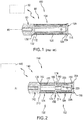
- valve 80 is illustrated schematically and a portion of a valve 80 according to the prior art is also shown in greater detail.
- the valve 80 could be a pneumatic valve such as an air or other fluid valve for use in an aircraft engine.
- the valve 80 includes a piston 90 that has a piston stroke axis A0. As illustrated, only a distal end of the piston 90 is shown.
- the valve 80 also includes a prior art spring guide assembly 100 which includes spring guide 108 and a spring 104.
- the spring guide 108 may include a proximate end 112, a distal end 116 and an elongated cylindrical member 120 extending therebetween.
- the cylindrical member 120 may be surrounded by the spring 104.
- the distal end 116 of the spring guide 108 may include an annular lip 124 defining a distal spring seat.
- the annular lip 124 may be fixed to and contact the spring 104.
- a proximate end 132 of the spring 104 contacts a proximate spring seat 136 in the piston 90.
- the spring guide 108 may be alternatively disposed against and spaced from the piston 90.
- the spring 104 When the spring guide 108 is against the piston 90, the spring 104 is in a compressed state and when the spring guide 104 is spaced from the piston 90, the spring 104 is in an expanded state.
- the spring 104 may have an associated natural frequency that may be excited due to external forces acting on the system at a similar frequency. In operation, the spring 104 is typically compressed in the valve 80 and endures high levels of vibration in a low damping medium such as air. Resulting axial resonance may cause high cycle fatigue and wear failures. Shifting the resonance frequency away from critical driving frequencies may reduce cycle fatigue.
- valve 140 is illustrated schematically and a portion of the valve 140 according to a disclosed embodiment is also shown in greater detail.
- the valve 140 could be a pneumatic valve such as an air or other fluid valve for use in an aircraft engine.
- the valve 140 includes a segmented spring guide 148.
- the valve 140 includes a piston 142 having a piston stroke axis A1.
- the piston 142 may operationally engage with the segmented spring guide assembly 148, which extends distally from the piston 142 along the piston stroke axis A1.
- the segmented spring guide assembly 148 may include a plurality of spring guide assemblies, including a first spring guide assembly 150 and a second spring guide assembly 152, adjacently disposed along the piston stroke axis A1.
- the first spring guide assembly 150 may include a first spring 154 which is a first coil spring guided by a first spring guide 158 which may be a first elongated spring guide.
- the piston stroke axis A1 may be the center axis for the first spring 154 and the first spring guide 158.
- the first spring guide 158 may include a first proximate end 162, a first distal end 166 and a first cylindrical member 170 extending therebetween.
- the first cylindrical member 170 may be a first elongated cylindrical member surrounded by the first spring 154.
- the first distal end 166 of the first spring guide 158 may include a first annular lip 174 defining a first distal spring seat. Continuously during actuation of the piston 142, the first annular lip 174 may contact a first distal end 178 of the first spring 154.
- the second spring guide assembly 152 may include a second spring 184 which is a second coil spring guided by a second spring guide 188 which may be a second elongated spring guide.
- the piston stroke axis A1 may be the center axis for the second spring 184 and the second spring guide 188.
- the second spring guide 188 may include a second proximate end 192, a second distal end 196 and a second cylindrical member 200 extending therebetween.
- the second cylindrical member 200 may be a second elongated cylindrical member that surrounded by the second spring 184.
- the second distal end 196 of the second spring guide 188 may include a second annular lip 204 defining a second distal spring seat. Continuously during actuation of the piston 142, the second annular lip 204 may contact a second distal end 208 of the second spring 184.
- first proximate end 210 of the first spring 154 may continuously contact the piston 142
- a second proximate end 214 of the second spring 184 may continuously contact the first annular lip 174.
- first proximate end 162 of the first spring guide 158 may be alternatively disposed against and spaced from the piston 142
- the second proximate end 192 of the second spring guide may be alternatively disposed against and spaced from first annular lip 174.
- the first spring 154 when the first spring guide 158 is against the piston 142, the first spring 154 may be in a compressed state. In addition, when the second spring guide 188 is against the first annular lip 174, the second spring may 184 be in a compressed state. On the other hand, when the first spring guide 154 is spaced from the piston 142, the first spring 154 may be in an expanded state and when the second spring guide 188 is spaced from the first annular lip 174, the second spring may be in an expanded state.
- a connector 220 may extend internally between the first spring guide assembly 150 and the second spring guide assembly 152.
- the connector 220 may be cylindrical and extend from the first distal end 166 of the first spring guide 158 into the second proximate end 214 of the second spring guide 188.
- the connector 220 may have a length that enables the first spring guide 158 and second spring guide 188 to maintain contact throughout the piston stroke cycle.
- a segmented spring guide assembly 148 with two spring guide assemblies 150, 152 in the valve 140 enables using two springs 154, 184 having an equivalent spring rate to that of a single spring with a same span along the piston stroke axis A1 (e.g., the two springs 154, 184 collectively have the same spring rate as spring 104 in FIG. 1 ).
- the equivalent spring rate for the combined springs 154, 184 in FIG. 2 may be equal to the spring rate for the spring 104 in FIG. 1 .
- doubling the natural frequency moves resonance away from one or more driving frequencies, which may be critical driving frequencies. Additionally, higher frequencies may be less damaging to engine components with a same input level.
- the spring rate for the application may remain unchanged, while a risk of failure due to axial resonance may be minimized. Fewer failures due to high cycle fatigue and wear may lead to an overall longer average spring life.
Landscapes
- Engineering & Computer Science (AREA)
- General Engineering & Computer Science (AREA)
- Mechanical Engineering (AREA)
- Chemical & Material Sciences (AREA)
- Combustion & Propulsion (AREA)
- Physics & Mathematics (AREA)
- Fluid Mechanics (AREA)
- Springs (AREA)
Applications Claiming Priority (1)
| Application Number | Priority Date | Filing Date | Title |
|---|---|---|---|
| US15/940,262 US10753493B2 (en) | 2018-03-29 | 2018-03-29 | Valve with segmented spring guide assembly |
Publications (2)
| Publication Number | Publication Date |
|---|---|
| EP3546807A1 true EP3546807A1 (fr) | 2019-10-02 |
| EP3546807B1 EP3546807B1 (fr) | 2022-08-03 |
Family
ID=65243425
Family Applications (1)
| Application Number | Title | Priority Date | Filing Date |
|---|---|---|---|
| EP19154255.4A Active EP3546807B1 (fr) | 2018-03-29 | 2019-01-29 | Soupape comportant un ensemble de guidage de ressort segmenté |
Country Status (2)
| Country | Link |
|---|---|
| US (1) | US10753493B2 (fr) |
| EP (1) | EP3546807B1 (fr) |
Cited By (1)
| Publication number | Priority date | Publication date | Assignee | Title |
|---|---|---|---|---|
| US11674452B2 (en) * | 2018-04-27 | 2023-06-13 | Hamilton Sundstrand Corporation | Passive active poppet-type bleed valves |
Families Citing this family (1)
| Publication number | Priority date | Publication date | Assignee | Title |
|---|---|---|---|---|
| GB2605755B (en) * | 2021-02-25 | 2024-04-10 | Jb Valves Ltd | Valve Apparatus |
Citations (4)
| Publication number | Priority date | Publication date | Assignee | Title |
|---|---|---|---|---|
| FR1327130A (fr) * | 1962-04-02 | 1963-05-17 | Utilisation Ration Gaz | Valve pour récipient contenant du gaz sous pression |
| DE202008015498U1 (de) * | 2008-11-21 | 2010-04-08 | Heinrichs, Klaus | Entlüftungsventil mit Ent- und Belüftungsfunktion |
| WO2015195810A2 (fr) * | 2014-06-19 | 2015-12-23 | Fmc Technologies, Inc. | Appareil et procédé de module à réponse rapide hydraulique directe |
| EP3241966A1 (fr) * | 2016-05-02 | 2017-11-08 | ITT Manufacturing Enterprises LLC | Commande de débit d'actionneur ayant système de décharge de pression d'absorption d'énergie |
Family Cites Families (57)
| Publication number | Priority date | Publication date | Assignee | Title |
|---|---|---|---|---|
| US1884548A (en) * | 1927-05-25 | 1932-10-25 | Boynton Alexander | Automatic stage lift flowing apparatus for wells |
| US2056133A (en) * | 1935-11-14 | 1936-09-29 | Edna Brass Mfg Company | Terminal valve |
| US2437631A (en) * | 1945-04-20 | 1948-03-09 | Gen Spring Corp | Support |
| US2872149A (en) * | 1953-04-20 | 1959-02-03 | Infilco Inc | Quick-acting release valve |
| US2702044A (en) * | 1953-11-23 | 1955-02-15 | Albert D Johnston | Automatic supply and exhaust valve |
| US3032061A (en) * | 1957-11-27 | 1962-05-01 | Garrett Corp | Relief valve |
| US3171440A (en) * | 1961-01-04 | 1965-03-02 | Pellegrino E Napolitano | Bleeder valve |
| US3112763A (en) * | 1962-04-12 | 1963-12-03 | Hydraulic Unit Specialities Co | Combined high pressure relief and void control valve |
| GB1226747A (fr) * | 1967-07-25 | 1971-03-31 | ||
| US3503601A (en) * | 1967-10-20 | 1970-03-31 | Associated Spring Corp | Axial springs loaded in parallel |
| US3572678A (en) * | 1968-10-17 | 1971-03-30 | Joseph Jerz Jr | Overload spring structure |
| US3603610A (en) * | 1968-12-20 | 1971-09-07 | Clifford W Mezey | Vehicle suspension apparatus |
| US3604450A (en) * | 1969-01-21 | 1971-09-14 | Fruehauf Corp | Valve construction |
| US4033542A (en) * | 1976-08-11 | 1977-07-05 | J. I. Case Company | Dual spring support |
| DE2711393A1 (de) * | 1977-03-16 | 1978-09-21 | Bosch Gmbh Robert | Kraftstoffeinspritzduese |
| US4133178A (en) * | 1977-04-18 | 1979-01-09 | General Motors Corporation | Quick take-up master cylinder |
| US4210170A (en) * | 1978-02-17 | 1980-07-01 | General Signal Corporation | Anti-cavitation and overload relief valve for a hydraulic system |
| US4237920A (en) * | 1979-01-29 | 1980-12-09 | Torr Vacuum Products, Inc. | Spring loaded plug valve |
| US4365647A (en) * | 1980-02-04 | 1982-12-28 | Sperry Corporation | Power transmission |
| US4354523A (en) * | 1980-11-19 | 1982-10-19 | Acf Industries, Incorporated | Lubricant fitting for a valve |
| US4392507A (en) * | 1981-05-15 | 1983-07-12 | Stant Inc. | Two-stage pressure relief valve |
| US4566635A (en) * | 1983-08-10 | 1986-01-28 | Robert Bosch Gmbh | Fuel injection nozzle for internal combustion engines |
| US4637419A (en) * | 1984-07-09 | 1987-01-20 | Vetco Offshore, Inc. | Subsea control pod valve assembly |
| JPS61149569A (ja) * | 1984-12-21 | 1986-07-08 | Diesel Kiki Co Ltd | 燃料噴射弁 |
| DE3610658A1 (de) * | 1985-11-21 | 1987-05-27 | Bosch Gmbh Robert | Kraftstoff-einspritzduese fuer brennkraftmaschinen |
| US4684067A (en) * | 1986-03-21 | 1987-08-04 | General Motors Corporation | Two-stage, hydraulic-assisted fuel injection nozzle |
| US4872365A (en) * | 1988-06-07 | 1989-10-10 | Teleflex Incorporated | Remote actuator for trip valve |
| DE4005774A1 (de) * | 1990-02-23 | 1991-08-29 | Bosch Gmbh Robert | Kraftstoff-einspritzduese fuer brennkraftmaschinen |
| GB9012288D0 (en) * | 1990-06-01 | 1990-07-18 | Lucas Ind Plc | Fuel injection pump |
| DE4101235C1 (fr) * | 1991-01-17 | 1992-06-04 | Robert Bosch Gmbh, 7000 Stuttgart, De | |
| FR2677929A1 (fr) * | 1991-06-24 | 1992-12-24 | Bianchi Mauro Sa | Procede de suspension pour vehicules utilisant deux raideurs, destinees respectivement a l'obtention d'un bon niveau de confort et d'un bon niveau de comportement. |
| US5211340A (en) * | 1991-08-27 | 1993-05-18 | Zexel Corporation | Fuel injector |
| US5205492A (en) * | 1991-12-16 | 1993-04-27 | Gregory Khinchuk | Fuel injection valve |
| NO175654C (no) * | 1991-12-20 | 1994-11-09 | Kongsberg Automative As | Anordning ved seteventiler til misbrukshindring av törrplateclutcher |
| JP3256753B2 (ja) * | 1993-05-07 | 2002-02-12 | 清原 まさ子 | 制御弁 |
| US5511868A (en) * | 1994-10-12 | 1996-04-30 | Caterpillar Inc. | Booster recoil mechanism for endless track machine |
| US5544688A (en) * | 1994-12-23 | 1996-08-13 | Eaton Corporation | Two stage kneeling valve |
| DE19547423B4 (de) * | 1995-12-19 | 2008-09-18 | Robert Bosch Gmbh | Kraftstoffeinspritzventil für Brennkraftmaschinen |
| DE19907348A1 (de) * | 1999-02-20 | 2000-08-24 | Bosch Gmbh Robert | Kraftstoffeinspritzventil |
| US6443180B1 (en) * | 2001-03-15 | 2002-09-03 | Predator Systems Inc. | Hydraulic line adjustable velocity fuse with damping |
| US6837266B2 (en) * | 2002-03-25 | 2005-01-04 | Permco, Inc. | Remotely actuated multiple pressure direct acting relief valve |
| US6986363B1 (en) * | 2002-04-03 | 2006-01-17 | Hydro-Gear Limited Partnership | Valve assembly for use in a hydraulic component |
| US7320334B1 (en) * | 2002-04-03 | 2008-01-22 | Hydro-Gear Limited Partnership | Valve Assembly |
| US7066199B1 (en) * | 2002-04-03 | 2006-06-27 | Hydro-Gear Limited Partnership | Valve assembly |
| US6964280B1 (en) * | 2002-04-03 | 2005-11-15 | Hydro-Gear Limited Partnership | Valve assembly for use in a hydraulic component |
| US6793194B1 (en) * | 2003-04-29 | 2004-09-21 | Bg Tech Ltd. | Rotary valve actuator |
| US7350774B2 (en) * | 2004-09-07 | 2008-04-01 | Danly Iem, Llc | Long travel, high force combination spring |
| US7392823B2 (en) * | 2004-12-01 | 2008-07-01 | Parker-Hannifin Corporation | Combination valve |
| DE102004061862A1 (de) * | 2004-12-22 | 2006-07-06 | Brueninghaus Hydromatik Gmbh | Druckbegrenzungsventil mit reduzierter Differenzfläche |
| US7744062B2 (en) * | 2007-03-09 | 2010-06-29 | Fisher Controls International Llc | Apparatus to vary effective spring rate for use in diaphragm actuators |
| GB0709906D0 (en) * | 2007-05-23 | 2007-07-04 | Anson Ltd | Valves |
| DK2166424T3 (en) * | 2008-09-19 | 2017-09-18 | Isomatic As | Fluid regulator |
| ITBO20110599A1 (it) * | 2011-10-21 | 2013-04-22 | S T S R L | Valvola oleo-idraulica |
| DE102013212947A1 (de) * | 2013-07-03 | 2015-01-08 | Zf Friedrichshafen Ag | Hydraulische Steuerungseinrichtung für ein Automatikgetriebe |
| US9410633B2 (en) * | 2014-08-25 | 2016-08-09 | Industrias Marrucci Ltda. | Remotely-actuated dual-pressure relief valve |
| US9803777B2 (en) * | 2014-08-27 | 2017-10-31 | Dresser, Inc. | Attenuating device for valve assembly |
| US11193427B2 (en) * | 2018-04-27 | 2021-12-07 | Hamilton Sundstrand Corporation | Passive active poppet-type bleed valves |
-
2018
- 2018-03-29 US US15/940,262 patent/US10753493B2/en active Active
-
2019
- 2019-01-29 EP EP19154255.4A patent/EP3546807B1/fr active Active
Patent Citations (4)
| Publication number | Priority date | Publication date | Assignee | Title |
|---|---|---|---|---|
| FR1327130A (fr) * | 1962-04-02 | 1963-05-17 | Utilisation Ration Gaz | Valve pour récipient contenant du gaz sous pression |
| DE202008015498U1 (de) * | 2008-11-21 | 2010-04-08 | Heinrichs, Klaus | Entlüftungsventil mit Ent- und Belüftungsfunktion |
| WO2015195810A2 (fr) * | 2014-06-19 | 2015-12-23 | Fmc Technologies, Inc. | Appareil et procédé de module à réponse rapide hydraulique directe |
| EP3241966A1 (fr) * | 2016-05-02 | 2017-11-08 | ITT Manufacturing Enterprises LLC | Commande de débit d'actionneur ayant système de décharge de pression d'absorption d'énergie |
Cited By (1)
| Publication number | Priority date | Publication date | Assignee | Title |
|---|---|---|---|---|
| US11674452B2 (en) * | 2018-04-27 | 2023-06-13 | Hamilton Sundstrand Corporation | Passive active poppet-type bleed valves |
Also Published As
| Publication number | Publication date |
|---|---|
| US10753493B2 (en) | 2020-08-25 |
| EP3546807B1 (fr) | 2022-08-03 |
| US20190301624A1 (en) | 2019-10-03 |
Similar Documents
| Publication | Publication Date | Title |
|---|---|---|
| EP3546807B1 (fr) | Soupape comportant un ensemble de guidage de ressort segmenté | |
| DE68920241T2 (de) | Federbelastetes Lager. | |
| EP1903252A1 (fr) | Amortisseur magnétorhéologique | |
| DE60306653T2 (de) | Resonanzanordnung für einen linear oszilierend angetriebenen kompressor | |
| KR101371280B1 (ko) | 코일스프링 내구시험기의 범용 시트 | |
| US20130140117A1 (en) | Valve structure of shock absorber | |
| US20120248670A1 (en) | Shock absorber | |
| EP3158629B1 (fr) | Actionneur linéaire, palier hydraulique et véhicule automobile équipé d'un tel palier hydraulique ou actionneur linéaire | |
| EP2659139A1 (fr) | Mécanisme résonant destiné à des compresseurs linéaires | |
| CN102844584B (zh) | 回弹限位器 | |
| WO2018046196A1 (fr) | Ensemble soupape d'amortissement sélectif en fréquence | |
| DE202008007303U1 (de) | Torsionsschwingungsdämpfer | |
| DE102017220462A1 (de) | Betätigungseinrichtung mit reduziertem Totraumvolumen | |
| EP1991780A1 (fr) | Compresseur lineaire a tige de piston precontrainte elastiquement, et machine frigorifique | |
| WO2015197391A1 (fr) | Palier hydraulique et véhicule à moteur équipé d'un tel palier hydraulique | |
| DE202017106872U1 (de) | Sensoranordnung zur Bestimmung einer veränderlichen Spannung eines umlaufenden Ketten- oder Riementriebes | |
| US20250027552A1 (en) | Spring coupler and crossover damper | |
| US4326848A (en) | Constant belt tension device | |
| DE19904434C1 (de) | Prüfvorrichtung für Bälge | |
| EP2822734A1 (fr) | Dispositif de machine-outil portative | |
| US20210215064A1 (en) | Vibration isolation of linear hydraulic actuators using dual load path brackets | |
| DE102004030553A1 (de) | Zentrierfederzylinder | |
| DE102009034857B4 (de) | Dämpfungsvorrichtung, Verfahren zum Herstellen einer Dämpfungsvorrichtung und Verfahren zum Dämpfen eines Fahrzeugs | |
| DE2143839A1 (de) | Schwing verdichter bzw. Vakuumpumpe mit elektromagnetischem Antrieb für Gase oder gashaltige Medien | |
| DE2907926C2 (de) | Schwingungsisolator |
Legal Events
| Date | Code | Title | Description |
|---|---|---|---|
| PUAI | Public reference made under article 153(3) epc to a published international application that has entered the european phase |
Free format text: ORIGINAL CODE: 0009012 |
|
| STAA | Information on the status of an ep patent application or granted ep patent |
Free format text: STATUS: THE APPLICATION HAS BEEN PUBLISHED |
|
| AK | Designated contracting states |
Kind code of ref document: A1 Designated state(s): AL AT BE BG CH CY CZ DE DK EE ES FI FR GB GR HR HU IE IS IT LI LT LU LV MC MK MT NL NO PL PT RO RS SE SI SK SM TR |
|
| AX | Request for extension of the european patent |
Extension state: BA ME |
|
| STAA | Information on the status of an ep patent application or granted ep patent |
Free format text: STATUS: REQUEST FOR EXAMINATION WAS MADE |
|
| 17P | Request for examination filed |
Effective date: 20191121 |
|
| RBV | Designated contracting states (corrected) |
Designated state(s): AL AT BE BG CH CY CZ DE DK EE ES FI FR GB GR HR HU IE IS IT LI LT LU LV MC MK MT NL NO PL PT RO RS SE SI SK SM TR |
|
| GRAP | Despatch of communication of intention to grant a patent |
Free format text: ORIGINAL CODE: EPIDOSNIGR1 |
|
| STAA | Information on the status of an ep patent application or granted ep patent |
Free format text: STATUS: GRANT OF PATENT IS INTENDED |
|
| INTG | Intention to grant announced |
Effective date: 20220223 |
|
| GRAS | Grant fee paid |
Free format text: ORIGINAL CODE: EPIDOSNIGR3 |
|
| GRAA | (expected) grant |
Free format text: ORIGINAL CODE: 0009210 |
|
| STAA | Information on the status of an ep patent application or granted ep patent |
Free format text: STATUS: THE PATENT HAS BEEN GRANTED |
|
| AK | Designated contracting states |
Kind code of ref document: B1 Designated state(s): AL AT BE BG CH CY CZ DE DK EE ES FI FR GB GR HR HU IE IS IT LI LT LU LV MC MK MT NL NO PL PT RO RS SE SI SK SM TR |
|
| REG | Reference to a national code |
Ref country code: AT Ref legal event code: REF Ref document number: 1509002 Country of ref document: AT Kind code of ref document: T Effective date: 20220815 Ref country code: CH Ref legal event code: EP |
|
| REG | Reference to a national code |
Ref country code: DE Ref legal event code: R096 Ref document number: 602019017641 Country of ref document: DE |
|
| REG | Reference to a national code |
Ref country code: IE Ref legal event code: FG4D |
|
| REG | Reference to a national code |
Ref country code: LT Ref legal event code: MG9D |
|
| REG | Reference to a national code |
Ref country code: NL Ref legal event code: MP Effective date: 20220803 |
|
| PG25 | Lapsed in a contracting state [announced via postgrant information from national office to epo] |
Ref country code: SE Free format text: LAPSE BECAUSE OF FAILURE TO SUBMIT A TRANSLATION OF THE DESCRIPTION OR TO PAY THE FEE WITHIN THE PRESCRIBED TIME-LIMIT Effective date: 20220803 Ref country code: RS Free format text: LAPSE BECAUSE OF FAILURE TO SUBMIT A TRANSLATION OF THE DESCRIPTION OR TO PAY THE FEE WITHIN THE PRESCRIBED TIME-LIMIT Effective date: 20220803 Ref country code: PT Free format text: LAPSE BECAUSE OF FAILURE TO SUBMIT A TRANSLATION OF THE DESCRIPTION OR TO PAY THE FEE WITHIN THE PRESCRIBED TIME-LIMIT Effective date: 20221205 Ref country code: NO Free format text: LAPSE BECAUSE OF FAILURE TO SUBMIT A TRANSLATION OF THE DESCRIPTION OR TO PAY THE FEE WITHIN THE PRESCRIBED TIME-LIMIT Effective date: 20221103 Ref country code: NL Free format text: LAPSE BECAUSE OF FAILURE TO SUBMIT A TRANSLATION OF THE DESCRIPTION OR TO PAY THE FEE WITHIN THE PRESCRIBED TIME-LIMIT Effective date: 20220803 Ref country code: LV Free format text: LAPSE BECAUSE OF FAILURE TO SUBMIT A TRANSLATION OF THE DESCRIPTION OR TO PAY THE FEE WITHIN THE PRESCRIBED TIME-LIMIT Effective date: 20220803 Ref country code: LT Free format text: LAPSE BECAUSE OF FAILURE TO SUBMIT A TRANSLATION OF THE DESCRIPTION OR TO PAY THE FEE WITHIN THE PRESCRIBED TIME-LIMIT Effective date: 20220803 Ref country code: FI Free format text: LAPSE BECAUSE OF FAILURE TO SUBMIT A TRANSLATION OF THE DESCRIPTION OR TO PAY THE FEE WITHIN THE PRESCRIBED TIME-LIMIT Effective date: 20220803 Ref country code: ES Free format text: LAPSE BECAUSE OF FAILURE TO SUBMIT A TRANSLATION OF THE DESCRIPTION OR TO PAY THE FEE WITHIN THE PRESCRIBED TIME-LIMIT Effective date: 20220803 |
|
| REG | Reference to a national code |
Ref country code: AT Ref legal event code: MK05 Ref document number: 1509002 Country of ref document: AT Kind code of ref document: T Effective date: 20220803 |
|
| PG25 | Lapsed in a contracting state [announced via postgrant information from national office to epo] |
Ref country code: PL Free format text: LAPSE BECAUSE OF FAILURE TO SUBMIT A TRANSLATION OF THE DESCRIPTION OR TO PAY THE FEE WITHIN THE PRESCRIBED TIME-LIMIT Effective date: 20220803 Ref country code: IS Free format text: LAPSE BECAUSE OF FAILURE TO SUBMIT A TRANSLATION OF THE DESCRIPTION OR TO PAY THE FEE WITHIN THE PRESCRIBED TIME-LIMIT Effective date: 20221203 Ref country code: HR Free format text: LAPSE BECAUSE OF FAILURE TO SUBMIT A TRANSLATION OF THE DESCRIPTION OR TO PAY THE FEE WITHIN THE PRESCRIBED TIME-LIMIT Effective date: 20220803 Ref country code: GR Free format text: LAPSE BECAUSE OF FAILURE TO SUBMIT A TRANSLATION OF THE DESCRIPTION OR TO PAY THE FEE WITHIN THE PRESCRIBED TIME-LIMIT Effective date: 20221104 |
|
| PG25 | Lapsed in a contracting state [announced via postgrant information from national office to epo] |
Ref country code: SM Free format text: LAPSE BECAUSE OF FAILURE TO SUBMIT A TRANSLATION OF THE DESCRIPTION OR TO PAY THE FEE WITHIN THE PRESCRIBED TIME-LIMIT Effective date: 20220803 Ref country code: RO Free format text: LAPSE BECAUSE OF FAILURE TO SUBMIT A TRANSLATION OF THE DESCRIPTION OR TO PAY THE FEE WITHIN THE PRESCRIBED TIME-LIMIT Effective date: 20220803 Ref country code: DK Free format text: LAPSE BECAUSE OF FAILURE TO SUBMIT A TRANSLATION OF THE DESCRIPTION OR TO PAY THE FEE WITHIN THE PRESCRIBED TIME-LIMIT Effective date: 20220803 Ref country code: CZ Free format text: LAPSE BECAUSE OF FAILURE TO SUBMIT A TRANSLATION OF THE DESCRIPTION OR TO PAY THE FEE WITHIN THE PRESCRIBED TIME-LIMIT Effective date: 20220803 Ref country code: AT Free format text: LAPSE BECAUSE OF FAILURE TO SUBMIT A TRANSLATION OF THE DESCRIPTION OR TO PAY THE FEE WITHIN THE PRESCRIBED TIME-LIMIT Effective date: 20220803 |
|
| REG | Reference to a national code |
Ref country code: DE Ref legal event code: R097 Ref document number: 602019017641 Country of ref document: DE |
|
| PG25 | Lapsed in a contracting state [announced via postgrant information from national office to epo] |
Ref country code: SK Free format text: LAPSE BECAUSE OF FAILURE TO SUBMIT A TRANSLATION OF THE DESCRIPTION OR TO PAY THE FEE WITHIN THE PRESCRIBED TIME-LIMIT Effective date: 20220803 Ref country code: EE Free format text: LAPSE BECAUSE OF FAILURE TO SUBMIT A TRANSLATION OF THE DESCRIPTION OR TO PAY THE FEE WITHIN THE PRESCRIBED TIME-LIMIT Effective date: 20220803 |
|
| PLBE | No opposition filed within time limit |
Free format text: ORIGINAL CODE: 0009261 |
|
| STAA | Information on the status of an ep patent application or granted ep patent |
Free format text: STATUS: NO OPPOSITION FILED WITHIN TIME LIMIT |
|
| P01 | Opt-out of the competence of the unified patent court (upc) registered |
Effective date: 20230522 |
|
| PG25 | Lapsed in a contracting state [announced via postgrant information from national office to epo] |
Ref country code: AL Free format text: LAPSE BECAUSE OF FAILURE TO SUBMIT A TRANSLATION OF THE DESCRIPTION OR TO PAY THE FEE WITHIN THE PRESCRIBED TIME-LIMIT Effective date: 20220803 |
|
| 26N | No opposition filed |
Effective date: 20230504 |
|
| PG25 | Lapsed in a contracting state [announced via postgrant information from national office to epo] |
Ref country code: SI Free format text: LAPSE BECAUSE OF FAILURE TO SUBMIT A TRANSLATION OF THE DESCRIPTION OR TO PAY THE FEE WITHIN THE PRESCRIBED TIME-LIMIT Effective date: 20220803 |
|
| REG | Reference to a national code |
Ref country code: CH Ref legal event code: PL |
|
| PG25 | Lapsed in a contracting state [announced via postgrant information from national office to epo] |
Ref country code: LU Free format text: LAPSE BECAUSE OF NON-PAYMENT OF DUE FEES Effective date: 20230129 |
|
| REG | Reference to a national code |
Ref country code: BE Ref legal event code: MM Effective date: 20230131 |
|
| PG25 | Lapsed in a contracting state [announced via postgrant information from national office to epo] |
Ref country code: LI Free format text: LAPSE BECAUSE OF NON-PAYMENT OF DUE FEES Effective date: 20230131 Ref country code: CH Free format text: LAPSE BECAUSE OF NON-PAYMENT OF DUE FEES Effective date: 20230131 |
|
| PG25 | Lapsed in a contracting state [announced via postgrant information from national office to epo] |
Ref country code: BE Free format text: LAPSE BECAUSE OF NON-PAYMENT OF DUE FEES Effective date: 20230131 |
|
| PG25 | Lapsed in a contracting state [announced via postgrant information from national office to epo] |
Ref country code: IE Free format text: LAPSE BECAUSE OF NON-PAYMENT OF DUE FEES Effective date: 20230129 |
|
| PG25 | Lapsed in a contracting state [announced via postgrant information from national office to epo] |
Ref country code: IT Free format text: LAPSE BECAUSE OF FAILURE TO SUBMIT A TRANSLATION OF THE DESCRIPTION OR TO PAY THE FEE WITHIN THE PRESCRIBED TIME-LIMIT Effective date: 20220803 |
|
| PG25 | Lapsed in a contracting state [announced via postgrant information from national office to epo] |
Ref country code: MC Free format text: LAPSE BECAUSE OF FAILURE TO SUBMIT A TRANSLATION OF THE DESCRIPTION OR TO PAY THE FEE WITHIN THE PRESCRIBED TIME-LIMIT Effective date: 20220803 |
|
| PG25 | Lapsed in a contracting state [announced via postgrant information from national office to epo] |
Ref country code: MC Free format text: LAPSE BECAUSE OF FAILURE TO SUBMIT A TRANSLATION OF THE DESCRIPTION OR TO PAY THE FEE WITHIN THE PRESCRIBED TIME-LIMIT Effective date: 20220803 |
|
| PG25 | Lapsed in a contracting state [announced via postgrant information from national office to epo] |
Ref country code: BG Free format text: LAPSE BECAUSE OF FAILURE TO SUBMIT A TRANSLATION OF THE DESCRIPTION OR TO PAY THE FEE WITHIN THE PRESCRIBED TIME-LIMIT Effective date: 20220803 |
|
| PG25 | Lapsed in a contracting state [announced via postgrant information from national office to epo] |
Ref country code: BG Free format text: LAPSE BECAUSE OF FAILURE TO SUBMIT A TRANSLATION OF THE DESCRIPTION OR TO PAY THE FEE WITHIN THE PRESCRIBED TIME-LIMIT Effective date: 20220803 |
|
| PG25 | Lapsed in a contracting state [announced via postgrant information from national office to epo] |
Ref country code: CY Free format text: LAPSE BECAUSE OF FAILURE TO SUBMIT A TRANSLATION OF THE DESCRIPTION OR TO PAY THE FEE WITHIN THE PRESCRIBED TIME-LIMIT; INVALID AB INITIO Effective date: 20190129 |
|
| PG25 | Lapsed in a contracting state [announced via postgrant information from national office to epo] |
Ref country code: HU Free format text: LAPSE BECAUSE OF FAILURE TO SUBMIT A TRANSLATION OF THE DESCRIPTION OR TO PAY THE FEE WITHIN THE PRESCRIBED TIME-LIMIT; INVALID AB INITIO Effective date: 20190129 |
|
| PG25 | Lapsed in a contracting state [announced via postgrant information from national office to epo] |
Ref country code: TR Free format text: LAPSE BECAUSE OF FAILURE TO SUBMIT A TRANSLATION OF THE DESCRIPTION OR TO PAY THE FEE WITHIN THE PRESCRIBED TIME-LIMIT Effective date: 20220803 |
|
| PGFP | Annual fee paid to national office [announced via postgrant information from national office to epo] |
Ref country code: GB Payment date: 20251220 Year of fee payment: 8 |
|
| PGFP | Annual fee paid to national office [announced via postgrant information from national office to epo] |
Ref country code: FR Payment date: 20251217 Year of fee payment: 8 |
|
| PGFP | Annual fee paid to national office [announced via postgrant information from national office to epo] |
Ref country code: DE Payment date: 20251217 Year of fee payment: 8 |
|
| PG25 | Lapsed in a contracting state [announced via postgrant information from national office to epo] |
Ref country code: MT Free format text: LAPSE BECAUSE OF NON-PAYMENT OF DUE FEES Effective date: 20230129 |