EP3546997B1 - Dispositif d'épissage par fusion de fibres optiques - Google Patents
Dispositif d'épissage par fusion de fibres optiques Download PDFInfo
- Publication number
- EP3546997B1 EP3546997B1 EP17874172.4A EP17874172A EP3546997B1 EP 3546997 B1 EP3546997 B1 EP 3546997B1 EP 17874172 A EP17874172 A EP 17874172A EP 3546997 B1 EP3546997 B1 EP 3546997B1
- Authority
- EP
- European Patent Office
- Prior art keywords
- optical
- fusion
- optical fibre
- module
- fibre
- Prior art date
- Legal status (The legal status is an assumption and is not a legal conclusion. Google has not performed a legal analysis and makes no representation as to the accuracy of the status listed.)
- Active
Links
Images

Classifications
-
- G—PHYSICS
- G02—OPTICS
- G02B—OPTICAL ELEMENTS, SYSTEMS OR APPARATUS
- G02B6/00—Light guides; Structural details of arrangements comprising light guides and other optical elements, e.g. couplings
- G02B6/24—Coupling light guides
- G02B6/255—Splicing of light guides, e.g. by fusion or bonding
- G02B6/2553—Splicing machines, e.g. optical fibre fusion splicer
-
- G—PHYSICS
- G02—OPTICS
- G02B—OPTICAL ELEMENTS, SYSTEMS OR APPARATUS
- G02B6/00—Light guides; Structural details of arrangements comprising light guides and other optical elements, e.g. couplings
- G02B6/24—Coupling light guides
- G02B6/255—Splicing of light guides, e.g. by fusion or bonding
-
- G—PHYSICS
- G02—OPTICS
- G02B—OPTICAL ELEMENTS, SYSTEMS OR APPARATUS
- G02B6/00—Light guides; Structural details of arrangements comprising light guides and other optical elements, e.g. couplings
- G02B6/24—Coupling light guides
- G02B6/255—Splicing of light guides, e.g. by fusion or bonding
- G02B6/2555—Alignment or adjustment devices for aligning prior to splicing
-
- G—PHYSICS
- G02—OPTICS
- G02B—OPTICAL ELEMENTS, SYSTEMS OR APPARATUS
- G02B6/00—Light guides; Structural details of arrangements comprising light guides and other optical elements, e.g. couplings
- G02B6/24—Coupling light guides
- G02B6/36—Mechanical coupling means
- G02B6/3616—Holders, macro size fixtures for mechanically holding or positioning fibres, e.g. on an optical bench
-
- G—PHYSICS
- G02—OPTICS
- G02B—OPTICAL ELEMENTS, SYSTEMS OR APPARATUS
- G02B6/00—Light guides; Structural details of arrangements comprising light guides and other optical elements, e.g. couplings
- G02B6/24—Coupling light guides
- G02B6/36—Mechanical coupling means
- G02B6/38—Mechanical coupling means having fibre to fibre mating means
-
- G—PHYSICS
- G02—OPTICS
- G02B—OPTICAL ELEMENTS, SYSTEMS OR APPARATUS
- G02B6/00—Light guides; Structural details of arrangements comprising light guides and other optical elements, e.g. couplings
- G02B6/24—Coupling light guides
- G02B6/36—Mechanical coupling means
- G02B6/38—Mechanical coupling means having fibre to fibre mating means
- G02B6/3807—Dismountable connectors, i.e. comprising plugs
- G02B6/3833—Details of mounting fibres in ferrules; Assembly methods; Manufacture
- G02B6/3834—Means for centering or aligning the light guide within the ferrule
- G02B6/3835—Means for centering or aligning the light guide within the ferrule using discs, bushings or the like
- G02B6/3837—Means for centering or aligning the light guide within the ferrule using discs, bushings or the like forwarding or threading methods of light guides into apertures of ferrule centering means
-
- G—PHYSICS
- G02—OPTICS
- G02B—OPTICAL ELEMENTS, SYSTEMS OR APPARATUS
- G02B6/00—Light guides; Structural details of arrangements comprising light guides and other optical elements, e.g. couplings
- G02B6/24—Coupling light guides
- G02B6/36—Mechanical coupling means
- G02B6/38—Mechanical coupling means having fibre to fibre mating means
- G02B6/3807—Dismountable connectors, i.e. comprising plugs
- G02B6/3833—Details of mounting fibres in ferrules; Assembly methods; Manufacture
- G02B6/3834—Means for centering or aligning the light guide within the ferrule
- G02B6/3838—Means for centering or aligning the light guide within the ferrule using grooves for light guides
-
- G—PHYSICS
- G02—OPTICS
- G02B—OPTICAL ELEMENTS, SYSTEMS OR APPARATUS
- G02B6/00—Light guides; Structural details of arrangements comprising light guides and other optical elements, e.g. couplings
- G02B6/24—Coupling light guides
- G02B6/36—Mechanical coupling means
- G02B6/38—Mechanical coupling means having fibre to fibre mating means
- G02B6/3807—Dismountable connectors, i.e. comprising plugs
- G02B6/3833—Details of mounting fibres in ferrules; Assembly methods; Manufacture
- G02B6/3847—Details of mounting fibres in ferrules; Assembly methods; Manufacture with means preventing fibre end damage, e.g. recessed fibre surfaces
-
- G—PHYSICS
- G02—OPTICS
- G02B—OPTICAL ELEMENTS, SYSTEMS OR APPARATUS
- G02B6/00—Light guides; Structural details of arrangements comprising light guides and other optical elements, e.g. couplings
- G02B6/24—Coupling light guides
- G02B6/255—Splicing of light guides, e.g. by fusion or bonding
- G02B6/2558—Reinforcement of splice joint
-
- G—PHYSICS
- G02—OPTICS
- G02B—OPTICAL ELEMENTS, SYSTEMS OR APPARATUS
- G02B6/00—Light guides; Structural details of arrangements comprising light guides and other optical elements, e.g. couplings
- G02B6/24—Coupling light guides
- G02B6/36—Mechanical coupling means
- G02B6/38—Mechanical coupling means having fibre to fibre mating means
- G02B6/3807—Dismountable connectors, i.e. comprising plugs
- G02B6/3833—Details of mounting fibres in ferrules; Assembly methods; Manufacture
-
- G—PHYSICS
- G02—OPTICS
- G02B—OPTICAL ELEMENTS, SYSTEMS OR APPARATUS
- G02B6/00—Light guides; Structural details of arrangements comprising light guides and other optical elements, e.g. couplings
- G02B6/24—Coupling light guides
- G02B6/36—Mechanical coupling means
- G02B6/38—Mechanical coupling means having fibre to fibre mating means
- G02B6/3807—Dismountable connectors, i.e. comprising plugs
- G02B6/3833—Details of mounting fibres in ferrules; Assembly methods; Manufacture
- G02B6/3846—Details of mounting fibres in ferrules; Assembly methods; Manufacture with fibre stubs
Definitions
- the present invention relates to optical fibre fusion technology and, more particularly, to afibre optic fusion splicer that can perform reliable and stable optical fibre fusion.
- optical fibres are used for transmitting optical signals.
- optical fibres are capable of transmitting a large amount of information at an ultra-fast rate without any data loss.
- optical cables Since manufacturers are incapable of manufacturing optical cables at an endlessly long length, optical cables are generally manufactured at a length of approximately 2 kilometers (km) and wounded around a drum. Therefore, in order to install the optical cables to a very distant location, the optical cables are required to be connected to one another or ramified along the way.
- an inner core of the optical cable is configured of optical fibres having an extremely small diameter, it is very difficult to connect the optical fibres to one another.
- a fusion splicing method using a fibre optic fusion splicer and a mechanical splicing method using an optical adaptor or an optical connector are generally used as the optical fibre splicing method.
- the important factors of the fibre optic fusion splicer that is used in the fusion splicing method correspond to accurately and stably aligning optical fibre, stably separating fusion-spliced optical fibres from the fusion splicer without damaging the spliced part after splicing the optical fibres, eliminating alignment errors that occur during the mechanical maneuvering (or operation) of the fibre optic fusion splicer or the mechanical coupling of the configuration elements of the fibre optic fusion splicer, and so on.
- the related art fusion splicing technology requires solutions for the above-described optical fibre alignment, stable separation, elimination of alignment errors, and so on.
- the Korean Patent Application No. 10-2014-0004719 discloses a method for fusion connection of optical fibres to each other, and a fusion connection machine.
- fusion splicing is achieved as electrode bars discharge electricity, after a holder accommodating optical fibres is coupled with the fusion splicer, and after the optical fibres are aligned in the v-grooves. After completing fusion splicing, the fusion splicing operation is completed by separating the holder from the fusion splicer.
- the corresponding Korean patent application introduces a technology that reinforces a fused part of the optical fibres by equipping (or providing) a reinforcing member at a rear end of a ferrule and by having the reinforcing member overlap the optical fibres so as to cover the optical fibres.
- the electrode bars or v-grooves were often the cause of damage.
- JP S62 210407 A discloses a fusion splicing device for high-strength optical fiber in which V grooves are moved to align the optical fibers and then a microscope is put in focus on the tip of optical fibers firstly; and the height of the electrodes is adjusted and to places their tip in focus. Then, the optical fibers and electrodes are set at the same height.
- a windshield is opened. The interval between the tips of the electrodes is extremely narrow, so it is probable that the glass parts of the optical fibers contact the electrodes and damage and then a decrease in strength is caused, but the electrodes are moved along with the windshield integrally, thereby eliminating the probability.
- US 2012/002929 Al relates to a device for splicing fiber optic lines having a first and second holder for direct or indirect receiving of at least one fiber optic line each, an alignment means for aligning the ends of the fiber optic lines received in the first and in the second holder to one another and electrodes in the region of the ends of the fiber optic lines aligned to one another for creating a slice connection.
- the two holders on one side and the alignment means and preferably the electrodes on the other side can move relative to one another between a splicing position and a release position such that the splice connection is released in the release position.
- a camera Arranged inside a housing is a camera, which shows the precise alignment of the optical fibers to be spliced on a display.
- a splicing module comprises the aligning means and the electrodes for splicing.
- the splicing module is also provided with a linear guide, two arresting devices and a shock absorber.
- the linear guide allows lowering of the splicing module, so that, after the splicing operation, the optical fibers and the spliced connection can be released.
- an object of the present invention has been devised in consideration of the above-described problems, and, most particularly, an object of the present invention is to provide a fibre optic fusion splicer that is capable of performing fusion splicing of aligned optical fibres and, then, stably separating the fusion-spliced optical fibres from the fusion splicer without causing any damage in the spliced part, and, that is also capable of eliminating alignment errors occurring during the mechanical maneuvering (or operation) of the fibre optic fusion splicer or the mechanical coupling of the configuration elements of the fibre optic fusion splicer.
- a fibre optic fusion splicer according to the appended claims. Particularly, it includes an alignment part fixing and aligning a first optical fibre and a second optical fibre that are to be fusion coupled, a fusion splicing module being equipped with electrode bars for fusion coupling the first optical fibre and the second optical fibre being fixed and aligned to the alignment part, an optical module photographing (or filming) an alignment state of the first optical fibre and the second optical fibre being achieved by the alignment part and a fusion coupling state of the first optical fibre and the second optical fibre being achieved by the fusion splicing module, a support part having the fusion splicing module and the optical module equipped thereto, and a lift module ascending and descending the support part.
- the alignment part may include a first fixing part fixing a first holder having the first optical fibre accommodated therein, and a second fixing part fixing a second holder having the second optical fibre accommodated therein.
- the first holder being fixed to the first fixing part may accommodate a detachable optical connector including a ferrule having the first optical fibre enclosed therein, and a protective cover may be equipped to a rear end of the optical connector, the protective cover covering a fused part of the first optical fibre and the second optical fibre by being adhered while facing into the fused part.
- a pair of wing parts extending and spreading out from the first optical fibre may be coupled with the rear end of the optical connector, and the protective cover may include an elastic sheet having an adhesive deposited thereto on inner surfaces of the wing parts being mutually adhered to one another or may include silicon being deposited on the inner surfaces of the wing parts being mutually adhered to one another.
- the material of the elastic sheet may correspond to any one of polyethylene, polyvinyl chloride, polyurethane, natural rubber, synthetic rubber, and a mixture of natural rubber and synthetic rubber.
- the lift module includes a cylinder tube, and a piston rod being guided to the cylinder tube and being ascended and descended.
- the support part is fixedly coupled with the piston rod, and the fibre optic fusion splicer may further include a push-button switch for ascending and descending the lift module.
- the push-button switch may include a button unit, a lifting member descending the piston rod by applying pressure on a spring when the button unit is pushed and ascending the piston rod by using a restoring force of the spring when the button unit is pushed once again, and a fixing member fixing the lifting member to a position where the piston rod is descended or releasing the fixed state of the lifting member in accordance with the pushing operation performed on the button unit.
- an optical fibre protective cover is used to protect the spliced part. Additionally, since the optical fibre is separated from the fusion splicer while the fusion splicing module, which is equipped with electrode bars and v-grooves, is in a state of being descended by the lift module, hindering elements (electrode bars, v-grooves, and so on) that acted as the cause of damage during the separation process are eliminated in advance. Accordingly, the optical fibres may be stably separated from the fusion splicer without any damage in the spliced part.
- the fibre optic fusion splicer is also capable of eliminating alignment errors occurring during the mechanical maneuvering (or operation) of the fibre optic fusion splicer or during the mechanical coupling of the configuration elements of the fibre optic fusion splicer. More specifically, in case only the fusion splicing module is ascended and/or descended, while the fusion splicing module and the optical module are separated from one another, minor alignment errors may occur in accordance with the ascending and descending of the fusion splicing module. However, in case of the fibre optic fusion splicer according to the present invention, since the fusion splicing module and the optical module are coupled as a single structural body and are collectively ascended and descended accordingly, alignment error does not occur.
- FIG. 1 is a perspective diagram and a block diagram showing an overall configuration of a fibre optic fusion splicer according to the present invention.
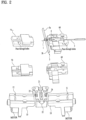
- FIG. 2 is a perspective diagram showing structures of an alignment part and a fusion splicing module of the fibre optic fusion splicer according to the present invention.
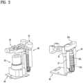
- FIG. 3 is a perspective diagram showing a structure of a lift module being operatively connected to a fusion splicing module and an optical module of the fibre optic fusion splicer according to the present invention.
- the fibre optic fusion splicer includes an alignment part (10), a fusion splicing module (20), an optical module (30), a support part (40), and a lift module (50). Additionally, the fibre optic fusion splicer according to the present invention may further include control buttons for controlling operations of the alignment part (10), the fusion splicing module (20), and the optical module (30), and a display part (not shown) for displaying images taken (or photographed or filmed) by the optical module (30).
- the fibre optic fusion splicer may also include a battery for power supply, a power supply port, and a data communication port for transmitting and/or receiving data.
- the alignment part (10) fixes and aligns first and second optical fibres (1 and 2) that are to be coupled by fusion (or fusion coupled).
- the alignment part (10) may be equipped with a first fixing part (11) accommodating the first optical fibre (1), and a second fixing part (12) accommodating the second optical fibre (2).
- the first holder (60) and the second holder (70) are equipped with a plurality of pass-through holes, and each of the first fixing part (11) and the second fixing part (12) may have a structure of a protruded bar that can be respectively inserted in the first holder (60) and the second holder (70). Accordingly, the first fixing part (11) and the second fixing part (12) each having the structure of a protruded bar respectively pass through the plurality of pass-through holes being provided in each of the first holder (60) and the second holder (70) so as to be fixed.
- the optical connector (4) is equipped with a protective cover (5) at its rear end.
- the protective cover (5) is adhered to the fused part of the first optical fibre and the second optical fibre while facing into the fused part, thereby covering the fused part.
- the protective cover (5) is coupled with one end, more specifically, the rear end of the optical connector (4) by having a pair of wing parts (5a and 5b) extend and spread out from the first optical fibre (1).
- a member is provided on inner surfaces of the wing parts so as to enable the adhesion of the wing parts.
- an elastic sheet having an adhesive deposited thereon may be provided on the inner surfaces of the wing parts.
- the material of the elastic sheet may correspond to any one of polyethylene, polyvinyl chloride, polyurethane, natural rubber, synthetic rubber, and a mixture of natural rubber and synthetic rubber.
- silicon may be deposited on the inner surfaces of the wing parts.
- the external surfaces of the wing parts are formed of a solid material.
- the first fixing part (11) and the second fixing part (12) being equipped in the alignment part (10) have a movable structure that allows the first optical fibre (1) and the second optical fibre (2) to be spliced at a fusion point that is provided between the electrode bars (21 and 22), which are equipped in the fusion splicing module (20). Therefore, the first fixing part (11) and the second fixing part (12) have a structure that is guided along a rail so as to advance (or move forward) toward the fusion point or to retreat (or move backward) from the fusion point to a predetermined range. It is preferable that a motor is provided for the forward or backward movements of the first fixing part (11) and the second fixing part (12).
- the fusion splicing module (20) is equipped with electrode bars (21 and 22) discharging electricity by the supplied power, and the electrode bars (21 and 22) perform fusion coupling of the first optical fibre (1) and the second optical fibre (2), which are fixed and aligned in the alignment part (10).
- the fusion splicing module (20) may be further equipped with v-grooves (23 and 24), which are used for aligning the first optical fibre (1) and the second optical fibre (2).
- the fibre optic fusion splicer according to the present invention may be further equipped with a cover (not shown).
- the fibre optic fusion splicer according to the present invention may also be further equipped with an LED lighting device (not shown) in its inside, so as to allow the optical module (30) to photograph (or film) the inside of the fibre optic fusion splicer even when it is covered by the cover (not shown).
- the optical module (30) is equipped with a lens and a camera, thereby being capable of photographing (or filming) the alignment state of the first optical fibre (1) and the second optical fibre (2), which is achieved by the alignment part (10), and photographing (or filming) the fusion coupling state of the first optical fibre (1) and the second optical fibre (2), which is achieved by the fusion splicing module (20). Thereafter, the photographed (or filmed) image(s) taken by the optical module (30) is/are displayed through a display part (not shown).
- the support part (40) corresponds to a supporting structure having the fusion splicing module (20) and the optical module (30) installed thereto.
- the support part (40) fixes the fusion splicing module (20) and the optical module (30) in a uniform frame.
- the lift module (50) ascends and descends (or lifts up and down) the support part (40) having the fusion splicing module (20) and the optical module (30) fixedly equipped thereto.
- the lift module (50) is equipped with a cylinder tube (51), a piston rod (52) being guided to the cylinder tube (51) and being ascended and descended (or lifted up and down), and a push-button switch (53).
- the support part (40) is fixedly coupled to the piston rod (52) so that the fusion splicing module (20) and the optical module (30) can be ascended and descended while being coupled to a structural body.
- the support part (40) is fixedly coupled to the piston rod (52)
- the fusion splicing module (20) and the optical module (30) which are fixedly equipped to the support part (40) are collectively ascended and descended.
- the push-button switch (53) is maneuvered (or operated) by the user for the lifting up and down (or ascending and descending) of the lift module (50).
- the push-button switch (53) is equipped with a button unit (53a), a lifting member (53b), and a fixing member (53c).
- the lifting member (53b) descends the piston rod (52) by applying pressure on a spring. Thereafter, when pushing the button unit (53a) once again, the lifting member (53b) ascends the piston rod (52) by using the restoring force of the spring.
- the fixing member (53c) fixes the lifting member (53b) or releases the fixed state of the lifting member (53b) at a position where the piston rod (52) is descended in accordance with the push operation (or maneuver) of the button unit (53a). More specifically, when the piston rod (52) is descended as pressure is applied to the spring when the button unit (53a) is pushed, the fixing member (53c) fixes the lifting member (53b) so as to restrict the ascending (or lifting up) of the lifting member (53b). Afterwards, when the button unit (53a) is pushed once again, the lifting member (53b) releases the fixed state of the lifting member (53b), so as to allow the piston rod (52) to be ascended (or lifted up) by using the restoring force of the spring.
- the optical fibres that are fusion-spliced by the fusion splicing module (20) are spaced apart from the electrode bars (21 and 22) as well as the v-grooves (23 and 24) so as to be stably separated from the fusion splicer without causing any damage to the spliced part.
- the fibre optic fusion splicer according to the present invention may be broadly applied in the fusion splicing technology for resolving the problems of alignment, stable separation, elimination of alignment errors, and so on, of optical fibres.
Landscapes
- Physics & Mathematics (AREA)
- General Physics & Mathematics (AREA)
- Optics & Photonics (AREA)
- Engineering & Computer Science (AREA)
- Plasma & Fusion (AREA)
- Mechanical Coupling Of Light Guides (AREA)
Claims (6)
- Une épisseuse de fusion de fibre optique, comprenant :une partie d'alignement (10) configurée pour fixer et aligner une première fibre optique (1) et une seconde fibre optique (2) qui doivent être couplées par fusion ;un module d'épissure par fusion (20) équipé de barres d'électrodes (21, 22) configurées pour coupler par fusion la première fibre optique (1) et la seconde fibre optique (2) étant fixées et alignées par la partie d'alignement (10) ;un module optique (30) configuré pour photographier ou filmer un état d'alignement de la première fibre optique (1) et de la seconde fibre optique (2) réalisé par la partie d'alignement (10) et un état de couplage par fusion de la première fibre optique (1) et de la seconde fibre optique (2) réalisé par le module d'épissure par fusion (20) ;une partie de support (40) équipée du module d'épissure par fusion (20) et du module optique (30) ;un module de levage (50) configuré pour monter et descendre la partie de support (40),caractérisé en ce quele module de levage (50) comporte un tube cylindrique (51) et une tige de piston (52) qui est guidée vers le tube cylindrique (51) et qui peut monter et descendre,la partie de support (40) est couplée de manière fixe à la tige de piston (52) et est montée et descendue par la tige de piston (52), de sorte que le module d'épissure par fusion (20) et le module optique (30), qui sont installés sur la partie de support (40), sont collectivement montés et descendus collectivement.
- L'épisseuse de fusion de fibre optique selon la revendication 1, dans laquelle la partie d'alignement (10) comprend :une première partie de fixation (11) configurée pour fixer un premier support (60) dans lequel est logée la première fibre optique (1) ; etune seconde partie de fixation (12) configurée pour fixer un second support (70) dans lequel est logée la seconde fibre optique (2).
- L'épisseuse de fusion de fibre optique selon la revendication 2, dans laquelle le premier support (60) fixé à la première partie de fixation (11) est configuré pour accueillir un connecteur optique amovible (4) comportant une virole (3) dans laquelle est enfermée la première fibre optique (1), et
dans laquelle un couvercle de protection (5) est équipé d'une extrémité arrière du connecteur optique (4), le couvercle de protection (5) étant configuré pour couvrir une partie fusionnée de la première fibre optique (1) et de la seconde fibre optique (2) en étant collé tout en faisant face à la partie fusionnée. - L'épisseuse de fusion de fibre optique selon la revendication 3, dans laquelle une paire de pièces d'aile (5a, 5b) s'étendant et se déployant à partir de la première fibre optique (1) est couplée à l'extrémité arrière du connecteur optique (4) et
dans laquelle le couvercle de protection (5) comporte une feuille élastique sur laquelle est déposé un adhésif sur les surfaces intérieures des pièces d'aile (5a, 5b) qui adhèrent mutuellement les unes aux autres ou comporte du silicium déposé sur les surfaces intérieures des pièces d'aile (5a, 5b) adhérant mutuellement l'une à l'autre. - L'épisseuse de fusion de fibre optique selon la revendication 1, comprenant en outre :
un interrupteur à bouton-poussoir (53) configuré pour faire monter et descendre le module de levage (50). - L'épisseuse de fusion de fibre optique selon la revendication 5, dans laquelle l'interrupteur à bouton-poussoir (53) comprend :une unité de bouton (53a) ;un élément de levage (53b) configuré pour faire descendre la tige de piston (52) en appliquant une pression sur un ressort lorsque l'unité de bouton (53a) est poussée et pour faire remonter la tige de piston (52) en utilisant une force de rappel du ressort lorsque l'unité de bouton (53a) est poussée une nouvelle fois ; etun élément de fixation (53c) configuré pour fixer l'élément de levage (53b) dans une position où la tige de piston (52) est descendue ou pour libérer l'état fixe de l'élément de levage (53b) en fonction de l'opération de poussée effectuée sur l'unité de bouton (53a).
Applications Claiming Priority (2)
| Application Number | Priority Date | Filing Date | Title |
|---|---|---|---|
| KR1020160155862A KR101859917B1 (ko) | 2016-11-22 | 2016-11-22 | 광섬유 융착기 |
| PCT/KR2017/003837 WO2018097420A1 (fr) | 2016-11-22 | 2017-04-07 | Dispositif d'épissage par fusion de fibres optiques |
Publications (4)
| Publication Number | Publication Date |
|---|---|
| EP3546997A1 EP3546997A1 (fr) | 2019-10-02 |
| EP3546997A4 EP3546997A4 (fr) | 2020-08-12 |
| EP3546997B1 true EP3546997B1 (fr) | 2024-11-20 |
| EP3546997C0 EP3546997C0 (fr) | 2024-11-20 |
Family
ID=62169992
Family Applications (1)
| Application Number | Title | Priority Date | Filing Date |
|---|---|---|---|
| EP17874172.4A Active EP3546997B1 (fr) | 2016-11-22 | 2017-04-07 | Dispositif d'épissage par fusion de fibres optiques |
Country Status (11)
| Country | Link |
|---|---|
| US (1) | US11002910B2 (fr) |
| EP (1) | EP3546997B1 (fr) |
| JP (1) | JP6730518B2 (fr) |
| KR (1) | KR101859917B1 (fr) |
| CN (1) | CN108089265B (fr) |
| BR (1) | BR112019010379A2 (fr) |
| CA (1) | CA3044392A1 (fr) |
| MX (1) | MX2019005936A (fr) |
| MY (1) | MY200075A (fr) |
| PH (1) | PH12019501145A1 (fr) |
| WO (1) | WO2018097420A1 (fr) |
Families Citing this family (7)
| Publication number | Priority date | Publication date | Assignee | Title |
|---|---|---|---|---|
| KR102086429B1 (ko) * | 2018-08-29 | 2020-03-09 | 솔텍인포넷 주식회사 | 광섬유 수평화가 가능한 광섬유 융착기 |
| CN111736263B (zh) * | 2020-07-24 | 2022-08-02 | 安徽睿光仪器设备有限公司 | 适用不同纤径光纤熔接的调准装置 |
| US11714236B2 (en) * | 2020-11-12 | 2023-08-01 | Ortronics, Inc. | Single-station splicing unit and method |
| JP1711675S (ja) * | 2021-10-15 | 2022-04-04 | 光ファイバ融着接続機 | |
| USD1104089S1 (en) * | 2021-12-17 | 2025-12-02 | Fiberfox, Inc. | Integrated fusion splicer |
| USD1101007S1 (en) * | 2022-04-07 | 2025-11-04 | Sumitomo Electric Optifrontier Co., Ltd. | Optical fiber fusion splicer |
| KR102789917B1 (ko) * | 2022-12-05 | 2025-04-01 | 주식회사 솔텍 | 오토 승강 모듈을 갖는 광섬유 융착접속장치 |
Citations (1)
| Publication number | Priority date | Publication date | Assignee | Title |
|---|---|---|---|---|
| US20140075999A1 (en) * | 2012-03-29 | 2014-03-20 | Fujikura Ltd. | Optical fiber fusion splicer |
Family Cites Families (14)
| Publication number | Priority date | Publication date | Assignee | Title |
|---|---|---|---|---|
| JPH0664214B2 (ja) * | 1986-03-12 | 1994-08-22 | 株式会社フジクラ | 高強度光ファイバの融着接続装置 |
| JP3520273B2 (ja) * | 2001-06-27 | 2004-04-19 | 株式会社フジクラ | 光ファイバ融着接続機および該接続機における放電ビーム判定法 |
| US7220061B2 (en) * | 2002-06-24 | 2007-05-22 | Diamond Sa | Connector-plug part for an optical plug-in connection, method for connecting a connector-plug part to the end of an optical waveguide cable and device for carrying out said method |
| US6764230B1 (en) * | 2003-03-21 | 2004-07-20 | Future Instruments Fiber Optics Ab | Optical fiber splicing device |
| JP2005352167A (ja) * | 2004-06-10 | 2005-12-22 | Fujikura Ltd | 突き合わせ装置およびこの突き合わせ装置を備えた融着接続装置 |
| JP5184865B2 (ja) * | 2006-11-13 | 2013-04-17 | 住友電気工業株式会社 | 光コネクタ |
| CH700691B1 (de) * | 2009-03-20 | 2020-09-15 | Diamond Sa | Vorrichtung und Verfahren zum Spleissen von Lichtwellenleitern, sowie Verwendung eines Endstückes in einer Vorrichtung zum Spleissen. |
| JP5799471B2 (ja) | 2011-02-18 | 2015-10-28 | Seiオプティフロンティア株式会社 | 融着部の補強方法及び融着接続機 |
| JP5810463B2 (ja) | 2011-07-25 | 2015-11-11 | Seiオプティフロンティア株式会社 | 融着接続機 |
| KR20130063770A (ko) * | 2011-12-07 | 2013-06-17 | 한국전자통신연구원 | 광섬유 융착 접속기 |
| JP5209126B1 (ja) * | 2012-03-29 | 2013-06-12 | 株式会社フジクラ | 光ファイバ融着接続機 |
| CN202904059U (zh) * | 2012-11-21 | 2013-04-24 | 武汉拓尔奇光电技术有限公司 | 一种激光振镜方式剥覆、端面处理、熔接光缆的装置 |
| KR20160100175A (ko) | 2015-02-13 | 2016-08-23 | 주식회사 삼홍사 | 높낮이 조절이 가능한 책상 |
| CN204790062U (zh) * | 2015-05-30 | 2015-11-18 | 李亮 | 一种装配有光纤成像装置的光纤熔接机 |
-
2016
- 2016-11-22 KR KR1020160155862A patent/KR101859917B1/ko active Active
-
2017
- 2017-01-10 CN CN201710014599.8A patent/CN108089265B/zh active Active
- 2017-04-07 MY MYPI2019002850A patent/MY200075A/en unknown
- 2017-04-07 EP EP17874172.4A patent/EP3546997B1/fr active Active
- 2017-04-07 CA CA3044392A patent/CA3044392A1/fr not_active Abandoned
- 2017-04-07 BR BR112019010379-1A patent/BR112019010379A2/pt not_active IP Right Cessation
- 2017-04-07 JP JP2019514697A patent/JP6730518B2/ja active Active
- 2017-04-07 WO PCT/KR2017/003837 patent/WO2018097420A1/fr not_active Ceased
- 2017-04-07 MX MX2019005936A patent/MX2019005936A/es unknown
- 2017-04-07 US US16/305,038 patent/US11002910B2/en active Active
-
2019
- 2019-05-22 PH PH12019501145A patent/PH12019501145A1/en unknown
Patent Citations (1)
| Publication number | Priority date | Publication date | Assignee | Title |
|---|---|---|---|---|
| US20140075999A1 (en) * | 2012-03-29 | 2014-03-20 | Fujikura Ltd. | Optical fiber fusion splicer |
Also Published As
| Publication number | Publication date |
|---|---|
| EP3546997A4 (fr) | 2020-08-12 |
| WO2018097420A1 (fr) | 2018-05-31 |
| PH12019501145A1 (en) | 2019-12-16 |
| US11002910B2 (en) | 2021-05-11 |
| BR112019010379A2 (pt) | 2019-11-12 |
| MY200075A (en) | 2023-12-06 |
| EP3546997A1 (fr) | 2019-10-02 |
| CN108089265A (zh) | 2018-05-29 |
| MX2019005936A (es) | 2019-11-18 |
| CN108089265B (zh) | 2021-06-22 |
| JP2019520613A (ja) | 2019-07-18 |
| CA3044392A1 (fr) | 2018-05-31 |
| EP3546997C0 (fr) | 2024-11-20 |
| JP6730518B2 (ja) | 2020-07-29 |
| US20200319407A1 (en) | 2020-10-08 |
| KR101859917B1 (ko) | 2018-05-23 |
Similar Documents
| Publication | Publication Date | Title |
|---|---|---|
| EP3546997B1 (fr) | Dispositif d'épissage par fusion de fibres optiques | |
| US9091825B2 (en) | Optical fiber connector, optical fiber connector assembling method, fusion-spliced portion reinforcing method, pin clamp, cap-attached optical fiber connector, optical fiber connector cap, optical fiber connector assembling tool, and optical fiber connector assembling set | |
| EP3012673B1 (fr) | Épisseur par fusion de fibre optique et appareil d'épissurage de fibres optiques par fusion équipé de celui-ci | |
| US9411101B2 (en) | Optical fiber connector, optical fiber connector assembling method, optical fiber connector assembling tool, and optical fiber connector assembling set | |
| CN101297224B (zh) | 光纤连接器、光纤分配装置、以及用于光纤连接器的光纤端接平台 | |
| US20140037250A1 (en) | Field installed optical fiber connector for jacketed fiber cable and termination method | |
| US20150003790A1 (en) | Field mountable duplex optical fiber connector with mechanical splice elements | |
| US20100260458A1 (en) | Optical fiber cable holder, fusion splicer including the holder, and fusion splicing method using the holder | |
| EP2495591B1 (fr) | Support de ferrule | |
| JP6554734B2 (ja) | 光ファイバの融着接続方法および融着接続装置 | |
| KR20160110105A (ko) | 광파이버의 융착 접속 방법 및 융착 접속 장치 | |
| US8915100B2 (en) | Optical fiber end processing method and optical fiber end processing apparatus | |
| KR102086429B1 (ko) | 광섬유 수평화가 가능한 광섬유 융착기 | |
| TWI611229B (zh) | 光連接器之製造方法、及光纖插入裝置 | |
| KR20130063770A (ko) | 광섬유 융착 접속기 | |
| CN112505850A (zh) | 一种便于光电光纤对接用连接头及其连接方法 | |
| US11487062B2 (en) | Field assembly optical connector configured to prevent optical fiber bending | |
| CN103376513B (zh) | 光纤连接器 | |
| KR20110050335A (ko) | 융착접속기와 이를 이용하는 현장조립형 광 커넥터 | |
| KR20230045766A (ko) | 한손 동작이 가능한 초소형 융착접속 광커넥터 제조 장치 | |
| CN117687149A (zh) | 一种光缆熔融对接装置及其方法 | |
| JP4276243B2 (ja) | 光ファイバ接続替え装置 | |
| EP2084564B1 (fr) | Procédé d'installation d'une unité de fibre optique |
Legal Events
| Date | Code | Title | Description |
|---|---|---|---|
| STAA | Information on the status of an ep patent application or granted ep patent |
Free format text: STATUS: THE INTERNATIONAL PUBLICATION HAS BEEN MADE |
|
| PUAI | Public reference made under article 153(3) epc to a published international application that has entered the european phase |
Free format text: ORIGINAL CODE: 0009012 |
|
| STAA | Information on the status of an ep patent application or granted ep patent |
Free format text: STATUS: REQUEST FOR EXAMINATION WAS MADE |
|
| 17P | Request for examination filed |
Effective date: 20190529 |
|
| AK | Designated contracting states |
Kind code of ref document: A1 Designated state(s): AL AT BE BG CH CY CZ DE DK EE ES FI FR GB GR HR HU IE IS IT LI LT LU LV MC MK MT NL NO PL PT RO RS SE SI SK SM TR |
|
| AX | Request for extension of the european patent |
Extension state: BA ME |
|
| DAV | Request for validation of the european patent (deleted) | ||
| DAX | Request for extension of the european patent (deleted) | ||
| A4 | Supplementary search report drawn up and despatched |
Effective date: 20200713 |
|
| RIC1 | Information provided on ipc code assigned before grant |
Ipc: G02B 6/38 20060101ALI20200707BHEP Ipc: G02B 6/255 20060101AFI20200707BHEP |
|
| STAA | Information on the status of an ep patent application or granted ep patent |
Free format text: STATUS: EXAMINATION IS IN PROGRESS |
|
| 17Q | First examination report despatched |
Effective date: 20220711 |
|
| GRAP | Despatch of communication of intention to grant a patent |
Free format text: ORIGINAL CODE: EPIDOSNIGR1 |
|
| STAA | Information on the status of an ep patent application or granted ep patent |
Free format text: STATUS: GRANT OF PATENT IS INTENDED |
|
| INTG | Intention to grant announced |
Effective date: 20240611 |
|
| GRAS | Grant fee paid |
Free format text: ORIGINAL CODE: EPIDOSNIGR3 |
|
| GRAA | (expected) grant |
Free format text: ORIGINAL CODE: 0009210 |
|
| STAA | Information on the status of an ep patent application or granted ep patent |
Free format text: STATUS: THE PATENT HAS BEEN GRANTED |
|
| AK | Designated contracting states |
Kind code of ref document: B1 Designated state(s): AL AT BE BG CH CY CZ DE DK EE ES FI FR GB GR HR HU IE IS IT LI LT LU LV MC MK MT NL NO PL PT RO RS SE SI SK SM TR |
|
| REG | Reference to a national code |
Ref country code: GB Ref legal event code: FG4D |
|
| REG | Reference to a national code |
Ref country code: CH Ref legal event code: EP |
|
| REG | Reference to a national code |
Ref country code: DE Ref legal event code: R096 Ref document number: 602017086300 Country of ref document: DE |
|
| REG | Reference to a national code |
Ref country code: IE Ref legal event code: FG4D |
|
| U01 | Request for unitary effect filed |
Effective date: 20241217 |
|
| U07 | Unitary effect registered |
Designated state(s): AT BE BG DE DK EE FI FR IT LT LU LV MT NL PT RO SE SI Effective date: 20250102 |
|
| U20 | Renewal fee for the european patent with unitary effect paid |
Year of fee payment: 9 Effective date: 20250224 |
|
| PG25 | Lapsed in a contracting state [announced via postgrant information from national office to epo] |
Ref country code: HR Free format text: LAPSE BECAUSE OF FAILURE TO SUBMIT A TRANSLATION OF THE DESCRIPTION OR TO PAY THE FEE WITHIN THE PRESCRIBED TIME-LIMIT Effective date: 20241120 Ref country code: IS Free format text: LAPSE BECAUSE OF FAILURE TO SUBMIT A TRANSLATION OF THE DESCRIPTION OR TO PAY THE FEE WITHIN THE PRESCRIBED TIME-LIMIT Effective date: 20250320 |
|
| PG25 | Lapsed in a contracting state [announced via postgrant information from national office to epo] |
Ref country code: ES Free format text: LAPSE BECAUSE OF FAILURE TO SUBMIT A TRANSLATION OF THE DESCRIPTION OR TO PAY THE FEE WITHIN THE PRESCRIBED TIME-LIMIT Effective date: 20241120 |
|
| PG25 | Lapsed in a contracting state [announced via postgrant information from national office to epo] |
Ref country code: NO Free format text: LAPSE BECAUSE OF FAILURE TO SUBMIT A TRANSLATION OF THE DESCRIPTION OR TO PAY THE FEE WITHIN THE PRESCRIBED TIME-LIMIT Effective date: 20250220 |
|
| PG25 | Lapsed in a contracting state [announced via postgrant information from national office to epo] |
Ref country code: GR Free format text: LAPSE BECAUSE OF FAILURE TO SUBMIT A TRANSLATION OF THE DESCRIPTION OR TO PAY THE FEE WITHIN THE PRESCRIBED TIME-LIMIT Effective date: 20250221 |
|
| PG25 | Lapsed in a contracting state [announced via postgrant information from national office to epo] |
Ref country code: PL Free format text: LAPSE BECAUSE OF FAILURE TO SUBMIT A TRANSLATION OF THE DESCRIPTION OR TO PAY THE FEE WITHIN THE PRESCRIBED TIME-LIMIT Effective date: 20241120 |
|
| PG25 | Lapsed in a contracting state [announced via postgrant information from national office to epo] |
Ref country code: RS Free format text: LAPSE BECAUSE OF FAILURE TO SUBMIT A TRANSLATION OF THE DESCRIPTION OR TO PAY THE FEE WITHIN THE PRESCRIBED TIME-LIMIT Effective date: 20250220 |
|
| PG25 | Lapsed in a contracting state [announced via postgrant information from national office to epo] |
Ref country code: SM Free format text: LAPSE BECAUSE OF FAILURE TO SUBMIT A TRANSLATION OF THE DESCRIPTION OR TO PAY THE FEE WITHIN THE PRESCRIBED TIME-LIMIT Effective date: 20241120 |
|
| PG25 | Lapsed in a contracting state [announced via postgrant information from national office to epo] |
Ref country code: SK Free format text: LAPSE BECAUSE OF FAILURE TO SUBMIT A TRANSLATION OF THE DESCRIPTION OR TO PAY THE FEE WITHIN THE PRESCRIBED TIME-LIMIT Effective date: 20241120 |
|
| PG25 | Lapsed in a contracting state [announced via postgrant information from national office to epo] |
Ref country code: CZ Free format text: LAPSE BECAUSE OF FAILURE TO SUBMIT A TRANSLATION OF THE DESCRIPTION OR TO PAY THE FEE WITHIN THE PRESCRIBED TIME-LIMIT Effective date: 20241120 |
|
| PLBE | No opposition filed within time limit |
Free format text: ORIGINAL CODE: 0009261 |
|
| STAA | Information on the status of an ep patent application or granted ep patent |
Free format text: STATUS: NO OPPOSITION FILED WITHIN TIME LIMIT |
|
| 26N | No opposition filed |
Effective date: 20250821 |
|
| REG | Reference to a national code |
Ref country code: CH Ref legal event code: H13 Free format text: ST27 STATUS EVENT CODE: U-0-0-H10-H13 (AS PROVIDED BY THE NATIONAL OFFICE) Effective date: 20251125 |
|
| PG25 | Lapsed in a contracting state [announced via postgrant information from national office to epo] |
Ref country code: MC Free format text: LAPSE BECAUSE OF FAILURE TO SUBMIT A TRANSLATION OF THE DESCRIPTION OR TO PAY THE FEE WITHIN THE PRESCRIBED TIME-LIMIT Effective date: 20241120 |
|
| GBPC | Gb: european patent ceased through non-payment of renewal fee |
Effective date: 20250407 |
|
| PG25 | Lapsed in a contracting state [announced via postgrant information from national office to epo] |
Ref country code: GB Free format text: LAPSE BECAUSE OF NON-PAYMENT OF DUE FEES Effective date: 20250407 |
|
| PG25 | Lapsed in a contracting state [announced via postgrant information from national office to epo] |
Ref country code: CH Free format text: LAPSE BECAUSE OF NON-PAYMENT OF DUE FEES Effective date: 20250430 |
|
| PG25 | Lapsed in a contracting state [announced via postgrant information from national office to epo] |
Ref country code: IE Free format text: LAPSE BECAUSE OF NON-PAYMENT OF DUE FEES Effective date: 20250407 |