EP3547023B1 - Projektionsvorrichtung - Google Patents
Projektionsvorrichtung Download PDFInfo
- Publication number
- EP3547023B1 EP3547023B1 EP19165780.8A EP19165780A EP3547023B1 EP 3547023 B1 EP3547023 B1 EP 3547023B1 EP 19165780 A EP19165780 A EP 19165780A EP 3547023 B1 EP3547023 B1 EP 3547023B1
- Authority
- EP
- European Patent Office
- Prior art keywords
- light
- projection apparatus
- optical axis
- module
- collimating lens
- Prior art date
- Legal status (The legal status is an assumption and is not a legal conclusion. Google has not performed a legal analysis and makes no representation as to the accuracy of the status listed.)
- Active
Links
Images




Classifications
-
- G—PHYSICS
- G03—PHOTOGRAPHY; CINEMATOGRAPHY; ANALOGOUS TECHNIQUES USING WAVES OTHER THAN OPTICAL WAVES; ELECTROGRAPHY; HOLOGRAPHY
- G03B—APPARATUS OR ARRANGEMENTS FOR TAKING PHOTOGRAPHS OR FOR PROJECTING OR VIEWING THEM; APPARATUS OR ARRANGEMENTS EMPLOYING ANALOGOUS TECHNIQUES USING WAVES OTHER THAN OPTICAL WAVES; ACCESSORIES THEREFOR
- G03B21/00—Projectors or projection-type viewers; Accessories therefor
- G03B21/14—Details
- G03B21/147—Optical correction of image distortions, e.g. keystone
-
- G—PHYSICS
- G02—OPTICS
- G02B—OPTICAL ELEMENTS, SYSTEMS OR APPARATUS
- G02B19/00—Condensers, e.g. light collectors or similar non-imaging optics
- G02B19/0004—Condensers, e.g. light collectors or similar non-imaging optics characterised by the optical means employed
- G02B19/0009—Condensers, e.g. light collectors or similar non-imaging optics characterised by the optical means employed having refractive surfaces only
- G02B19/0014—Condensers, e.g. light collectors or similar non-imaging optics characterised by the optical means employed having refractive surfaces only at least one surface having optical power
-
- G—PHYSICS
- G02—OPTICS
- G02B—OPTICAL ELEMENTS, SYSTEMS OR APPARATUS
- G02B19/00—Condensers, e.g. light collectors or similar non-imaging optics
- G02B19/0033—Condensers, e.g. light collectors or similar non-imaging optics characterised by the use
- G02B19/0047—Condensers, e.g. light collectors or similar non-imaging optics characterised by the use for use with a light source
-
- G—PHYSICS
- G03—PHOTOGRAPHY; CINEMATOGRAPHY; ANALOGOUS TECHNIQUES USING WAVES OTHER THAN OPTICAL WAVES; ELECTROGRAPHY; HOLOGRAPHY
- G03B—APPARATUS OR ARRANGEMENTS FOR TAKING PHOTOGRAPHS OR FOR PROJECTING OR VIEWING THEM; APPARATUS OR ARRANGEMENTS EMPLOYING ANALOGOUS TECHNIQUES USING WAVES OTHER THAN OPTICAL WAVES; ACCESSORIES THEREFOR
- G03B21/00—Projectors or projection-type viewers; Accessories therefor
- G03B21/14—Details
- G03B21/20—Lamp housings
- G03B21/2066—Reflectors in illumination beam
-
- G—PHYSICS
- G03—PHOTOGRAPHY; CINEMATOGRAPHY; ANALOGOUS TECHNIQUES USING WAVES OTHER THAN OPTICAL WAVES; ELECTROGRAPHY; HOLOGRAPHY
- G03B—APPARATUS OR ARRANGEMENTS FOR TAKING PHOTOGRAPHS OR FOR PROJECTING OR VIEWING THEM; APPARATUS OR ARRANGEMENTS EMPLOYING ANALOGOUS TECHNIQUES USING WAVES OTHER THAN OPTICAL WAVES; ACCESSORIES THEREFOR
- G03B21/00—Projectors or projection-type viewers; Accessories therefor
- G03B21/14—Details
- G03B21/20—Lamp housings
- G03B21/208—Homogenising, shaping of the illumination light
-
- H—ELECTRICITY
- H04—ELECTRIC COMMUNICATION TECHNIQUE
- H04N—PICTORIAL COMMUNICATION, e.g. TELEVISION
- H04N9/00—Details of colour television systems
- H04N9/12—Picture reproducers
- H04N9/31—Projection devices for colour picture display, e.g. using electronic spatial light modulators [ESLM]
- H04N9/3141—Constructional details thereof
- H04N9/315—Modulator illumination systems
- H04N9/3152—Modulator illumination systems for shaping the light beam
Definitions
- the present disclosure relates to a projection apparatus.
- the light valve thereof When a projection apparatus performs image projection, the light valve thereof usually converts an illumination beam into an image beam and reflects the image beam to a projection lens, where the image beam is projected by the projection lens onto a screen to form images.
- a projection apparatus of some conventional designs may use a TIR prism, a RTIR prism, or multiple mirrors as a light conversion component to achieve high efficiency and low illumination crosstalk, but the size of the projection apparatus may not be easily reduced and the image provided by the projection apparatus may have a small viewing angle (e.g., about 40 degrees).
- a projection apparatus of another conventional design uses a field lens as a light conversion component, which allows the projection apparatus to have a smaller volume and a larger viewing angle.
- the projection apparatus of this design may have a poor optical efficiency and a relatively high crosstalk, which will result in a significant reduction in the quality of the projected image.
- a projection apparatus which includes a light source, a light valve, a light uniforming device, and a lens module.
- the light source provides an illumination beam.
- the light valve on a transmission path of the illumination beam converts the illumination beam into an image beam.
- the light valve has an active surface with a rectangular shape.
- the light uniforming device is between the light source and the light value.
- the lens module is between the light uniforming device and the light value.
- a refractive power of the lens module along a first direction is different from a refractive power of the lens module along a second direction.
- An f-number of the illumination beam along a direction parallel to a long side of the active surface of the light valve is greater than an f-number thereof along a direction parallel to a short side of the active surface of the light valve.
- an illuminating optical system including a light source that produces a light beam generally parallel to its optical axis toward a pair of fly-eye lenses in optical series for mixing light in the light beam in order to provide more uniform illumination.
- a condensing optical system converges and deflects the light from the fly-eye lens at an angle to a generally planar reflective display device, such as a liquid crystal display device.
- the fly-eye lenses and the reflective display device are parallel or nearly parallel to one another.
- the fly-eye lenses may be centered on the optical axis of the light source, and the optical axis of the light source may be parallel, or nearly parallel, to the direction that light from the reflective display device is reflected.
- a projection display device may include a projection lens that focuses the light from the reflective display device onto a screen.
- Document US 2012/249971 A1 relates to a projection apparatus including a light source, a light valve, a light uniforming device, and a first curved-surface reflection device.
- the light source provides an illumination beam.
- the light valve is disposed on a transmission path of the illumination beam for converting the illumination beam into an image beam.
- the light valve has an active surface that substantially has a rectangular contour.
- the light uniforming device is disposed on the transmission path of the illumination beam and between the light source and the light valve.
- the first curved-surface reflection device is disposed on the transmission path of the illumination beam and between the light source and the light valve for reflecting the illumination beam to the light valve.
- a curvature of the first curved-surface reflection device along a first direction is not equal to a curvature of the first curved-surface reflection device along a second direction.
- the illumination system provides an illumination beam.
- the light valve is disposed on a transmission path of the illumination beam, and is used to convert the illumination beam into an image beam.
- the projection lens is disposed on a transmission path of the image beam and has a lens group, and the lens group includes a plurality of lenses.
- a lens of the lenses closest to the light valve has an optical axis, a first edge, and a second edge. The first edge and the second edge are located on opposite sides of the optical axis, and a ratio of a distance from the first edge to the optical axis and a distance from the second edge to the optical axis is greater than or equal to 0 and less than 1.
- An aspect of the disclosure is to provide a projection apparatus that can efficiently solve the aforementioned problems.
- a projection apparatus includes a light source, a light reflective member, a light valve, and a light beam adjusting member.
- the light source is configured to provide an illumination beam.
- the light reflective member is configured to reflect the illumination beam.
- the light valve is configured to convert the illumination beam reflected by the light reflective member into an image beam.
- the light beam adjusting member is optically coupled between the light source and the light reflective member and includes a collimating lens module.
- the collimating lens module has a light entering surface and a light leaving surface at opposite sides thereof. The light entering surface and the light leaving surface respectively have a first optical axis and a second optical axis extending along different directions.
- the light beam adjusting member further includes a light homogenizing module.
- the light homogenizing module is between the light source and the collimating lens module and has a third optical axis. An angle between the first optical axis and the third optical axis is different from an angle between the second optical axis and the third optical axis.
- the light homogenizing module is a light integrator.
- the light integrator includes a plurality of microlenses attached to each other and arranged in an array.
- the third optical axis passes through a centroid of the microlenses.
- the third optical axis passes through one of the microlenses.
- light homogenizing module includes a one-piece microlens array.
- the collimating lens module is a unitary lens structure.
- the collimating lens module includes two sub lenses sequentially arranged between the light source and the light reflective member.
- the light entering surface and the light leaving surface are respectively on the two sub lenses.
- the two sub lenses are attached to each other.
- the two sub lenses are spaced apart from each other.
- the projection apparatus further includes a projection lens.
- the projection lens is configured to receive the image beam.
- the projection apparatus further includes a field lens.
- the field lens is optically coupled between the light reflective member and the light valve and between the light valve and the projection lens.
- the projection apparatus further includes a field lens between the light reflective member and the light valve.
- the illumination beam is reflected to the light valve through the field lens.
- the image beam propagates through the field lens.
- the light entering surface is a portion of the collimating lens module facing toward and closest to the light source.
- the light leaving surface is a portion of the collimating lens module facing toward and closest to the light reflective member.
- the first optical axis passes through a center of the light entering surface.
- the first optical axis is perpendicular to the light entering surface.
- the second optical axis passes through a center of the light leaving surface.
- the second optical axis is perpendicular to the light leaving surface.
- the collimating lens module of the light beam adjusting member has a splitting optical axis (i.e., a discontinuous optical axis).
- the light entering surface and the light leaving surface of the collimating lens module respectively have two optical axes extending along different directions.
- the light homogenizing module of the light beam adjusting member has an optical axis, and an angle between the optical axes of the light entering surface and the light homogenizing module is different from an angle between the light leaving surface and the light homogenizing module.
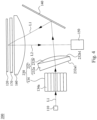
- Fig. 1 is a schematic diagram of a projection apparatus 100 according to some embodiments of the present disclosure.
- the projection apparatus 100 includes a light source 110, a light valve 120, a light beam adjusting member 130, and a light reflective member 140.
- the light source 110 is configured to provide an illumination beam L1 which is depicted in the form of ray in Fig. 1 for simplicity.
- the light source 110 may include at least one light emitting diode (LED), an ultra-high pressure lamp (UHP lamp), or the like.
- LED light emitting diode
- UHP lamp ultra-high pressure lamp
- the light reflective member 140 is configured to reflect the illumination beam propagating from the light source 110.
- the light reflective member 140 is, for example, a reflective mirror, but the disclosure is not limited in this regard.
- the light valve 120 is configured to convert the illumination beam L1 reflected by the light reflective member 140 into an image beam L2 which is depicted in the form of ray in Fig. 1 for simplicity.
- the light beam adjusting member 130 is optically coupled between the light source 110 and the light reflective member 140. That is, the illumination beam L1 propagates from the light source 110 to the light reflective member 140 via the light beam adjusting member 130.
- the light beam adjusting member 130 includes a collimating lens module 132 and a light homogenizing module 134.
- the light homogenizing module 134 is between the light source 110 and the collimating lens module 132.
- the light homogenizing module 134 is configured to homogenize the illumination beam L1 passing through the light homogenizing module 134 and adjust the light radiation pattern of the illumination beam L1 passing through the light homogenizing module 134.
- the light radiation pattern of the illumination beam L1 transmitted to the light valve 120 is a rectangular shape as well.
- the method to adjust the light radiation pattern of the illumination beam L1 may be implemented by means of the light homogenizing module 134.
- the collimating lens module 132 is between the light homogenizing module 134 and the light reflective member 140.
- the collimating lens module 132 is configured to narrow the illumination beam L1 propagating from the light homogenizing module 134.
- the "narrow” may mean either to cause the rays of the illumination beam L1 to become more aligned in a specific direction, or to cause the spatial cross section of the illumination beam L1 to become smaller.
- the projection apparatus 100 further includes a projection lens 150.
- the projection lens 150 is configured to receive the image beam L2.
- the projection apparatus 100 further includes a field lens 160.
- the field lens 160 is optically coupled between the light reflective member 140 and the light valve 120 and between the light valve 120 and the projection lens 150. That is, the field lens 160 is on the propagating paths of the illumination beam L1 and the image beam L2.
- the illumination beam L1 is reflected to the light valve 120 through the field lens 160, and the image beam L2 propagates from the light valve 120 to the projection lens 150 through the field lens 160.
- the field lens 160 is configured to converge the image beam L2 and transmit the image beam L2 to the projection lens 150.
- the projection apparatus 100 may further include a protection cap 170 between the light valve 120 and the field lens 160 and in front of the light valve 120 for protecting the light valve 120.
- the light valve 120 is, for example, a digital micro-mirror device (DMD) having on its active surface several hundred thousand microscopic mirrors arranged in a rectangular array which correspond to the pixels in the image to be displayed.
- the mirrors can be individually rotated to an on or off state.
- the illumination beam L1 reflected by the light reflective member 140 is reflected by the mirrors to form the image beam L2 which propagates to the projection lens 150 making the pixels appear bright on the screen.
- the illumination beam L1 reflected by the light reflective member 140 is directed elsewhere by the mirrors, making the pixels appear dark.
- Fig. 2 is an enlarged diagram of the light beam adjusting member 130 shown in Fig. 1 .
- the collimating lens module 132 has a light entering surface 132a and a light leaving surface 132b at opposite sides thereof.
- the light entering surface 132a is a portion of the collimating lens module 132 facing toward and closest to the light source 110.
- the light leaving surface 132b is a portion of the collimating lens module 132 facing toward and closest to the light reflective member 140.
- the light entering surface 132a and the light leaving surface 132b respectively have a first optical axis A1 and a second optical axis A2 extending along different directions.
- the first optical axis A1 passes through a center C1 of the light entering surface 132a and is perpendicular to the light entering surface 132a.
- the second optical axis A2 passes through a center C2 of the light leaving surface 132b and is perpendicular to the light leaving surface 132b.
- the collimating lens module 132 has a splitting optical axis (i.e., a discontinuous optical axis).
- the center C1 of the light entering surface 132a refers to the centroid of the light entering surface 132a.
- the center C2 of the light leaving surface 132b refers to the centroid of the light leaving surface 132b.
- the light homogenizing module 134 has a third optical axis A3. Specifically, an angle ⁇ 1 between the first optical axis A1 and the third optical axis A3 is different from an angle ⁇ 2 between the second optical axis A2 and the third optical axis A3.
- a high optical efficiency and a relatively low crosstalk can be achieved by the projection apparatus 100, as well as a high image quality can be obtained.
- a solid angle of the illumination beam L1 incident to the light valve 120 can be well controlled.
- chief ray angles of the illumination beam L1 incident to the light valve 120 may be controlled to be less than 3 degrees.
- some design parameters of the collimating lens module 132 can be adjusted by the assistance of an optical simulation software, so as to better control the solid angle of the illumination beam L1 incident to the light valve 120.
- Fig. 3 is a schematic diagram illustrating some components of the projection apparatus 100 and rays of the illumination beam L1 and the image beam L2 propagating thereamong.
- rays e.g., a central ray L11 and peripheral rays L12, L13
- the illumination beam L1 may reach the active surface of the light valve 120 with a substantially identical incident angle, such that rays (e.g., a central ray L21 and peripheral rays L22, L23) of the image beam L2 leaving the light valve 120 may be substantially parallel to each other.
- the rays of the image beam L2 leaving the light valve 120 may be substantially perpendicular to the active surface of the light valve 120. As such, the image beam L2 may completely enter the projection lens 150 more easily, and thus the loss of optical efficiency of the projection apparatus 100 can be effectively reduced.
- a conventional projection apparatus adopting a light beam adjusting member having a single optical axis i.e., without splitting
- there is no way for rays of the illumination beam to reach the light valve with a predetermined incident angle which results in unevenness of the illumination beam and in turn reduces the optical efficiency (e.g., about 20% or more).
- the light beam adjusting member 130 with the splitting optical axis in the projection apparatus 100 can also uniformize the aberration caused by the field lens 160 on the propagating path of the illumination beam L1, so that the generation of crosstalk can be reduced and the illumination beam L1 incident on the light valve 120 may be more uniform (i.e., spot sizes of the illumination beam L1 is more uniform).
- the conventional light beam adjusting member having the single optical axis may cause the distortion of illumination area when the illumination beam incident onto the light valve.
- the collimating lens module 132 is a unitary lens structure.
- the light homogenizing module 134 is a light integrator.
- the light integrator includes a plurality of microlenses 134a attached to each other and arranged in an array (e.g., a rectangular array).
- the third optical axis A3 passes through a centroid C3 of the microlenses 134a, in which the centroid C3 is on one of the microlenses 134a.
- the centroid C3 may be spaced apart from the microlenses 134a.
- Fig. 4 is a schematic diagram of a projection apparatus 200 according to some embodiments of the present disclosure.
- the projection apparatus 200 includes a light source 110, a light valve 120, a light beam adjusting member 230, a light reflective member 140, a projection lens 150, a field lens 160, and a protection cap 170, in which the light beam adjusting member 230 includes a collimating lens module 232 and a light homogenizing module 134.
- the light source 110, the light valve 120, the light homogenizing module 134, the light reflective member 140, the projection lens 150, the field lens 160, and the protection cap 170 are identical or similar to those of the embodiments as illustrated by Fig.
- the collimating lens module 232 of the light beam adjusting member 230 includes two sub lenses 232a, 232b attached to each other and sequentially arranged between the light source 110 and the light reflective member 140.
- the two sub lenses 232a, 232b respectively have a light entering surface 232a1 and a light leaving surface 232b1.
- the light entering surface 232a1 is a portion of the collimating lens module 232 facing toward and closest to the light source 110.
- the light leaving surface 232b1 is a portion of the collimating lens module 232 facing toward and closest to the light reflective member 140.
- the number of the sub lenses included by the collimating lens module 232 may be more than two.
- Fig. 5 is a schematic diagram of a projection apparatus 300 according to some embodiments of the present disclosure.
- the projection apparatus 300 includes a light source 110, a light valve 120, a light beam adjusting member 330, a light reflective member 140, a projection lens 150, a field lens 160, and a protection cap 170, in which the light beam adjusting member 330 includes a collimating lens module 332 and a light homogenizing module 134.
- the light source 110, the light valve 120, the light homogenizing module 134, the light reflective member 140, the projection lens 150, the field lens 160, and the protection cap 170 are identical or similar to those of the embodiments as illustrated by Fig.
- the collimating lens module 332 of the light beam adjusting member 330 also includes two sub lenses 332a, 332b, but the two sub lenses 332a, 332b spaced apart from each other.
- the two sub lenses 332a, 332b respectively have a light entering surface 332a1 and a light leaving surface 332b1.
- the light entering surface 332a1 is a portion of the collimating lens module 332 facing toward and closest to the light source 110.
- the light leaving surface 332b1 is a portion of the collimating lens module 332 facing toward and closest to the light reflective member 140.
- the collimating lens module 332 may include one or more additional sub lenses between the sub lenses 332a, 332b.
- Fig. 6 is a schematic diagram of a projection apparatus 400 according to some embodiments of the present disclosure.
- the projection apparatus 400 includes a light source 110, a light valve 120, a light beam adjusting member 430, a light reflective member 140, a projection lens 150, a field lens 160, and a protection cap 170, in which the light beam adjusting member 430 includes a collimating lens module 132 and a light homogenizing module 434.
- the light source 110, the light valve 120, the collimating lens module 132, the light reflective member 140, the projection lens 150, the field lens 160, and the protection cap 170 are identical or similar to those of the embodiments as illustrated by Fig.
- the light homogenizing module 434 is a light integrator, and the light integrator is a unitary lens structure.
- the light homogenizing module 434 is also configured to homogenize the illumination beam L1 passing through the light homogenizing module 434 and adjust the light radiation pattern of the illumination beam L1 passing through the light homogenizing module 434.
- Fig. 7 is a schematic diagram of a projection apparatus 500 according to some embodiments of the present disclosure.
- the projection apparatus 500 includes a light source 110, a light valve 120, a light beam adjusting member 530, a light reflective member 140, a projection lens 150, a field lens 160, and a protection cap 170, in which the light beam adjusting member 530 includes a collimating lens module 132 and a light homogenizing module 534.
- the light source 110, the light valve 120, the collimating lens module 132, the light reflective member 140, the projection lens 150, the field lens 160, and the protection cap 170 are identical or similar to those of the embodiments as illustrated by Fig.
- the light homogenizing module 534 includes two sub lens arrays 534a, 534b.
- the two sub lens arrays 534a, 534b are sequentially arranged between the light source 110 and the collimating lens module 132.
- the light homogenizing module 534 is also configured to homogenize the illumination beam L1 passing through the light homogenizing module 534 and adjust the light radiation pattern of the illumination beam L1 passing through the light homogenizing module 534.
- the collimating lens module of the light beam adjusting member has a splitting optical axis (i.e., a discontinuous optical axis).
- the light entering surface and the light leaving surface of the collimating lens module respectively have two optical axes extending along different directions.
- the light homogenizing module of the light beam adjusting member has an optical axis, and an angle between the optical axes of the light entering surface and the light homogenizing module is different from an angle between the light leaving surface and the light homogenizing module.
Landscapes
- Physics & Mathematics (AREA)
- General Physics & Mathematics (AREA)
- Optics & Photonics (AREA)
- Engineering & Computer Science (AREA)
- Multimedia (AREA)
- Signal Processing (AREA)
- Projection Apparatus (AREA)
- Non-Portable Lighting Devices Or Systems Thereof (AREA)
Claims (14)
- Eine Projektionsvorrichtung (100), die Folgendes umfasst:eine Lichtquelle (110), die so konfiguriert ist, dass sie einen Beleuchtungsstrahl (L1) erzeugt;ein lichtreflektierendes Element (140), das so gestaltet ist, dass es den Beleuchtungsstrahl (L1) reflektiert;ein Lichtventil (120), das so konfiguriert ist, dass es den von dem lichtreflektierenden Element (140) reflektierten Beleuchtungsstrahl (L1) in einen Bildstrahl (L2) umwandelt; undein Lichtstrahleinstellelement (130), das optisch zwischen der Lichtquelle (110) und dem Lichtreflexionselement (140) gekoppelt ist und ein Kollimationslinsenmodul (132) umfasst, wobei das Kollimationslinsenmodul (132) eine Lichteintrittsfläche (132a) und eine Lichtaustrittsfläche (132b) an seinen gegenüberliegenden Seiten aufweist, wobei das Lichtstrahleinstellelement (130) ferner umfasst:ein Lichthomogenisierungsmodul (134) zwischen der Lichtquelle (110) und dem Kollimationslinsenmodul (132),die Projektionsvorrichtung (100) dadurch gekennzeichnet ist, dassdie Lichteintrittsfläche (132a) und die Lichtaustrittsfläche (132b) jeweils eine erste optische Achse (A1) und eine zweite optische Achse (A2) aufweisen, die sich entlang unterschiedlicher Richtungen erstrecken, wobei die erste optische Achse (A1) durch das Zentrum (C1) der Lichteintrittsfläche (132a) verläuft und senkrecht zur Lichteintrittsfläche (132a) ist, und wobei die zweite optische Achse (A2) durch das Zentrum (C2) der Lichtaustrittsfläche (132b) verläuft und senkrecht zur Lichtaustrittsfläche (132b) ist, das Lichthomogenisierungsmodul (134) eine dritte optische Achse (A3) aufweist, wobei ein Winkel zwischen der ersten optischen Achse (A1) und der dritten optischen Achse (A3) von einem Winkel zwischen der zweiten optischen Achse (A2) und der dritten optischen Achse (A3) verschieden ist, wobei das Kollimationslinsenmodul (132) so konfiguriert ist, dass es den Beleuchtungsstrahl (L1), der sich von dem Lichthomogenisierungsmodul (134) ausbreitet, verengt.
- Projektionsvorrichtung (100) nach Anspruch 1, wobei das Lichthomogenisierungsmodul (134) ein Lichtintegrator ist.
- Projektionsvorrichtung (100) nach Anspruch 2, wobei der Lichtintegrator eine Vielzahl von Mikrolinsen umfasst, die aneinander befestigt und in einem Array angeordnet sind.
- Projektionsvorrichtung (100) nach Anspruch 3, wobei die dritte optische Achse (A3) durch einen Schwerpunkt der Mikrolinsen verläuft.
- Projektionsvorrichtung (100) nach Anspruch 1, wobei das Lichthomogenisierungsmodul (134) eine einteilige Mikrolinsenanordnung umfasst.
- Projektionsvorrichtung (100) nach Anspruch 1, wobei das Kollimationslinsenmodul (132) eine einheitliche Linsenstruktur ist.
- Projektionsvorrichtung nach Anspruch 1, wobei das Kollimationslinsenmodul (132) zwei Unterlinsen umfasst, die nacheinander zwischen der Lichtquelle (110) und dem lichtreflektierenden Element (140) angeordnet sind, und die Lichteintrittsfläche und die Lichtaustrittsfläche jeweils auf den beiden Unterlinsen liegen.
- Projektionsvorrichtung (100) nach Anspruch 1, die ferner ein Projektionsobjektiv (150), das zum Empfang des Bildstrahls (L2) konfiguriert ist, umfasst.
- Projektionsvorrichtung (100) nach Anspruch 8, die ferner eine Feldlinse (160), die optisch zwischen dem lichtreflektierenden Element (140) und dem Lichtventil (120) und zwischen dem Lichtventil (120) und der Projektionslinse (150) gekoppelt ist, umfasst.
- Projektionsvorrichtung (100) nach Anspruch 1, die ferner eine Feldlinse (160) zwischen dem lichtreflektierenden Element (140) und dem Lichtventil (120) umfasst, wobei der Beleuchtungsstrahl (L1) durch die Feldlinse (160) zu dem Lichtventil (120) reflektiert wird und der Bildstrahl (L2) sich durch die Feldlinse (160) ausbreitet.
- Projektionsvorrichtung (100) nach Anspruch 1, wobei die Lichteintrittsfläche (132a) ein Teil des Kollimationslinsenmoduls (132) ist, der der Lichtquelle (110) zugewandt und ihr am nächsten ist.
- Projektionsvorrichtung (100) nach Anspruch 1, wobei die Lichtaustrittsfläche (132b) ein Abschnitt des Kollimationslinsenmoduls (132) ist, der dem lichtreflektierenden Element (140) zugewandt ist und ihm am nächsten liegt.
- Projektionsvorrichtung (100) nach Anspruch 1, wobei die erste optische Achse (A1) durch eine Mitte der Lichteintrittsfläche (132a) verläuft.
- Die Projektionsvorrichtung (100) nach Anspruch 1, wobei die zweite optische Achse (A2) durch ein Zentrum der Lichtaustrittsfläche (132b) verläuft.
Applications Claiming Priority (1)
| Application Number | Priority Date | Filing Date | Title |
|---|---|---|---|
| US201862648934P | 2018-03-28 | 2018-03-28 |
Publications (2)
| Publication Number | Publication Date |
|---|---|
| EP3547023A1 EP3547023A1 (de) | 2019-10-02 |
| EP3547023B1 true EP3547023B1 (de) | 2023-11-22 |
Family
ID=66000991
Family Applications (1)
| Application Number | Title | Priority Date | Filing Date |
|---|---|---|---|
| EP19165780.8A Active EP3547023B1 (de) | 2018-03-28 | 2019-03-28 | Projektionsvorrichtung |
Country Status (4)
| Country | Link |
|---|---|
| US (1) | US10712641B2 (de) |
| EP (1) | EP3547023B1 (de) |
| CN (1) | CN110320735B (de) |
| TW (1) | TWI700544B (de) |
Families Citing this family (4)
| Publication number | Priority date | Publication date | Assignee | Title |
|---|---|---|---|---|
| CN113885282B (zh) * | 2020-07-02 | 2023-06-13 | 苏州佳世达光电有限公司 | 投影机 |
| US12326561B2 (en) * | 2020-11-09 | 2025-06-10 | Htc Corporation | Waveguide device and optical engine |
| CN113504696A (zh) * | 2021-06-30 | 2021-10-15 | 歌尔光学科技有限公司 | 投影光机 |
| CN117666262A (zh) * | 2022-08-29 | 2024-03-08 | 中强光电股份有限公司 | 投影装置 |
Family Cites Families (17)
| Publication number | Priority date | Publication date | Assignee | Title |
|---|---|---|---|---|
| JP4041700B2 (ja) * | 2002-06-25 | 2008-01-30 | フジノン株式会社 | 照明光学系およびこれを用いた投写型表示装置 |
| US7186004B2 (en) * | 2002-12-31 | 2007-03-06 | Karlton David Powell | Homogenizing optical sheet, method of manufacture, and illumination system |
| JP4665630B2 (ja) * | 2005-07-05 | 2011-04-06 | 株式会社日立製作所 | 投射型映像表示装置およびオプチカルインテグレータ |
| CN100538504C (zh) * | 2006-03-14 | 2009-09-09 | 明基电通股份有限公司 | 具有调整亮度及亮均功能的投影装置 |
| TWI300834B (en) * | 2006-06-14 | 2008-09-11 | Young Optics Inc | Illumination system and projection apparatus |
| CN101866102A (zh) * | 2010-06-06 | 2010-10-20 | 苏州佳世达光电有限公司 | 使用楔形透镜的投影装置 |
| TWI418916B (zh) | 2010-10-14 | 2013-12-11 | Young Optics Inc | 投影裝置 |
| TWI484282B (zh) * | 2010-11-05 | 2015-05-11 | Young Optics Inc | 投影裝置 |
| CN102540661B (zh) * | 2010-12-28 | 2014-08-06 | 中强光电股份有限公司 | 投影装置 |
| TWI418920B (zh) * | 2011-03-31 | 2013-12-11 | Young Optics Inc | 投影裝置 |
| US9816683B2 (en) * | 2011-10-20 | 2017-11-14 | Appotronics Corporation Limited | Light sources system and projection device using the same |
| JP6078976B2 (ja) * | 2012-04-12 | 2017-02-15 | セイコーエプソン株式会社 | プロジェクター |
| CN103852960B (zh) * | 2012-12-07 | 2016-08-10 | 扬明光学股份有限公司 | 投影装置与聚光模组 |
| JP6679854B2 (ja) * | 2015-08-27 | 2020-04-15 | 株式会社リコー | 投射装置および画像表示装置 |
| CN107703705A (zh) * | 2016-08-09 | 2018-02-16 | 深圳市光峰光电技术有限公司 | 光源系统及投影设备 |
| CN107765426B (zh) * | 2017-06-30 | 2020-10-13 | 长春理工大学 | 基于对称离焦双探测器的自聚焦激光扫描投影装置 |
| CN207133565U (zh) * | 2017-08-07 | 2018-03-23 | 深圳市大象投影显示技术有限责任公司 | 聚光模组及具有该聚光模组的dlp微投影机 |
-
2019
- 2019-03-28 US US16/367,274 patent/US10712641B2/en active Active
- 2019-03-28 EP EP19165780.8A patent/EP3547023B1/de active Active
- 2019-03-28 CN CN201910243798.5A patent/CN110320735B/zh active Active
- 2019-03-28 TW TW108111053A patent/TWI700544B/zh active
Also Published As
| Publication number | Publication date |
|---|---|
| TWI700544B (zh) | 2020-08-01 |
| US20190302585A1 (en) | 2019-10-03 |
| CN110320735A (zh) | 2019-10-11 |
| US10712641B2 (en) | 2020-07-14 |
| CN110320735B (zh) | 2021-07-06 |
| EP3547023A1 (de) | 2019-10-02 |
| TW201942661A (zh) | 2019-11-01 |
Similar Documents
| Publication | Publication Date | Title |
|---|---|---|
| US8014075B2 (en) | Projection type image display device | |
| US6575580B2 (en) | Lighting system and projection type display unit using thereof | |
| US7029130B2 (en) | Contrast and brightness enhancing apertures for illumination displays | |
| US8496335B2 (en) | Illumination apparatus, projector, and illumination method | |
| US10754162B2 (en) | Projection apparatus and head-mounted display device | |
| EP3547023B1 (de) | Projektionsvorrichtung | |
| WO2009006494A1 (en) | Light recycling in a micromirror-based projection display system | |
| US11630378B2 (en) | Laser projection apparatus | |
| US6809867B2 (en) | Illuminating optical system and projection display device including it | |
| US20040001186A1 (en) | Projection type image display apparatus | |
| CN113225544A (zh) | 照明系统和投影设备 | |
| KR100657338B1 (ko) | 투사형 화상표시장치 | |
| US20110090464A1 (en) | Projection apparatus | |
| US7648244B2 (en) | Illuminating unit and projection-type image display apparatus employing the same | |
| CN216696867U (zh) | 一种数字光处理系统及装置 | |
| CN215117147U (zh) | 光学引擎和激光投影设备 | |
| CN113960862A (zh) | 投影设备 | |
| TWI823539B (zh) | 投影裝置 | |
| CN113359380B (zh) | 光学引擎和激光投影设备 | |
| CN113641068B (zh) | 照明装置和激光投影设备 | |
| CN117882004A (zh) | 光源及激光投影设备 | |
| US7097309B2 (en) | Lighting system and compact projection system | |
| JP2002014299A (ja) | 照明装置および投写型表示装置 | |
| JP2006139055A (ja) | 投写型表示装置 | |
| JP2002049000A (ja) | 画像表示系、画像表示装置、画像表示システムおよび機器 |
Legal Events
| Date | Code | Title | Description |
|---|---|---|---|
| STAA | Information on the status of an ep patent application or granted ep patent |
Free format text: STATUS: EXAMINATION IS IN PROGRESS |
|
| PUAI | Public reference made under article 153(3) epc to a published international application that has entered the european phase |
Free format text: ORIGINAL CODE: 0009012 |
|
| 17P | Request for examination filed |
Effective date: 20190328 |
|
| AK | Designated contracting states |
Kind code of ref document: A1 Designated state(s): AL AT BE BG CH CY CZ DE DK EE ES FI FR GB GR HR HU IE IS IT LI LT LU LV MC MK MT NL NO PL PT RO RS SE SI SK SM TR |
|
| AX | Request for extension of the european patent |
Extension state: BA ME |
|
| RBV | Designated contracting states (corrected) |
Designated state(s): AL AT BE BG CH CY CZ DE DK EE ES FI FR GB GR HR HU IE IS IT LI LT LU LV MC MK MT NL NO PL PT RO RS SE SI SK SM TR |
|
| GRAP | Despatch of communication of intention to grant a patent |
Free format text: ORIGINAL CODE: EPIDOSNIGR1 |
|
| STAA | Information on the status of an ep patent application or granted ep patent |
Free format text: STATUS: GRANT OF PATENT IS INTENDED |
|
| INTG | Intention to grant announced |
Effective date: 20230612 |
|
| GRAS | Grant fee paid |
Free format text: ORIGINAL CODE: EPIDOSNIGR3 |
|
| GRAA | (expected) grant |
Free format text: ORIGINAL CODE: 0009210 |
|
| STAA | Information on the status of an ep patent application or granted ep patent |
Free format text: STATUS: THE PATENT HAS BEEN GRANTED |
|
| AK | Designated contracting states |
Kind code of ref document: B1 Designated state(s): AL AT BE BG CH CY CZ DE DK EE ES FI FR GB GR HR HU IE IS IT LI LT LU LV MC MK MT NL NO PL PT RO RS SE SI SK SM TR |
|
| REG | Reference to a national code |
Ref country code: GB Ref legal event code: FG4D |
|
| REG | Reference to a national code |
Ref country code: CH Ref legal event code: EP |
|
| REG | Reference to a national code |
Ref country code: DE Ref legal event code: R096 Ref document number: 602019041754 Country of ref document: DE |
|
| REG | Reference to a national code |
Ref country code: IE Ref legal event code: FG4D |
|
| REG | Reference to a national code |
Ref country code: NL Ref legal event code: FP |
|
| REG | Reference to a national code |
Ref country code: LT Ref legal event code: MG9D |
|
| PG25 | Lapsed in a contracting state [announced via postgrant information from national office to epo] |
Ref country code: GR Free format text: LAPSE BECAUSE OF FAILURE TO SUBMIT A TRANSLATION OF THE DESCRIPTION OR TO PAY THE FEE WITHIN THE PRESCRIBED TIME-LIMIT Effective date: 20240223 |
|
| PG25 | Lapsed in a contracting state [announced via postgrant information from national office to epo] |
Ref country code: IS Free format text: LAPSE BECAUSE OF FAILURE TO SUBMIT A TRANSLATION OF THE DESCRIPTION OR TO PAY THE FEE WITHIN THE PRESCRIBED TIME-LIMIT Effective date: 20240322 |
|
| PG25 | Lapsed in a contracting state [announced via postgrant information from national office to epo] |
Ref country code: LT Free format text: LAPSE BECAUSE OF FAILURE TO SUBMIT A TRANSLATION OF THE DESCRIPTION OR TO PAY THE FEE WITHIN THE PRESCRIBED TIME-LIMIT Effective date: 20231122 |
|
| REG | Reference to a national code |
Ref country code: AT Ref legal event code: MK05 Ref document number: 1634374 Country of ref document: AT Kind code of ref document: T Effective date: 20231122 |
|
| PG25 | Lapsed in a contracting state [announced via postgrant information from national office to epo] |
Ref country code: AT Free format text: LAPSE BECAUSE OF FAILURE TO SUBMIT A TRANSLATION OF THE DESCRIPTION OR TO PAY THE FEE WITHIN THE PRESCRIBED TIME-LIMIT Effective date: 20231122 |
|
| PG25 | Lapsed in a contracting state [announced via postgrant information from national office to epo] |
Ref country code: ES Free format text: LAPSE BECAUSE OF FAILURE TO SUBMIT A TRANSLATION OF THE DESCRIPTION OR TO PAY THE FEE WITHIN THE PRESCRIBED TIME-LIMIT Effective date: 20231122 |
|
| PG25 | Lapsed in a contracting state [announced via postgrant information from national office to epo] |
Ref country code: LT Free format text: LAPSE BECAUSE OF FAILURE TO SUBMIT A TRANSLATION OF THE DESCRIPTION OR TO PAY THE FEE WITHIN THE PRESCRIBED TIME-LIMIT Effective date: 20231122 Ref country code: IS Free format text: LAPSE BECAUSE OF FAILURE TO SUBMIT A TRANSLATION OF THE DESCRIPTION OR TO PAY THE FEE WITHIN THE PRESCRIBED TIME-LIMIT Effective date: 20240322 Ref country code: GR Free format text: LAPSE BECAUSE OF FAILURE TO SUBMIT A TRANSLATION OF THE DESCRIPTION OR TO PAY THE FEE WITHIN THE PRESCRIBED TIME-LIMIT Effective date: 20240223 Ref country code: ES Free format text: LAPSE BECAUSE OF FAILURE TO SUBMIT A TRANSLATION OF THE DESCRIPTION OR TO PAY THE FEE WITHIN THE PRESCRIBED TIME-LIMIT Effective date: 20231122 Ref country code: BG Free format text: LAPSE BECAUSE OF FAILURE TO SUBMIT A TRANSLATION OF THE DESCRIPTION OR TO PAY THE FEE WITHIN THE PRESCRIBED TIME-LIMIT Effective date: 20240222 Ref country code: AT Free format text: LAPSE BECAUSE OF FAILURE TO SUBMIT A TRANSLATION OF THE DESCRIPTION OR TO PAY THE FEE WITHIN THE PRESCRIBED TIME-LIMIT Effective date: 20231122 Ref country code: PT Free format text: LAPSE BECAUSE OF FAILURE TO SUBMIT A TRANSLATION OF THE DESCRIPTION OR TO PAY THE FEE WITHIN THE PRESCRIBED TIME-LIMIT Effective date: 20240322 |
|
| PG25 | Lapsed in a contracting state [announced via postgrant information from national office to epo] |
Ref country code: SE Free format text: LAPSE BECAUSE OF FAILURE TO SUBMIT A TRANSLATION OF THE DESCRIPTION OR TO PAY THE FEE WITHIN THE PRESCRIBED TIME-LIMIT Effective date: 20231122 Ref country code: RS Free format text: LAPSE BECAUSE OF FAILURE TO SUBMIT A TRANSLATION OF THE DESCRIPTION OR TO PAY THE FEE WITHIN THE PRESCRIBED TIME-LIMIT Effective date: 20231122 Ref country code: PL Free format text: LAPSE BECAUSE OF FAILURE TO SUBMIT A TRANSLATION OF THE DESCRIPTION OR TO PAY THE FEE WITHIN THE PRESCRIBED TIME-LIMIT Effective date: 20231122 Ref country code: NO Free format text: LAPSE BECAUSE OF FAILURE TO SUBMIT A TRANSLATION OF THE DESCRIPTION OR TO PAY THE FEE WITHIN THE PRESCRIBED TIME-LIMIT Effective date: 20240222 Ref country code: LV Free format text: LAPSE BECAUSE OF FAILURE TO SUBMIT A TRANSLATION OF THE DESCRIPTION OR TO PAY THE FEE WITHIN THE PRESCRIBED TIME-LIMIT Effective date: 20231122 Ref country code: HR Free format text: LAPSE BECAUSE OF FAILURE TO SUBMIT A TRANSLATION OF THE DESCRIPTION OR TO PAY THE FEE WITHIN THE PRESCRIBED TIME-LIMIT Effective date: 20231122 |
|
| PG25 | Lapsed in a contracting state [announced via postgrant information from national office to epo] |
Ref country code: DK Free format text: LAPSE BECAUSE OF FAILURE TO SUBMIT A TRANSLATION OF THE DESCRIPTION OR TO PAY THE FEE WITHIN THE PRESCRIBED TIME-LIMIT Effective date: 20231122 |
|
| PG25 | Lapsed in a contracting state [announced via postgrant information from national office to epo] |
Ref country code: CZ Free format text: LAPSE BECAUSE OF FAILURE TO SUBMIT A TRANSLATION OF THE DESCRIPTION OR TO PAY THE FEE WITHIN THE PRESCRIBED TIME-LIMIT Effective date: 20231122 |
|
| PG25 | Lapsed in a contracting state [announced via postgrant information from national office to epo] |
Ref country code: SK Free format text: LAPSE BECAUSE OF FAILURE TO SUBMIT A TRANSLATION OF THE DESCRIPTION OR TO PAY THE FEE WITHIN THE PRESCRIBED TIME-LIMIT Effective date: 20231122 |
|
| PG25 | Lapsed in a contracting state [announced via postgrant information from national office to epo] |
Ref country code: SM Free format text: LAPSE BECAUSE OF FAILURE TO SUBMIT A TRANSLATION OF THE DESCRIPTION OR TO PAY THE FEE WITHIN THE PRESCRIBED TIME-LIMIT Effective date: 20231122 Ref country code: SK Free format text: LAPSE BECAUSE OF FAILURE TO SUBMIT A TRANSLATION OF THE DESCRIPTION OR TO PAY THE FEE WITHIN THE PRESCRIBED TIME-LIMIT Effective date: 20231122 Ref country code: RO Free format text: LAPSE BECAUSE OF FAILURE TO SUBMIT A TRANSLATION OF THE DESCRIPTION OR TO PAY THE FEE WITHIN THE PRESCRIBED TIME-LIMIT Effective date: 20231122 Ref country code: IT Free format text: LAPSE BECAUSE OF FAILURE TO SUBMIT A TRANSLATION OF THE DESCRIPTION OR TO PAY THE FEE WITHIN THE PRESCRIBED TIME-LIMIT Effective date: 20231122 Ref country code: EE Free format text: LAPSE BECAUSE OF FAILURE TO SUBMIT A TRANSLATION OF THE DESCRIPTION OR TO PAY THE FEE WITHIN THE PRESCRIBED TIME-LIMIT Effective date: 20231122 Ref country code: DK Free format text: LAPSE BECAUSE OF FAILURE TO SUBMIT A TRANSLATION OF THE DESCRIPTION OR TO PAY THE FEE WITHIN THE PRESCRIBED TIME-LIMIT Effective date: 20231122 Ref country code: CZ Free format text: LAPSE BECAUSE OF FAILURE TO SUBMIT A TRANSLATION OF THE DESCRIPTION OR TO PAY THE FEE WITHIN THE PRESCRIBED TIME-LIMIT Effective date: 20231122 |
|
| REG | Reference to a national code |
Ref country code: DE Ref legal event code: R097 Ref document number: 602019041754 Country of ref document: DE |
|
| PLBE | No opposition filed within time limit |
Free format text: ORIGINAL CODE: 0009261 |
|
| STAA | Information on the status of an ep patent application or granted ep patent |
Free format text: STATUS: NO OPPOSITION FILED WITHIN TIME LIMIT |
|
| PG25 | Lapsed in a contracting state [announced via postgrant information from national office to epo] |
Ref country code: SI Free format text: LAPSE BECAUSE OF FAILURE TO SUBMIT A TRANSLATION OF THE DESCRIPTION OR TO PAY THE FEE WITHIN THE PRESCRIBED TIME-LIMIT Effective date: 20231122 |
|
| 26N | No opposition filed |
Effective date: 20240823 |
|
| PG25 | Lapsed in a contracting state [announced via postgrant information from national office to epo] |
Ref country code: SI Free format text: LAPSE BECAUSE OF FAILURE TO SUBMIT A TRANSLATION OF THE DESCRIPTION OR TO PAY THE FEE WITHIN THE PRESCRIBED TIME-LIMIT Effective date: 20231122 |
|
| REG | Reference to a national code |
Ref country code: CH Ref legal event code: PL |
|
| PG25 | Lapsed in a contracting state [announced via postgrant information from national office to epo] |
Ref country code: LU Free format text: LAPSE BECAUSE OF NON-PAYMENT OF DUE FEES Effective date: 20240328 |
|
| PG25 | Lapsed in a contracting state [announced via postgrant information from national office to epo] |
Ref country code: MC Free format text: LAPSE BECAUSE OF FAILURE TO SUBMIT A TRANSLATION OF THE DESCRIPTION OR TO PAY THE FEE WITHIN THE PRESCRIBED TIME-LIMIT Effective date: 20231122 |
|
| PG25 | Lapsed in a contracting state [announced via postgrant information from national office to epo] |
Ref country code: MC Free format text: LAPSE BECAUSE OF FAILURE TO SUBMIT A TRANSLATION OF THE DESCRIPTION OR TO PAY THE FEE WITHIN THE PRESCRIBED TIME-LIMIT Effective date: 20231122 Ref country code: LU Free format text: LAPSE BECAUSE OF NON-PAYMENT OF DUE FEES Effective date: 20240328 |
|
| REG | Reference to a national code |
Ref country code: BE Ref legal event code: MM Effective date: 20240331 |
|
| PG25 | Lapsed in a contracting state [announced via postgrant information from national office to epo] |
Ref country code: BE Free format text: LAPSE BECAUSE OF NON-PAYMENT OF DUE FEES Effective date: 20240331 |
|
| PG25 | Lapsed in a contracting state [announced via postgrant information from national office to epo] |
Ref country code: IE Free format text: LAPSE BECAUSE OF NON-PAYMENT OF DUE FEES Effective date: 20240328 |
|
| PG25 | Lapsed in a contracting state [announced via postgrant information from national office to epo] |
Ref country code: IE Free format text: LAPSE BECAUSE OF NON-PAYMENT OF DUE FEES Effective date: 20240328 Ref country code: BE Free format text: LAPSE BECAUSE OF NON-PAYMENT OF DUE FEES Effective date: 20240331 Ref country code: CH Free format text: LAPSE BECAUSE OF NON-PAYMENT OF DUE FEES Effective date: 20240331 |
|
| PG25 | Lapsed in a contracting state [announced via postgrant information from national office to epo] |
Ref country code: CY Free format text: LAPSE BECAUSE OF FAILURE TO SUBMIT A TRANSLATION OF THE DESCRIPTION OR TO PAY THE FEE WITHIN THE PRESCRIBED TIME-LIMIT; INVALID AB INITIO Effective date: 20190328 |
|
| PG25 | Lapsed in a contracting state [announced via postgrant information from national office to epo] |
Ref country code: HU Free format text: LAPSE BECAUSE OF FAILURE TO SUBMIT A TRANSLATION OF THE DESCRIPTION OR TO PAY THE FEE WITHIN THE PRESCRIBED TIME-LIMIT; INVALID AB INITIO Effective date: 20190328 |
|
| PG25 | Lapsed in a contracting state [announced via postgrant information from national office to epo] |
Ref country code: FI Free format text: LAPSE BECAUSE OF FAILURE TO SUBMIT A TRANSLATION OF THE DESCRIPTION OR TO PAY THE FEE WITHIN THE PRESCRIBED TIME-LIMIT Effective date: 20231122 |
|
| PG25 | Lapsed in a contracting state [announced via postgrant information from national office to epo] |
Ref country code: TR Free format text: LAPSE BECAUSE OF FAILURE TO SUBMIT A TRANSLATION OF THE DESCRIPTION OR TO PAY THE FEE WITHIN THE PRESCRIBED TIME-LIMIT Effective date: 20231122 |
|
| PGFP | Annual fee paid to national office [announced via postgrant information from national office to epo] |
Ref country code: FR Payment date: 20251231 Year of fee payment: 8 |
|
| PGFP | Annual fee paid to national office [announced via postgrant information from national office to epo] |
Ref country code: NL Payment date: 20260106 Year of fee payment: 8 |
|
| PGFP | Annual fee paid to national office [announced via postgrant information from national office to epo] |
Ref country code: GB Payment date: 20260106 Year of fee payment: 8 |
|
| PGFP | Annual fee paid to national office [announced via postgrant information from national office to epo] |
Ref country code: DE Payment date: 20260102 Year of fee payment: 8 |