EP3547055A1 - Appareil de commande - Google Patents
Appareil de commande Download PDFInfo
- Publication number
- EP3547055A1 EP3547055A1 EP19156385.7A EP19156385A EP3547055A1 EP 3547055 A1 EP3547055 A1 EP 3547055A1 EP 19156385 A EP19156385 A EP 19156385A EP 3547055 A1 EP3547055 A1 EP 3547055A1
- Authority
- EP
- European Patent Office
- Prior art keywords
- packet
- control apparatus
- network
- network controller
- received
- Prior art date
- Legal status (The legal status is an assumption and is not a legal conclusion. Google has not performed a legal analysis and makes no representation as to the accuracy of the status listed.)
- Granted
Links
Images
Classifications
-
- H—ELECTRICITY
- H04—ELECTRIC COMMUNICATION TECHNIQUE
- H04L—TRANSMISSION OF DIGITAL INFORMATION, e.g. TELEGRAPHIC COMMUNICATION
- H04L12/00—Data switching networks
- H04L12/28—Data switching networks characterised by path configuration, e.g. LAN [Local Area Networks] or WAN [Wide Area Networks]
- H04L12/40—Bus networks
- H04L12/40169—Flexible bus arrangements
- H04L12/40176—Flexible bus arrangements involving redundancy
-
- G—PHYSICS
- G05—CONTROLLING; REGULATING
- G05B—CONTROL OR REGULATING SYSTEMS IN GENERAL; FUNCTIONAL ELEMENTS OF SUCH SYSTEMS; MONITORING OR TESTING ARRANGEMENTS FOR SUCH SYSTEMS OR ELEMENTS
- G05B19/00—Program-control systems
- G05B19/02—Program-control systems electric
- G05B19/418—Total factory control, i.e. centrally controlling a plurality of machines, e.g. direct or distributed numerical control [DNC], flexible manufacturing systems [FMS], integrated manufacturing systems [IMS] or computer integrated manufacturing [CIM]
- G05B19/4185—Total factory control, i.e. centrally controlling a plurality of machines, e.g. direct or distributed numerical control [DNC], flexible manufacturing systems [FMS], integrated manufacturing systems [IMS] or computer integrated manufacturing [CIM] characterised by the network communication
- G05B19/41855—Total factory control, i.e. centrally controlling a plurality of machines, e.g. direct or distributed numerical control [DNC], flexible manufacturing systems [FMS], integrated manufacturing systems [IMS] or computer integrated manufacturing [CIM] characterised by the network communication by local area network [LAN], network structure
-
- G—PHYSICS
- G05—CONTROLLING; REGULATING
- G05B—CONTROL OR REGULATING SYSTEMS IN GENERAL; FUNCTIONAL ELEMENTS OF SUCH SYSTEMS; MONITORING OR TESTING ARRANGEMENTS FOR SUCH SYSTEMS OR ELEMENTS
- G05B19/00—Program-control systems
- G05B19/02—Program-control systems electric
- G05B19/418—Total factory control, i.e. centrally controlling a plurality of machines, e.g. direct or distributed numerical control [DNC], flexible manufacturing systems [FMS], integrated manufacturing systems [IMS] or computer integrated manufacturing [CIM]
- G05B19/4185—Total factory control, i.e. centrally controlling a plurality of machines, e.g. direct or distributed numerical control [DNC], flexible manufacturing systems [FMS], integrated manufacturing systems [IMS] or computer integrated manufacturing [CIM] characterised by the network communication
- G05B19/4186—Total factory control, i.e. centrally controlling a plurality of machines, e.g. direct or distributed numerical control [DNC], flexible manufacturing systems [FMS], integrated manufacturing systems [IMS] or computer integrated manufacturing [CIM] characterised by the network communication by protocol, e.g. MAP, TOP
-
- H—ELECTRICITY
- H04—ELECTRIC COMMUNICATION TECHNIQUE
- H04L—TRANSMISSION OF DIGITAL INFORMATION, e.g. TELEGRAPHIC COMMUNICATION
- H04L12/00—Data switching networks
- H04L12/02—Details
- H04L12/16—Arrangements for providing special services to substations
- H04L12/18—Arrangements for providing special services to substations for broadcast or conference, e.g. multicast
- H04L12/1863—Arrangements for providing special services to substations for broadcast or conference, e.g. multicast comprising mechanisms for improved reliability, e.g. status reports
- H04L12/1868—Measures taken after transmission, e.g. acknowledgments
-
- H—ELECTRICITY
- H04—ELECTRIC COMMUNICATION TECHNIQUE
- H04L—TRANSMISSION OF DIGITAL INFORMATION, e.g. TELEGRAPHIC COMMUNICATION
- H04L12/00—Data switching networks
- H04L12/02—Details
- H04L12/16—Arrangements for providing special services to substations
- H04L12/18—Arrangements for providing special services to substations for broadcast or conference, e.g. multicast
- H04L12/1886—Arrangements for providing special services to substations for broadcast or conference, e.g. multicast with traffic restrictions for efficiency improvement, e.g. involving subnets or subdomains
-
- H—ELECTRICITY
- H04—ELECTRIC COMMUNICATION TECHNIQUE
- H04L—TRANSMISSION OF DIGITAL INFORMATION, e.g. TELEGRAPHIC COMMUNICATION
- H04L45/00—Routing or path finding of packets in data switching networks
- H04L45/16—Multipoint routing
-
- H—ELECTRICITY
- H04—ELECTRIC COMMUNICATION TECHNIQUE
- H04L—TRANSMISSION OF DIGITAL INFORMATION, e.g. TELEGRAPHIC COMMUNICATION
- H04L45/00—Routing or path finding of packets in data switching networks
- H04L45/74—Address processing for routing
- H04L45/745—Address table lookup; Address filtering
-
- H—ELECTRICITY
- H04—ELECTRIC COMMUNICATION TECHNIQUE
- H04L—TRANSMISSION OF DIGITAL INFORMATION, e.g. TELEGRAPHIC COMMUNICATION
- H04L69/00—Network arrangements, protocols or services independent of the application payload and not provided for in the other groups of this subclass
- H04L69/18—Multiprotocol handlers, e.g. single devices capable of handling multiple protocols
-
- G—PHYSICS
- G05—CONTROLLING; REGULATING
- G05B—CONTROL OR REGULATING SYSTEMS IN GENERAL; FUNCTIONAL ELEMENTS OF SUCH SYSTEMS; MONITORING OR TESTING ARRANGEMENTS FOR SUCH SYSTEMS OR ELEMENTS
- G05B2219/00—Program-control systems
- G05B2219/20—Pc systems
- G05B2219/25—Pc structure of the system
- G05B2219/25012—Two different bus systems
-
- G—PHYSICS
- G05—CONTROLLING; REGULATING
- G05B—CONTROL OR REGULATING SYSTEMS IN GENERAL; FUNCTIONAL ELEMENTS OF SUCH SYSTEMS; MONITORING OR TESTING ARRANGEMENTS FOR SUCH SYSTEMS OR ELEMENTS
- G05B2219/00—Program-control systems
- G05B2219/20—Pc systems
- G05B2219/25—Pc structure of the system
- G05B2219/25174—Ethernet
-
- G—PHYSICS
- G05—CONTROLLING; REGULATING
- G05B—CONTROL OR REGULATING SYSTEMS IN GENERAL; FUNCTIONAL ELEMENTS OF SUCH SYSTEMS; MONITORING OR TESTING ARRANGEMENTS FOR SUCH SYSTEMS OR ELEMENTS
- G05B2219/00—Program-control systems
- G05B2219/30—Nc systems
- G05B2219/31—From computer integrated manufacturing till monitoring
- G05B2219/31127—Repeater between two networks
-
- H—ELECTRICITY
- H04—ELECTRIC COMMUNICATION TECHNIQUE
- H04L—TRANSMISSION OF DIGITAL INFORMATION, e.g. TELEGRAPHIC COMMUNICATION
- H04L67/00—Network arrangements or protocols for supporting network services or applications
- H04L67/01—Protocols
- H04L67/12—Protocols specially adapted for proprietary or special-purpose networking environments, e.g. medical networks, sensor networks, networks in vehicles or remote metering networks
-
- Y—GENERAL TAGGING OF NEW TECHNOLOGICAL DEVELOPMENTS; GENERAL TAGGING OF CROSS-SECTIONAL TECHNOLOGIES SPANNING OVER SEVERAL SECTIONS OF THE IPC; TECHNICAL SUBJECTS COVERED BY FORMER USPC CROSS-REFERENCE ART COLLECTIONS [XRACs] AND DIGESTS
- Y02—TECHNOLOGIES OR APPLICATIONS FOR MITIGATION OR ADAPTATION AGAINST CLIMATE CHANGE
- Y02P—CLIMATE CHANGE MITIGATION TECHNOLOGIES IN THE PRODUCTION OR PROCESSING OF GOODS
- Y02P90/00—Enabling technologies with a potential contribution to greenhouse gas [GHG] emissions mitigation
- Y02P90/02—Total factory control, e.g. smart factories, flexible manufacturing systems [FMS] or integrated manufacturing systems [IMS]
Definitions
- the disclosure relates to a control apparatus for controlling an object under control.
- FA factory automation
- PLC programmable controller
- Patent Document 1 discloses a programmable controller, etc., that is capable of transmitting and receiving data even among apparatuses (computers, PLCs, etc.) connected to networks different each other.
- Patent Document 1 Japanese Laid-Open No. 2008-084343
- Patent Document 1 is a PLC including a CPU (central processing unit) and a communication unit, and assumes that each unit is connected to a different network.
- the disclosure provides a means capable of simplifying the configuration of network connection even in the case where multiple control apparatuses are in network connection.
- a control apparatus for controlling an object under control.
- the control apparatus includes a first network controller and a second network controller for exchanging data according to a first communication protocol, and a packet transferring part for outputting a duplicate of a packet received by the first network controller from the second network controller and outputting a duplicate of a packet received by the second network controller from the first network controller.
- the configuration of network connection can be simplified.
- the first communication protocol may be a communication protocol including Ethernet (registered trademark) and TCP/IP.
- Ethernet registered trademark
- TCP/IP Transmission Control Protocol/Internet Protocol
- an Ethernet-based industrial network, etc. can be used.
- control apparatus may further include a third network controller for exchanging data according to a second communication protocol different from the first communication protocol.
- data exchange according to the plurality of communication protocols can be performed in parallel.
- the second communication protocol may be a communication protocol of an industrial network that guarantees arrival time of data.
- an industrial network that guarantees the arrival time of data other than the first communication protocol can be used as a field network.
- the packet transferring part determines whether to output a duplicate of the received packet from another network controller. According to the embodiment of the disclosure, since it is possible to only duplicate necessary packets and transfer the duplicates to a subsequent stage among the packets entering a certain control apparatus, the increase in traffic in a network composed of multiple control apparatuses can be suppressed.
- the packet transferring part determines whether to output a duplicate of the received packet from another network controller. According to the embodiment of the disclosure, since it is possible to only duplicate necessary packets and transfer the duplicates to a subsequent stage among the packets entering a certain control apparatus, the increase in traffic in a network composed of multiple control apparatuses can be suppressed.
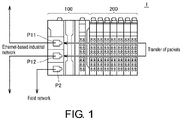
- FIG. 1 is a schematic diagram showing a configuration example of a control apparatus 1 according to the present embodiment.
- the control apparatus 1 according to the present embodiment is a programmable controller (PLC) for controlling an object under control including any facility or machine.
- the control apparatus 1 has at least one main unit 100.
- the main unit 100 is equivalent to an arithmetic processing part for executing an arbitrary program for controlling the object under control and, as described later, also has a communication function for exchanging data with another apparatus.
- the control apparatus 1 includes a local unit 200 connected to the main unit 100 via a local bus.
- the local unit 200 is assumed to be an input/output unit for exchanging signals with the field, a safety control unit in charge of safety control, a special control unit in charge of PID (Proportional Integral Derivative) control, robot control, etc.
- PID Proportional Integral Derivative
- the main unit 100 has three communication ports P11, P12, P2.
- the communication ports P11 and P12 are capable of exchanging data under the same communication protocol.
- the communication ports P11, P12 are connected to an Ethernet-based industrial network.
- the communication port P2 exchanges data with a field apparatus, such as a remote input/output device, various sensors, various actuators, etc.
- a field apparatus such as a remote input/output device, various sensors, various actuators, etc.
- the communication port P2 is connected to a field network. Also, the communication port P2 may be omitted.
- control apparatus 1 packets can be arbitrarily transferred between the communication port P11 and the communication port P12. That is, the control apparatus 1 has a packet transfer function for outputting a duplicate of a packet received by the communication port P11 from the communication port P12 and outputting a duplicate of a packet received by the communication port P12 from the communication port P11.
- various network functions e.g., a repeater hub function, a switching hub function, a router function, a filtering function, a packet monitoring function, etc., as described later
- various network functions e.g., a repeater hub function, a switching hub function, a router function, a filtering function, a packet monitoring function, etc., as described later
- the configuration of network connection can be simplified even in a case where a plurality of control apparatuses are in network connection.
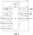
- FIG. 2 is a schematic diagram showing a configuration example of the main unit 100 included in the control apparatus 1 according to the present embodiment.
- the main unit 100 includes a processor 102, a chipset 104, a main memory apparatus 106, a secondary memory apparatus 108, network controller 110, network controller 120, a field network controller 130, a universal serial bus (USB) controller 140, a memory card interface 150, and a local bus controller 160.
- a processor 102 includes a processor 102, a chipset 104, a main memory apparatus 106, a secondary memory apparatus 108, network controller 110, network controller 120, a field network controller 130, a universal serial bus (USB) controller 140, a memory card interface 150, and a local bus controller 160.
- USB universal serial bus
- the processor 102 is equivalent to the arithmetic processing part that executes control computation, etc., and is configured with a central processing unit (CPU), a graphics processing unit (GPU), etc.
- the processor 102 reads a program (e.g., a system program or a user program) stored in the secondary memory apparatus 108, develops the program in the main memory apparatus 106, and executes the program, thereby realizing control corresponding to the object under control as well as various processes to be described later.
- a program e.g., a system program or a user program
- the chipset 104 mediates and controls data exchange between components constituting the main unit 100.
- the main memory apparatus 106 is composed of a volatile memory apparatus, such as a dynamic random access memory (DRAM) or a static random access memory (SRAM).
- the secondary memory apparatus 108 is composed of, for example, a non-volatile memory apparatus, such as a hard disk drive (HDD) or a solid state drive (SSD).
- HDD hard disk drive
- SSD solid state drive
- the network controllers 110, 120 exchange data with another control apparatus or an arbitrary device via respective networks according to a communication protocol for industrial use.
- the network controllers 110, 120 are compatible with an Ethernet-based industrial network and have the functions of a physical layer and a data link layer conforming to the specification of the Ethernet.
- a communication protocol such as the transmission control protocol/Internet protocol (TCP/IP) or the user datagram protocol/Internet protocol (UDP/IP) may be used.
- TCP/IP transmission control protocol/Internet protocol
- UDP/IP user datagram protocol/Internet protocol
- a communication protocol including the Ethernet and TCP/IP may be adopted as the communication protocol used for data exchange by the network controllers 110, 120.
- an industrial network such as EtherNet/IP, DeviceNet, ControlNet, CompoNet, etc., can be realized.
- the network controllers 110, 120 can function as a kind of switching hub or repeater hub. That is, packets being transmitted and received can be transferred internally between the network controller 110 and the network controller 120, a duplicate of the packet received by the network controller 110 can be transmitted from the network controller 120, and a duplicate of the packet received by the network controller 120 can also be transmitted from the network controller 110.
- the field network controller 130 is compatible with a communication protocol different from the communication protocol used in the network controllers 110, 120. That is, the field network controller 130 exchanges data with an arbitrary device via a field network according to a communication protocol for the field network.
- a communication protocol of an industrial network that guarantees arrival time of data may be adopted.
- the field network controller 130 one conforming to any of EtherCAT (registered trademark), DeviceNet (registered trademark), CompoNet (registered trademark), PROFIBUS (registered trademark), etc., may be adopted.
- the USB controller 140 exchanges data with a support apparatus not shown herein, etc., via a USB connection.
- a memory card 152 which is an example of a recording medium can be attached and removed.
- the memory card interface 150 can read and write various data (user program, setting data, log, trace data, etc.) with the memory card 152.
- the local bus controller 160 exchanges data with the local unit 200 (see FIG. 1 ), etc., via the local bus.
- FIG. 2 shows a configuration example in which necessary functions are provided by the processor 102 executing the program.
- a dedicated hardware circuit e.g., an application specific integrated circuit (ASIC), a field-programmable gate array (FPGA), etc.
- the main part of the main unit 100 may be realized by using hardware conforming to a general-purpose architecture (e.g., an industrial personal computer based on a general-purpose personal computer).
- a virtualization technique a plurality of operating systems (OSs) having different uses may be executed in parallel, and necessary applications may be executed on the respective OSs.
- OSs operating systems
- a configuration in which functions such as a display apparatus, a support apparatus, etc., are integrated in the main unit 100 may be adopted.
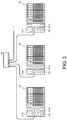
- FIG. 3 is a schematic diagram showing a general mode of hub connection.
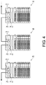
- FIG. 4 is a schematic diagram showing a connection configuration similar to a daisy chain.
- FIGs. 3 and 4 show examples in which three control apparatuses 1A to 1C are connected to each other.
- the plurality of control apparatuses 1 are connected around a hub 10. More specifically, the communication port P11 of the control apparatus 1A is connected to one communication port of the hub 10, the communication port P11 of the control apparatus 1B is connected to another communication port of the hub 10, and the communication port P11 of the control apparatus 1C is connected to still another communication port of the hub 10.
- the plurality of control apparatuses 1 are connected in series like a daisy chain. More specifically, the communication port P12 of the control apparatus 1A and the communication port P11 of the control apparatus 1B are connected, and the communication port P12 of the control apparatus 1B and the communication port P11 of the control apparatus 1C are connected.
- the communication port P11 of the control apparatus 1A may be connected to another control apparatus 1, and the communication port P12 of the control apparatus 1C may be connected to another control apparatus 1.
- the communication port P11 and the communication port P12 of each control apparatus 1 function as a repeater hub or a switching hub. That is, a packet entering the communication port P11 of a certain control apparatus 1 is transmitted as-is or selectively from the communication port P12. Likewise, a packet entering the communication port P12 of a certain control apparatus 1 is transmitted as-is or selectively from the communication port P11.
- the hub 10 as shown in FIG. 3 can be eliminated.
- control apparatuses 1 are in network connection.
- any arbitrary device can be connected to the network without being limited to the control apparatuses 1.
- the control apparatus 1 has a packet transfer function for outputting a duplicate of a packet received by the network controller 110 (the communication port P11) from the network controller 120 (the communication port P12) and outputting a duplicate of a packet received by the network controller 120 (the communication port P12) from the network controller 110 (the communication port P11).
- a packet transfer function for outputting a duplicate of a packet received by the network controller 110 (the communication port P11) from the network controller 120 (the communication port P12) and outputting a duplicate of a packet received by the network controller 120 (the communication port P12) from the network controller 110 (the communication port P11).
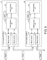
- FIG. 5 is a schematic diagram showing a functional configuration in a case where the repeater hub function is implemented in the control apparatus 1 according to the present embodiment.
- each of the control apparatuses 1A, 1B includes a packet duplicating part 170 and a packet processing part 180 in addition to the network controllers 110, 120.
- the packet duplicating part 170 and the packet processing part 180 may typically be implemented by the processor 102 executing a system program, etc. It may also be that part or all of the functions provided by the packet duplicating part 170 and the packet processing part 180 are implemented by using a dedicated hardware circuit, such as an ASIC, an FPGA, etc.
- the packet duplicating part 170 duplicates an arbitrary packet received by one of the network controllers 110, 120 and outputs the packet to one of the network controllers 110, 120. Also, the packet duplicating part 170 outputs the packet received by one of the network controllers 110, 120 to the packet processing part 180.
- the packet processing part 180 executes a process in correspondence with the packet given from the packet duplicating part 170.
- the packet duplicating part 170 transmits a packet entering one of the network controllers as-is from the other network controller. As shown in FIG. 5 , for example, when a packet 1 enters the network controller 110 of the control apparatus 1A, the packet 1 is duplicated as-is and transmitted from the network controller 120. Likewise, in the control apparatus 1B, the packet entering the network controller 110 is duplicated as-is and output from the network controller 120.
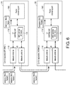
- FIG. 6 is a schematic diagram showing a functional configuration in a case where the switching hub function is implemented in the control apparatus 1 according to the present embodiment.
- each of the control apparatuses 1A, 1B includes an L2 switching part 172 and the packet processing part 180 in addition to the network controllers 110, 120.
- the L2 switching part 172 and the packet processing part 180 may be implemented by the processor 102 executing a system program, etc. It may also be that part or all of the functions provided by the L2 switching part 172 and the packet processing part 180 are implemented by using a dedicated hardware circuit, such as an ASIC, an FPGA, etc.
- the L2 switching part 172 realizes packet filtering and transfer processes at a layer 2 (L2) level. That is, based on the physical address designated as the destination of a packet received by one of the network controllers, the L2 switching part 172 determines whether to output a duplicate of the received packet from the other network controller. More specifically, the L2 switching part 172 refers to media access control (MAC) address information 173 describing the MAC address, which is the physical address of the control apparatus 1 connected to the network, and controls the transfer destination of the packet.
- the MAC address information 173 may be statically determined in advance or may be appropriately updated during the packet transfer process.
- the L2 switching part 172 determines whether the received packet is a packet addressed to its own apparatus. When determining that the received packet is a packet addressed to its own apparatus, the L2 switching part 172 outputs the received packet to the packet processing part 180. In this case, the L2 switching part 172 does not transfer the received packet to another control apparatus 1.
- the packet processing part 180 executes a process in correspondence with the packet given from the L2 switching part 172.
- the L2 switching part 172 determines whether the received packet should be transferred to another control apparatus 1. Then, when determining that the received packet should be transferred to another control apparatus 1, the L2 switching part 172 transmits a duplicate of the packet from the other network controller.
- the L2 switching part 172 filters the packet entering one of the network controllers with the MAC address and then transmits the replicate from the other network controller.
- the packet 1 addressed to MAC1 the MAC address of the control apparatus 1A
- a packet 2 addressed to MAC2 the MAC address of the control apparatus 1B
- the L2 switching part 172 outputs the packet 1 addressed to its own apparatus to the packet processing part 180, and does not transfer the packet 1 to another control apparatus 1.
- the L2 switching part 172 replicates the packet 2 that is addressed to the control apparatus 1B but not to its own apparatus, and transmits it from the network controller 120.
- the packet communication substantially the same as the case where the plurality of control apparatuses 1 are connected to a common switching hub can be realized.
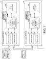
- FIG. 7 is a schematic diagram showing a functional configuration when the router function is implemented in the control apparatus 1 according to the present embodiment.
- each of the control apparatuses 1A, 1B includes an L3 switching part 174 and the packet processing part 180 in addition to the network controllers 110, 120.
- the L3 switching part 174 and the packet processing part 180 may be implemented by the processor 102 executing a system program, etc. It may also be that part or all of the functions provided by the L3 switching part 174 and the packet processing part 180 are implemented by using a dedicated hardware circuit, such as an ASIC, an FPGA, etc.
- the L3 switching part 174 realizes packet filtering and transfer processes at a layer 3 (L3) level. That is, based on the network address designated as the destination of a packet received by one of the network controllers, the L3 switching part 174 determines whether to output a duplicate of the received packet from the other network controller. More specifically, the L3 switching part 174 refers to IP (Internet protocol) address information 175 in which the IP address as the network address of the control apparatus 1 connected to the network is described, and controls the transfer destination of the packet.
- IP address information 175 may be statically determined in advance or may be appropriately updated during the packet transfer process.
- the L3 switching part 174 determines whether the received packet is a packet addressed to its own apparatus. When determining that the received packet is a packet addressed to its own apparatus, the L3 switching part 174 outputs the received packet to the packet processing part 180. In this case, the L3 switching part 174 does not forward the received packet to another control apparatus 1.
- the packet processing part 180 executes a process in correspondence with the packet given from the L3 switching part 174.
- the L3 switching part 174 determines whether the received packet should be transmitted to another control apparatus 1. Then, when determining that the received packet should be transmitted to another control apparatus 1, the L3 switching part 174 transmits a duplicate of the packet from the other network controller.
- the L3 switching part 174 filters the packet entering one of the network controllers with the IP address, and then transmits the replicate from the other network controller.
- the packet 1 addressed to IP1 the IP address of the control apparatus 1A
- the packet 2 addressed to IP2 the IP address of the control apparatus 1B
- the L3 switching part 174 outputs the packet 1 addressed to its own process to the packet processing part 180, and does not transmit the packet 1 to another control apparatus 1.
- the L3 switching part 174 replicates the packet 2 that is addressed to the control apparatus 1B but not to its own apparatus, and transmits it from the network controller 120.
- the packet communication substantially the same as the case where the plurality of control apparatuses 1 are connected to a common router or bridge can be realized.
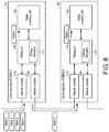
- FIG. 8 is a schematic diagram showing a functional configuration in a case where the filtering function is implemented in the control apparatus 1 according to the present embodiment.
- each of the control apparatuses 1A, 1B includes a filtering part 176 and the packet processing part 180 in addition to the network controllers 110, 120.
- the filtering part 176 and the packet processing part 180 are typically implemented by the processor 102 executing a system program, etc. It may also be that part or all of the functions provided by the filtering part 176 and the packet processing part 180 are implemented by using a dedicated hardware circuit, such as an ASIC, an FPGA, etc.
- the filtering part 176 manages the transfer to the next control apparatus 1. More specifically, the filtering part 176 refers to filtering information 177 describing a transfer condition of the packet and determines whether the packet received by one of the network controllers 110, 120 is to be transferred and whether the transfer is necessary.
- the filtering information 177 may be defined in the form of a whitelist describing a condition under which the packet should be transferred or in the form of a blacklist describing a condition under which the packet that should not be transferred.
- the filtering information 177 may be arbitrarily set or updated externally.
- the filtering part 176 refers to the filtering information 177 and determines whether the received packet should be received or transferred based on the header information, etc., in the received packet. A packet that is determined not to be received or transferred may be discarded.
- the filtering part 176 outputs a packet addressed to its own apparatus, among the packets determined to be received or transferred, to the packet processing part 180. In this case, the filtering part 176 does not transmit the received packet to another control apparatus 1. Also, regarding a packet addressed to another control apparatus 1 among the packets determined to be received or transferred, the filtering part 176 sends a duplicate of the packet from the other network controller.
- the filtering part 176 filters the packet entering one of network controllers under an arbitrary filtering condition and then sends the replicate from the other network controller as needed.
- the packet 1 is a transferable packet directed to the control apparatus 1A
- the packet 2 is a transferable packet directed to the control apparatus 1B
- the packets 3 and 4 are packets that cannot be transferred.
- the filtering part 176 discards the packet 3 and the packet 4, and processes only the packet 1 and the packet 2 as valid ones.
- the packet 1 is given to the packet processing part 180 of the control apparatus 1A
- the packet 2 is given to the packet processing part 180 of the control apparatus 1B.
- the control apparatus 1 can duplicate a packet received by one of the network controllers 110, 120 and transmit it from the other of the network controllers 110, 120.
- a packet monitoring function may be realized by utilizing the process of duplicating the packet from the one of the network controllers to the other network controller.
- the packet monitoring function is a function for sequentially collecting the history of the packet transmitted on the network and can be used for investigating the cause of any trouble occurring in the network.
- the beginning and the end of packet history collection can be arbitrarily designated.
- arbitrary filtering on packets to be collected may be performed. For example, filtering such as only packets transmitted from a specific control apparatus 1 or only packets having a specific port number can be performed.
- an instruction designating the network function that should be enabled may be described in the user program executed in the control apparatus 1. In this case, by activating the control apparatus 1 and executing the user program, the designated network function is activated.
- a function block corresponding to each network function may be provided as an instruction for activating such a network function.
- the program creator can realize the necessary network function even if the program creator has limited network-related knowledge.
- the main unit 100 and the support apparatus are configured to be independent from each other.
- all or part of the functions of the support apparatus may be incorporated into the main unit 100.
- a process equivalent to the control apparatus 1 and a process equivalent to the support apparatus may be executed in parallel on common hardware.
- the control apparatus 1 including the main unit 100 and the local unit 200 is exemplified.
- a configuration in which a safety control unit, a special control unit, etc., is mounted on a local bus from the main unit 100 may be adopted.
- the mounted safe control unit or special control unit can also establish connection with another unit or device by using the network controllers 110, 120 of the main unit 100.
- the network functions as described above can be applied.
- a control apparatus (1) for controlling an object under control including:
- the control apparatus according to Configuration 1, wherein the first communication protocol is a communication protocol including Ethernet (registered trademark) and TCP/IP.
- control apparatus according to Configuration 1 or 2, further including a third network controller for exchanging data according to a second communication protocol different from the first communication protocol.
- the control apparatus according to Configuration 3, wherein the second communication protocol is a communication protocol of an industrial network that guarantees arrival time of data.
- the packet transferring part (172) determines whether to output a duplicate of the received packet from another network controller.
- the packet transferring part (174) determines whether to output a duplicate of the received packet from another network controller.
- the control apparatus 1 has two network controllers, and can arbitrarily transfer packets between the network controllers, and implements a network function which uses such a packet transfer function.
- the configuration of network connection can be simplified even when multiple control apparatuses are in network connection.
Landscapes
- Engineering & Computer Science (AREA)
- Signal Processing (AREA)
- Computer Networks & Wireless Communication (AREA)
- Quality & Reliability (AREA)
- Physics & Mathematics (AREA)
- General Physics & Mathematics (AREA)
- Automation & Control Theory (AREA)
- Manufacturing & Machinery (AREA)
- General Engineering & Computer Science (AREA)
- Computer Security & Cryptography (AREA)
- Small-Scale Networks (AREA)
- Programmable Controllers (AREA)
- Data Exchanges In Wide-Area Networks (AREA)
Applications Claiming Priority (1)
| Application Number | Priority Date | Filing Date | Title |
|---|---|---|---|
| JP2018068198A JP6988650B2 (ja) | 2018-03-30 | 2018-03-30 | 制御装置 |
Publications (2)
| Publication Number | Publication Date |
|---|---|
| EP3547055A1 true EP3547055A1 (fr) | 2019-10-02 |
| EP3547055B1 EP3547055B1 (fr) | 2022-10-19 |
Family
ID=65411755
Family Applications (1)
| Application Number | Title | Priority Date | Filing Date |
|---|---|---|---|
| EP19156385.7A Active EP3547055B1 (fr) | 2018-03-30 | 2019-02-11 | Appareil de commande |
Country Status (4)
| Country | Link |
|---|---|
| US (1) | US20190305977A1 (fr) |
| EP (1) | EP3547055B1 (fr) |
| JP (1) | JP6988650B2 (fr) |
| CN (1) | CN110320868A (fr) |
Families Citing this family (2)
| Publication number | Priority date | Publication date | Assignee | Title |
|---|---|---|---|---|
| CN112953800B (zh) * | 2019-11-26 | 2022-10-04 | 台达电子工业股份有限公司 | 基于EtherCAT协定的数据交握方法 |
| JP7826061B2 (ja) * | 2022-03-04 | 2026-03-09 | ニデックインスツルメンツ株式会社 | データ収集ユニット及びロボットコントローラ |
Citations (5)
| Publication number | Priority date | Publication date | Assignee | Title |
|---|---|---|---|---|
| EP1760563A1 (fr) * | 2005-08-31 | 2007-03-07 | Omron Corporation | Système de communication et unités esclave et de répétition de celui-ci |
| JP2008084343A (ja) | 2007-12-17 | 2008-04-10 | Omron Corp | プログラマブルコントローラおよび通信ユニット |
| US20080298365A1 (en) * | 2007-05-30 | 2008-12-04 | Jujitsu Limited | Packet relay method and device |
| US20120263178A1 (en) * | 2002-07-10 | 2012-10-18 | Juniper Networks, Inc. | Systems and methods for efficient multicast handling |
| EP2797265A1 (fr) * | 2012-01-27 | 2014-10-29 | Omron Corporation | Dispositif de relais de données, dispositif de transmission de données et système de réseau |
Family Cites Families (3)
| Publication number | Priority date | Publication date | Assignee | Title |
|---|---|---|---|---|
| US8428054B2 (en) * | 2005-11-14 | 2013-04-23 | Lantronix, Inc. | Daisy chaining device servers via ethernet |
| US10397850B2 (en) * | 2015-04-30 | 2019-08-27 | Lg Electronics Inc. | Method and device for transmitting/receiving data in mesh network using bluetooth |
| US11333810B2 (en) * | 2017-08-25 | 2022-05-17 | Solutia Canada Inc. | System of networked controllers, and method of operating a system of networked controllers |
-
2018
- 2018-03-30 JP JP2018068198A patent/JP6988650B2/ja active Active
-
2019
- 2019-02-11 EP EP19156385.7A patent/EP3547055B1/fr active Active
- 2019-02-12 CN CN201910110701.3A patent/CN110320868A/zh active Pending
- 2019-02-14 US US16/275,353 patent/US20190305977A1/en not_active Abandoned
Patent Citations (5)
| Publication number | Priority date | Publication date | Assignee | Title |
|---|---|---|---|---|
| US20120263178A1 (en) * | 2002-07-10 | 2012-10-18 | Juniper Networks, Inc. | Systems and methods for efficient multicast handling |
| EP1760563A1 (fr) * | 2005-08-31 | 2007-03-07 | Omron Corporation | Système de communication et unités esclave et de répétition de celui-ci |
| US20080298365A1 (en) * | 2007-05-30 | 2008-12-04 | Jujitsu Limited | Packet relay method and device |
| JP2008084343A (ja) | 2007-12-17 | 2008-04-10 | Omron Corp | プログラマブルコントローラおよび通信ユニット |
| EP2797265A1 (fr) * | 2012-01-27 | 2014-10-29 | Omron Corporation | Dispositif de relais de données, dispositif de transmission de données et système de réseau |
Also Published As
| Publication number | Publication date |
|---|---|
| JP6988650B2 (ja) | 2022-01-05 |
| US20190305977A1 (en) | 2019-10-03 |
| EP3547055B1 (fr) | 2022-10-19 |
| JP2019180019A (ja) | 2019-10-17 |
| CN110320868A (zh) | 2019-10-11 |
Similar Documents
| Publication | Publication Date | Title |
|---|---|---|
| US9088558B2 (en) | Secure one-way interface for OPC data transfer | |
| US11012256B2 (en) | Connection unit, monitoring system and method for operating an automation system | |
| US8990444B2 (en) | Fieldbus gateway using virtual serial fieldbus port and data transmission method thereof | |
| US20170155717A1 (en) | Direct memory access for endpoint devices | |
| US9021167B2 (en) | Method and a bus device for transmitting safety-oriented data | |
| CN110320829B (zh) | 安全控制系统以及安全控制单元 | |
| JP6747525B2 (ja) | セーフティシステムおよびセーフティコントローラ | |
| EP3764175B1 (fr) | Dispositif de commande et système de commande | |
| US20200220846A1 (en) | Automation and/or Communications Appliance and Method for Checking Datagrams Transmitted in An Industrial Automation System | |
| EP3547055A1 (fr) | Appareil de commande | |
| US10374834B2 (en) | Modular industrial automation appliance and method for transmitting messages via a backplane bus system of the modular industrial automation appliance | |
| US11226611B2 (en) | Control device, control method, and control program | |
| Seno et al. | A simulation approach to a Real-Time Ethernet protocol: EtherCAT | |
| US20020156868A1 (en) | Industrial control system with Web enabled I/O modules | |
| CN115396135B (zh) | 控制装置、记录方法以及记录有程序的记录介质 | |
| CN202856779U (zh) | 用于自动化网络的网络设备,安全模块和自动化网络 | |
| JP6915583B2 (ja) | セーフティ制御システムおよびセーフティ制御システムにおける制御方法 | |
| JP2006171833A (ja) | Plcのデータ交換システム、及びplcのデータ交換システムの制御方法 | |
| EP4210283A1 (fr) | Système de commande et/ou de surveillance pour les applications ethernet industrielles et procédé correspondant de commande et de surveillance d'un dispositif ethernet industriel | |
| KR20190062214A (ko) | 통신 제어 장치 | |
| KR20250064141A (ko) | 내부망 주도하에 외부망과의 통신을 통제하는 tcp/ip 망단절형 단방향 접속 시스템 | |
| Antoniou | The Operation and Cyber Security of Industrial Control Systems and Industrial Communication Protocols: An Exploratory Approach | |
| Kuchen | TELECONTROL SYSTEM BASED ON TCP/IP | |
| WO2018109949A1 (fr) | Dispositif de simulation, procédé de simulation et programme de simulation |
Legal Events
| Date | Code | Title | Description |
|---|---|---|---|
| PUAI | Public reference made under article 153(3) epc to a published international application that has entered the european phase |
Free format text: ORIGINAL CODE: 0009012 |
|
| STAA | Information on the status of an ep patent application or granted ep patent |
Free format text: STATUS: REQUEST FOR EXAMINATION WAS MADE |
|
| 17P | Request for examination filed |
Effective date: 20190306 |
|
| AK | Designated contracting states |
Kind code of ref document: A1 Designated state(s): AL AT BE BG CH CY CZ DE DK EE ES FI FR GB GR HR HU IE IS IT LI LT LU LV MC MK MT NL NO PL PT RO RS SE SI SK SM TR |
|
| AX | Request for extension of the european patent |
Extension state: BA ME |
|
| RBV | Designated contracting states (corrected) |
Designated state(s): AL AT BE BG CH CY CZ DE DK EE ES FI FR GB GR HR HU IE IS IT LI LT LU LV MC MK MT NL NO PL PT RO RS SE SI SK SM TR |
|
| STAA | Information on the status of an ep patent application or granted ep patent |
Free format text: STATUS: EXAMINATION IS IN PROGRESS |
|
| 17Q | First examination report despatched |
Effective date: 20210209 |
|
| GRAP | Despatch of communication of intention to grant a patent |
Free format text: ORIGINAL CODE: EPIDOSNIGR1 |
|
| STAA | Information on the status of an ep patent application or granted ep patent |
Free format text: STATUS: GRANT OF PATENT IS INTENDED |
|
| INTG | Intention to grant announced |
Effective date: 20220624 |
|
| GRAS | Grant fee paid |
Free format text: ORIGINAL CODE: EPIDOSNIGR3 |
|
| GRAA | (expected) grant |
Free format text: ORIGINAL CODE: 0009210 |
|
| STAA | Information on the status of an ep patent application or granted ep patent |
Free format text: STATUS: THE PATENT HAS BEEN GRANTED |
|
| AK | Designated contracting states |
Kind code of ref document: B1 Designated state(s): AL AT BE BG CH CY CZ DE DK EE ES FI FR GB GR HR HU IE IS IT LI LT LU LV MC MK MT NL NO PL PT RO RS SE SI SK SM TR |
|
| REG | Reference to a national code |
Ref country code: GB Ref legal event code: FG4D |
|
| REG | Reference to a national code |
Ref country code: CH Ref legal event code: EP |
|
| REG | Reference to a national code |
Ref country code: IE Ref legal event code: FG4D |
|
| REG | Reference to a national code |
Ref country code: DE Ref legal event code: R096 Ref document number: 602019020694 Country of ref document: DE |
|
| REG | Reference to a national code |
Ref country code: AT Ref legal event code: REF Ref document number: 1525940 Country of ref document: AT Kind code of ref document: T Effective date: 20221115 |
|
| REG | Reference to a national code |
Ref country code: LT Ref legal event code: MG9D |
|
| REG | Reference to a national code |
Ref country code: NL Ref legal event code: MP Effective date: 20221019 |
|
| REG | Reference to a national code |
Ref country code: AT Ref legal event code: MK05 Ref document number: 1525940 Country of ref document: AT Kind code of ref document: T Effective date: 20221019 |
|
| PG25 | Lapsed in a contracting state [announced via postgrant information from national office to epo] |
Ref country code: NL Free format text: LAPSE BECAUSE OF FAILURE TO SUBMIT A TRANSLATION OF THE DESCRIPTION OR TO PAY THE FEE WITHIN THE PRESCRIBED TIME-LIMIT Effective date: 20221019 |
|
| PG25 | Lapsed in a contracting state [announced via postgrant information from national office to epo] |
Ref country code: SE Free format text: LAPSE BECAUSE OF FAILURE TO SUBMIT A TRANSLATION OF THE DESCRIPTION OR TO PAY THE FEE WITHIN THE PRESCRIBED TIME-LIMIT Effective date: 20221019 Ref country code: PT Free format text: LAPSE BECAUSE OF FAILURE TO SUBMIT A TRANSLATION OF THE DESCRIPTION OR TO PAY THE FEE WITHIN THE PRESCRIBED TIME-LIMIT Effective date: 20230220 Ref country code: NO Free format text: LAPSE BECAUSE OF FAILURE TO SUBMIT A TRANSLATION OF THE DESCRIPTION OR TO PAY THE FEE WITHIN THE PRESCRIBED TIME-LIMIT Effective date: 20230119 Ref country code: LT Free format text: LAPSE BECAUSE OF FAILURE TO SUBMIT A TRANSLATION OF THE DESCRIPTION OR TO PAY THE FEE WITHIN THE PRESCRIBED TIME-LIMIT Effective date: 20221019 Ref country code: FI Free format text: LAPSE BECAUSE OF FAILURE TO SUBMIT A TRANSLATION OF THE DESCRIPTION OR TO PAY THE FEE WITHIN THE PRESCRIBED TIME-LIMIT Effective date: 20221019 Ref country code: ES Free format text: LAPSE BECAUSE OF FAILURE TO SUBMIT A TRANSLATION OF THE DESCRIPTION OR TO PAY THE FEE WITHIN THE PRESCRIBED TIME-LIMIT Effective date: 20221019 Ref country code: AT Free format text: LAPSE BECAUSE OF FAILURE TO SUBMIT A TRANSLATION OF THE DESCRIPTION OR TO PAY THE FEE WITHIN THE PRESCRIBED TIME-LIMIT Effective date: 20221019 |
|
| PG25 | Lapsed in a contracting state [announced via postgrant information from national office to epo] |
Ref country code: RS Free format text: LAPSE BECAUSE OF FAILURE TO SUBMIT A TRANSLATION OF THE DESCRIPTION OR TO PAY THE FEE WITHIN THE PRESCRIBED TIME-LIMIT Effective date: 20221019 Ref country code: PL Free format text: LAPSE BECAUSE OF FAILURE TO SUBMIT A TRANSLATION OF THE DESCRIPTION OR TO PAY THE FEE WITHIN THE PRESCRIBED TIME-LIMIT Effective date: 20221019 Ref country code: LV Free format text: LAPSE BECAUSE OF FAILURE TO SUBMIT A TRANSLATION OF THE DESCRIPTION OR TO PAY THE FEE WITHIN THE PRESCRIBED TIME-LIMIT Effective date: 20221019 Ref country code: IS Free format text: LAPSE BECAUSE OF FAILURE TO SUBMIT A TRANSLATION OF THE DESCRIPTION OR TO PAY THE FEE WITHIN THE PRESCRIBED TIME-LIMIT Effective date: 20230219 Ref country code: HR Free format text: LAPSE BECAUSE OF FAILURE TO SUBMIT A TRANSLATION OF THE DESCRIPTION OR TO PAY THE FEE WITHIN THE PRESCRIBED TIME-LIMIT Effective date: 20221019 Ref country code: GR Free format text: LAPSE BECAUSE OF FAILURE TO SUBMIT A TRANSLATION OF THE DESCRIPTION OR TO PAY THE FEE WITHIN THE PRESCRIBED TIME-LIMIT Effective date: 20230120 |
|
| REG | Reference to a national code |
Ref country code: DE Ref legal event code: R097 Ref document number: 602019020694 Country of ref document: DE |
|
| PG25 | Lapsed in a contracting state [announced via postgrant information from national office to epo] |
Ref country code: SM Free format text: LAPSE BECAUSE OF FAILURE TO SUBMIT A TRANSLATION OF THE DESCRIPTION OR TO PAY THE FEE WITHIN THE PRESCRIBED TIME-LIMIT Effective date: 20221019 Ref country code: RO Free format text: LAPSE BECAUSE OF FAILURE TO SUBMIT A TRANSLATION OF THE DESCRIPTION OR TO PAY THE FEE WITHIN THE PRESCRIBED TIME-LIMIT Effective date: 20221019 Ref country code: EE Free format text: LAPSE BECAUSE OF FAILURE TO SUBMIT A TRANSLATION OF THE DESCRIPTION OR TO PAY THE FEE WITHIN THE PRESCRIBED TIME-LIMIT Effective date: 20221019 Ref country code: DK Free format text: LAPSE BECAUSE OF FAILURE TO SUBMIT A TRANSLATION OF THE DESCRIPTION OR TO PAY THE FEE WITHIN THE PRESCRIBED TIME-LIMIT Effective date: 20221019 Ref country code: CZ Free format text: LAPSE BECAUSE OF FAILURE TO SUBMIT A TRANSLATION OF THE DESCRIPTION OR TO PAY THE FEE WITHIN THE PRESCRIBED TIME-LIMIT Effective date: 20221019 |
|
| PLBE | No opposition filed within time limit |
Free format text: ORIGINAL CODE: 0009261 |
|
| STAA | Information on the status of an ep patent application or granted ep patent |
Free format text: STATUS: NO OPPOSITION FILED WITHIN TIME LIMIT |
|
| PG25 | Lapsed in a contracting state [announced via postgrant information from national office to epo] |
Ref country code: SK Free format text: LAPSE BECAUSE OF FAILURE TO SUBMIT A TRANSLATION OF THE DESCRIPTION OR TO PAY THE FEE WITHIN THE PRESCRIBED TIME-LIMIT Effective date: 20221019 Ref country code: AL Free format text: LAPSE BECAUSE OF FAILURE TO SUBMIT A TRANSLATION OF THE DESCRIPTION OR TO PAY THE FEE WITHIN THE PRESCRIBED TIME-LIMIT Effective date: 20221019 |
|
| 26N | No opposition filed |
Effective date: 20230720 |
|
| PG25 | Lapsed in a contracting state [announced via postgrant information from national office to epo] |
Ref country code: MC Free format text: LAPSE BECAUSE OF FAILURE TO SUBMIT A TRANSLATION OF THE DESCRIPTION OR TO PAY THE FEE WITHIN THE PRESCRIBED TIME-LIMIT Effective date: 20221019 |
|
| REG | Reference to a national code |
Ref country code: CH Ref legal event code: PL |
|
| REG | Reference to a national code |
Ref country code: BE Ref legal event code: MM Effective date: 20230228 |
|
| GBPC | Gb: european patent ceased through non-payment of renewal fee |
Effective date: 20230211 |
|
| PG25 | Lapsed in a contracting state [announced via postgrant information from national office to epo] |
Ref country code: LU Free format text: LAPSE BECAUSE OF NON-PAYMENT OF DUE FEES Effective date: 20230211 Ref country code: LI Free format text: LAPSE BECAUSE OF NON-PAYMENT OF DUE FEES Effective date: 20230228 Ref country code: CH Free format text: LAPSE BECAUSE OF NON-PAYMENT OF DUE FEES Effective date: 20230228 |
|
| PG25 | Lapsed in a contracting state [announced via postgrant information from national office to epo] |
Ref country code: SI Free format text: LAPSE BECAUSE OF FAILURE TO SUBMIT A TRANSLATION OF THE DESCRIPTION OR TO PAY THE FEE WITHIN THE PRESCRIBED TIME-LIMIT Effective date: 20221019 |
|
| REG | Reference to a national code |
Ref country code: IE Ref legal event code: MM4A |
|
| PG25 | Lapsed in a contracting state [announced via postgrant information from national office to epo] |
Ref country code: GB Free format text: LAPSE BECAUSE OF NON-PAYMENT OF DUE FEES Effective date: 20230211 |
|
| PG25 | Lapsed in a contracting state [announced via postgrant information from national office to epo] |
Ref country code: IE Free format text: LAPSE BECAUSE OF NON-PAYMENT OF DUE FEES Effective date: 20230211 Ref country code: GB Free format text: LAPSE BECAUSE OF NON-PAYMENT OF DUE FEES Effective date: 20230211 Ref country code: FR Free format text: LAPSE BECAUSE OF NON-PAYMENT OF DUE FEES Effective date: 20230228 |
|
| PG25 | Lapsed in a contracting state [announced via postgrant information from national office to epo] |
Ref country code: BE Free format text: LAPSE BECAUSE OF NON-PAYMENT OF DUE FEES Effective date: 20230228 |
|
| PG25 | Lapsed in a contracting state [announced via postgrant information from national office to epo] |
Ref country code: IT Free format text: LAPSE BECAUSE OF FAILURE TO SUBMIT A TRANSLATION OF THE DESCRIPTION OR TO PAY THE FEE WITHIN THE PRESCRIBED TIME-LIMIT Effective date: 20221019 |
|
| PG25 | Lapsed in a contracting state [announced via postgrant information from national office to epo] |
Ref country code: BG Free format text: LAPSE BECAUSE OF FAILURE TO SUBMIT A TRANSLATION OF THE DESCRIPTION OR TO PAY THE FEE WITHIN THE PRESCRIBED TIME-LIMIT Effective date: 20221019 |
|
| PG25 | Lapsed in a contracting state [announced via postgrant information from national office to epo] |
Ref country code: BG Free format text: LAPSE BECAUSE OF FAILURE TO SUBMIT A TRANSLATION OF THE DESCRIPTION OR TO PAY THE FEE WITHIN THE PRESCRIBED TIME-LIMIT Effective date: 20221019 |
|
| PG25 | Lapsed in a contracting state [announced via postgrant information from national office to epo] |
Ref country code: CY Free format text: LAPSE BECAUSE OF FAILURE TO SUBMIT A TRANSLATION OF THE DESCRIPTION OR TO PAY THE FEE WITHIN THE PRESCRIBED TIME-LIMIT; INVALID AB INITIO Effective date: 20190211 |
|
| PG25 | Lapsed in a contracting state [announced via postgrant information from national office to epo] |
Ref country code: HU Free format text: LAPSE BECAUSE OF FAILURE TO SUBMIT A TRANSLATION OF THE DESCRIPTION OR TO PAY THE FEE WITHIN THE PRESCRIBED TIME-LIMIT; INVALID AB INITIO Effective date: 20190211 |
|
| PG25 | Lapsed in a contracting state [announced via postgrant information from national office to epo] |
Ref country code: TR Free format text: LAPSE BECAUSE OF FAILURE TO SUBMIT A TRANSLATION OF THE DESCRIPTION OR TO PAY THE FEE WITHIN THE PRESCRIBED TIME-LIMIT Effective date: 20221019 |
|
| PGFP | Annual fee paid to national office [announced via postgrant information from national office to epo] |
Ref country code: DE Payment date: 20260217 Year of fee payment: 8 |