EP3547068A1 - Dispositif de commande de prédiction d'état et procédé de commande de prédiction d'état - Google Patents
Dispositif de commande de prédiction d'état et procédé de commande de prédiction d'état Download PDFInfo
- Publication number
- EP3547068A1 EP3547068A1 EP17912304.7A EP17912304A EP3547068A1 EP 3547068 A1 EP3547068 A1 EP 3547068A1 EP 17912304 A EP17912304 A EP 17912304A EP 3547068 A1 EP3547068 A1 EP 3547068A1
- Authority
- EP
- European Patent Office
- Prior art keywords
- state
- prediction
- observation
- objective
- dictionary
- Prior art date
- Legal status (The legal status is an assumption and is not a legal conclusion. Google has not performed a legal analysis and makes no representation as to the accuracy of the status listed.)
- Withdrawn
Links
Images


Classifications
-
- G—PHYSICS
- G05—CONTROLLING; REGULATING
- G05B—CONTROL OR REGULATING SYSTEMS IN GENERAL; FUNCTIONAL ELEMENTS OF SUCH SYSTEMS; MONITORING OR TESTING ARRANGEMENTS FOR SUCH SYSTEMS OR ELEMENTS
- G05B13/00—Adaptive control systems, i.e. systems automatically adjusting themselves to have a performance which is optimum according to some preassigned criterion
- G05B13/02—Adaptive control systems, i.e. systems automatically adjusting themselves to have a performance which is optimum according to some preassigned criterion electric
- G05B13/04—Adaptive control systems, i.e. systems automatically adjusting themselves to have a performance which is optimum according to some preassigned criterion electric involving the use of models or simulators
- G05B13/048—Adaptive control systems, i.e. systems automatically adjusting themselves to have a performance which is optimum according to some preassigned criterion electric involving the use of models or simulators using a predictor
-
- H—ELECTRICITY
- H04—ELECTRIC COMMUNICATION TECHNIQUE
- H04N—PICTORIAL COMMUNICATION, e.g. TELEVISION
- H04N19/00—Methods or arrangements for coding, decoding, compressing or decompressing digital video signals
- H04N19/10—Methods or arrangements for coding, decoding, compressing or decompressing digital video signals using adaptive coding
- H04N19/102—Methods or arrangements for coding, decoding, compressing or decompressing digital video signals using adaptive coding characterised by the element, parameter or selection affected or controlled by the adaptive coding
- H04N19/103—Selection of coding mode or of prediction mode
- H04N19/11—Selection of coding mode or of prediction mode among a plurality of spatial predictive coding modes
-
- A—HUMAN NECESSITIES
- A01—AGRICULTURE; FORESTRY; ANIMAL HUSBANDRY; HUNTING; TRAPPING; FISHING
- A01G—HORTICULTURE; CULTIVATION OF VEGETABLES, FLOWERS, RICE, FRUIT, VINES, HOPS OR SEAWEED; FORESTRY; WATERING
- A01G7/00—Botany in general
-
- G—PHYSICS
- G06—COMPUTING OR CALCULATING; COUNTING
- G06T—IMAGE DATA PROCESSING OR GENERATION, IN GENERAL
- G06T7/00—Image analysis
-
- H—ELECTRICITY
- H04—ELECTRIC COMMUNICATION TECHNIQUE
- H04N—PICTORIAL COMMUNICATION, e.g. TELEVISION
- H04N19/00—Methods or arrangements for coding, decoding, compressing or decompressing digital video signals
- H04N19/10—Methods or arrangements for coding, decoding, compressing or decompressing digital video signals using adaptive coding
- H04N19/102—Methods or arrangements for coding, decoding, compressing or decompressing digital video signals using adaptive coding characterised by the element, parameter or selection affected or controlled by the adaptive coding
- H04N19/124—Quantisation
Definitions
- the present invention relates to a state prediction control apparatus and a state prediction control method, and relates particularly to a technology which predicts change in the state of an observation object based on an output from an observation sensor.
- Patent Literature 1 discloses a technology which estimates the physical quantity of an object based on captured image by a particle filter method and estimates the position of an object by a condensation method by taking a quantity related to the feature quantity of the object as a weight.
- Patent Literature 2 discloses a technology in which a three-dimensional model comprised of plural feature points with three-dimensional coordinate values and partial image information representing a partial image related to each feature point is projected into a two-dimensional observation space, the state quantity of the three-dimensional model is estimated using a feature point set selected in the two-dimensional observation space, the estimated three-dimensional model state is projected into the observation space, and the adaptability is repeatedly calculated to estimate the state quantity of the three-dimensional model.
- Patent Literature 3 an area of interest for determining the presence of a target is sequentially set in plural positions in an image, a reference position of a part of a case when it is assumed that a target is present in the area of interest is set based on a deformable part model, and a deformation cost that is a value representing the degree of deviation from the reference position is calculated for each of detected parts. Then, such technology is proposed in which, on the condition that plural parts of a same kind whose calculated deformation costs are within a prescribed range are present, the area of interest is determined to be a target area where a target constituting a group is present.
- Patent Literatures 1, 2, and 3 there is a problem that, even though the position and state of an object could be predicted, positive working for making the object close to the target cannot be effected when the object deviates from a future target value.
- the present invention has been achieved to solve the problem described above, and its object is to provide a technology for predicting the state of an observation object and making the state prediction close to a target value.
- An aspect of a state prediction control apparatus related to the present invention is characterized to include, a sensor information acquisition section that acquires first sensor information obtained by observing a state of an observation object at a first clock time by an observation sensor, a model dictionary storage section that stores a model dictionary that relates the kind of the observation sensor and an observation object that is determined directly from an output of the observation sensor; an object identification section that refers to the model dictionary and identifies the kind of the observation object based on the first sensor information; an objective and target dictionary storage section that stores an objective and target dictionary that defines an objective of the observation object and a target parameter for achieving the objective; a state series dictionary storage section that stores a state series dictionary that defines a series of plural state changes accompanying a lapse of time corresponding to the kind of the observation object; a state prediction section that reads a state series that defines a different state of a different clock time of the identified observation object by plural numbers from the state series dictionary, reads an
- object means one that is directly observed from sensor information outputted by each of the observation sensors.
- a crop or a growth condition
- the object is the temperature in the case of a temperature sensor
- the object is the light quantity in the case of a light quantity sensor
- the object is water supply value in the case of a water supply quantity sensor.
- a control object will be growth of a crop
- a control parameter(s) is (are) at least one of growth quantity of crop, water supply quantity, room temperature, humidity, light quantity, and fertilizer supply quantity.
- sprouting, development, flowering, fruition, and ripeness for example are made a (state) mode, and the target value in each mode is made objective information.
- the image of the crop observed by a CMOS sensor since the image of the crop observed by a CMOS sensor, the light quantity observed by a light quantity sensor, the temperature observed by a temperature sensor, and the water quantity observed by a water quantity sensor become the objects, these objects are observed, and the change is predicted.
- control is executed so as to trace not only the change speed and the change acceleration of the observed value but also a target for accomplishing an objective.
- Fig. 1 is a hardware configuration diagram of a state prediction control apparatus according to the present embodiment.
- a state prediction control apparatus 10 according to the present embodiment is configured as a computer in which each of a CPU 14 that executes a calculation process for predicting the state change of an object, a ROM 16 and a RAM 18 as a data storage device, a file unit 20 (the file unit may be configured of an HDD for example), an external interface (I/F) 22, and a monitor 24 are connected to each other through a bus 26, and are connected so as to be capable of transmitting and receiving commands and data.
- the state prediction control apparatus 10 includes in addition to the configuration described above, a number of constituent elements of the electrical system such as a power supply unit. It is noted that since they are widely known or general, detailed explanation will be omitted.
- observation sensors 30 is connected to the external I/F 22.
- the observation sensor 30 is a sensor for acquiring state information of an object that is a control object of the state prediction control apparatus 10.
- the observation sensor 30 there are a CMOS sensor 301, a light quantity sensor 302, a temperature sensor 303, a humidity sensor 304, a water supply quantity sensor 305, and a fertilizer supply quantity sensor 306 for example.
- a control unit 40 is connected to the external I/F 22.
- the control unit 40 is a device that generates an environment affecting the state change of the growth of the crop.
- the control unit 40 there are lighting 401, a heater 402, a humidifying-dehumidifying device 403, a water supply valve 404, and a fertilizer supply nozzle 405.
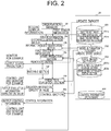
- Fig. 2 is a functional block diagram that shows a configuration of a state prediction control program executed in the state prediction control apparatus 10.
- the state prediction control apparatus 10 includes a sensor information acquisition section 14a, an object identification section 14b, a state prediction section 14c, a prediction evaluation section 14d, a control section 14e, and a matching section 14f.
- a sensor information acquisition section 14a an object identification section 14b
- a state prediction section 14c a prediction evaluation section 14d
- a control section 14e a control section 14e
- a matching section 14f a matching section 14f.
- the file unit 20 includes an objective and target dictionary 201, a model information dictionary 202 that defines a model corresponding to the kind of an object on which state prediction is executed, a state series dictionary 203 that defines a series of plural state changes accompanying the lapse of time of a model, and a control parameter dictionary 204.
- the objective and target dictionary 201 includes an objective and target dictionary storage section 201a that stores objective and target dictionary data, and an objective and target dictionary editing section 201b that edits the objective and target dictionary data.
- the state series dictionary 203 includes a state series dictionary storage section 203a that stores state series dictionary data, and a state series dictionary editing section 203b that edits the state series dictionary data. Editing mentioned here includes both of updating and deletion of the dictionary data.
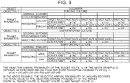
- FIG. 3 an example of an objective and target dictionary is shown.
- the kind of the object and its objective, and the parameter for achieving the objective are stored.
- forcing culture of the cucumber as the objective 1
- three phases of seeding, settled planting, and harvesting which show the growth process and the time of each phase as the target parameter for achieving the forcing culture of the cucumber.
- the target parameters where the harvest time is "January” and "February" are defined.
- the objective and target dictionary has an objective that the harvesting efficiency of a crop observed by the CMOS sensor is made as high as possible (high profit and low cost) under a certain precondition (growth start time, harvest time, cultivar, and the like).
- the target (value) is narrowed with respect to the growth condition of a crop observed by the CMOS sensor.
- the target corresponding to an objective is obtained by organizing the growth record data of the past as a dictionary which is the objective and target dictionary.
- the objective and target dictionary may be given as data in which the target (value) is tabulated with respect to the objective (value).
- the objective and the target of an object When the objective and the target of an object are given beforehand, they may be organized as a dictionary.
- the evaluation reference of an object is given and the objective value and the target value are obtained by calculation and the like from observation values obtained by observation and the like of the object, the objective value and the target value may be organized as a dictionary.
- an observation value to which a highest evaluation point is given is made an objective value and a target value which may be organized as a dictionary, or otherwise when an evaluation reference of an object is given, an objective value and a target value are obtained by calculation and the like from observation values obtained by observation and the like of the object, an observation value that has become a highest evaluation reference is made an objective value and a target value which may be also organized as a dictionary.
- the target (value) toward the objective (value) there are appropriate target values with respect to the light quantity, temperature, and water quantity.
- the appropriate target values of the light quantity, temperature, and water quantity are narrowed when it is aimed to increase the harvesting efficiency of the crop in question as much as possible.
- the objective (value) of the light quantity, temperature, and water quantity in cultivation of a crop is to increase the harvesting efficiency of a crop as much as possible, the target corresponding to this objective becomes one obtained by organizing record data in cultivating a crop in the past as a dictionary. This is the objective and target dictionary of the light quantity, temperature, and water quantity.
- the target (value) of the light quantity, temperature, and water quantity is tabulated with respect to the objective (value).
- a route (combination of the target (value)) of the light quantity, temperature, and water quantity from a certain precondition to an objective of increasing the harvesting efficiency as much as possible is not considered to be one route only. Because of the combination of the light quantity, temperature, and water quantity, the route is considered to increase to a number of possibilities; however, a number of such routes come to be recorded naturally by organizing growth record data of the past as a dictionary. When similar targets (values) are recorded, the target (value) is counted and becomes frequency data. The prediction value of a case where the objective and target dictionary is retrieved is outputted by the frequency data with probability being attached.
- a route of growth of a crop and a route of the light quantity, temperature, and water quantity become a combination related to each other.
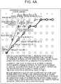
- FIG. 4 an example of state series data stored in a state series dictionary is shown.
- a finite state series that defines a series of the state change may be also called as the shape change since the shape changes) accompanying growth of a crop is applied, and a model configured of a finite state series that is obtained by modelling the shape of a crop of the initial state is prepared.
- a dictionary in which the objective attribute and the target parameter are related to a crop or the growth environment of a crop is prepared, and can be used for searching of the state series.
- the objective of a crop itself there are sprouting, growth, flower setting, flowering, fruition, firing, and so on
- the target parameter there are the height of a stem, the size of a leaf, the number of piece of the leaf, the color of a leaf, the gap between leaves, the number of piece of the flower, the size of the fruit, the shape of the fruit, and so on.
- a heater for properly keeping the growing temperature of a crop and a thermometer for observing the temperature
- a waterer for supplying water to a crop
- lighting for giving light to a crop
- a growth schedule of a crop as a cultivation plan and control information of the temperature, water supply, and lighting of the growth environment are given from the outside as the objective attribute and the objective parameter, they are also used for searching of the finite state series to execute growth prediction of a crop and are used as prediction values for the temperature sensor of a heater, the water supply sensor of a waterer, and the illuminance sensor of lighting.
- a deviation from an observation value When a deviation from an observation value is detected, by reversely searching the finite state series of a crop and growth environment so as to match the observation value, they may be outputted as excess and deficiency information of the temperature, water supply, lighting and the like and feedback information to controlling, may be outputted as abnormality detection of each sensor for the temperature, water supply, and lighting, and may be outputted as possibility information of the disease and insect damage.
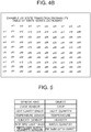
- Fig. 5 an example of model dictionary data is shown.
- the model dictionary the kind of sensor and the object determined based on sensor information outputted from the sensor are defined.
- Fig. 5 is a model dictionary that defines an object, and a crop is defined as an object defined by an output from a CMOS sensor for example.
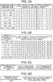
- Fig. 6 an example of a control parameter dictionary is shown.
- Fig. 6A is an example of a control parameter outputted to the lighting 401
- Fig. 6B is an example of a control parameter outputted to the heater 402
- Fig. 6C is an example of a control parameter outputted to the humidifying-dehumidifying device 403
- Fig. 6D is an example of a control parameter outputted to the water supply valve 404
- Fig. 6E is an example of a control parameter outputted to the fertilizer supply nozzle 405.
- the control parameter dictionary is given as data in which the values from the observation value to that after controlling are related to the difference of the expectation value and the observation value described below.
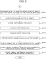
- Fig. 7 and Fig. 8 are flowcharts that show a flow of a process executing state prediction control with respect to growth of a crop using the state prediction control apparatus according to the present embodiment.
- the sensor information acquisition section 14a acquires sensor information at the clock time t1 of each sensor (will be hereinafter referred to as "the first sensor information") from each of the observation sensors 30 (S100), and outputs the same to the object identification section 14b.
- the object identification section 14b retrieves the model information dictionary 202, and identifies an object based on the first sensor information of each sensor (S101).
- model information dictionary 202 model information where the sensor kind and the object are related to each other, namely data where the object is defined to be "crop" when the sensor kind is "CMOS sensor” for example, is to be stored beforehand.
- the object identification section 14b acquires the first sensor information from the CMOS sensor, the object identification section 14b refers to the model information dictionary 202, and recognizes the object to be the crop if the first sensor information is acquired from the CMOS sensor.
- the object identification section 14b executes a process of adding new object information to the model dictionary and updating the model dictionary.
- the object identification section 14b sets a period where a state prediction control process of an object within an actual world is executed (will be referred to as a prediction searching window) (S102).
- a prediction searching window is set which is defined to be the time when the object is observed at a constant interval (refer to the reference sign 61 of Fig. 10 ).
- the constant interval described above is determined to be a predetermined interval namely one week for example as an example of the time interval in which growth of a crop can be compared.
- the object identification section 14b observes the object by the first sensor information within the prediction searching window, and determines the state of the object (S103). For example, the object identification section 14b determines the state (shape) of the crop at the first clock time t1 based on the first sensor information outputted from the CMOS sensor at the first clock time t1 that is included in the time defined to be the prediction searching window. Also, the object identification section 14b determines the moisture quantity at the first clock time t1 based on the first sensor information outputted from the water quantity sensor at the first clock time t1. In addition, the object identification section 14b determines a state at the first clock time t1 of the object determined based on each sensor included in the observation sensors 30.
- the sensor information acquisition section 14a acquires sensor information of each sensor includes in the observation sensors 30 at the second clock time t2 that is included within the prediction searching window and is after the first clock time t1 (will be hereinafter referred to as "the second sensor information") (S104).
- the object identification section 14b determines the state of the object based on the second sensor information (S105).
- the state prediction section 14c calculates the change quantity between the state at the first clock time t1 determined in S103 and the state at the second clock time t2 determined in S106 with respect to each object, and calculates the state change of the object from the first clock time t1 to the second clock time t2 of each object (S106).
- the state prediction section 14c retrieves the objective and target dictionary 201 with respect to the determined object, and selects the objective attribute and the target parameter of the object (S107).
- the state prediction section 14c retrieves the finite state series based on the object, the state of the object, and the objective attribute and the target parameter of the object, and selects at least one or more finite state series among the retrieved finite state series based on the arrival probability (S108). To be more specific, the state prediction section 14c calculates the square sum value of the difference between the observation value and the target value among the nodes of the finite state series, and retrieves a node where the square sum value is the smallest in the finite state series.
- the state prediction section 14c applies a selected series or plural series with high arrival probability at the time point of the retrieval to the object (S109).
- “To apply a series or plural series to the object” mentioned here means to determine the series having been narrowed as described above to be the state series of the object.
- the value of the node of the series applied is made the target value.
- the state prediction section 14c superposes the change vector of the object on the selected series (S110). When the object is observed, the state prediction section 14c calculates the change value between the difference value 1 and the difference value 2.
- the difference value 1 is difference value between senor information value of the object at the observation time point and the node of the state series applied before.
- the difference value 2 is difference value between sensor information value of the object at the next observation time point and the node of the state series applied the time point of the next observation. These are made the change vector of the object.
- the expectation value of the next observation time point is made a value obtained by superposing the change vector obtained above namely the change value of the difference value and the difference value on the node of the applied state series of the time point of the next observation.
- the state prediction section 14c updates searched state series frequency (S111). Out of the frequency of the entire state series of the object, the frequency of the applied state series arriving the objective and the target is made the arrival probability. Also, when the object has got a new state series, the state prediction section 14c executes updating of adding the new state series.
- the initial value of the frequency of the new state series is 1.
- the state prediction section 14c outputs state prediction (S112).
- the state prediction section 14c outputs, as a prediction value, a value obtained by superposing the change vector obtained above namely the change value of the difference value and the difference value on the node of the applied state series of the time point of the next observation obtained by superposition of the change vector of the object in the step S114.
- the prediction evaluation section 14d evaluates the outputted prediction value namely the result of the state prediction (S113).
- the state prediction is evaluated by calculating the arrival probability from the node to the objective and the target as an evaluation function.
- four kinds of data are outputted which are (1) the difference value of the sensor value (target value-observation value, target value-prediction value, expectation value-observation value), (2) the signed value corresponding to increase and decrease (the observation time point of the last time and the observation time point of this time) of the difference value of the sensor value, (3) the arrival probability from a node of the prediction value to a node of the objective and target value, the arrival probability from a node of the observation value to a node of the objective and target value, and the arrival probability from a node of the expectation value to a node of the objective and target value, (4) the signed value corresponding to increase and decrease (difference value between value of the observation time point of the last time and value of the observation time point of this time) of the arrival probability from a node of the prediction value to a node of the objective and target value, the signed value corresponding to increase and decrease (difference value between value of the observation time point of the last time and value of the observation time point of this time) of the arrival probability from
- the prediction evaluation section 14d retrieves the state series that comes close to the target (S114). In concrete terms, the prediction evaluation section 14d compares the arrival probability to the objective and the target from the node of the applied time point and the arrival probability to the objective and the target from the closest node of the prediction value to each other. When the arrival probability has reduced, the prediction evaluation section 14d retrieves a node whose arrival probability is higher compared to the closest node of the prediction value. When the arrival probability has increased, retrieval is not executed.
- the matching section 14f compares the observation value indicated by the second sensor information and the prediction information outputted by the state prediction section 14c to each other, and outputs the comparison result to the prediction evaluation section 14d.
- the prediction evaluation section 14d outputs at least one of evaluation information and expectation value (described “evaluation information/expectation value” below) based on this comparison result (S115).
- evaluation information and expectation value described “evaluation information/expectation value” below
- the prediction evaluation section 14d outputs a node whose arrival probability to the objective and the target is higher compared to the closest node of the prediction value retrieved in the step S118 as the expectation value.
- the prediction evaluation section 14d outputs the closest node of the prediction value as the expectation value.
- the prediction evaluation section 14d outputs the values described below as the evaluation information.
- the control section 14e outputs the control information (S116). Based on the evaluation value formed of the difference between the observation value and the expectation value outputted in the step S115, the control section 14e refers to the control parameter dictionary 204, and outputs the control information with respect to each object. For example, when the difference between the expectation value and the observation value of the light quantity is "800-1199 or more" and the lighting voltage at the time of observation obtained from the second sensor information is 3, as shown in Fig. 6A , the control information after control which indicates the value of the lighting voltage is "0" is outputted.
- a state ⁇ 1 of the first clock time t1 (this is an observation state since it is an actually observed state) has been obtained based on the first sensor information.
- a targeted state value is referred to as a target value
- a predicted state value is referred to as a prediction value
- an observed state value is referred to as an observation value
- an expected state value is referred to as an expectation value.
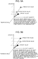
- Fig. 9A and Fig. 9B are drawings that show an example of changing a control parameter based on a prediction evaluation result.
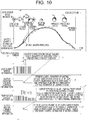
- Fig. 10 is a drawing that shows an example of growth prediction of a crop and a control parameter according to the growth prediction.
- the state prediction section 14c observed the state ⁇ at the second clock time t2.
- the state prediction section 14c generates a route connecting the state ⁇ 1 of the first clock time t1 (this is an observation state since it is an observed state) and the state ⁇ 3 of the second clock time t2 (this is an observation state since it is an observed state).
- the state prediction section 14c extends the route and predicts the state at the third clock time t3 to be ⁇ 6 (by probability searching of the state series dictionary).
- control section 14e executes probability searching of the state series dictionary, and outputs the expectation values of the light quantity, temperature, and growth for coming closest to the target value at time t3 are outputted as time t2 expectation values.
- the control section 14e searches an alternative route, and outputs the expectation values of the temperature and growth coming closest to the target value at the time t4 with a prediction that the light quantity does not change as a time t3 expectation value.
- the control section 14e executes probability searching of the state series dictionary, and outputs the expectation values of the light quantity, the temperature, and the growth for coming closest to the target value at the time t3 as time t2 expectation values.
- the expectation values where the light quantity and the temperature are lowered in order to prevent the spindly growth are outputted, and the expectation values of the light quantity and the temperature are outputted by a prior method separately from the expectation values.
- the state prediction section 14c updates the object and the arrival probability of the objective and target dictionary (S117).
- Fig. 4B an example of an update of the state series data of the state series dictionary is shown.
- each state has a state series frequency counter and a state counter, and the state prediction section 14c updates the state series frequency counter and the state counter whenever the state transition is observed.
- An example of an update of the state transition probability is shown below. Example: In observing the state transition of ⁇ n ⁇ n+1 State series frequency counter ⁇ n ⁇ n+1 count-up State counter ⁇ n+1 count-up
- the state series dictionary has the state transition probability data, obtains the state transition probability P( ⁇ n ⁇ n+1) by the equation (1) below based on the state series frequency, and updates the state transition probability.
- P ⁇ n ⁇ ⁇ n + 1 ⁇ ⁇ n ⁇ n + 1 count / ⁇ ⁇ n count
- the state transition probability of the objective and target dictionary can be updated using the observation result of the state transition, and accuracy of the state prediction can be further improved.
- the state of the observation object can be predicted, and the evaluation information for making the state prediction come close to the target value can be obtained. Therefore, based on this evaluation information, the factors affecting the state of the observation object can be changed so that a future state of the observation object comes close to the target value.
- control parameters can be changed so that the state prediction of the observation object comes close to the target value using the control section 14e.
- state series dictionary 203 and the objective and target dictionary 201 are updated by the state series dictionary editing section 203b and the objective and target dictionary editing section 201b based on the data of the observation object actually obtained, it can be expected to improve the state prediction accuracy.
- the state series dictionary editing section 203b puts an update flag to a focused state, adds a corresponding frequency flag when it becomes definite to arrive the objective and the target, and thereby updates the state transition probability.
- the objective and target dictionary editing section 201b may update the objective and target arrival probability.
- the state transition probability may be updated by putting an abnormal state transition flag when it is proved to be an abnormal case and adding a corresponding frequency flag.
- the state series dictionary editing section may register an update flag, a flag that shows to be in a new state, and a corresponding new frequency flag to update the state series dictionary memory.
Landscapes
- Engineering & Computer Science (AREA)
- Multimedia (AREA)
- Signal Processing (AREA)
- Computer Vision & Pattern Recognition (AREA)
- Life Sciences & Earth Sciences (AREA)
- General Physics & Mathematics (AREA)
- Physics & Mathematics (AREA)
- Botany (AREA)
- Artificial Intelligence (AREA)
- Forests & Forestry (AREA)
- Ecology (AREA)
- Biodiversity & Conservation Biology (AREA)
- Theoretical Computer Science (AREA)
- Health & Medical Sciences (AREA)
- Environmental Sciences (AREA)
- Evolutionary Computation (AREA)
- Medical Informatics (AREA)
- Software Systems (AREA)
- Automation & Control Theory (AREA)
- Feedback Control In General (AREA)
- Control Of Non-Electrical Variables (AREA)
- Testing Or Calibration Of Command Recording Devices (AREA)
- Testing And Monitoring For Control Systems (AREA)
Applications Claiming Priority (1)
| Application Number | Priority Date | Filing Date | Title |
|---|---|---|---|
| PCT/JP2017/019902 WO2018220673A1 (fr) | 2017-05-29 | 2017-05-29 | Dispositif de commande de prédiction d'état et procédé de commande de prédiction d'état |
Publications (2)
| Publication Number | Publication Date |
|---|---|
| EP3547068A1 true EP3547068A1 (fr) | 2019-10-02 |
| EP3547068A4 EP3547068A4 (fr) | 2020-07-22 |
Family
ID=64456405
Family Applications (1)
| Application Number | Title | Priority Date | Filing Date |
|---|---|---|---|
| EP17912304.7A Withdrawn EP3547068A4 (fr) | 2017-05-29 | 2017-05-29 | Dispositif de commande de prédiction d'état et procédé de commande de prédiction d'état |
Country Status (5)
| Country | Link |
|---|---|
| US (1) | US11006107B2 (fr) |
| EP (1) | EP3547068A4 (fr) |
| JP (1) | JP6556382B2 (fr) |
| CN (1) | CN110226147A (fr) |
| WO (1) | WO2018220673A1 (fr) |
Families Citing this family (5)
| Publication number | Priority date | Publication date | Assignee | Title |
|---|---|---|---|---|
| JOP20190145A1 (ar) * | 2017-06-14 | 2019-06-16 | Grow Solutions Tech Llc | أنظمة وطرق لتفريع حصاد قرن إنماء |
| JP2021005339A (ja) * | 2019-06-27 | 2021-01-14 | キヤノン株式会社 | 情報処理装置、その制御方法、及びプログラム |
| CN113869917A (zh) * | 2021-09-30 | 2021-12-31 | 广东技术师范大学 | 基于蔬菜的状态的追溯控制方法、装置 |
| JPWO2023189427A1 (fr) * | 2022-03-31 | 2023-10-05 | ||
| US12535788B2 (en) * | 2022-06-17 | 2026-01-27 | AIMDYN, Inc. | Lifted predictive modeling and control for digital twin system optimization |
Family Cites Families (12)
| Publication number | Priority date | Publication date | Assignee | Title |
|---|---|---|---|---|
| JPS6391018A (ja) * | 1986-10-06 | 1988-04-21 | 横河電機株式会社 | 温室のプログラム制御方法 |
| JP2996952B1 (ja) * | 1998-07-17 | 2000-01-11 | 株式会社エイ・ティ・アール人間情報通信研究所 | 学習制御方法および学習制御装置 |
| JP4382597B2 (ja) | 2003-07-10 | 2009-12-16 | 株式会社国際電気通信基礎技術研究所 | 推定装置、推定方法および推定プログラム |
| JP4921847B2 (ja) | 2006-05-02 | 2012-04-25 | 株式会社豊田中央研究所 | 対象物の三次元位置推定装置 |
| JP5838940B2 (ja) | 2012-09-20 | 2016-01-06 | 株式会社デンソー | 画像処理装置及び車両制御システム |
| JP6261492B2 (ja) * | 2014-11-28 | 2018-01-17 | 三菱電機株式会社 | 情報処理装置及び情報処理方法及びプログラム |
| US9878710B2 (en) * | 2015-05-04 | 2018-01-30 | Honda Research Institute Europe Gmbh | Method for improving performance of a method for computationally predicting a future state of a target object, driver assistance system, vehicle including such driver assistance system and respective program storage medium and program |
| US10194059B2 (en) * | 2015-09-25 | 2019-01-29 | Hitach Information & Telecommunication Engineering, Ltd. | Image processing apparatus and image processing method |
| WO2017110278A1 (fr) * | 2015-12-25 | 2017-06-29 | 富士フイルム株式会社 | Dispositif de traitement d'informations et procédé de traitement d'informations |
| CN106157163A (zh) * | 2016-07-27 | 2016-11-23 | 河南工业大学 | 一种粮食产量短期预测方法及装置 |
| US10740658B2 (en) * | 2016-09-08 | 2020-08-11 | Mentor Graphics Corporation | Object recognition and classification using multiple sensor modalities |
| JP6431204B2 (ja) | 2016-09-13 | 2018-11-28 | 株式会社日立情報通信エンジニアリング | 状態予測装置及び状態予測方法 |
-
2017
- 2017-05-29 JP JP2018558435A patent/JP6556382B2/ja not_active Expired - Fee Related
- 2017-05-29 US US16/477,447 patent/US11006107B2/en not_active Expired - Fee Related
- 2017-05-29 EP EP17912304.7A patent/EP3547068A4/fr not_active Withdrawn
- 2017-05-29 WO PCT/JP2017/019902 patent/WO2018220673A1/fr not_active Ceased
- 2017-05-29 CN CN201780083604.9A patent/CN110226147A/zh active Pending
Also Published As
| Publication number | Publication date |
|---|---|
| EP3547068A4 (fr) | 2020-07-22 |
| US11006107B2 (en) | 2021-05-11 |
| CN110226147A (zh) | 2019-09-10 |
| JP6556382B2 (ja) | 2019-08-07 |
| WO2018220673A1 (fr) | 2018-12-06 |
| JPWO2018220673A1 (ja) | 2019-06-27 |
| US20190387223A1 (en) | 2019-12-19 |
Similar Documents
| Publication | Publication Date | Title |
|---|---|---|
| EP3547068A1 (fr) | Dispositif de commande de prédiction d'état et procédé de commande de prédiction d'état | |
| JP6261492B2 (ja) | 情報処理装置及び情報処理方法及びプログラム | |
| JP6532722B2 (ja) | 予測装置および予測方法 | |
| CN113196320A (zh) | 果菜类植物和果树栽培管理装置、学习装置、果菜类植物和果树栽培管理方法、学习模型生成方法、果菜类植物和果树栽培管理程序以及学习模型生成程序 | |
| US20210051849A1 (en) | Enhancement of combine harvester yield data through augmentation with spatial grain cart data | |
| JP2018029568A (ja) | 萎れ具合予測システム及び萎れ具合予測方法 | |
| JP6589978B2 (ja) | 植物健全性診断装置、該方法および該プログラム | |
| JP2019083746A (ja) | 作物生産管理装置 | |
| KR20140077513A (ko) | 영상을 통한 온실 작물 정보 관리 시스템 및 그 방법 | |
| JP2017042133A (ja) | 植物生長速度算出システム、及び植物生長速度算出方法 | |
| US20240169721A1 (en) | Computer-implemented method for providing corrected plant-related index data | |
| CN118395386B (zh) | 面向智慧植物工厂的植物生长监测方法 | |
| KR102355211B1 (ko) | 농작물 재배 모니터링 시스템 | |
| JP2019219704A (ja) | 農業経営支援システム | |
| JP2019219704A5 (fr) | ||
| KR20160076317A (ko) | 병해충 발생 예측 장치 및 방법 | |
| JP2024176406A (ja) | 生育状態推定装置、植物管理システム、生育状態推定方法、及びプログラム | |
| US20240237569A1 (en) | Growth information providing apparatus, growth information providing method, and storage medium | |
| US20220189025A1 (en) | Crop yield prediction program and cultivation environment assessment program | |
| JP2019054771A (ja) | 予測装置、予測方法および予測プログラム | |
| KR20180029381A (ko) | 시설원예 환경 제어 장치 및 방법 | |
| JP6943725B2 (ja) | 生長状態予測装置 | |
| JP2018201417A (ja) | 収量予測システム | |
| US20230385703A1 (en) | High-resolution environmental sensor imputation using machine learning | |
| KR20200057830A (ko) | 시설원예 운영 시스템, 재배환경 분석 시스템 및 그 방법들 |
Legal Events
| Date | Code | Title | Description |
|---|---|---|---|
| STAA | Information on the status of an ep patent application or granted ep patent |
Free format text: STATUS: THE INTERNATIONAL PUBLICATION HAS BEEN MADE |
|
| PUAI | Public reference made under article 153(3) epc to a published international application that has entered the european phase |
Free format text: ORIGINAL CODE: 0009012 |
|
| STAA | Information on the status of an ep patent application or granted ep patent |
Free format text: STATUS: REQUEST FOR EXAMINATION WAS MADE |
|
| 17P | Request for examination filed |
Effective date: 20190627 |
|
| AK | Designated contracting states |
Kind code of ref document: A1 Designated state(s): AL AT BE BG CH CY CZ DE DK EE ES FI FR GB GR HR HU IE IS IT LI LT LU LV MC MK MT NL NO PL PT RO RS SE SI SK SM TR |
|
| AX | Request for extension of the european patent |
Extension state: BA ME |
|
| RIN1 | Information on inventor provided before grant (corrected) |
Inventor name: UEJIMA, TOSHIAKI |
|
| A4 | Supplementary search report drawn up and despatched |
Effective date: 20200622 |
|
| RIC1 | Information provided on ipc code assigned before grant |
Ipc: G05D 27/00 20060101AFI20200616BHEP Ipc: A01G 7/00 20060101ALI20200616BHEP Ipc: G06T 7/00 20170101ALI20200616BHEP Ipc: G05B 13/04 20060101ALI20200616BHEP |
|
| DAV | Request for validation of the european patent (deleted) | ||
| DAX | Request for extension of the european patent (deleted) | ||
| STAA | Information on the status of an ep patent application or granted ep patent |
Free format text: STATUS: EXAMINATION IS IN PROGRESS |
|
| 17Q | First examination report despatched |
Effective date: 20211206 |
|
| STAA | Information on the status of an ep patent application or granted ep patent |
Free format text: STATUS: THE APPLICATION HAS BEEN WITHDRAWN |
|
| 18W | Application withdrawn |
Effective date: 20220223 |