EP3547393A1 - Support et ensemble de batterie - Google Patents
Support et ensemble de batterie Download PDFInfo
- Publication number
- EP3547393A1 EP3547393A1 EP18185647.7A EP18185647A EP3547393A1 EP 3547393 A1 EP3547393 A1 EP 3547393A1 EP 18185647 A EP18185647 A EP 18185647A EP 3547393 A1 EP3547393 A1 EP 3547393A1
- Authority
- EP
- European Patent Office
- Prior art keywords
- positioning
- side wall
- carriers
- carrier
- battery assembly
- Prior art date
- Legal status (The legal status is an assumption and is not a legal conclusion. Google has not performed a legal analysis and makes no representation as to the accuracy of the status listed.)
- Granted
Links
Images




Classifications
-
- H—ELECTRICITY
- H01—ELECTRIC ELEMENTS
- H01M—PROCESSES OR MEANS, e.g. BATTERIES, FOR THE DIRECT CONVERSION OF CHEMICAL ENERGY INTO ELECTRICAL ENERGY
- H01M50/00—Constructional details or processes of manufacture of the non-active parts of electrochemical cells other than fuel cells, e.g. hybrid cells
- H01M50/20—Mountings; Secondary casings or frames; Racks, modules or packs; Suspension devices; Shock absorbers; Transport or carrying devices; Holders
- H01M50/204—Racks, modules or packs for multiple batteries or multiple cells
- H01M50/207—Racks, modules or packs for multiple batteries or multiple cells characterised by their shape
- H01M50/213—Racks, modules or packs for multiple batteries or multiple cells characterised by their shape adapted for cells having curved cross-section, e.g. round or elliptic
-
- H—ELECTRICITY
- H01—ELECTRIC ELEMENTS
- H01M—PROCESSES OR MEANS, e.g. BATTERIES, FOR THE DIRECT CONVERSION OF CHEMICAL ENERGY INTO ELECTRICAL ENERGY
- H01M50/00—Constructional details or processes of manufacture of the non-active parts of electrochemical cells other than fuel cells, e.g. hybrid cells
- H01M50/20—Mountings; Secondary casings or frames; Racks, modules or packs; Suspension devices; Shock absorbers; Transport or carrying devices; Holders
- H01M50/256—Carrying devices, e.g. belts
-
- H—ELECTRICITY
- H01—ELECTRIC ELEMENTS
- H01M—PROCESSES OR MEANS, e.g. BATTERIES, FOR THE DIRECT CONVERSION OF CHEMICAL ENERGY INTO ELECTRICAL ENERGY
- H01M2220/00—Batteries for particular applications
- H01M2220/20—Batteries in motive systems, e.g. vehicle, ship, plane
-
- Y—GENERAL TAGGING OF NEW TECHNOLOGICAL DEVELOPMENTS; GENERAL TAGGING OF CROSS-SECTIONAL TECHNOLOGIES SPANNING OVER SEVERAL SECTIONS OF THE IPC; TECHNICAL SUBJECTS COVERED BY FORMER USPC CROSS-REFERENCE ART COLLECTIONS [XRACs] AND DIGESTS
- Y02—TECHNOLOGIES OR APPLICATIONS FOR MITIGATION OR ADAPTATION AGAINST CLIMATE CHANGE
- Y02E—REDUCTION OF GREENHOUSE GAS [GHG] EMISSIONS, RELATED TO ENERGY GENERATION, TRANSMISSION OR DISTRIBUTION
- Y02E60/00—Enabling technologies; Technologies with a potential or indirect contribution to GHG emissions mitigation
- Y02E60/10—Energy storage using batteries
Definitions
- the invention relates to a carrier and a battery assembly, and more particularly, to a carrier and a battery assembly using the carrier.
- Electric-driven vehicles e.g., electric cars, electric vehicles and electric bicycles
- Battery modules that provide power for electric vehicles, electric vehicles, and electric bicycles have become the most important link for related manufacturers.
- a common battery module includes multiple battery assemblies.
- Each of the battery assemblies holds and secures one to three batteries by two carriers disposed in pairs. These batteries are connected in series or in parallel through electrode pieces.
- the carriers of the battery assemblies are often secured by screws and the corresponding accessories, which are inconvenient for assembly.
- the invention is directed to a carrier and a battery assembly using the carrier, which are very convenient for assembly.
- the carrier of the invention includes a body, at least one first positioning structure and at least one second positioning structure.
- the body has a first side wall, a second side wall and a plurality of inserting grooves.
- the second side wall is opposite to the first side wall, and the inserting grooves are arranged side by side and located between the first side wall and the second side wall.
- the first positioning structure is disposed at the first side wall.
- the first positioning structure includes a first positioning protrusion and a second positioning protrusion connected to each other.
- the second positioning structure is disposed at the second side wall.
- the second positioning structure includes a first positioning recess and a second positioning recess communicating with each other.
- a geometric profile of the first positioning protrusion along a direction perpendicular to the first side wall is conformal with a geometric profile of the first positioning recess along a direction perpendicular to the second side wall.
- a geometric profile of the second positioning protrusion along the direction perpendicular to the first side wall is conformal with a geometric profile of the second positioning recess along the direction perpendicular to the second side wall.
- the battery assembly of the invention includes a plurality of carriers and a plurality of batteries.
- the carriers are arranged side by side.
- Each of the carriers includes a body, at least one first positioning structure and at least one second positioning structure.
- the body has a first side wall, a second side wall and a plurality of inserting grooves.
- the second side wall is opposite to the first side wall, and the inserting grooves are arranged side by side and located between the first side wall and the second side wall.
- the first positioning structure is disposed at the first side wall.
- the first positioning structure includes a first positioning protrusion and a second positioning protrusion connected to each other.
- the second positioning structure is disposed at the second side wall.
- the second positioning structure includes a first positioning recess and a second positioning recess communicating with each other.
- a geometric profile of the first positioning protrusion along a direction perpendicular to the first side wall is conformal with a geometric profile of the first positioning recess along a direction perpendicular to the second side wall.
- a geometric profile of the second positioning protrusion along the direction perpendicular to the first side wall is conformal with a geometric profile of the second positioning recess along the direction perpendicular to the second side wall.
- the second positioning protrusion of one of the carriers and the second positioning protrusion of another one of the carriers face each other.
- the inserting grooves of one of the carriers are respectively aligned with the inserting grooves of another one of the carriers.
- Two opposite end portions of each of the batteries are respectively inserted to one of the inserting grooves of one of the carriers and another one of the inserting grooves of another one of the carriers.
- the battery assembly of the invention includes a plurality of carriers, and each of the carriers has the same design for positioning structure and can provide excellent versatility and expandability.
- the user may have these two carriers assembled in an assembling direction.
- the two carriers may be detached in an inverse direction of the assembling direction, and thus are very convenient for assembly and disassembly.
- FIG. 1 is an explosion schematic view of a battery assembly in an embodiment of the invention.
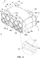
- FIG. 2 is a schematic structural view of the battery assembly of FIG. 1 .
- FIG. 3 is a front view of the battery assembly of FIG. 2 .
- a battery assembly 10 is applicable to electric cars, electric cars or electric bicycles for providing said vehicles power to move. More specifically, the battery assembly 10 may be formed by a first battery pack 11 engaged with a second battery pack 12.
- the first battery pack 11 includes a first carrier 100a, a second carrier 100b and a plurality of first barriers 20a
- the second battery pack 12 includes a third carrier 100c, a fourth carrier 100d and a plurality of second batteries 20b.
- the first carrier 100a and the second carrier 100b are arranged side by side, and configured to hold and secure the first batteries 20a.
- the third carrier 100c and the fourth carrier 100d are arranged side by side, and configured to hold and secure the second batteries 20b.
- the number of the battery packs is not particularly limited in the invention. Instead, the number of the battery packs may be increased or decreased depending on design of power storage capacity for the battery assembly.
- the first carrier 100a to the fourth carrier 100d have the same structural design and can provide excellent versatility and expandability.
- a structure design of the first carrier 100a and an assembling method of the battery assembly 10 will be described below. Because of the same structural design, description regarding the second carrier 100b to the fourth carrier 100d may correspondingly refer to the structural design of the first carrier 100a, which is not repeatedly described.
- FIG. 4 is a schematic structural view of one of the carriers of FIG. 1 from another viewing angle.
- FIG. 5 is a front view of the carrier of FIG. 4 .
- FIG. 6 is a schematic structural view of one of the carriers of FIG. 1 from yet another viewing angle.
- FIG. 7 is a front view of the carrier of FIG. 6 .
- the first carrier 100a includes a body 110, at least one first positioning structure 120 and at least one second positioning structure 130.
- the number of the at least one first positioning structure 120 may be two, and the first positioning structures 120 are symmetrically disposed at one side of the body 110.
- the number of the at least one second positioning structure 130 may be two, and the second positioning structure 130 are symmetrically disposed at another side of the body 110.
- the number of the at least one first positioning structure and the number of the at least one second positioning structure are not particularly limited in the invention. In other words, the number of the at least one first positioning structure and the number of the at least one second positioning structure may be increased or decreased depending on design requirements.
- the body 110 has a first side wall 111, a second side wall 112 opposite to the first side wall 111 and a plurality of inserting grooves 113.
- the second side wall 112 is substantially parallel to the first side wall 111, and the inserting grooves 113 are arranged side by side and located between the first side wall 111 and the second side wall 112.
- the first positioning structures 120 are disposed side by side on the first side wall 111, and the second positioning structures 130 are disposed side by side on the second side wall 112.
- the first positioning structures 120 are respectively aligned with the second positioning structures 130 along a direction perpendicular to the first side wall 111 or the second side wall 112.
- first positioning structures may be staggered with respect to the second positioning structures along the direction perpendicular to the first sidewall or the second side wall, which are not particularly limited in the invention.
- each of the first positioning structures 120 may be a dovetail tenon, and may include a first positioning protrusion 121 and a second positioning protrusion 122 connected to each other.
- Each of the first positioning protrusions 121 has a first height HI
- each of the second positioning protrusions 122 has a second height H2 less than the first height HI.
- the first height HI is calculated from the bottom of each of the first positioning protrusions 121 connected to the body 110 to the top of the respective first positioning protrusion 121.
- the second height H2 is calculated from the bottom of each of the second positioning protrusions 122 connected to the body 110 to the top of the respective second positioning protrusion 122.
- a geometric profile of each of the first positioning protrusions 121 along the direction perpendicular to the first side wall 111 is different from a geometric profile of the corresponding second positioning protrusion 122 along the direction perpendicular to the first side wall 111.
- Each of the second positioning protrusions 122 may be a square pillar, whereas each of the first positioning protrusions 121 may include a square pillar and a mushroom-like protrusion connected to the square pillar.
- each of the second positioning structures 130 may be a dovetail groove, and may include a first positioning recess 131 and a second positioning recess 132 communicating with each other.
- Each of the first positioning recesses 131 has a first depth D1
- each of the second positioning recesses 132 has a second depth D2 less than the first depth D1.
- the first depth D1 is calculated from a lateral surface of the body 110 to the bottom of each of the first positioning recesses 131.
- the second depth D2 is calculated from the lateral surface of the body 110 to the bottom of each of the second positioning recesses 132.
- a geometric profile of each of the first positioning recesses 131 along the direction perpendicular to the second side wall 112 is different from a geometric profile of the corresponding second positioning recess 132 along the direction perpendicular to the second side wall 112.
- Each of the second positioning recesses 132 may be a square slot, whereas each of the first positioning recesses 131 may include a square slot and a mushroom-like recess connected to the square slot.
- the second positioning protrusions 122 of the first carrier 100a respectively face the second positioning protrusions 122 of the second carrier 100b, and the inserting grooves 113 of the first carrier 100a are respectively aligned with the inserting grooves 113 of the second carrier 100b.
- Two opposite end portions of each of the first batteries 20a are respectively inserted to one group of the inserting grooves 113 aligned with each other.
- the two opposite end portions of each of the first batteries 20a are respectively inserted to one of the inserting grooves 113 of the first carrier 100a and another one of the inserting grooves 113 of the second carrier 100b. Since the third carrier 100c, the fourth 100d and the second batteries 20b are disposed in the same manner as the first carrier 100a, the second carrier 100b and the first batteries 20a, and related description regarding the same is not repeated hereinafter.
- the geometric profile of each of the first positioning protrusions 121 along the direction perpendicular to the first side wall 111 is conformal with the geometric profile of the corresponding first positioning recess 131 along the direction perpendicular to the second side wall 112, and the geometric profile of each of the second positioning protrusions 122 along the direction perpendicular to the first side wall 111 is conformal with the geometric profile of the corresponding second positioning recess 132 along the direction perpendicular to the second side wall 112.
- the first depth D1 of each of the first positioning recesses 131 is greater than the second depth D2 of the corresponding second positioning recess 132.
- Complementary relation between the geometrical profiles of each of the first positioning protrusions 120 and the corresponding second positioning protrusion 130 and design of the step between each of the first positioning recesses 131 and the corresponding second positioning recess 132 can help to improve reliability and convenience when stacking and engaging the first carrier 100a with the third carrier 100c and reliability and convenience when stacking and engaging the second carrier 100b with the fourth carrier 100d.
- the two overlap in the direction perpendicular to the first side wall 111 or the second side wall 112 and the first side wall 111 of the first carrier 100a faces the second side wall 112 of the third carrier 100c.
- Each of the first positioning protrusions 121 of the first carrier 100a is inserted to the corresponding first positioning recess 131 in the third carrier 100c, and each of the second positioning protrusions 122 of the first carrier 100a is inserted to the corresponding second positioning recess 132 in the third carrier 100c.
- the third carrier 100c cannot be moved relative to the first carrier 100a along a direction D parallel to the first side wall 111 or the second side wall 112.
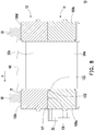
- FIG. 8 is a cross-sectional view of FIG. 3 along line I-I.
- each of the first positioning recesses 131 of the third carrier 100c needs to be aligned with the corresponding second positioning protrusion 122 in the first carrier 100a first.
- the third 100c is moved relative to the first carrier 100a along the direction D parallel to the first side wall 111 or the second side wall 112. Meanwhile, each of the first positioning recesses 131 of the third carrier 100c is moved and passed through the corresponding second positioning protrusions 122 in the first carrier 100a.
- the movement of the third carrier 100c relative to the first carrier 100a is stopped after each of the first positioning protrusions 121 of the first carrier 100a is completely contained in the corresponding first positioning recess 131 in the third carrier 100c.
- each of the second positioning protrusions 122 of the first carrier 100a is also completely contained in the corresponding second positioning recess 132 in the third carrier 100c.
- the third carrier 100c can no longer be moved relative to the first carrier 100a along the direction D parallel to the first side wall 111 or the second side wall 112. On the contrary, the third carrier 100c may be moved relative to the first carrier 100a in an inverse direction of the direction D to be detached.
- FIG. 9 is a cross-sectional view of FIG. 3 along line J-J.
- the first side wall 111 of the first carrier 100a further includes at least two third positioning recesses 111a and at least two stoppers 111b. More specifically, one side of each of the first positioning structures 120 is disposed with one group of the third positioning recess 111a and the stopper 111b, and another side of each of the first positioning structures 120 is disposed with another group of the third positioning recess 111a and the stopper 111b. On the other hand, each of the stoppers 111b is disposed at one side of the corresponding third positioning recess 111a opposite to the second positioning protrusion 122.
- the second side wall 112 of the first carrier 100a further includes at least two third positioning protrusions 112a. More specifically, one side of each of the second positioning structures 130 is disposed with one of the third positioning protrusions 112a, and another side of each of the second positioning structures 130 is disposed with another one of the third positioning protrusions 112a.
- an extended length E1 of each of the third positioning protrusions 112a along the direction parallel to the first side wall 111 or the second side wall 112 is substantially equal to an extended length E2 of the corresponding third positioning recess 111a along the direction parallel to the first side wall 111 or the second side wall 112.
- each of the third positioning protrusions 112a of the third carrier 100 is inserted to the corresponding third positioning recess 111a in the first carrier 100a, and each of the third positioning protrusions 112a of the third carrier 100c abuts against the corresponding stopper 111b in the first carrier 100a.
- each of the third positioning protrusions 112a of the third carrier 100c needs to be aligned with the corresponding third positioning recess 111a in the first carrier 100a first.
- the third 100c is moved relative to the first carrier 100a along the direction D parallel to the first side wall 111 or the second side wall 112.
- each of the third positioning protrusions 112a of the third carrier 100c is moved in the corresponding third positioning recess 111a of the first carrier 100a. Also, after each of the third positioning protrusions 112a of the third carrier 100c is completely contained in the corresponding third positioning recess 111a in the first carrier 100a and abuts against the corresponding stopper 111b, the third carrier 100c can no longer be moved relative to the first carrier 100a along the direction D. On the contrary, the third carrier 100c may be moved relative to the first carrier 100a in an inverse direction of the direction D to be detached.
- the first side wall 111 of the first carrier 100a further includes at least one first groove 111c and at least two extended portions 111d.
- the number of the at least one first groove 111c may be two, and the interior of each of the first grooves 111c may be disposed with two extended portions 111d. More specifically, the two extended portions 111d disposed in pair are respectively extended inwardly from the two opposite side edges of the corresponding first groove 111c, and a gap is kept between the two extended portions 111d disposed in pair for use in the subsequent process of routing.
- the second side wall 112 of the first carrier 100a is disposed with two second grooves 112b, and each of the first grooves 111c overlaps with the corresponding second groove 112b along the direction perpendicular to the first side wall 111 or the second side wall 112.
- each of the first grooves 111c of the first carrier 100a is aligned with the corresponding second groove 112b in the third carrier 100c, and each of the first grooves 111c and the corresponding second groove 112b are communicating with each other.
- the body of the first carrier 100a further includes a plurality of oblique bumps 140, and each of the inserting grooves 113 has a first opening 113a and a second opening 113b opposite to each other.
- the oblique bumps 140 are respectively disposed in the inserting grooves 113 adjacent to the first openings 113a and obliquely extended from the first openings 113a down towards the second openings 113b.
- the end portion of each of the first batteries 20a inserted to the corresponding inserting groove 113 abuts against the corresponding oblique bump 140 to prevent each of the first batteries 20a from sliding out from the corresponding first opening 113a.
- the body 110 of the first carrier 100a further includes a third side wall 114 connected to the first side wall 111 and the second side wall 112.
- the third side wall 113 is perpendicularly connected to the first side wall 111 and the second side wall 112, and the inserting grooves 113 penetrate the third side wall 114 to respectively form the first openings 113a at the third side wall 114.
- the third side wall 114 of the body 110 is disposed with a plurality of limiting portions 114a respectively extended inwardly from side edges of the inserting grooves 113 (or extended into the first openings 113a).
- the end portion of each of the first batteries 20a inserted to the corresponding inserting groove 113 abuts against the corresponding limiting portion 114a to prevent each of the first batteries 20a from sliding out from the corresponding first opening 113a.
- structural designs of the second carrier 100b to the fourth carrier 100d may refer the structural design of the first carrier 100a as described above.
- how the second carrier 100b and the fourth carrier 100d are stacked and engaged may also refer to how the first carrier 100a and the third carrier 100c are stacked and engaged as described above.
- the battery assembly 10 of this embodiment is composed of the first battery pack 11 and the second battery pack 12 stacked and engaged together, and each of the battery packs includes at least five batteries. That is to say, each of the carriers has at least five inserting grooves. Such design helps to improve power storage capacity of the battery assembly 10.
- the battery assembly 10 further includes a plurality of supporting members 30, detachably disposed on the second battery pack 12.
- Each of the supporting members 30 has a supporting portion 31 and an engaging portion 32 opposite to the supporting portion 31.
- a part of the supporting members 30 is disposed at the first side wall 111 of the third carrier 100c
- another part of the supporting members 30 is disposed at the first side wall 111 of the fourth carrier 100d.
- the engaging portion 32 of each of the supporting members 30 disposed at the first side wall 111 of the third carrier 100c is engaged with the corresponding first positioning protrusion 121 and abuts against the corresponding two stoppers 111b.
- each of the supporting members 30 disposed at the first side wall 111 of the third carrier 100c will not be moved relative to the third carrier 100c along the direction D parallel to the first side wall 111 or the second side wall 112.
- the engaging portion 32 of each of the supporting members 30 disposed at the first side wall 111 of the fourth carrier 100d is engaged with the corresponding first positioning protrusion 121 and abuts against the corresponding two stoppers 111b. Therefore, each of the supporting members 30 disposed at the first side wall 111 of the fourth carrier 100d will not be moved relative to the first carrier 100a along the inverse direction of the direction D.
- the engaging portion 32 of each of the supporting members 30 has an engaging recess 32a and two engaging protrusions 32b located at two opposite sides of the engaging recess 32a, the engaging recess 32a of each of the supporting members 30 is sleeved on the corresponding first positioning protrusion 121, and the two engaging protrusions 32b of each of the supporting members 30 are respectively inserted to the corresponding two third positioning recesses 111a and abut against the corresponding two stoppers 111b.
- the supporting portions 31 of the supporting members 30 face one another.
- carrying surfaces of the supporting portions 31 used to carry a protection circuit module 40 all face the same side (e.g., at the same horizontal level), and are configured to commonly carry the protection circuit module 40 and prevent the protection circuit module 40 from tilting.
- Each of the supporting members 30 further includes a limiting protrusion 33 connected to the carrying surface of the supporting portion 31, and the protection circuit module 40 has a plurality of limiting recesses 41.
- the limiting protrusions 33 of the supporting member 31 face one another, and the limiting recesses 41 are respectively sleeved on the limiting protrusions 33 so as to ensure that the protection circuit module 40 are steadily held and secured between the supporting members 30.
- a plurality of locking holes 42 can be opened on the protection circuit module 40, and the carrying surface of the supporting portion 31 of each of the supporting members 30 may be disposed with a plurality of locking holes 34.
- the locking holes 42 may be respectively aligned with the locking holes 34, so a plurality of screws (not illustrated) may then be locked onto the locking holes 42 and the locking holes 32 aligned with each other to prevent the protection circuit module 40 from dropping off.
- the first batteries 20a and the second batteries 20b may be connected in series or in parallel through electrode pieces (not illustrated), and may be electrically connected to the protection circuit module 40.
- the two engaging protrusions 32b of each of the supporting members 30 are partially protruded, and may be configured to be inserted from the third side wall 114 of the corresponding carrier into the first groove 111c and the second groove 112b communicating with each other, as shown in FIG.1 and FIG. 2 .
- the battery assembly 10 may abut against inner walls of the shell cover (not illustrated) of shell cover (not illustrated) through the supporting members 30 to prevent the battery assembly 10 from sliding freely in the shell cover (not illustrated).
- the battery assembly of the invention includes a plurality of carriers, and each of the carriers has the same design for positioning structure and can provide excellent versatility and expandability.
- the user may have these two carriers assembled in an assembling direction.
- the two carriers may be detached in an inverse direction of the assembling direction, and thus are very convenient for assembly and disassembly.
- the user may have one of the two carriers moved relative to another carrier along the assembling direction. Further, once the positioning structures of any two carriers are engaged and moved in position, one of the corresponding two carriers can no longer be moved relative to another carrier along the assembling direction. Based on the positioning mechanism described above, reliability of the battery assembly of the invention may be improved to prevent each component from separating easily.
Landscapes
- Chemical & Material Sciences (AREA)
- Chemical Kinetics & Catalysis (AREA)
- Electrochemistry (AREA)
- General Chemical & Material Sciences (AREA)
- Battery Mounting, Suspending (AREA)
Applications Claiming Priority (1)
| Application Number | Priority Date | Filing Date | Title |
|---|---|---|---|
| TW107111129A TWI669845B (zh) | 2018-03-30 | 2018-03-30 | 載架與電池總成 |
Publications (2)
| Publication Number | Publication Date |
|---|---|
| EP3547393A1 true EP3547393A1 (fr) | 2019-10-02 |
| EP3547393B1 EP3547393B1 (fr) | 2020-09-09 |
Family
ID=63209164
Family Applications (1)
| Application Number | Title | Priority Date | Filing Date |
|---|---|---|---|
| EP18185647.7A Not-in-force EP3547393B1 (fr) | 2018-03-30 | 2018-07-26 | Support et ensemble de batterie |
Country Status (4)
| Country | Link |
|---|---|
| US (1) | US11043712B2 (fr) |
| EP (1) | EP3547393B1 (fr) |
| CN (1) | CN110323378B (fr) |
| TW (1) | TWI669845B (fr) |
Families Citing this family (2)
| Publication number | Priority date | Publication date | Assignee | Title |
|---|---|---|---|---|
| CN111211271B (zh) * | 2020-03-19 | 2022-04-19 | 英业达科技有限公司 | 电池载体 |
| USD1012853S1 (en) * | 2020-03-24 | 2024-01-30 | Acer Incorporated | Battery holder |
Citations (3)
| Publication number | Priority date | Publication date | Assignee | Title |
|---|---|---|---|---|
| EP0875948A1 (fr) * | 1997-04-28 | 1998-11-04 | Alcatel | Dispositif d'assemblage en batterie de générateurs électrochimiques |
| EP1069631A1 (fr) * | 1999-07-15 | 2001-01-17 | Black & Decker Inc. | Module de batterie et son procédé de fabrication |
| EP2690684A2 (fr) * | 2011-03-21 | 2014-01-29 | Lg Chem, Ltd. | Support de cellule de batterie possédant une fiabilité améliorée de connexion, et module batterie comprenant ledit support |
Family Cites Families (6)
| Publication number | Priority date | Publication date | Assignee | Title |
|---|---|---|---|---|
| JP2008258156A (ja) * | 2007-03-15 | 2008-10-23 | Matsushita Electric Ind Co Ltd | 電池モジュール |
| TWM337852U (en) * | 2008-03-11 | 2008-08-01 | Welldone Company | Battery assembly rack |
| CN102034948A (zh) * | 2010-12-07 | 2011-04-27 | 东莞市钜大电子有限公司 | 电池单体支架及其组合式电池支架 |
| ES2535152B1 (es) * | 2013-10-03 | 2015-11-24 | Caf Power & Automation, S.L.U. | Cesta de acumulación de energía |
| US10497909B2 (en) * | 2014-09-05 | 2019-12-03 | Ford Global Technologies, Llc | Battery assembly with snap-in arrays |
| CN107230756A (zh) * | 2017-07-03 | 2017-10-03 | 系统电子科技(镇江)有限公司 | 一种高强度的电芯支架 |
-
2018
- 2018-03-30 TW TW107111129A patent/TWI669845B/zh active
- 2018-05-17 CN CN201810473221.9A patent/CN110323378B/zh not_active Expired - Fee Related
- 2018-07-26 EP EP18185647.7A patent/EP3547393B1/fr not_active Not-in-force
- 2018-07-26 US US16/045,780 patent/US11043712B2/en active Active
Patent Citations (3)
| Publication number | Priority date | Publication date | Assignee | Title |
|---|---|---|---|---|
| EP0875948A1 (fr) * | 1997-04-28 | 1998-11-04 | Alcatel | Dispositif d'assemblage en batterie de générateurs électrochimiques |
| EP1069631A1 (fr) * | 1999-07-15 | 2001-01-17 | Black & Decker Inc. | Module de batterie et son procédé de fabrication |
| EP2690684A2 (fr) * | 2011-03-21 | 2014-01-29 | Lg Chem, Ltd. | Support de cellule de batterie possédant une fiabilité améliorée de connexion, et module batterie comprenant ledit support |
Also Published As
| Publication number | Publication date |
|---|---|
| EP3547393B1 (fr) | 2020-09-09 |
| TW201943119A (zh) | 2019-11-01 |
| CN110323378B (zh) | 2022-01-11 |
| US11043712B2 (en) | 2021-06-22 |
| TWI669845B (zh) | 2019-08-21 |
| CN110323378A (zh) | 2019-10-11 |
| US20190305267A1 (en) | 2019-10-03 |
Similar Documents
| Publication | Publication Date | Title |
|---|---|---|
| KR102162968B1 (ko) | 확장형 배터리 모듈 구조를 갖는 배터리 팩 | |
| EP3188281B1 (fr) | Plateau de batterie | |
| EP2571078B1 (fr) | Module de batteries | |
| CN106374067B (zh) | 电池单元夹持器构件 | |
| US10992008B2 (en) | Drawer-type battery pack | |
| KR102851944B1 (ko) | 화염 배출 방지 구조를 갖는 배터리 모듈 및 이를 포함하는 배터리 팩, 그리고 이를 포함하는 자동차 및 ess | |
| CN104662700B (zh) | 电池模块以及电池包 | |
| EP3547393B1 (fr) | Support et ensemble de batterie | |
| US20220140430A1 (en) | End plate securing structure and battery device | |
| KR102082497B1 (ko) | 전지팩의 퓨즈 조립 구조 | |
| US20130177794A1 (en) | Battery module | |
| JP2010050044A (ja) | 電池パック | |
| US20140363733A1 (en) | Sealed battery | |
| KR20170026694A (ko) | 배터리 팩 | |
| US20130202935A1 (en) | Battery pack | |
| JP2018101485A (ja) | 電池パック | |
| WO2018186581A1 (fr) | Bloc-batterie ayant une structure de module de batterie extensible | |
| US20160248056A1 (en) | Battery pack | |
| JP7808573B2 (ja) | 電池パック | |
| JP7769664B2 (ja) | 電池パック | |
| US20250192400A1 (en) | Battery pack | |
| KR102187275B1 (ko) | 배터리 모듈 고정 팔레트 | |
| KR20250101718A (ko) | 배터리 팩 | |
| KR20250006720A (ko) | 전지 팩 | |
| KR20250006718A (ko) | 전지 팩 |
Legal Events
| Date | Code | Title | Description |
|---|---|---|---|
| PUAI | Public reference made under article 153(3) epc to a published international application that has entered the european phase |
Free format text: ORIGINAL CODE: 0009012 |
|
| STAA | Information on the status of an ep patent application or granted ep patent |
Free format text: STATUS: REQUEST FOR EXAMINATION WAS MADE |
|
| 17P | Request for examination filed |
Effective date: 20190515 |
|
| AK | Designated contracting states |
Kind code of ref document: A1 Designated state(s): AL AT BE BG CH CY CZ DE DK EE ES FI FR GB GR HR HU IE IS IT LI LT LU LV MC MK MT NL NO PL PT RO RS SE SI SK SM TR |
|
| AX | Request for extension of the european patent |
Extension state: BA ME |
|
| GRAP | Despatch of communication of intention to grant a patent |
Free format text: ORIGINAL CODE: EPIDOSNIGR1 |
|
| STAA | Information on the status of an ep patent application or granted ep patent |
Free format text: STATUS: GRANT OF PATENT IS INTENDED |
|
| RIC1 | Information provided on ipc code assigned before grant |
Ipc: H01M 2/10 20060101AFI20200313BHEP |
|
| INTG | Intention to grant announced |
Effective date: 20200330 |
|
| GRAS | Grant fee paid |
Free format text: ORIGINAL CODE: EPIDOSNIGR3 |
|
| GRAA | (expected) grant |
Free format text: ORIGINAL CODE: 0009210 |
|
| STAA | Information on the status of an ep patent application or granted ep patent |
Free format text: STATUS: THE PATENT HAS BEEN GRANTED |
|
| AK | Designated contracting states |
Kind code of ref document: B1 Designated state(s): AL AT BE BG CH CY CZ DE DK EE ES FI FR GB GR HR HU IE IS IT LI LT LU LV MC MK MT NL NO PL PT RO RS SE SI SK SM TR |
|
| REG | Reference to a national code |
Ref country code: GB Ref legal event code: FG4D |
|
| REG | Reference to a national code |
Ref country code: AT Ref legal event code: REF Ref document number: 1312676 Country of ref document: AT Kind code of ref document: T Effective date: 20200915 Ref country code: CH Ref legal event code: EP |
|
| REG | Reference to a national code |
Ref country code: IE Ref legal event code: FG4D |
|
| REG | Reference to a national code |
Ref country code: DE Ref legal event code: R096 Ref document number: 602018007563 Country of ref document: DE |
|
| REG | Reference to a national code |
Ref country code: DE Ref legal event code: R079 Ref document number: 602018007563 Country of ref document: DE Free format text: PREVIOUS MAIN CLASS: H01M0002100000 Ipc: H01M0050200000 |
|
| REG | Reference to a national code |
Ref country code: LT Ref legal event code: MG4D |
|
| PG25 | Lapsed in a contracting state [announced via postgrant information from national office to epo] |
Ref country code: GR Free format text: LAPSE BECAUSE OF FAILURE TO SUBMIT A TRANSLATION OF THE DESCRIPTION OR TO PAY THE FEE WITHIN THE PRESCRIBED TIME-LIMIT Effective date: 20201210 Ref country code: HR Free format text: LAPSE BECAUSE OF FAILURE TO SUBMIT A TRANSLATION OF THE DESCRIPTION OR TO PAY THE FEE WITHIN THE PRESCRIBED TIME-LIMIT Effective date: 20200909 Ref country code: SE Free format text: LAPSE BECAUSE OF FAILURE TO SUBMIT A TRANSLATION OF THE DESCRIPTION OR TO PAY THE FEE WITHIN THE PRESCRIBED TIME-LIMIT Effective date: 20200909 Ref country code: LT Free format text: LAPSE BECAUSE OF FAILURE TO SUBMIT A TRANSLATION OF THE DESCRIPTION OR TO PAY THE FEE WITHIN THE PRESCRIBED TIME-LIMIT Effective date: 20200909 Ref country code: BG Free format text: LAPSE BECAUSE OF FAILURE TO SUBMIT A TRANSLATION OF THE DESCRIPTION OR TO PAY THE FEE WITHIN THE PRESCRIBED TIME-LIMIT Effective date: 20201209 Ref country code: FI Free format text: LAPSE BECAUSE OF FAILURE TO SUBMIT A TRANSLATION OF THE DESCRIPTION OR TO PAY THE FEE WITHIN THE PRESCRIBED TIME-LIMIT Effective date: 20200909 Ref country code: NO Free format text: LAPSE BECAUSE OF FAILURE TO SUBMIT A TRANSLATION OF THE DESCRIPTION OR TO PAY THE FEE WITHIN THE PRESCRIBED TIME-LIMIT Effective date: 20201209 |
|
| REG | Reference to a national code |
Ref country code: AT Ref legal event code: MK05 Ref document number: 1312676 Country of ref document: AT Kind code of ref document: T Effective date: 20200909 |
|
| REG | Reference to a national code |
Ref country code: NL Ref legal event code: MP Effective date: 20200909 |
|
| PG25 | Lapsed in a contracting state [announced via postgrant information from national office to epo] |
Ref country code: RS Free format text: LAPSE BECAUSE OF FAILURE TO SUBMIT A TRANSLATION OF THE DESCRIPTION OR TO PAY THE FEE WITHIN THE PRESCRIBED TIME-LIMIT Effective date: 20200909 Ref country code: PL Free format text: LAPSE BECAUSE OF FAILURE TO SUBMIT A TRANSLATION OF THE DESCRIPTION OR TO PAY THE FEE WITHIN THE PRESCRIBED TIME-LIMIT Effective date: 20200909 Ref country code: LV Free format text: LAPSE BECAUSE OF FAILURE TO SUBMIT A TRANSLATION OF THE DESCRIPTION OR TO PAY THE FEE WITHIN THE PRESCRIBED TIME-LIMIT Effective date: 20200909 |
|
| PG25 | Lapsed in a contracting state [announced via postgrant information from national office to epo] |
Ref country code: SM Free format text: LAPSE BECAUSE OF FAILURE TO SUBMIT A TRANSLATION OF THE DESCRIPTION OR TO PAY THE FEE WITHIN THE PRESCRIBED TIME-LIMIT Effective date: 20200909 Ref country code: EE Free format text: LAPSE BECAUSE OF FAILURE TO SUBMIT A TRANSLATION OF THE DESCRIPTION OR TO PAY THE FEE WITHIN THE PRESCRIBED TIME-LIMIT Effective date: 20200909 Ref country code: CZ Free format text: LAPSE BECAUSE OF FAILURE TO SUBMIT A TRANSLATION OF THE DESCRIPTION OR TO PAY THE FEE WITHIN THE PRESCRIBED TIME-LIMIT Effective date: 20200909 Ref country code: PT Free format text: LAPSE BECAUSE OF FAILURE TO SUBMIT A TRANSLATION OF THE DESCRIPTION OR TO PAY THE FEE WITHIN THE PRESCRIBED TIME-LIMIT Effective date: 20210111 Ref country code: RO Free format text: LAPSE BECAUSE OF FAILURE TO SUBMIT A TRANSLATION OF THE DESCRIPTION OR TO PAY THE FEE WITHIN THE PRESCRIBED TIME-LIMIT Effective date: 20200909 |
|
| PG25 | Lapsed in a contracting state [announced via postgrant information from national office to epo] |
Ref country code: IS Free format text: LAPSE BECAUSE OF FAILURE TO SUBMIT A TRANSLATION OF THE DESCRIPTION OR TO PAY THE FEE WITHIN THE PRESCRIBED TIME-LIMIT Effective date: 20210109 Ref country code: AT Free format text: LAPSE BECAUSE OF FAILURE TO SUBMIT A TRANSLATION OF THE DESCRIPTION OR TO PAY THE FEE WITHIN THE PRESCRIBED TIME-LIMIT Effective date: 20200909 Ref country code: AL Free format text: LAPSE BECAUSE OF FAILURE TO SUBMIT A TRANSLATION OF THE DESCRIPTION OR TO PAY THE FEE WITHIN THE PRESCRIBED TIME-LIMIT Effective date: 20200909 Ref country code: ES Free format text: LAPSE BECAUSE OF FAILURE TO SUBMIT A TRANSLATION OF THE DESCRIPTION OR TO PAY THE FEE WITHIN THE PRESCRIBED TIME-LIMIT Effective date: 20200909 |
|
| REG | Reference to a national code |
Ref country code: DE Ref legal event code: R097 Ref document number: 602018007563 Country of ref document: DE |
|
| PG25 | Lapsed in a contracting state [announced via postgrant information from national office to epo] |
Ref country code: SK Free format text: LAPSE BECAUSE OF FAILURE TO SUBMIT A TRANSLATION OF THE DESCRIPTION OR TO PAY THE FEE WITHIN THE PRESCRIBED TIME-LIMIT Effective date: 20200909 |
|
| PLBE | No opposition filed within time limit |
Free format text: ORIGINAL CODE: 0009261 |
|
| STAA | Information on the status of an ep patent application or granted ep patent |
Free format text: STATUS: NO OPPOSITION FILED WITHIN TIME LIMIT |
|
| 26N | No opposition filed |
Effective date: 20210610 |
|
| PG25 | Lapsed in a contracting state [announced via postgrant information from national office to epo] |
Ref country code: DK Free format text: LAPSE BECAUSE OF FAILURE TO SUBMIT A TRANSLATION OF THE DESCRIPTION OR TO PAY THE FEE WITHIN THE PRESCRIBED TIME-LIMIT Effective date: 20200909 Ref country code: SI Free format text: LAPSE BECAUSE OF FAILURE TO SUBMIT A TRANSLATION OF THE DESCRIPTION OR TO PAY THE FEE WITHIN THE PRESCRIBED TIME-LIMIT Effective date: 20200909 |
|
| PG25 | Lapsed in a contracting state [announced via postgrant information from national office to epo] |
Ref country code: IT Free format text: LAPSE BECAUSE OF FAILURE TO SUBMIT A TRANSLATION OF THE DESCRIPTION OR TO PAY THE FEE WITHIN THE PRESCRIBED TIME-LIMIT Effective date: 20200909 |
|
| REG | Reference to a national code |
Ref country code: CH Ref legal event code: PL |
|
| PG25 | Lapsed in a contracting state [announced via postgrant information from national office to epo] |
Ref country code: MC Free format text: LAPSE BECAUSE OF FAILURE TO SUBMIT A TRANSLATION OF THE DESCRIPTION OR TO PAY THE FEE WITHIN THE PRESCRIBED TIME-LIMIT Effective date: 20200909 |
|
| REG | Reference to a national code |
Ref country code: BE Ref legal event code: MM Effective date: 20210731 |
|
| PG25 | Lapsed in a contracting state [announced via postgrant information from national office to epo] |
Ref country code: LI Free format text: LAPSE BECAUSE OF NON-PAYMENT OF DUE FEES Effective date: 20210731 Ref country code: CH Free format text: LAPSE BECAUSE OF NON-PAYMENT OF DUE FEES Effective date: 20210731 |
|
| PG25 | Lapsed in a contracting state [announced via postgrant information from national office to epo] |
Ref country code: LU Free format text: LAPSE BECAUSE OF NON-PAYMENT OF DUE FEES Effective date: 20210726 |
|
| PG25 | Lapsed in a contracting state [announced via postgrant information from national office to epo] |
Ref country code: IE Free format text: LAPSE BECAUSE OF NON-PAYMENT OF DUE FEES Effective date: 20210726 Ref country code: BE Free format text: LAPSE BECAUSE OF NON-PAYMENT OF DUE FEES Effective date: 20210731 |
|
| PG25 | Lapsed in a contracting state [announced via postgrant information from national office to epo] |
Ref country code: CY Free format text: LAPSE BECAUSE OF FAILURE TO SUBMIT A TRANSLATION OF THE DESCRIPTION OR TO PAY THE FEE WITHIN THE PRESCRIBED TIME-LIMIT Effective date: 20200909 Ref country code: NL Free format text: LAPSE BECAUSE OF NON-PAYMENT OF DUE FEES Effective date: 20200923 |
|
| PG25 | Lapsed in a contracting state [announced via postgrant information from national office to epo] |
Ref country code: HU Free format text: LAPSE BECAUSE OF FAILURE TO SUBMIT A TRANSLATION OF THE DESCRIPTION OR TO PAY THE FEE WITHIN THE PRESCRIBED TIME-LIMIT; INVALID AB INITIO Effective date: 20180726 |
|
| PG25 | Lapsed in a contracting state [announced via postgrant information from national office to epo] |
Ref country code: MK Free format text: LAPSE BECAUSE OF FAILURE TO SUBMIT A TRANSLATION OF THE DESCRIPTION OR TO PAY THE FEE WITHIN THE PRESCRIBED TIME-LIMIT Effective date: 20200909 |
|
| PG25 | Lapsed in a contracting state [announced via postgrant information from national office to epo] |
Ref country code: TR Free format text: LAPSE BECAUSE OF FAILURE TO SUBMIT A TRANSLATION OF THE DESCRIPTION OR TO PAY THE FEE WITHIN THE PRESCRIBED TIME-LIMIT Effective date: 20200909 |
|
| PGFP | Annual fee paid to national office [announced via postgrant information from national office to epo] |
Ref country code: GB Payment date: 20240627 Year of fee payment: 7 |
|
| PGFP | Annual fee paid to national office [announced via postgrant information from national office to epo] |
Ref country code: FR Payment date: 20240621 Year of fee payment: 7 |
|
| PG25 | Lapsed in a contracting state [announced via postgrant information from national office to epo] |
Ref country code: MT Free format text: LAPSE BECAUSE OF FAILURE TO SUBMIT A TRANSLATION OF THE DESCRIPTION OR TO PAY THE FEE WITHIN THE PRESCRIBED TIME-LIMIT Effective date: 20200909 |
|
| PGFP | Annual fee paid to national office [announced via postgrant information from national office to epo] |
Ref country code: DE Payment date: 20240625 Year of fee payment: 7 |
|
| REG | Reference to a national code |
Ref country code: DE Ref legal event code: R119 Ref document number: 602018007563 Country of ref document: DE |
|
| GBPC | Gb: european patent ceased through non-payment of renewal fee |
Effective date: 20250726 |
|
| PG25 | Lapsed in a contracting state [announced via postgrant information from national office to epo] |
Ref country code: GB Free format text: LAPSE BECAUSE OF NON-PAYMENT OF DUE FEES Effective date: 20250726 |
|
| PG25 | Lapsed in a contracting state [announced via postgrant information from national office to epo] |
Ref country code: DE Free format text: LAPSE BECAUSE OF NON-PAYMENT OF DUE FEES Effective date: 20260203 |
|
| PG25 | Lapsed in a contracting state [announced via postgrant information from national office to epo] |
Ref country code: FR Free format text: LAPSE BECAUSE OF NON-PAYMENT OF DUE FEES Effective date: 20250731 |