EP3547618A1 - Verfahren zum aufbau einer redundanten kommunikationsverbindung und ausfallgesicherte steuerungseinheit - Google Patents
Verfahren zum aufbau einer redundanten kommunikationsverbindung und ausfallgesicherte steuerungseinheit Download PDFInfo
- Publication number
- EP3547618A1 EP3547618A1 EP18164975.7A EP18164975A EP3547618A1 EP 3547618 A1 EP3547618 A1 EP 3547618A1 EP 18164975 A EP18164975 A EP 18164975A EP 3547618 A1 EP3547618 A1 EP 3547618A1
- Authority
- EP
- European Patent Office
- Prior art keywords
- control device
- communication
- connection
- transport
- communication connection
- Prior art date
- Legal status (The legal status is an assumption and is not a legal conclusion. Google has not performed a legal analysis and makes no representation as to the accuracy of the status listed.)
- Granted
Links
Images

Classifications
-
- H—ELECTRICITY
- H04—ELECTRIC COMMUNICATION TECHNIQUE
- H04L—TRANSMISSION OF DIGITAL INFORMATION, e.g. TELEGRAPHIC COMMUNICATION
- H04L12/00—Data switching networks
- H04L12/28—Data switching networks characterised by path configuration, e.g. LAN [Local Area Networks] or WAN [Wide Area Networks]
- H04L12/40—Bus networks
- H04L12/40169—Flexible bus arrangements
- H04L12/40176—Flexible bus arrangements involving redundancy
- H04L12/40202—Flexible bus arrangements involving redundancy by using a plurality of master stations
-
- G—PHYSICS
- G05—CONTROLLING; REGULATING
- G05B—CONTROL OR REGULATING SYSTEMS IN GENERAL; FUNCTIONAL ELEMENTS OF SUCH SYSTEMS; MONITORING OR TESTING ARRANGEMENTS FOR SUCH SYSTEMS OR ELEMENTS
- G05B19/00—Program-control systems
- G05B19/02—Program-control systems electric
- G05B19/418—Total factory control, i.e. centrally controlling a plurality of machines, e.g. direct or distributed numerical control [DNC], flexible manufacturing systems [FMS], integrated manufacturing systems [IMS] or computer integrated manufacturing [CIM]
- G05B19/4184—Total factory control, i.e. centrally controlling a plurality of machines, e.g. direct or distributed numerical control [DNC], flexible manufacturing systems [FMS], integrated manufacturing systems [IMS] or computer integrated manufacturing [CIM] characterised by fault tolerance, reliability of production system
-
- G—PHYSICS
- G05—CONTROLLING; REGULATING
- G05B—CONTROL OR REGULATING SYSTEMS IN GENERAL; FUNCTIONAL ELEMENTS OF SUCH SYSTEMS; MONITORING OR TESTING ARRANGEMENTS FOR SUCH SYSTEMS OR ELEMENTS
- G05B19/00—Program-control systems
- G05B19/02—Program-control systems electric
- G05B19/418—Total factory control, i.e. centrally controlling a plurality of machines, e.g. direct or distributed numerical control [DNC], flexible manufacturing systems [FMS], integrated manufacturing systems [IMS] or computer integrated manufacturing [CIM]
- G05B19/4185—Total factory control, i.e. centrally controlling a plurality of machines, e.g. direct or distributed numerical control [DNC], flexible manufacturing systems [FMS], integrated manufacturing systems [IMS] or computer integrated manufacturing [CIM] characterised by the network communication
- G05B19/4186—Total factory control, i.e. centrally controlling a plurality of machines, e.g. direct or distributed numerical control [DNC], flexible manufacturing systems [FMS], integrated manufacturing systems [IMS] or computer integrated manufacturing [CIM] characterised by the network communication by protocol, e.g. MAP, TOP
-
- G—PHYSICS
- G05—CONTROLLING; REGULATING
- G05B—CONTROL OR REGULATING SYSTEMS IN GENERAL; FUNCTIONAL ELEMENTS OF SUCH SYSTEMS; MONITORING OR TESTING ARRANGEMENTS FOR SUCH SYSTEMS OR ELEMENTS
- G05B9/00—Safety arrangements
- G05B9/02—Safety arrangements electric
- G05B9/03—Safety arrangements electric with multiple-channel loop, i.e. redundant control systems
-
- H—ELECTRICITY
- H04—ELECTRIC COMMUNICATION TECHNIQUE
- H04L—TRANSMISSION OF DIGITAL INFORMATION, e.g. TELEGRAPHIC COMMUNICATION
- H04L12/00—Data switching networks
- H04L12/28—Data switching networks characterised by path configuration, e.g. LAN [Local Area Networks] or WAN [Wide Area Networks]
- H04L12/40—Bus networks
- H04L12/40169—Flexible bus arrangements
- H04L12/40176—Flexible bus arrangements involving redundancy
-
- H—ELECTRICITY
- H04—ELECTRIC COMMUNICATION TECHNIQUE
- H04L—TRANSMISSION OF DIGITAL INFORMATION, e.g. TELEGRAPHIC COMMUNICATION
- H04L12/00—Data switching networks
- H04L12/28—Data switching networks characterised by path configuration, e.g. LAN [Local Area Networks] or WAN [Wide Area Networks]
- H04L12/40—Bus networks
- H04L12/40169—Flexible bus arrangements
- H04L12/40176—Flexible bus arrangements involving redundancy
- H04L12/40182—Flexible bus arrangements involving redundancy by using a plurality of communication lines
-
- G—PHYSICS
- G05—CONTROLLING; REGULATING
- G05B—CONTROL OR REGULATING SYSTEMS IN GENERAL; FUNCTIONAL ELEMENTS OF SUCH SYSTEMS; MONITORING OR TESTING ARRANGEMENTS FOR SUCH SYSTEMS OR ELEMENTS
- G05B2219/00—Program-control systems
- G05B2219/30—Nc systems
- G05B2219/31—From computer integrated manufacturing till monitoring
- G05B2219/31186—TCP-IP internet protocol
-
- H—ELECTRICITY
- H04—ELECTRIC COMMUNICATION TECHNIQUE
- H04L—TRANSMISSION OF DIGITAL INFORMATION, e.g. TELEGRAPHIC COMMUNICATION
- H04L12/00—Data switching networks
- H04L12/28—Data switching networks characterised by path configuration, e.g. LAN [Local Area Networks] or WAN [Wide Area Networks]
- H04L12/40—Bus networks
- H04L2012/4026—Bus for use in automation systems
Definitions
- Industrial automation systems are used to monitor, control and regulate technical processes, particularly in the field of manufacturing, process and building automation, and allow a substantially independent operation of control equipment, sensors, machines and technical equipment.
- An essential basis for reliable provision of monitoring, control and regulation functions by means of a process automation system is complete and correct detection and mapping of components of the industrial process automation system in an engineering system.
- Interruptions of communication links between computer units of an industrial automation system or automation devices may lead to an undesirable or unnecessary repetition of a transmission of a service request.
- messages that are not or not completely transmitted for example, can prevent a transition or retention of an industrial automation system into a safe operating state. This can eventually lead to a failure of a complete production plant and a costly production downtime.
- a Y-switch is used for the highly available connection of automation devices with completely independent Ethernet interfaces within a redundant communication network to simply connected automation devices for the respective single-connected automation device.
- the Y-switch is connected via a first or second port to a first or subnetwork of the redundant communication network, while it is connected via a third port directly or indirectly to the simply connected automation device.
- incoming data frames on the first, second and third ports are assigned to a first, second and third VLAN, respectively.
- the first and second ports are set up as untagged members for the first and third VLANs and for the second and third VLANs, respectively.
- the third port is set up as untagged member for all three VLANs. Unicast MAC addresses learned at the first two ports are automatically adopted as static entry for the third VLAN. If a unicast MAC address learned on the first two ports is deleted, the corresponding static entry for the third VLAN is also deleted.
- a monitoring unit In a secure communication connection to a communication device connected to an industrial automation system via an unsecured subnet, a monitoring unit checks accordingly EP 3 001 647 B1 whether a new communication network address assigned to the communication device for connection to the unsecured subnet becomes valid. When a change in a communication network address and a still existing secure communication connection, the monitoring unit transmits an address change announcement via the existing secure communication connection. Upon receipt of an address change announcement, an establishment of an additional secure communication connection and initiated a switch from the existing secure communication connection to the additional secure communication connection.
- EP 3 051 371 B1 A method for establishing a seamless communication link with a communication device associated with an industrial automation system is described.
- a monitoring unit assigned to the communication device checks whether a second communication network address assigned to the first communication device becomes valid.
- the monitoring unit initiates a setup of an additional communication connection according to Multipath-TCP (Transmission Control Protocol).
- Multipath-TCP Transmission Control Protocol
- EP 2 881 812 B1 relates to a method for operating an automation device whose CPU module is designed to read or write to decentralized peripheral modules.
- the distributed peripheral modules each comprise two interface modules, each connected to an input and output controller within a ring topology. Peripheral accesses will be done via one or two rings. By means of a redundancy manager provided for each ring, the respective ring is logically interrupted in normal operation. In the case of a physical ring break, a ring reconfiguration is initiated for the respective ring. Due to suitable measures, peripheral accesses are already possible during a ring reconfiguration.
- the present invention has for its object to provide a method for establishing a redundant communication link between a fail-safe control unit with redundant subsystems and a communication device that allows one of a first predetermined number of redundant subsystems substantially independent communication between the fail-safe control unit and the communication device , as well as to provide a suitable device for its implementation.
- the inventive method is for establishing a redundant communication connection between a communication device and a fail-safe control unit, which is associated with an industrial automation system and at least comprises a primary control device and a secondary control device.
- the primary control device and the secondary control device are mutually redundant.
- the communication device may for example be part of an automation device.
- a transport or switching function unit of the communication device establishes two communication connections to the fail-safe control unit using at least one communication network address assigned to the primary control device or the secondary control device.
- the primary control device and the secondary control device can provide, for example, address information to the respective other control device.
- the transport or switching functional unit of the communication device establishes a first communication connection to a transport or switching functional unit of the primary control device and a second communication connection to a transport or switching functional unit of the secondary control device.
- the first communication connection and the second communication connection are established in accordance with Transmission Control Protocol. Data transmitted via the first communication connection are forwarded by the primary control device via a first synchronization connection to the secondary control device.
- data transmitted via the second communication connection is forwarded by the secondary control device via a second synchronization connection to the primary control device. In this way, easily and reliably scalable redundant communication links be set up to a fail-safe control unit.
- the transport or switching functional unit of the primary control device and the transport or switching functional unit of the secondary control device each have a multipath TCP functionality.
- the transport or switching functional unit of the communication device has a multipath TCP functionality.
- the first communication connection and the second communication connection are respectively constructed as corresponding multipath TCP subflows.
- the first communication connection is a first multipath TCP subflow
- the second communication connection is a second multipath TCP subflow.
- the first synchronization connection and the second synchronization connection between the primary control device and the secondary control device are also constructed as corresponding multipath TCP subflows.
- the transport or switching functional unit of the primary control device and the transport or switching functional unit of the secondary control device respectively manage both a connection assigned to the first multipath TCP subflow and a second multipath TCP Subflow associated connection.
- the transport or switching functional unit of the secondary control device assigns data of the first communication connection forwarded via the first synchronization connection to the first multipath TCP subflow.
- the transport or switching functional unit of the primary control device assigns via the second synchronization connection forwarded data of the second communication link to the second multipath TCP subflow.
- first communication connection wherein the second communication connection is established as a standby connection. Only in the event of a failure of the first communication connection, data is transmitted via the second communication connection in this case.
- data segments to be transmitted between the communication device and the fail-safe control unit are transmitted alternately via the first communication connection or via the second communication connection.
- data segments to be transmitted between the communication device and the fail-safe control unit are divided into first data segments, which are transmitted only via the first communication connection, and into second data segments, which are transmitted only via the second communication connection. This can be done, for example, depending on a utilization of the communication links.
- the transport or switching functional units of the control devices or of the communication device are designed and set up in particular for processing an internet protocol stack.
- the transport or switching functional units can be integrated in the communication device or in the control devices, the transport or switching functional units each accessing a communication network adapter of the communication device or the control devices via a communication network adapter driver.
- the communication network adapters include in particular in each case a transmitting and receiving unit and a control unit for coordinating access to a communication medium.
- the fail-safe control unit is provided for carrying out a method according to the preceding embodiments and comprises at least one primary control device and one secondary control device.
- the primary control device and the secondary control device are mutually redundant and each comprise a transport or switching functional unit.
- the fail-safe control unit is configured and set up such that a transport or switching functional unit of a communication device establishes two communication connections to the fail-safe control unit using at least one communication network address assigned to the primary control device or the secondary control device.
- the fail-safe control unit is designed and set up for forwarding data transmitted by the primary control device via a first communication connection between the communication device and the primary control device to the secondary control device via a first synchronization connection.
- the fail-safe control unit is configured and set up that data transmitted via a second communication connection between the communication device and the secondary control device are forwarded by the secondary control device via a second synchronization connection to the primary control device.
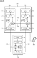
- FIG. 1 Industrial automation system shown simplified comprises a fail-safe control unit 200, in particular a programmable logic controller, with a primary control device 201 and a secondary control device 202.
- Programmable logic controllers usually each comprise a communication module, a central processing unit and at least one input / output unit.
- programmable logic controllers can be connected, for example, to a switch or router or to a fieldbus.
- Input / output units are used to exchange control and measured variables between programmable logic controllers and machines or devices 300 controlled by programmable logic controllers.
- the central units are provided, in particular, for determining suitable control variables from detected measured variables.
- the above components of programmable logic controllers are preferably connected to one another via a backplane bus system.
- the primary control device 201 and the secondary control device 202 are mutually redundant and each comprise a switching functional unit 211, 221 for processing a Internet Protocol stack, a transport function unit 214, 224 with multipath TCP functionality and a runtime environment 215, 225 for applications or control programs.
- the switching function units 211, 221 each access a communication network adapter of the respective control device via a communication network adapter driver.
- the communication network adapters in turn each comprise a transmitting and receiving unit and a control unit for coordinating access to a communication medium.
- the fail-safe control unit 200 is a highly available system. Typically, a system is considered to be highly available when an application provided by the system continues to be available even in the event of a system component failure and can continue to be used without direct human intervention. There should be no or only a minimal interruption perceptible to a user. If, for example, a control device 201, 202 of the fail-safe control unit 200 fails, there is a seamless switchover to the remaining control device. High availability of a system accordingly means to ensure unrestricted operation in the event of failure of one of its system components.
- the primary control device 201 and the secondary control device 202 have in the present embodiment, central units, which are designed for both an asynchronous coupling and for a synchronous coupling.
- control programs or program paths of the control programs in the primary control device 201 and in the secondary control device 202 are executed synchronously in time.
- both wait Control devices 201, 202 to a response of the other control device and only then continue their program processing.
- a master role can be assigned to the primary control device 201, while the secondary control device 202 can have a slave role. If the primary controller 201 fails under these conditions, the secondary controller 202 takes over the master role. So that the primary control device 201 and the secondary control device 202 can process their respective control programs or program paths asynchronously in time, they synchronize via synchronization connections 210, 220. On this basis, redundancy and monitoring functions are implemented. In a time-asynchronous processing of the control programs or program paths, the controller with slave role preferably passes only program paths that are released by the controller with master role.
- EP 2 657 797 A1 refer to.
- a communication device 100 which may be integrated, for example, in an automation device and is preferably connected via an Ethernet-based communication network with the fail-safe control unit 200.
- automation devices can be operator control and monitoring stations, programmable logic controllers, RFID readers or systems for machine vision.
- Operating and monitoring stations are used to visualize process data or measurement and control variables by programmable logic controllers, input / output units or sensors are processed or detected.
- operator control and monitoring stations are used to display values of a control loop and to change control parameters.
- Operator and observation stations include at least a graphical user interface, an input device, a processor unit and a communication module.
- the communication device 100 may for example also be assigned to an engineering system for configuring automation devices or a control system for monitoring automation devices or be a corresponding system component.
- the industrial automation system can also include network infrastructure devices, such as switches, routers or firewalls. These network infrastructure devices are used in particular for connecting programmable logic controllers, input / output units (I / O modules) or operating and monitoring stations of the industrial automation system. Input / output units may be configured as distributed peripheral modules located remotely from a programmable logic controller.
- control devices 201, 202 can also be redundantly operated server units of a cloud, edge or fog computing system.
- Such computing systems each include a plurality of server units that provide IT infrastructure, such as storage space, processing power or application software, as a service.
- the services provided by the server units may include applications or functions for system, process and device monitoring, device control and configuration, measurement and status information associated with automation device acquisition and analysis, and communication and automation functions.
- the communication device 100 may be, in particular, an edge computing client or a plant data hub.
- a variety of communication or automation devices can be connected to a cloud, edge or fog computing system via a plant data hub as a data distribution unit or network infrastructure device.
- Communication device 100 also includes a switching function unit 111 for processing an Internet protocol stack, a transport function unit 114 with multipath TCP functionality, and a runtime environment 115 for applications or control programs.
- the switching functional unit 111 accesses a communication network adapter of the communication device 100 via a communication network adapter driver.
- the communication network adapter in turn comprises a transmitting and receiving unit and a control unit for coordinating access to a communication medium.
- the transport function unit 114 of the communication device 100 establishes two communication connections to the fail-safe control unit 200 using at least one communication network address assigned to the primary control device 201 or the secondary control device 202.
- the primary control device 201 and the secondary control device 202 provide address information to the respective other control device in response to a request from a communication device to establish a communication connection.
- the communication device 100 initially only a communication address of one of the two control devices 201, 202 is present.
- the transport function unit 114 of the communication device 100 sets up a first communication connection 110 to the transport function unit 214 of the primary control device 201 and a second communication connection 120 to the transport function unit 224 of the secondary control device 201. In both cases this is done according to the Transmission Control Protocol.
- corresponding multipath TCP subflows 112-113, 212-213, 222-223 are generated by the transport function units 114, 214, 224 for the first communication connection 110 and the second communication connection 120.
- a first multipath TCP subflow 112, 212, 222 is generated for the first communication link 110, while a second multipath TCP subflow 113, 213, 223 is generated for the second communication link 120 in each case.
- Data transmitted via the first communication connection 110 are forwarded by the primary control device 201 via a first synchronization connection 210 to the secondary control device 202. Accordingly, data transmitted via the second communication link 220 is forwarded by the secondary controller 202 via a second synchronization link 220 to the primary controller 201.
- optical Ethernet transmission links are preferably used for the synchronization connections 210, 220.
- the transport function unit 214 of the primary control device 201 and the transport function unit 224 of the secondary control device 202 thus each manage a connection assigned to the first multipath TCP subflow 212, 222 and a connection assigned to the second multipath TCP subflow 213, 223.
- the transport function unit 224 of the secondary controller 202 arranges over the first synchronization connection 210 forwarded data of the first communication link 110 to the first multipath TCP subflow 222, while the transport function unit 214 of the primary control device 201 via the second synchronization link 220 forwarded data of the second communication link 120 the second multipath TCP subflow 213 assigns.
- the communication device 100 can continue to reach the fail-safe control unit 200 via the remaining communication link. This is ensured transparently on the basis of multipath TCP for applications running on the communication device 100 or on the control devices 201, 202. A failure or malfunction leads at most to a reduced data throughput.
- the two communication links 110, 120 can be loaded asymmetrically as a matter of principle in that one of the two multipath TCP subflows is set up only as a reserve and a data transmission takes place only via an actively used multipath TCP subflow.
- one of the two multipath TCP subflows is set up only as a reserve and a data transmission takes place only via an actively used multipath TCP subflow.
- initially only data is transmitted via the first communication connection 110, while the second communication connection 120 is set up as a standby connection. Only when the first communication connection 110 fails, data is transmitted via the second communication connection 120.
- load distribution methods can also be used for the two communication links 110, 120.
- load distribution methods can also be used for the two communication links 110, 120.
- Between the communication device 100 and the fail-safe control unit 200 to be transmitted Data segments selectively and load-dependent over the first communication link 110 or via the second communication link 120 transmitted.
- data segments to be transmitted between the communication device 100 and the fail-safe control unit 200 are divided into first data segments, which are transmitted only via the first communication link 110, and into second data segments, which are transmitted only via the second communication link 120.
- multipath TCP is also preferably used for the synchronization links 210, 220 between the primary controller 201 and the secondary controller 202.
- first synchronization connection 210 and the second synchronization connection 220 between corresponding multipath TCP subflows 212'-213 ', 222'-223' are generated, which are respectively managed by the transport function units 214, 224 of the control devices 201, 202.
- a use of multipath TCP for the synchronization connections 210, 220 is extremely advantageous in some operating states of a redundant automation system, in particular if considerable amounts of data have to be transmitted during a reintegration of a control device 201, 202. Since such processes should proceed as quickly as possible, a bundling of transmission rates of both synchronization connections is advantageous and leads to an improved system performance and to an increased availability.
Landscapes
- Engineering & Computer Science (AREA)
- Signal Processing (AREA)
- Computer Networks & Wireless Communication (AREA)
- Physics & Mathematics (AREA)
- General Physics & Mathematics (AREA)
- Automation & Control Theory (AREA)
- Quality & Reliability (AREA)
- Manufacturing & Machinery (AREA)
- General Engineering & Computer Science (AREA)
- Small-Scale Networks (AREA)
- Hardware Redundancy (AREA)
- Safety Devices In Control Systems (AREA)
- Data Exchanges In Wide-Area Networks (AREA)
Abstract
Description
- Industrielle Automatisierungssysteme dienen zur Überwachung, Steuerung und Regelung von technischen Prozessen, insbesondere im Bereich Fertigungs-, Prozess- und Gebäudeautomatisierung, und ermöglichen einen im wesentlichen selbständigen Betrieb von Steuerungseinrichtungen, Sensoren, Maschinen und technischen Anlagen. Eine wesentliche Grundlage für eine zuverlässige Bereitstellung von Überwachungs-, Steuerungs- und Regelungsfunktionen mittels eines Prozessautomatisierungssystems besteht in einer vollständigen und korrekten Erfassung und Abbildung von Komponenten des industriellen Prozessautomatisierungssystems in einem Engineering- bzw. Projektierungssystem.
- Unterbrechungen von Kommunikationsverbindungen zwischen Rechnereinheiten eines industriellen Automatisierungssystems oder Automatisierungsgeräten können zu einer unerwünschten oder unnötigen Wiederholung einer Übermittlung einer Dienstanforderung führen. Außerdem können nicht oder nicht vollständig übermittelte Nachrichten beispielsweise einen Übergang oder Verbleib eines industriellen Automatisierungssystems in einen sicheren Betriebszustand verhindern. Dies kann schließlich zu einem Ausfall einer kompletten Produktionsanlage und einem kostspieligen Produktionsstillstand führen. Eine besondere Problematik resultiert in industriellen Automatisierungssystemen regelmäßig aus einem Meldungsverkehr mit verhältnismäßig vielen, aber relativ kurzen Nachrichten, wodurch obige Probleme verstärkt werden.
- Aus
DE 10 2013 211 406 A1 ist bekannt, dass zur hochverfügbaren Anbindung von Automatisierungsgeräten mit vollständig unabhängigen Ethernet-Schnittstellen innerhalb eines redundanten Komunikationsnetzes an einfach angebundene Automatisierungsgeräte für das jeweilige einfach angebundene Automatisierungsgerät ein Y-Switch verwendet wird. Dabei ist der Y-Switch über einen ersten bzw. zweiten Port mit einem ersten bzw. Teilnetz des redundanten Kommunikationsnetzes verbunden, während er über einen dritten Port mittelbar oder unmittelbar mit dem einfach angebundenen Automatisierungsgerät verbunden ist. Darüber hinaus werden eingehende Datenrahmen am ersten, zweiten bzw. dritten Port einem ersten, zweiten bzw. dritten VLAN zugeordnet. Zusätzlich werden der erste bzw. zweite Port als Untagged Member für das erste und dritte VLAN bzw. für das zweite und dritte VLAN eingerichtet. Der dritte Port wird für alle drei VLANs als Untagged Member eingerichtet. An den ersten beiden Ports gelernte Unicast-MAC-Adressen werden automatisch als statischer Eintrag für das dritte VLAN übernommen. Bei Löschen einer an den ersten beiden Ports gelernten Unicast-MAC-Adresse erfolgt auch ein Löschen des korrespondierenden statischen Eintrags für das dritte VLAN. - Bei einer gesicherten Kommunikationsverbindung zu einem mit einem industriellen Automatisierungssystem verbundenen Kommunikationsgerät über ein ungesichertes Teilnetz überprüft eine Überwachungseinheit entsprechend
EP 3 001 647 B1 , ob eine neue dem Kommunikationsgerät für eine Verbindung zum ungesicherten Teilnetz zugeordnete Kommunikationsnetzadresse gültig wird. Die Überwachungseinheit übermittelt bei einem Wechsel einer Kommunikationsnetzadresse und einer noch bestehenden gesicherten Kommunikationsverbindung eine Adresswechselankündigung über die bestehende gesicherte Kommunikationsverbindung. Bei Empfang einer Adresswechselankündigung werden ein Aufbau einer zusätzlichen gesicherten Kommunikationsverbindung sowie eine Umschaltung von der bestehenden gesicherten Kommunikationsverbindung auf die zusätzliche gesicherte Kommunikationsverbindung eingeleitet. - In
EP 3 051 371 B1 ist ein Verfahren zum Aufbau einer unterbrechungsfreien Kommunikationsverbindung mit einem Kommunikationsgerät beschrieben, das einem industriellen Automatisierungssystem zugeordnet ist. Dabei überprüft eine dem Kommunikationsgerät zugeordnete Überwachungseinheit, ob eine zweite dem ersten Kommunikationsgerät zugeordnete Kommunikationsnetzadresse gültig wird. Bei Zuordnung einer neuen gültigen Kommunikationsnetzadresse und bestehender Kommunikationsverbindung initiiert die Überwachungseinheit einen Aufbau einer zusätzlichen Kommunikationsverbindung entsprechend Multipath-TCP (Transmission Control Protocol). -
EP 2 881 812 B1 betrifft ein Verfahren zum Betreiben einer Automatisierungseinrichtung, deren CPU-Modul dazu ausgebildet ist, lesend oder schreibend auf dezentrale Peripherie-Module zuzugreifen. Die dezentralen Peripherie-Module umfassen jeweils zwei Interface-Module, die jeweils mit einer Eingabe- und Ausgabe-Steuerung innerhalb einer Ringtopologie verbunden sind. Peripherie-Zugriffe werden über einen oder zwei Ringe ausgeführt werden. Mittels eines für jeden Ring vorgesehenen Redundanz-Managers wird der jeweilige Ring in einem Normalbetrieb logisch unterbrochen. Im Falle einer physikalischen Ringunterbrechung wird eine Ring-Rekonfiguration für den jeweiligen Ring eingeleitet. Aufgrund geeigneter Maßnahmen sind bereits während einer Ring-Rekonfiguration Peripheriezugriffe möglich. - Aus der älteren europäischen Patentanmeldung mit dem Anmeldeaktenzeichen
EP17181169.8 - Der vorliegenden Erfindung liegt die Aufgabe zugrunde, ein Verfahren zum Aufbau einer redundanten Kommunikationsverbindung zwischen einer ausfallgesicherten Steuerungseinheit mit redundanten Teilsystemen und einem Kommunikationsgerät zu schaffen, das eine von einer zunächst vorgegebenen Anzahl der redundanten Teilsysteme im wesentlichen unabhängige Kommunikation zwischen der ausfallgesicherten Steuerungseinheit und dem Kommunikationsgerät ermöglicht, sowie eine geeignete Vorrichtung zu dessen Durchführung anzugeben.
- Diese Aufgabe wird erfindungsgemäß durch ein Verfahren mit den in Anspruch 1 angegebenen Merkmalen und durch eine Steuerungseinheit mit den in Anspruch 15 angegebenen Merkmalen gelöst. Vorteilhafte Weiterbildungen der vorliegenden Erfindung sind in den abhängigen Patentansprüchen angegeben.
- Das erfindungsgemäße Verfahren ist zum Aufbau einer redundanten Kommunikationsverbindung zwischen einem Kommunikationsgerät und einer ausfallgesicherten Steuerungseinheit vorgesehen, die einem industriellen Automatisierungssystem zugeordnet ist und zumindest ein Primär-Steuerungsgerät sowie ein Sekundär-Steuerungsgerät umfasst. Dabei sind das Primär-Steuerungsgerät und das Sekundär-Steuerungsgerät zueinander redundant. Das Kommunikationsgerät kann beispielsweise Bestandteil eines Automatisierungsgeräts sein. Eine Transport- bzw. Vermittlungsfunktionseinheit des Kommunikationsgeräts baut unter Verwendung zumindest einer dem Primär-Steuerungsgerät bzw. dem Sekundär-Steuerungsgerät zugeordneten Kommunikationsnetzadresse zwei Kommunikationsverbindungen zur ausfallgesicherten Steuerungseinheit auf. Auf eine Anfrage eines Kommunikationsgeräts zum Aufbau einer Kommunikationsverbindung können das Primär-Steuerungsgerät und das Sekundär-Steuerungsgerät beispielsweise eine Adressinformation zum jeweils anderen Steuerungsgerät bereitstellen.
- Erfindungsgemäß baut die Transport- bzw. Vermittlungsfunktionseinheit des Kommunikationsgeräts eine erste Kommunikationsverbindung zu einer Transport- bzw. Vermittlungsfunktionseinheit des Primär-Steuerungsgeräts und eine zweite Kommunikationsverbindung zu einer Transport- bzw. Vermittlungsfunktionseinheit des Sekundär-Steuerungsgeräts auf. Vorteilhafterweise werden die erste Kommunikationsverbindung und die zweite Kommunikationsverbindung entsprechend Transmission Control Protocol aufgebaut. Über die erste Kommunikationsverbindung übermittelte Daten werden vom Primär-Steuerungsgerät über eine erste Synchronisationsverbindung an das Sekundär-Steuerungsgerät weitergeleitet. Dagegen werden über die zweite Kommunikationsverbindung übermittelte Daten vom Sekundär-Steuerungsgerät über eine zweite Synchronisationsverbindung an das Primär-Steuerungsgerät weitergeleitet. Auf diese Weise können einfach und zuverlässig skalierbare redundante Kommunikationsverbindungen zu einer ausfallgesicherten Steuerungseinheit aufgebaut werden.
- Entsprechend einer bevorzugten Ausgestaltung der vorliegenden Erfindung weisen die Transport- bzw. Vermittlungsfunktionseinheit des Primär-Steuerungsgeräts und die Transport- bzw. Vermittlungsfunktionseinheit des Sekundär-Steuerungsgeräts jeweils eine Multipath-TCP-Funktionalität auf. Dementsprechend weist auch die Transport- bzw. Vermittlungsfunktionseinheit des Kommunikationsgeräts eine Multipath-TCP-Funktionalität auf. Vorteilhafterweise werden die erste Kommunikationsverbindung und die zweite Kommunikationsverbindung jeweils als korrespondierende Multipath-TCP-Subflows aufgebaut. Dabei ist die erste Kommunikationsverbindung ein erster Multipath-TCP-Subflow, während die zweite Kommunikationsverbindung ein zweiter Multipath-TCP-Subflow ist. Vorzugsweise werden auch die erste Synchronisationsverbindung und die zweite Synchronisationsverbindung zwischen dem Primär-Steuerungsgerät und dem Sekundär-Steuerungsgerät als korrespondierende Multipath-TCP-Subflows aufgebaut.
- Die Transport- bzw. Vermittlungsfunktionseinheit des Primär-Steuerungsgeräts und die Transport- bzw. Vermittlungsfunktionseinheit des Sekundär-Steuerungsgeräts verwalten entsprechend einer besonders bevorzugten Ausgestaltung der vorliegenden Erfindung jeweils sowohl eine dem ersten Multipath-TCP-Subflow zugeordnete Verbindung als auch eine dem zweiten Multipath-TCP-Subflow zugeordnete Verbindung. Insbesondere ordnet die Transport- bzw. Vermittlungsfunktionseinheit des Sekundär-Steuerungsgeräts entsprechend einer weiteren Ausgestaltung über die erste Synchronisationsverbindung weitergeleitete Daten der ersten Kommunikationsverbindung dem ersten Multipath-TCP-Subflow zu. Dementsprechend ordnet die Transport- bzw. Vermittlungsfunktionseinheit des Primär-Steuerungsgeräts über die zweite Synchronisationsverbindung weitergeleitete Daten der zweiten Kommunikationsverbindung dem zweiten Multipath-TCP-Subflow zu.
- Entsprechend einer alternativen Weiterbildung der vorliegenden Erfindung werden zunächst nur über die erste Kommunikationsverbindung Daten übermittelt, wobei die zweite Kommunikationsverbindung als Standby-Verbindung aufgebaut wird. Erst bei einem Ausfall der ersten Kommunikationsverbindung werden in diesem Fall Daten über die zweite Kommunikationsverbindung übermittelt. Entsprechend einer weiteren alternativen Weiterbildung der vorliegenden Erfindung werden zwischen dem Kommunikationsgerät und der ausfallgesicherten Steuerungseinheit zu übermittelnde Datensegmente alternierend über die erste Kommunikationsverbindung oder über die zweite Kommunikationsverbindung übermittelt. Insbesondere werden dabei zwischen dem Kommunikationsgerät und der ausfallgesicherten Steuerungseinheit zu übermittelnde Datensegmente in erste Datensegmente, die nur über die erste Kommunikationsverbindung übermittelt werden, und in zweite Datensegmente unterteilt, die nur über die zweite Kommunikationsverbindung übermittelt werden. Dies kann beispielsweise abhängig von einer Auslastung der Kommunikationsverbindungen erfolgen.
- Die Transport- bzw. Vermittlungsfunktionseinheiten der Steuerungsgeräte bzw. des Kommunikationsgeräts sind insbesondere zur Verarbeitung eines Internetprotokollstapels ausgestaltet und eingerichtet. Beispielsweise können die Transport- bzw. Vermittlungsfunktionseinheiten in das Kommunikationsgerät bzw. in die Steuerungsgeräte integriert sein, wobei die Transport- bzw. Vermittlungsfunktionseinheiten jeweils über einen Kommunikationsnetzadapter-Treiber auf einen Kommunikationsnetzadapter des Kommunikationsgeräts bzw. der Steuerungsgeräte zugreifen. Die Kommunikationsnetzadapter umfassen insbesondere jeweils eine Sende- und Empfangseinheit und eine Steuerungseinheit zur Koordination eines Zugriffs auf ein Kommunikationsmedium.
- Die erfindungsgemäße ausfallgesicherte Steuerungseinheit ist zur Durchführung eines Verfahrens entsprechend vorangehenden Ausführungen vorgesehen und umfasst zumindest ein Primär-Steuerungsgerät sowie ein Sekundär-Steuerungsgerät. Das Primär-Steuerungsgerät und das Sekundär-Steuerungsgerät sind zueinander redundant und umfassen jeweils eine Transport- bzw. Vermittlungsfunktionseinheit. Außerdem ist die ausfallgesicherte Steuerungseinheit dafür ausgestaltet und eingerichtet ist, dass eine Transport- bzw. Vermittlungsfunktionseinheit eines Kommunikationsgeräts unter Verwendung zumindest einer dem Primär-Steuerungsgerät bzw. dem Sekundär-Steuerungsgerät zugeordneten Kommunikationsnetzadresse zwei Kommunikationsverbindungen zur ausfallgesicherten Steuerungseinheit aufbaut.
- Erfindungsgemäß ist die ausfallgesicherte Steuerungseinheit dafür ausgestaltet und eingerichtet, dass über eine erste Kommunikationsverbindung zwischen dem Kommunikationsgerät und dem Primär-Steuerungsgerät übermittelte Daten vom Primär-Steuerungsgerät über eine erste Synchronisationsverbindung an das Sekundär-Steuerungsgerät weitergeleitet werden. Darüber hinaus ist die ausfallgesicherte Steuerungseinheit dafür ausgestaltet und eingerichtet, dass über eine zweite Kommunikationsverbindung zwischen dem Kommunikationsgerät und dem Sekundär-Steuerungsgerät übermittelte Daten vom Sekundär-Steuerungsgerät über eine zweite Synchronisationsverbindung an das Primär-Steuerungsgerät weitergeleitet werden.
- Die vorliegende Erfindung wird nahfolgend an einem Ausführungsbeispiel anhand der Zeichnung näher beschrieben. Es zeigt
- Figur 1
- ein industrielles Automatisierungssystem mit zumindest einer ausfallgesicherten Steuerungseinheit und einem mit dieser kommunizierenden Kommunikationsgerät,
- Figur 2
- eine Detaildarstellung einer Synchronisation innerhalb der ausfallgesicherten Steuerungseinheit.
- Das in
Figur 1 vereinfacht dargestellte industrielle Automatisierungssystem umfasst eine ausfallgesicherte Steuerungseinheit 200, insbesondere eine speicherprogrammierbare Steuerung, mit einem Primär-Steuerungsgerät 201 und einem Sekundär-Steuerungsgerät 202. Speicherprogrammierbare Steuerungen umfassen üblicherweise jeweils ein Kommunikationsmodul, eine Zentraleinheit sowie zumindest eine Eingabe/Ausgabe-Einheit. Über Kommunikationsmodule können speicherprogrammierbare Steuerungen beispielsweise mit einem Switch oder Router oder mit einem Feldbus verbunden werden. Eingabe/Ausgabe-Einheiten dienen einem Austausch von Steuerungs- und Messgrößen zwischen speicherprogrammierbaren Steuerungen und durch speicherprogrammierbare Steuerungen gesteuerten Maschinen oder Vorrichtungen 300. Die Zentraleinheiten sind insbesondere für eine Ermittlung geeigneter Steuerungsgrößen aus erfassten Messgrößen vorgesehen. Obige Komponenten speicherprogrammierbarer Steuerungen werden vorzugsweise über ein Rückwandbus-System miteinander verbunden. - Das Primär-Steuerungsgerät 201 und das Sekundär-Steuerungsgerät 202 sind zueinander redundant und umfassen jeweils eine Vermittlungsfunktionseinheit 211, 221 zur Verarbeitung eines Internetprotokollstapels, eine Transportfunktionseinheit 214, 224 mit Multipath-TCP-Funktionalität und eine Laufzeitumgebung 215, 225 für Anwendungen bzw. Steuerungsprogramme. Die Vermittlungsfunktionseinheiten 211, 221 greifen jeweils über einen Kommunikationsnetzadapter-Treiber auf einen Kommunikationsnetzadapter des jeweiligen Steuerungsgeräts zu. Die Kommunikationsnetzadapter umfassen wiederum jeweils eine Sende- und Empfangseinheit und eine Steuerungseinheit zur Koordination eines Zugriffs auf ein Kommunikationsmedium.
- Im vorliegenden Ausführungsbeispiel handelt es sich bei der ausfallgesicherten Steuerungseinheit 200 um ein hochverfügbares System. Üblicherweise gilt ein System dann als hochverfügbar, wenn eine durch das System bereitgestellte Anwendung auch bei einem Ausfall einer Systemkomponente weiterhin verfügbar ist und ohne unmittelbaren menschlichen Eingriff weiter genutzt werden kann. Dabei sollte für einen Anwender keine oder nur eine minimale Unterbrechung wahrnehmbar sein. Fällt beispielsweise ein Steuerungsgerät 201, 202 der ausfallgesicherten Steuerungseinheit 200 aus, erfolgt ein nahtloses Umschalten auf das verbleibende Steuerungsgerät. Hochverfügbarkeit eines Systems bedeutet dementsprechend, bei Ausfall einer seiner Systemkomponente einen uneingeschränkten Betrieb zu gewährleisten.
- Das Primär-Steuerungsgerät 201 und das Sekundär-Steuerungsgerät 202 weisen im vorliegenden Ausführungsbeispiel Zentraleinheiten auf, die sowohl für eine asynchrone Kopplung als auch für eine synchrone Kopplung ausgebildet sind. Bei einer synchronen Kopplung werden Steuerungsprogramme bzw. Programmpfade der Steuerungsprogramme im Primär-Steuerungsgerät 201 und im Sekundär-Steuerungsgerät 202 zeitlich synchron durchlaufen. An Programmstellen, an denen ein Abgleich zwischen beiden Steuerungsgeräten 201, 202 vorgesehen ist, warten beide Steuerungsgeräte 201, 202 auf eine Antwort des jeweils anderen Steuerungsgeräts und setzen erst dann jeweils ihre Programmverarbeitung fort.
- Für eine asynchrone Kopplung kann dem Primär-Steuerungsgerät 201 beispielsweise eine Master-Rolle zugeordnet werden, während das Sekundär-Steuerungsgerät 202 eine Slave-Rolle haben kann. Falls das Primär-Steuerungsgerät 201 unter diesen Voraussetzungen ausfällt, übernimmt das Sekundär-Steuerungsgerät 202 die Master-Rolle. Damit das Primär-Steuerungsgerät 201 und das Sekundär-Steuerungsgerät 202 ihre jeweiligen Steuerungsprogramme bzw. Programmpfade zeitlich asynchron verarbeiten können, synchronisieren sie sich über Synchronisationsverbindungen 210, 220. Auf dieser Basis werden Redundanz- und Überwachungsfunktionen realisiert. Bei einer zeitlich asynchronen Verarbeitung der Steuerungsprogramme bzw. Programmpfade durchläuft das Steuerungsgerät mit Slave-Rolle vorzugsweise nur Programmpfade, die durch das Steuerungsgerät mit Master-Rolle freigegeben sind. Eine detaillierte Beschreibung zur asynchronen Kopplung ist
EP 2 657 797 A1 zu entnehmen. - Neben der ausfallgesicherten Steuerungseinheit 200 umfasst das in
Figur 1 dargestellte industrielle Automatisierungssystem ein Kommunikationsgerät 100, das beispielsweise in ein Automatisierungsgerät integriert sein kann und vorzugsweise über ein Ethernet-basiertes Kommunikationsnetz mit der ausfallgesicherten Steuerungseinheit 200 verbunden ist. Automatisierungsgeräte können insbesondere Bedien- und Beobachtungsstationen, speicherprogrammierbare Steuerungen, RFID-Lesegeräte oder Systeme für maschinelle Bildverarbeitung sein. Bedien- und Beobachtungsstationen dienen zur Visualisierung von Prozessdaten bzw. Mess- und Steuerungsgrößen, die durch speicherprogrammierbare Steuerungen, Eingabe/Ausgabe-Einheiten oder Sensoren verarbeitet bzw. erfasst werden. Insbesondere werden Bedien- und Beobachtungsstationen zur Anzeige von Werten eines Regelungskreises und zur Veränderung von Regelungsparametern verwendet. Bedien- und Beobachtungsstationen umfassen zumindest eine graphische Benutzerschnittstelle, ein Eingabegerät, eine Prozessoreinheit und ein Kommunikationsmodul. Darüber hinaus kann das Kommunikationsgerät 100 beispielsweise auch einem Engineering-System zur Projektierung von Automatisierungsgeräten oder einem Leitsystem zur Überwachung von Automatisierungsgeräten zugeordnet bzw. eine entsprechende Systemkomponente sein. - Neben Automatisierungsgeräten kann das industrielle Automatisierungssystem auch Netzinfrastrukturgeräte, wie Switche, Router oder Firewalls, umfassen. Diese Netzinfrastrukturgeräte dienen insbesondere zum Anschluss von speicherprogrammierbaren Steuerungen, Eingabe/Ausgabe-Einheiten (I/O-Module) oder Bedien- und Beobachtungsstationen des industriellen Automatisierungssystems. Eingabe/Ausgabe-Einheiten können als dezentrale Peripheriemodule ausgestaltet sein, die entfernt von einer speicherprogrammierbaren Steuerung angeordnet sind.
- Grundsätzlich können die Steuerungsgeräte 201, 202 auch redundant betriebene Servereinheiten eines Cloud-, Edge- oder Fog-Computing-Systems sein. Derartige Computing-Systeme umfassen jeweils mehrere Servereinheiten, durch die IT-Infrastruktur, wie Speicherplatz, Rechenleistung oder Anwendungssoftware, als Dienst bereitgestellt wird. Insbesondere können die durch die Servereinheiten bereitgestellten Dienste Anwendungen bzw. Funktionen zur System-, Prozess- und Geräteüberwachung, zur Gerätesteuerung und -konfiguration, zur Erfassung und Analyse von Automatisierungsgeräten zugeordneten Messwerten und Zustandsinformationen sowie Kommunikations- und Automatisierungsfunktionen umfassen.
- Im Zusammenhang mit redundant betriebenen Servereinheiten eines Cloud-, Edge- oder Fog-Computing-Systems kann das Kommunikationsgerät 100 insbesondere ein Edge-Computing-Client oder ein Plant-Data-Hub sein. Über einen Plant-Data-Hub als Datenverteilereinheit bzw. Netzinfrastrukturgerät kann eine Vielzahl von Kommunikations- oder Automatisierungsgeräten an ein Cloud-, Edge- oder Fog-Computing-Systems angebunden werden.
- Auch Kommunikationsgerät 100 umfasst eine Vermittlungsfunktionseinheit 111 zur Verarbeitung eines Internetprotokollstapels, eine Transportfunktionseinheit 114 mit Multipath-TCP-Funktionalität und eine Laufzeitumgebung 115 für Anwendungen bzw. Steuerungsprogramme. Analog zu obigen Ausführungen greift die Vermittlungsfunktionseinheit 111 über einen Kommunikationsnetzadapter-Treiber auf einen Kommunikationsnetzadapter des Kommunikationsgeräts 100 zu. Der Kommunikationsnetzadapter umfasst wiederum eine Sende- und Empfangseinheit und eine Steuerungseinheit zur Koordination eines Zugriffs auf ein Kommunikationsmedium.
- Die Transportfunktionseinheit 114 des Kommunikationsgeräts 100 baut unter Verwendung zumindest einer dem Primär-Steuerungsgerät 201 bzw. dem Sekundär-Steuerungsgerät 202 zugeordneten Kommunikationsnetzadresse zwei Kommunikationsverbindungen zur ausfallgesicherten Steuerungseinheit 200 auf. Vorteilhafterweise stellen das Primär-Steuerungsgerät 201 und das Sekundär-Steuerungsgerät 202 auf eine Anfrage eines Kommunikationsgeräts zum Aufbau einer Kommunikationsverbindung eine Adressinformation zum jeweils anderen Steuerungsgerät bereit. Damit ist es ausreichend, wenn dem Kommunikationsgerät 100 zunächst nur eine Kommunikationsadresse eines der beiden Steuerungsgeräte 201, 202 vorliegt.
- Die Transportfunktionseinheit 114 des Kommunikationsgeräts 100 baut eine erste Kommunikationsverbindung 110 zur Transportfunktionseinheit 214 des Primär-Steuerungsgeräts 201 und eine zweite Kommunikationsverbindung 120 zur Transportfunktionseinheit 224 des Sekundär-Steuerungsgeräts 201 auf. In beiden Fällen erfolgt dies entsprechend Transmission Control Protocol. Dabei werden durch die Transportfunktionseinheiten 114, 214, 224 für die erste Kommunikationsverbindung 110 und die zweite Kommunikationsverbindung 120 jeweils korrespondierende Multipath-TCP-Subflows 112-113, 212-213, 222-223 erzeugt. Für die erste Kommunikationsverbindung 110 wird jeweils ein erster Multipath-TCP-Subflow 112, 212, 222, erzeugt, während für die zweite Kommunikationsverbindung 120 jeweils ein zweiter Multipath-TCP-Subflow 113, 213, 223 erzeugt wird.
- Über die erste Kommunikationsverbindung 110 übermittelte Daten werden vom Primär-Steuerungsgerät 201 über eine erste Synchronisationsverbindung 210 an das Sekundär-Steuerungsgerät 202 weitergeleitet. Dementsprechend werden über die zweite Kommunikationsverbindung 220 übermittelte Daten vom Sekundär-Steuerungsgerät 202 über eine zweite Synchronisationsverbindung 220 an das Primär-Steuerungsgerät 201 weitergeleitet. Für die Synchronisationsverbindungen 210, 220 werden vorzugsweise optische Ethernet-Übertragungsstecken verwendet.
- Die Transportfunktionseinheit 214 des Primär-Steuerungsgeräts 201 und die Transportfunktionseinheit 224 des Sekundär-Steuerungsgeräts 202 verwalten somit jeweils eine dem ersten Multipath-TCP-Subflow 212, 222 zugeordnete Verbindung und eine dem zweiten Multipath-TCP-Subflow 213, 223 zugeordnete Verbindung. Insbesondere ordnet die Transportfunktionseinheit 224 des Sekundär-Steuerungsgeräts 202 über die erste Synchronisationsverbindung 210 weitergeleitete Daten der ersten Kommunikationsverbindung 110 dem ersten Multipath-TCP-Subflow 222 zu, während die Transportfunktionseinheit 214 des Primär-Steuerungsgeräts 201 über die zweite Synchronisationsverbindung 220 weitergeleitete Daten der zweiten Kommunikationsverbindung 120 dem zweiten Multipath-TCP-Subflow 213 zuordnet.
- Fällt eines der beiden Steuerungsgeräte 201, 202, oder ist eine Datenübermittlung auf einer der beiden Kommunikationsverbindungen 110, 120 gestört, so kann das Kommunikationsgerät 100 die ausfallgesicherte Steuerungseinheit 200 über die verbleibende Kommunikationsverbindung weiterhin erreichen. Dies wird für auf dem Kommunikationsgerät 100 bzw. auf den Steuerungsgeräten 201, 202 ablaufende Anwendungen transparent auf Basis von Multipath-TCP sichergestellt. Ein Ausfall oder eine Störung führt allenfalls zu einem reduzierten Datendurchsatz.
- Darüber hinaus können die beiden Kommunikationsverbindungen 110, 120 grundsätzlich asymmetrisch belastet werden, indem einer der beiden Multipath-TCP-Subflows lediglich als Reserve aufgebaut wird und eine Datenübermittlung nur über einen aktiv genutzten Multipath-TCP-Subflow erfolgt. In einem solchen Fall werden beispielsweise zunächst nur über die erste Kommunikationsverbindung 110 Daten übermittelt, während die zweite Kommunikationsverbindung 120 als Standby-Verbindung aufgebaut wird. Erst bei einem Ausfall der ersten Kommunikationsverbindung 110 werden Daten über die zweite Kommunikationsverbindung 120 übermittelt.
- Außerdem können auch für die beiden Kommunikationsverbindungen 110, 120 auch Lastverteilungsverfahren genutzt werden. Beispielsweise werden zwischen dem Kommunikationsgerät 100 und der ausfallgesicherten Steuerungseinheit 200 zu übermittelnde Datensegmente wahlweise und lastabhängig über die erste Kommunikationsverbindung 110 oder über die zweite Kommunikationsverbindung 120 übermittelt. Hierzu werden zwischen dem Kommunikationsgerät 100 und der ausfallgesicherte Steuerungseinheit 200 zu übermittelnde Datensegmente in erste Datensegmente, die nur über die erste Kommunikationsverbindung 110 übermittelt werden, und in zweite Datensegmente unterteilt, die nur über die zweite Kommunikationsverbindung 120 übermittelt werden,.
- Entsprechend
Figur 2 wird Multipath-TCP vorzugsweise auch für die Synchronisationsverbindungen 210, 220 zwischen dem Primär-Steuerungsgerät 201 und dem Sekundär-Steuerungsgerät 202 genutzt. Dabei werden für die erste Synchronisationsverbindung 210 und die zweite Synchronisationsverbindung 220 zwischen korrespondierende Multipath-TCP-Subflows 212'-213', 222'-223' erzeugt, die jeweils von den Transportfunktionseinheiten 214, 224 der Steuerungsgeräte 201, 202 verwaltet werden. Eine Verwendung von Multipath-TCP für die Synchronisationsverbindungen 210, 220 ist in einigen Betriebszuständen eines redundanten Automatisierungssystems äußerst vorteilhaft, insbesondere wenn bei einer Reintegration eines Steuerungsgeräts 201, 202 erhebliche Datenmengen zu übertragen sind. Da derartige Vorgänge möglichst schnell ablaufen sollen, ist eine Bündelung von Übertragungsraten beider Synchronisationsverbindungen vorteilhaft und führt zu einer verbesserten System-Performance sowie zu einer gesteigerten Verfügbarkeit.
Claims (15)
- Verfahren zum Aufbau einer redundanten Kommunikationsverbindung zwischen einem Kommunikationsgerät und einer ausfallgesicherten Steuerungseinheit, bei dem- die ausfallgesicherte Steuerungseinheit (200) einem industriellen Automatisierungssystem zugeordnet ist und zumindest ein Primär-Steuerungsgerät (201) sowie ein Sekundär-Steuerungsgerät (202) umfasst,- das Primär-Steuerungsgerät und das Sekundär-Steuerungsgerät zueinander redundant sind,- eine Transport- und/oder Vermittlungsfunktionseinheit (111, 114) des Kommunikationsgeräts (100) unter Verwendung zumindest einer dem Primär-Steuerungsgerät und/oder dem Sekundär-Steuerungsgerät zugeordneten Kommunikationsnetzadresse zwei Kommunikationsverbindungen zur ausfallgesicherten Steuerungseinheit aufbaut,- wobei die Transport- und/oder Vermittlungsfunktionseinheit des Kommunikationsgeräts eine erste Kommunikationsverbindung (110) zu einer Transport- und/oder Vermittlungsfunktionseinheit (211, 214) des Primär-Steuerungsgeräts und eine zweite Kommunikationsverbindung (120) zu einer Transport- und/oder Vermittlungsfunktionseinheit (221, 224) des Sekundär-Steuerungsgeräts aufbaut,- über die erste Kommunikationsverbindung übermittelte Daten vom Primär-Steuerungsgerät über eine erste Synchronisationsverbindung (210) an das Sekundär-Steuerungsgerät weitergeleitet werden,- über die zweite Kommunikationsverbindung übermittelte Daten vom Sekundär-Steuerungsgerät über eine zweite Synchronisationsverbindung (220) an das Primär-Steuerungsgerät weitergeleitet werden.
- Verfahren nach Anspruch 1,
bei dem die erste Kommunikationsverbindung (110) und die zweite Kommunikationsverbindung (120) entsprechend Transmission Control Protocol aufgebaut werden. - Verfahren nach Anspruch 2,
bei dem die Transport- und/oder Vermittlungsfunktionseinheit des Primär-Steuerungsgeräts und die Transport- und/oder Vermittlungsfunktionseinheit des Sekundär-Steuerungsgeräts jeweils eine Multipath-TCP-Funktionalität aufweisen und bei dem die Transport- und/oder Vermittlungsfunktionseinheit des Kommunikationsgeräts eine Multipath-TCP-Funktionalität aufweist. - Verfahren nach Anspruch 3,
bei dem die erste Kommunikationsverbindung und die zweite Kommunikationsverbindung jeweils als korrespondierende Multipath-TCP-Subflows (112-113, 212-213, 222-223) aufgebaut werden, bei dem die erste Kommunikationsverbindung ein erster Multipath-TCP-Subflow ist und bei dem die zweite Kommunikationsverbindung ein zweiter Multipath-TCP-Subflow ist. - Verfahren nach Anspruch 4,
bei dem die Transport- und/oder Vermittlungsfunktionseinheit des Primär-Steuerungsgeräts und die Transport- und/oder Vermittlungsfunktionseinheit des Sekundär-Steuerungsgeräts jeweils eine dem ersten Multipath-TCP-Subflow zugeordnete Verbindung und eine dem zweiten Multipath-TCP-Subflow zugeordnete Verbindung verwalten. - Verfahren nach Anspruch 5,
bei dem die Transport- und/oder Vermittlungsfunktionseinheit des Sekundär-Steuerungsgeräts über die erste Synchronisationsverbindung weitergeleitete Daten der ersten Kommunikationsverbindung dem ersten Multipath-TCP-Subflow zuordnet und bei dem die Transport- und/oder Vermittlungsfunktionseinheit des Primär-Steuerungsgeräts über die zweite Synchronisationsverbindung weitergeleitete Daten der zweiten Kommunikationsverbindung dem zweiten Multipath-TCP-Subflow zuordnet. - Verfahren nach einem der Ansprüche 1 bis 6,
bei dem zunächst nur über die erste Kommunikationsverbindung Daten übermittelt werden, bei dem die zweite Kommunikationsverbindung als Standby-Verbindung aufgebaut wird und bei dem erst bei einem Ausfall der ersten Kommunikationsverbindung Daten über die zweite Kommunikationsverbindung übermittelt werden. - Verfahren nach einem der Ansprüche 1 bis 6,
bei dem zwischen dem Kommunikationsgerät und der ausfallgesicherten Steuerungseinheit zu übermittelnde Datensegmente alternierend über die erste Kommunikationsverbindung oder über die zweite Kommunikationsverbindung übermittelt werden. - Verfahren nach Anspruch 8,
bei dem zwischen dem Kommunikationsgerät und der ausfallgesicherten Steuerungseinheit zu übermittelnde Datensegmente in erste Datensegmente, die nur über die erste Kommunikationsverbindung übermittelt werden, und in zweite Datensegmente, die nur über die zweite Kommunikationsverbindung übermittelt werden, unterteilt werden. - Verfahren nach einem der Ansprüche 1 bis 9,
bei dem die erste Synchronisationsverbindung und die zweite Synchronisationsverbindung zwischen dem Primär-Steuerungsgerät und dem Sekundär-Steuerungsgerät als korrespondierende Multipath-TCP-Subflows aufgebaut werden. - Verfahren nach einem der Ansprüche 1 bis 10,
bei dem das Primär-Steuerungsgerät und das Sekundär-Steuerungsgerät auf eine Anfrage eines Kommunikationsgeräts zum Aufbau einer Kommunikationsverbindung eine Adressinformation zum jeweils anderen Steuerungsgerät bereitstellen. - Verfahren nach einem der Ansprüche 1 bis 11,
bei dem die Transport- und/oder Vermittlungsfunktionseinheiten zur Verarbeitung eines Internetprotokollstapels ausgestaltet und eingerichtet sind. - Verfahren nach einem der Ansprüche 1 bis 12,
bei dem die Transport- und/oder Vermittlungsfunktionseinheiten in das Kommunikationsgerät und/oder in die Steuerungsgeräte integriert sind und bei dem die Transport- und/oder Vermittlungsfunktionseinheiten jeweils über einen Kommunikationsnetzadapter-Treiber auf einen Kommunikationsnetzadapter des Kommunikationsgeräts und/oder der Steuerungsgeräte zugreifen. - Verfahren nach Anspruch 13,
bei dem die Kommunikationsnetzadapter jeweils eine Sende- und Empfangseinheit und eine Steuerungseinheit zur Koordination eines Zugriffs auf ein Kommunikationsmedium umfassen. - Ausfallgesicherte Steuerungseinheit zur Durchführung eines Verfahrens nach einem der Ansprüche 1 bis 14,- wobei die ausfallgesicherte Steuerungseinheit (200) zumindest ein Primär-Steuerungsgerät (201) sowie ein Sekundär-Steuerungsgerät (202) umfasst,- wobei das Primär-Steuerungsgerät und das Sekundär-Steuerungsgerät zueinander redundant sind und jeweils eine Transport- und/oder Vermittlungsfunktionseinheit (211, 214; 221, 224) umfassen,- wobei die ausfallgesicherte Steuerungseinheit dafür ausgestaltet und eingerichtet ist, dass eine Transport- und/oder Vermittlungsfunktionseinheit (111, 114) eines Kommunikationsgeräts (100) unter Verwendung zumindest einer dem Primär-Steuerungsgerät und/oder dem Sekundär-Steuerungsgerät zugeordneten Kommunikationsnetzadresse zwei Kommunikationsverbindungen zur ausfallgesicherten Steuerungseinheit aufbaut,- wobei die ausfallgesicherte Steuerungseinheit dafür ausgestaltet und eingerichtet ist, dass über eine erste Kommunikationsverbindung (110) zwischen dem Kommunikationsgerät und dem Primär-Steuerungsgerät übermittelte Daten vom Primär-Steuerungsgerät über eine erste Synchronisationsverbindung (210) an das Sekundär-Steuerungsgerät weitergeleitet werden,- wobei die ausfallgesicherte Steuerungseinheit dafür ausgestaltet und eingerichtet ist, dass über eine zweite Kommunikationsverbindung (120) zwischen dem Kommunikationsgerät und dem Sekundär-Steuerungsgerät übermittelte Daten vom Sekundär-Steuerungsgerät über eine zweite Synchronisationsverbindung (220) an das Primär-Steuerungsgerät weitergeleitet werden.
Priority Applications (3)
| Application Number | Priority Date | Filing Date | Title |
|---|---|---|---|
| EP18164975.7A EP3547618B1 (de) | 2018-03-29 | 2018-03-29 | Verfahren zum aufbau einer redundanten kommunikationsverbindung und ausfallgesicherte steuerungseinheit |
| CN201910246821.6A CN110320793B (zh) | 2018-03-29 | 2019-03-28 | 用于构建冗余通信连接的方法和故障安全的控制单元 |
| US16/369,171 US11281190B2 (en) | 2018-03-29 | 2019-03-29 | Method for setting up a redundant communication connection, and failsafe control unit |
Applications Claiming Priority (1)
| Application Number | Priority Date | Filing Date | Title |
|---|---|---|---|
| EP18164975.7A EP3547618B1 (de) | 2018-03-29 | 2018-03-29 | Verfahren zum aufbau einer redundanten kommunikationsverbindung und ausfallgesicherte steuerungseinheit |
Publications (2)
| Publication Number | Publication Date |
|---|---|
| EP3547618A1 true EP3547618A1 (de) | 2019-10-02 |
| EP3547618B1 EP3547618B1 (de) | 2023-03-01 |
Family
ID=61906620
Family Applications (1)
| Application Number | Title | Priority Date | Filing Date |
|---|---|---|---|
| EP18164975.7A Active EP3547618B1 (de) | 2018-03-29 | 2018-03-29 | Verfahren zum aufbau einer redundanten kommunikationsverbindung und ausfallgesicherte steuerungseinheit |
Country Status (3)
| Country | Link |
|---|---|
| US (1) | US11281190B2 (de) |
| EP (1) | EP3547618B1 (de) |
| CN (1) | CN110320793B (de) |
Cited By (1)
| Publication number | Priority date | Publication date | Assignee | Title |
|---|---|---|---|---|
| CN115145188A (zh) * | 2021-03-30 | 2022-10-04 | 西门子股份公司 | 具有优化传输时间的高可用性的基于云的自动化方案 |
Families Citing this family (8)
| Publication number | Priority date | Publication date | Assignee | Title |
|---|---|---|---|---|
| EP3758301B1 (de) * | 2019-06-25 | 2022-05-04 | KNORR-BREMSE Systeme für Nutzfahrzeuge GmbH | Vorrichtung und verfahren zur bereitstellung einer redundanten kommunikation in einer fahrzeugarchitektur und entsprechende steuerarchitektur |
| EP3800517B1 (de) | 2019-10-04 | 2024-08-14 | Siemens Aktiengesellschaft | Verfahren zur erstellung eines redundanten automatisierungssystems, computerprogramm und computerlesbares medium |
| CN113809924B (zh) * | 2020-06-12 | 2025-03-07 | 平高集团有限公司 | 一种多级单元通讯同步的电力电子变压器 |
| DE102020117632B4 (de) * | 2020-07-03 | 2022-03-03 | Krohne Messtechnik Gmbh | Bussystem für eine Prozessanlage |
| EP3940467A1 (de) * | 2020-07-13 | 2022-01-19 | Siemens Aktiengesellschaft | Steuerungssystem zur steuerung einer vorrichtung oder anlage |
| US11768479B2 (en) * | 2020-09-30 | 2023-09-26 | Rockwell Automation Technologies, Inc. | System and method for secure connections in a high availability industrial controller |
| CN113433866A (zh) * | 2021-07-13 | 2021-09-24 | 深圳市越疆科技有限公司 | 安全控制系统 |
| EP4495712A1 (de) * | 2023-07-19 | 2025-01-22 | Siemens Aktiengesellschaft | Redundantes automatisierungssystem und verfahren zum betrieb |
Citations (9)
| Publication number | Priority date | Publication date | Assignee | Title |
|---|---|---|---|---|
| US5202822A (en) * | 1990-09-26 | 1993-04-13 | Honeywell Inc. | Universal scheme of input/output redundancy in a process control system |
| US20090265493A1 (en) * | 2008-04-16 | 2009-10-22 | Mendu Krishna R | Efficient Architecture for Interfacing Redundant Devices to a Distributed Control System |
| US20100030937A1 (en) * | 2006-10-02 | 2010-02-04 | Martin Schuermann | Method and system for redundantly controlling a slave device |
| EP2547045A1 (de) * | 2011-07-15 | 2013-01-16 | Yokogawa Electric Corporation | Feldkommunikationssystem |
| EP2657797A1 (de) | 2012-04-27 | 2013-10-30 | Siemens Aktiengesellschaft | Verfahren zum Betreiben eines redundanten Automatisierungssystems |
| DE102013211406A1 (de) | 2013-06-18 | 2014-12-18 | Siemens Aktiengesellschaft | Kommunikationsgerät zur Verbindung eines Feldgeräts eines industriellen Automatisierungssystems mit einer ausfallgesicherten Steuerungseinheit und industrielles Automatisierungssystem |
| EP2881812B1 (de) | 2013-12-03 | 2016-08-31 | Siemens Aktiengesellschaft | Verfahren zum Betreiben einer Automatisierungseinrichtung |
| EP3001647B1 (de) | 2014-09-23 | 2017-11-01 | Siemens Aktiengesellschaft | Verfahren zum Aufbau einer gesicherten Kommunikationsverbindung, Kommunikationsgerät und Verbindungssteuerungseinheit |
| EP3051371B1 (de) | 2015-01-29 | 2018-01-17 | Siemens Aktiengesellschaft | Verfahren zum Aufbau einer unterbrechungsfreien Kommunikationsverbindung und Kommunikationsgerät |
Family Cites Families (9)
| Publication number | Priority date | Publication date | Assignee | Title |
|---|---|---|---|---|
| US20030061384A1 (en) * | 2001-09-25 | 2003-03-27 | Bryce Nakatani | System and method of addressing and configuring a remote device |
| CN101592941B (zh) * | 2008-05-27 | 2011-09-21 | 总装备部工程设计研究总院 | 异类plc多级冗余控制系统 |
| US20110161538A1 (en) * | 2009-12-31 | 2011-06-30 | Schneider Electric USA, Inc. | Method and System for Implementing Redundant Network Interface Modules in a Distributed I/O System |
| US9667483B2 (en) * | 2010-12-23 | 2017-05-30 | Koninklijke Kpn N.V. | Method, gateway device and network system for configuring a device in a local area network |
| WO2014068062A1 (en) * | 2012-11-02 | 2014-05-08 | Telefonaktiebolaget L M Ericsson (Publ) | Assigning addresses in a communications network |
| US20150281367A1 (en) * | 2014-03-26 | 2015-10-01 | Akamai Technologies, Inc. | Multipath tcp techniques for distributed computing systems |
| JP6425984B2 (ja) * | 2014-07-07 | 2018-11-21 | ベドロック・オートメーション・プラットフォームズ・インコーポレーテッド | 産業用制御システム冗長通信/制御モジュール認証 |
| US9699022B2 (en) | 2014-08-01 | 2017-07-04 | Honeywell International Inc. | System and method for controller redundancy and controller network redundancy with ethernet/IP I/O |
| EP3246771B1 (de) * | 2016-05-17 | 2021-06-30 | Siemens Aktiengesellschaft | Verfahren zum betreiben eines redundanten automatisierungssystems |
-
2018
- 2018-03-29 EP EP18164975.7A patent/EP3547618B1/de active Active
-
2019
- 2019-03-28 CN CN201910246821.6A patent/CN110320793B/zh active Active
- 2019-03-29 US US16/369,171 patent/US11281190B2/en active Active
Patent Citations (9)
| Publication number | Priority date | Publication date | Assignee | Title |
|---|---|---|---|---|
| US5202822A (en) * | 1990-09-26 | 1993-04-13 | Honeywell Inc. | Universal scheme of input/output redundancy in a process control system |
| US20100030937A1 (en) * | 2006-10-02 | 2010-02-04 | Martin Schuermann | Method and system for redundantly controlling a slave device |
| US20090265493A1 (en) * | 2008-04-16 | 2009-10-22 | Mendu Krishna R | Efficient Architecture for Interfacing Redundant Devices to a Distributed Control System |
| EP2547045A1 (de) * | 2011-07-15 | 2013-01-16 | Yokogawa Electric Corporation | Feldkommunikationssystem |
| EP2657797A1 (de) | 2012-04-27 | 2013-10-30 | Siemens Aktiengesellschaft | Verfahren zum Betreiben eines redundanten Automatisierungssystems |
| DE102013211406A1 (de) | 2013-06-18 | 2014-12-18 | Siemens Aktiengesellschaft | Kommunikationsgerät zur Verbindung eines Feldgeräts eines industriellen Automatisierungssystems mit einer ausfallgesicherten Steuerungseinheit und industrielles Automatisierungssystem |
| EP2881812B1 (de) | 2013-12-03 | 2016-08-31 | Siemens Aktiengesellschaft | Verfahren zum Betreiben einer Automatisierungseinrichtung |
| EP3001647B1 (de) | 2014-09-23 | 2017-11-01 | Siemens Aktiengesellschaft | Verfahren zum Aufbau einer gesicherten Kommunikationsverbindung, Kommunikationsgerät und Verbindungssteuerungseinheit |
| EP3051371B1 (de) | 2015-01-29 | 2018-01-17 | Siemens Aktiengesellschaft | Verfahren zum Aufbau einer unterbrechungsfreien Kommunikationsverbindung und Kommunikationsgerät |
Cited By (4)
| Publication number | Priority date | Publication date | Assignee | Title |
|---|---|---|---|---|
| CN115145188A (zh) * | 2021-03-30 | 2022-10-04 | 西门子股份公司 | 具有优化传输时间的高可用性的基于云的自动化方案 |
| EP4068014A1 (de) * | 2021-03-30 | 2022-10-05 | Siemens Aktiengesellschaft | Hochverfügbare cloud-basierte automatisierungslösung mit optimierten übertragungszeiten |
| US12298744B2 (en) | 2021-03-30 | 2025-05-13 | Siemens Aktiengesellschaft | High-availability cloud-based automation solution with optimized transmission times |
| CN115145188B (zh) * | 2021-03-30 | 2025-07-29 | 西门子股份公司 | 用于运行自动化系统的方法、自动化系统和控制系统 |
Also Published As
| Publication number | Publication date |
|---|---|
| CN110320793A (zh) | 2019-10-11 |
| EP3547618B1 (de) | 2023-03-01 |
| US20190302742A1 (en) | 2019-10-03 |
| US11281190B2 (en) | 2022-03-22 |
| CN110320793B (zh) | 2023-01-31 |
Similar Documents
| Publication | Publication Date | Title |
|---|---|---|
| EP3547618B1 (de) | Verfahren zum aufbau einer redundanten kommunikationsverbindung und ausfallgesicherte steuerungseinheit | |
| EP2838220B1 (de) | Verfahren zur redundanten Nachrichtenübermittlung in einem industriellen Kommunikationsnetz und Kommunikationsgerät | |
| EP2693700B1 (de) | Verfahren zur Nachrichtenübermittlung in einem redundant betreibbaren industriellen Kommunikationsnetz und Kommunikationsgerät für ein redundant betreibbares industrielles Kommunikationsnetz | |
| EP2688249B1 (de) | Verfahren zur Nachrichtenübermittlung in einem redundant betreibbaren industriellen Kommunikationsnetz und Kommunikationsgerät für ein redundant betreibbares industrielles Kommunikationsnetz | |
| EP2302841B1 (de) | Verfahren und Vorrichtung zur sicherheitsgerichteten Kommunikation im Kommunikations-Netzwerk einer Automatisierungs-Anlage | |
| DE102004001031A1 (de) | Redundante Anwendungsendgeräte für Prozesssteuerungssysteme | |
| DE102012000158B4 (de) | Adaptives mehrfach redundantes ringförmiges Netzwerk und Verfahren zum Wählen einer Umleitung | |
| EP2302472A2 (de) | Steuerungssystem zum Steuern von sicherheitskritischen Prozessen | |
| EP3142296B1 (de) | Verfahren zur konfiguration eines modularen steuerungsgeräts eines industriellen automatisierungssystems und modulares steuerungsgerät | |
| EP2491492B1 (de) | Automatisierungssystem und verfahren zum betrieb eines automatisierungssystems | |
| EP3628078B1 (de) | Verfahren zum betrieb eines mehrere kommunikationsgeräte umfassenden kommunikationsnetzes eines industriellen automatisierungssystems und steuerungseinheit | |
| EP2165474B1 (de) | Schnelle ringredundanz eines netzwerkes | |
| EP2913727A1 (de) | Verfahren zur Übermittlung von Nachrichten über ein Rückwandbus-System eines modularen industriellen Automatisierungsgeräts | |
| EP3501140B1 (de) | Verfahren zum betrieb eines mehrere kommunikationsgeräten umfassenden kommunikationsnetzes eines industriellen automatisierungssystems und steuerungseinheit | |
| EP3113461A1 (de) | Verfahren zum aufbau von kommunikationsverbindungen zu redundant betriebenen steuerungsgeräten eines industriellen automatisierungssystems und steuerungsgerät | |
| EP2266002A1 (de) | Verfahren zum betreiben einer sicherheitssteuerung und automatisierungsnetzwerk mit einer solchen sicherheitssteuerung | |
| EP2784988B1 (de) | Kommunikationsschnittstellenmodul für ein modulares Steuerungsgerät eines industriellen Automatisierungssystems | |
| EP2704370B1 (de) | Verfahren zur Nachrichtenübermittlung in einem redundant betreibbaren industriellen Kommunikationsnetz und Kommunikationsgerät für ein redundant betreibbares industrielles Kommunikationsnetz | |
| DE102013211406A1 (de) | Kommunikationsgerät zur Verbindung eines Feldgeräts eines industriellen Automatisierungssystems mit einer ausfallgesicherten Steuerungseinheit und industrielles Automatisierungssystem | |
| EP2881812B1 (de) | Verfahren zum Betreiben einer Automatisierungseinrichtung | |
| DE202015004439U1 (de) | Überwachungsvorrichtung und Netzwerkteilnehmer | |
| EP2854345B1 (de) | Verfahren und Koppel-Kommunikationsgerät zur Nachrichtenübermittlung in einem redundant betreibbaren industriellen Kommunikationsnetz | |
| WO2022112089A1 (de) | Edge-gerät sowie verfahren zur bereitstellung von redundanzfunktionen auf einem edge-gerät | |
| EP4007212A1 (de) | Verfahren zur überwachung und/oder steuerung von steuerungsanwendungen bereitstellenden kommunikationsgeräten und kommunikationsgerät | |
| EP3457232B1 (de) | Verfahren zum betrieb eines hochverfügbaren automatisierungssystems |
Legal Events
| Date | Code | Title | Description |
|---|---|---|---|
| PUAI | Public reference made under article 153(3) epc to a published international application that has entered the european phase |
Free format text: ORIGINAL CODE: 0009012 |
|
| STAA | Information on the status of an ep patent application or granted ep patent |
Free format text: STATUS: THE APPLICATION HAS BEEN PUBLISHED |
|
| AK | Designated contracting states |
Kind code of ref document: A1 Designated state(s): AL AT BE BG CH CY CZ DE DK EE ES FI FR GB GR HR HU IE IS IT LI LT LU LV MC MK MT NL NO PL PT RO RS SE SI SK SM TR |
|
| AX | Request for extension of the european patent |
Extension state: BA ME |
|
| STAA | Information on the status of an ep patent application or granted ep patent |
Free format text: STATUS: REQUEST FOR EXAMINATION WAS MADE |
|
| 17P | Request for examination filed |
Effective date: 20200319 |
|
| RBV | Designated contracting states (corrected) |
Designated state(s): AL AT BE BG CH CY CZ DE DK EE ES FI FR GB GR HR HU IE IS IT LI LT LU LV MC MK MT NL NO PL PT RO RS SE SI SK SM TR |
|
| GRAP | Despatch of communication of intention to grant a patent |
Free format text: ORIGINAL CODE: EPIDOSNIGR1 |
|
| STAA | Information on the status of an ep patent application or granted ep patent |
Free format text: STATUS: GRANT OF PATENT IS INTENDED |
|
| INTG | Intention to grant announced |
Effective date: 20221103 |
|
| GRAS | Grant fee paid |
Free format text: ORIGINAL CODE: EPIDOSNIGR3 |
|
| GRAA | (expected) grant |
Free format text: ORIGINAL CODE: 0009210 |
|
| STAA | Information on the status of an ep patent application or granted ep patent |
Free format text: STATUS: THE PATENT HAS BEEN GRANTED |
|
| AK | Designated contracting states |
Kind code of ref document: B1 Designated state(s): AL AT BE BG CH CY CZ DE DK EE ES FI FR GB GR HR HU IE IS IT LI LT LU LV MC MK MT NL NO PL PT RO RS SE SI SK SM TR |
|
| REG | Reference to a national code |
Ref country code: GB Ref legal event code: FG4D Free format text: NOT ENGLISH |
|
| REG | Reference to a national code |
Ref country code: CH Ref legal event code: EP Ref country code: AT Ref legal event code: REF Ref document number: 1551779 Country of ref document: AT Kind code of ref document: T Effective date: 20230315 |
|
| REG | Reference to a national code |
Ref country code: DE Ref legal event code: R096 Ref document number: 502018011671 Country of ref document: DE |
|
| REG | Reference to a national code |
Ref country code: IE Ref legal event code: FG4D Free format text: LANGUAGE OF EP DOCUMENT: GERMAN |
|
| REG | Reference to a national code |
Ref country code: LT Ref legal event code: MG9D |
|
| REG | Reference to a national code |
Ref country code: NL Ref legal event code: MP Effective date: 20230301 |
|
| PG25 | Lapsed in a contracting state [announced via postgrant information from national office to epo] |
Ref country code: RS Free format text: LAPSE BECAUSE OF FAILURE TO SUBMIT A TRANSLATION OF THE DESCRIPTION OR TO PAY THE FEE WITHIN THE PRESCRIBED TIME-LIMIT Effective date: 20230301 Ref country code: NO Free format text: LAPSE BECAUSE OF FAILURE TO SUBMIT A TRANSLATION OF THE DESCRIPTION OR TO PAY THE FEE WITHIN THE PRESCRIBED TIME-LIMIT Effective date: 20230601 Ref country code: LV Free format text: LAPSE BECAUSE OF FAILURE TO SUBMIT A TRANSLATION OF THE DESCRIPTION OR TO PAY THE FEE WITHIN THE PRESCRIBED TIME-LIMIT Effective date: 20230301 Ref country code: LT Free format text: LAPSE BECAUSE OF FAILURE TO SUBMIT A TRANSLATION OF THE DESCRIPTION OR TO PAY THE FEE WITHIN THE PRESCRIBED TIME-LIMIT Effective date: 20230301 Ref country code: HR Free format text: LAPSE BECAUSE OF FAILURE TO SUBMIT A TRANSLATION OF THE DESCRIPTION OR TO PAY THE FEE WITHIN THE PRESCRIBED TIME-LIMIT Effective date: 20230301 Ref country code: ES Free format text: LAPSE BECAUSE OF FAILURE TO SUBMIT A TRANSLATION OF THE DESCRIPTION OR TO PAY THE FEE WITHIN THE PRESCRIBED TIME-LIMIT Effective date: 20230301 |
|
| PG25 | Lapsed in a contracting state [announced via postgrant information from national office to epo] |
Ref country code: SE Free format text: LAPSE BECAUSE OF FAILURE TO SUBMIT A TRANSLATION OF THE DESCRIPTION OR TO PAY THE FEE WITHIN THE PRESCRIBED TIME-LIMIT Effective date: 20230301 Ref country code: PL Free format text: LAPSE BECAUSE OF FAILURE TO SUBMIT A TRANSLATION OF THE DESCRIPTION OR TO PAY THE FEE WITHIN THE PRESCRIBED TIME-LIMIT Effective date: 20230301 Ref country code: NL Free format text: LAPSE BECAUSE OF FAILURE TO SUBMIT A TRANSLATION OF THE DESCRIPTION OR TO PAY THE FEE WITHIN THE PRESCRIBED TIME-LIMIT Effective date: 20230301 Ref country code: GR Free format text: LAPSE BECAUSE OF FAILURE TO SUBMIT A TRANSLATION OF THE DESCRIPTION OR TO PAY THE FEE WITHIN THE PRESCRIBED TIME-LIMIT Effective date: 20230602 Ref country code: FI Free format text: LAPSE BECAUSE OF FAILURE TO SUBMIT A TRANSLATION OF THE DESCRIPTION OR TO PAY THE FEE WITHIN THE PRESCRIBED TIME-LIMIT Effective date: 20230301 |
|
| PG25 | Lapsed in a contracting state [announced via postgrant information from national office to epo] |
Ref country code: SM Free format text: LAPSE BECAUSE OF FAILURE TO SUBMIT A TRANSLATION OF THE DESCRIPTION OR TO PAY THE FEE WITHIN THE PRESCRIBED TIME-LIMIT Effective date: 20230301 Ref country code: RO Free format text: LAPSE BECAUSE OF FAILURE TO SUBMIT A TRANSLATION OF THE DESCRIPTION OR TO PAY THE FEE WITHIN THE PRESCRIBED TIME-LIMIT Effective date: 20230301 Ref country code: PT Free format text: LAPSE BECAUSE OF FAILURE TO SUBMIT A TRANSLATION OF THE DESCRIPTION OR TO PAY THE FEE WITHIN THE PRESCRIBED TIME-LIMIT Effective date: 20230703 Ref country code: EE Free format text: LAPSE BECAUSE OF FAILURE TO SUBMIT A TRANSLATION OF THE DESCRIPTION OR TO PAY THE FEE WITHIN THE PRESCRIBED TIME-LIMIT Effective date: 20230301 Ref country code: CZ Free format text: LAPSE BECAUSE OF FAILURE TO SUBMIT A TRANSLATION OF THE DESCRIPTION OR TO PAY THE FEE WITHIN THE PRESCRIBED TIME-LIMIT Effective date: 20230301 |
|
| REG | Reference to a national code |
Ref country code: CH Ref legal event code: PL |
|
| PG25 | Lapsed in a contracting state [announced via postgrant information from national office to epo] |
Ref country code: SK Free format text: LAPSE BECAUSE OF FAILURE TO SUBMIT A TRANSLATION OF THE DESCRIPTION OR TO PAY THE FEE WITHIN THE PRESCRIBED TIME-LIMIT Effective date: 20230301 Ref country code: IS Free format text: LAPSE BECAUSE OF FAILURE TO SUBMIT A TRANSLATION OF THE DESCRIPTION OR TO PAY THE FEE WITHIN THE PRESCRIBED TIME-LIMIT Effective date: 20230701 |
|
| REG | Reference to a national code |
Ref country code: BE Ref legal event code: MM Effective date: 20230331 |
|
| REG | Reference to a national code |
Ref country code: DE Ref legal event code: R097 Ref document number: 502018011671 Country of ref document: DE |
|
| PG25 | Lapsed in a contracting state [announced via postgrant information from national office to epo] |
Ref country code: LU Free format text: LAPSE BECAUSE OF NON-PAYMENT OF DUE FEES Effective date: 20230329 |
|
| PLBE | No opposition filed within time limit |
Free format text: ORIGINAL CODE: 0009261 |
|
| STAA | Information on the status of an ep patent application or granted ep patent |
Free format text: STATUS: NO OPPOSITION FILED WITHIN TIME LIMIT |
|
| PG25 | Lapsed in a contracting state [announced via postgrant information from national office to epo] |
Ref country code: MC Free format text: LAPSE BECAUSE OF FAILURE TO SUBMIT A TRANSLATION OF THE DESCRIPTION OR TO PAY THE FEE WITHIN THE PRESCRIBED TIME-LIMIT Effective date: 20230301 |
|
| REG | Reference to a national code |
Ref country code: IE Ref legal event code: MM4A |
|
| PG25 | Lapsed in a contracting state [announced via postgrant information from national office to epo] |
Ref country code: SI Free format text: LAPSE BECAUSE OF FAILURE TO SUBMIT A TRANSLATION OF THE DESCRIPTION OR TO PAY THE FEE WITHIN THE PRESCRIBED TIME-LIMIT Effective date: 20230301 Ref country code: MC Free format text: LAPSE BECAUSE OF FAILURE TO SUBMIT A TRANSLATION OF THE DESCRIPTION OR TO PAY THE FEE WITHIN THE PRESCRIBED TIME-LIMIT Effective date: 20230301 Ref country code: LI Free format text: LAPSE BECAUSE OF NON-PAYMENT OF DUE FEES Effective date: 20230331 Ref country code: IE Free format text: LAPSE BECAUSE OF NON-PAYMENT OF DUE FEES Effective date: 20230329 Ref country code: DK Free format text: LAPSE BECAUSE OF FAILURE TO SUBMIT A TRANSLATION OF THE DESCRIPTION OR TO PAY THE FEE WITHIN THE PRESCRIBED TIME-LIMIT Effective date: 20230301 Ref country code: CH Free format text: LAPSE BECAUSE OF NON-PAYMENT OF DUE FEES Effective date: 20230331 |
|
| 26N | No opposition filed |
Effective date: 20231204 |
|
| GBPC | Gb: european patent ceased through non-payment of renewal fee |
Effective date: 20230601 |
|
| PG25 | Lapsed in a contracting state [announced via postgrant information from national office to epo] |
Ref country code: BE Free format text: LAPSE BECAUSE OF NON-PAYMENT OF DUE FEES Effective date: 20230331 |
|
| PG25 | Lapsed in a contracting state [announced via postgrant information from national office to epo] |
Ref country code: GB Free format text: LAPSE BECAUSE OF NON-PAYMENT OF DUE FEES Effective date: 20230601 |
|
| REG | Reference to a national code |
Ref country code: AT Ref legal event code: MM01 Ref document number: 1551779 Country of ref document: AT Kind code of ref document: T Effective date: 20230329 |
|
| PG25 | Lapsed in a contracting state [announced via postgrant information from national office to epo] |
Ref country code: AT Free format text: LAPSE BECAUSE OF NON-PAYMENT OF DUE FEES Effective date: 20230329 |
|
| PG25 | Lapsed in a contracting state [announced via postgrant information from national office to epo] |
Ref country code: AT Free format text: LAPSE BECAUSE OF NON-PAYMENT OF DUE FEES Effective date: 20230329 |
|
| PG25 | Lapsed in a contracting state [announced via postgrant information from national office to epo] |
Ref country code: BG Free format text: LAPSE BECAUSE OF FAILURE TO SUBMIT A TRANSLATION OF THE DESCRIPTION OR TO PAY THE FEE WITHIN THE PRESCRIBED TIME-LIMIT Effective date: 20230301 |
|
| PG25 | Lapsed in a contracting state [announced via postgrant information from national office to epo] |
Ref country code: BG Free format text: LAPSE BECAUSE OF FAILURE TO SUBMIT A TRANSLATION OF THE DESCRIPTION OR TO PAY THE FEE WITHIN THE PRESCRIBED TIME-LIMIT Effective date: 20230301 |
|
| PG25 | Lapsed in a contracting state [announced via postgrant information from national office to epo] |
Ref country code: CY Free format text: LAPSE BECAUSE OF FAILURE TO SUBMIT A TRANSLATION OF THE DESCRIPTION OR TO PAY THE FEE WITHIN THE PRESCRIBED TIME-LIMIT; INVALID AB INITIO Effective date: 20180329 |
|
| PG25 | Lapsed in a contracting state [announced via postgrant information from national office to epo] |
Ref country code: HU Free format text: LAPSE BECAUSE OF FAILURE TO SUBMIT A TRANSLATION OF THE DESCRIPTION OR TO PAY THE FEE WITHIN THE PRESCRIBED TIME-LIMIT; INVALID AB INITIO Effective date: 20180329 |
|
| PG25 | Lapsed in a contracting state [announced via postgrant information from national office to epo] |
Ref country code: TR Free format text: LAPSE BECAUSE OF FAILURE TO SUBMIT A TRANSLATION OF THE DESCRIPTION OR TO PAY THE FEE WITHIN THE PRESCRIBED TIME-LIMIT Effective date: 20230301 |
|
| PGFP | Annual fee paid to national office [announced via postgrant information from national office to epo] |
Ref country code: IT Payment date: 20260324 Year of fee payment: 9 |
|
| PGFP | Annual fee paid to national office [announced via postgrant information from national office to epo] |
Ref country code: FR Payment date: 20260316 Year of fee payment: 9 |
|
| PGFP | Annual fee paid to national office [announced via postgrant information from national office to epo] |
Ref country code: DE Payment date: 20260520 Year of fee payment: 9 |