EP3800517B1 - Verfahren zur erstellung eines redundanten automatisierungssystems, computerprogramm und computerlesbares medium - Google Patents
Verfahren zur erstellung eines redundanten automatisierungssystems, computerprogramm und computerlesbares medium Download PDFInfo
- Publication number
- EP3800517B1 EP3800517B1 EP19201463.7A EP19201463A EP3800517B1 EP 3800517 B1 EP3800517 B1 EP 3800517B1 EP 19201463 A EP19201463 A EP 19201463A EP 3800517 B1 EP3800517 B1 EP 3800517B1
- Authority
- EP
- European Patent Office
- Prior art keywords
- computer
- control applications
- control
- automation system
- communication paths
- Prior art date
- Legal status (The legal status is an assumption and is not a legal conclusion. Google has not performed a legal analysis and makes no representation as to the accuracy of the status listed.)
- Active
Links
Images



Classifications
-
- H—ELECTRICITY
- H04—ELECTRIC COMMUNICATION TECHNIQUE
- H04L—TRANSMISSION OF DIGITAL INFORMATION, e.g. TELEGRAPHIC COMMUNICATION
- H04L67/00—Network arrangements or protocols for supporting network services or applications
- H04L67/01—Protocols
- H04L67/10—Protocols in which an application is distributed across nodes in the network
-
- G—PHYSICS
- G05—CONTROLLING; REGULATING
- G05B—CONTROL OR REGULATING SYSTEMS IN GENERAL; FUNCTIONAL ELEMENTS OF SUCH SYSTEMS; MONITORING OR TESTING ARRANGEMENTS FOR SUCH SYSTEMS OR ELEMENTS
- G05B19/00—Program-control systems
- G05B19/02—Program-control systems electric
- G05B19/04—Program control other than numerical control, i.e. in sequence controllers or logic controllers
- G05B19/042—Program control other than numerical control, i.e. in sequence controllers or logic controllers using digital processors
- G05B19/0428—Safety, monitoring
-
- G—PHYSICS
- G05—CONTROLLING; REGULATING
- G05B—CONTROL OR REGULATING SYSTEMS IN GENERAL; FUNCTIONAL ELEMENTS OF SUCH SYSTEMS; MONITORING OR TESTING ARRANGEMENTS FOR SUCH SYSTEMS OR ELEMENTS
- G05B19/00—Program-control systems
- G05B19/02—Program-control systems electric
- G05B19/418—Total factory control, i.e. centrally controlling a plurality of machines, e.g. direct or distributed numerical control [DNC], flexible manufacturing systems [FMS], integrated manufacturing systems [IMS] or computer integrated manufacturing [CIM]
- G05B19/4185—Total factory control, i.e. centrally controlling a plurality of machines, e.g. direct or distributed numerical control [DNC], flexible manufacturing systems [FMS], integrated manufacturing systems [IMS] or computer integrated manufacturing [CIM] characterised by the network communication
-
- G—PHYSICS
- G05—CONTROLLING; REGULATING
- G05B—CONTROL OR REGULATING SYSTEMS IN GENERAL; FUNCTIONAL ELEMENTS OF SUCH SYSTEMS; MONITORING OR TESTING ARRANGEMENTS FOR SUCH SYSTEMS OR ELEMENTS
- G05B9/00—Safety arrangements
- G05B9/02—Safety arrangements electric
- G05B9/03—Safety arrangements electric with multiple-channel loop, i.e. redundant control systems
-
- G—PHYSICS
- G06—COMPUTING OR CALCULATING; COUNTING
- G06F—ELECTRIC DIGITAL DATA PROCESSING
- G06F11/00—Error detection; Error correction; Monitoring
- G06F11/07—Responding to the occurrence of a fault, e.g. fault tolerance
- G06F11/16—Error detection or correction of the data by redundancy in hardware
- G06F11/1675—Temporal synchronisation or re-synchronisation of redundant processing components
-
- G—PHYSICS
- G06—COMPUTING OR CALCULATING; COUNTING
- G06F—ELECTRIC DIGITAL DATA PROCESSING
- G06F11/00—Error detection; Error correction; Monitoring
- G06F11/07—Responding to the occurrence of a fault, e.g. fault tolerance
- G06F11/16—Error detection or correction of the data by redundancy in hardware
- G06F11/1675—Temporal synchronisation or re-synchronisation of redundant processing components
- G06F11/1687—Temporal synchronisation or re-synchronisation of redundant processing components at event level, e.g. by interrupt or result of polling
-
- G—PHYSICS
- G06—COMPUTING OR CALCULATING; COUNTING
- G06F—ELECTRIC DIGITAL DATA PROCESSING
- G06F11/00—Error detection; Error correction; Monitoring
- G06F11/07—Responding to the occurrence of a fault, e.g. fault tolerance
- G06F11/16—Error detection or correction of the data by redundancy in hardware
- G06F11/20—Error detection or correction of the data by redundancy in hardware using active fault-masking, e.g. by switching out faulty elements or by switching in spare elements
- G06F11/202—Error detection or correction of the data by redundancy in hardware using active fault-masking, e.g. by switching out faulty elements or by switching in spare elements where processing functionality is redundant
- G06F11/2038—Error detection or correction of the data by redundancy in hardware using active fault-masking, e.g. by switching out faulty elements or by switching in spare elements where processing functionality is redundant with a single idle spare processing component
-
- G—PHYSICS
- G06—COMPUTING OR CALCULATING; COUNTING
- G06F—ELECTRIC DIGITAL DATA PROCESSING
- G06F11/00—Error detection; Error correction; Monitoring
- G06F11/07—Responding to the occurrence of a fault, e.g. fault tolerance
- G06F11/16—Error detection or correction of the data by redundancy in hardware
- G06F11/20—Error detection or correction of the data by redundancy in hardware using active fault-masking, e.g. by switching out faulty elements or by switching in spare elements
- G06F11/2097—Error detection or correction of the data by redundancy in hardware using active fault-masking, e.g. by switching out faulty elements or by switching in spare elements maintaining the standby controller/processing unit updated
-
- H—ELECTRICITY
- H04—ELECTRIC COMMUNICATION TECHNIQUE
- H04L—TRANSMISSION OF DIGITAL INFORMATION, e.g. TELEGRAPHIC COMMUNICATION
- H04L67/00—Network arrangements or protocols for supporting network services or applications
- H04L67/01—Protocols
- H04L67/10—Protocols in which an application is distributed across nodes in the network
- H04L67/1001—Protocols in which an application is distributed across nodes in the network for accessing one among a plurality of replicated servers
- H04L67/1004—Server selection for load balancing
- H04L67/1008—Server selection for load balancing based on parameters of servers, e.g. available memory or workload
-
- G—PHYSICS
- G05—CONTROLLING; REGULATING
- G05B—CONTROL OR REGULATING SYSTEMS IN GENERAL; FUNCTIONAL ELEMENTS OF SUCH SYSTEMS; MONITORING OR TESTING ARRANGEMENTS FOR SUCH SYSTEMS OR ELEMENTS
- G05B2219/00—Program-control systems
- G05B2219/20—Pc systems
- G05B2219/24—Pc safety
- G05B2219/24182—Redundancy
-
- G—PHYSICS
- G05—CONTROLLING; REGULATING
- G05B—CONTROL OR REGULATING SYSTEMS IN GENERAL; FUNCTIONAL ELEMENTS OF SUCH SYSTEMS; MONITORING OR TESTING ARRANGEMENTS FOR SUCH SYSTEMS OR ELEMENTS
- G05B2219/00—Program-control systems
- G05B2219/20—Pc systems
- G05B2219/24—Pc safety
- G05B2219/24183—If error, spare unit takes over, message to leader, confirm new configuration
-
- G—PHYSICS
- G05—CONTROLLING; REGULATING
- G05B—CONTROL OR REGULATING SYSTEMS IN GENERAL; FUNCTIONAL ELEMENTS OF SUCH SYSTEMS; MONITORING OR TESTING ARRANGEMENTS FOR SUCH SYSTEMS OR ELEMENTS
- G05B2219/00—Program-control systems
- G05B2219/20—Pc systems
- G05B2219/24—Pc safety
- G05B2219/24186—Redundant processors are synchronised
-
- G—PHYSICS
- G06—COMPUTING OR CALCULATING; COUNTING
- G06F—ELECTRIC DIGITAL DATA PROCESSING
- G06F11/00—Error detection; Error correction; Monitoring
- G06F11/07—Responding to the occurrence of a fault, e.g. fault tolerance
- G06F11/16—Error detection or correction of the data by redundancy in hardware
- G06F11/20—Error detection or correction of the data by redundancy in hardware using active fault-masking, e.g. by switching out faulty elements or by switching in spare elements
- G06F11/202—Error detection or correction of the data by redundancy in hardware using active fault-masking, e.g. by switching out faulty elements or by switching in spare elements where processing functionality is redundant
- G06F11/2023—Failover techniques
- G06F11/2033—Failover techniques switching over of hardware resources
-
- G—PHYSICS
- G06—COMPUTING OR CALCULATING; COUNTING
- G06F—ELECTRIC DIGITAL DATA PROCESSING
- G06F11/00—Error detection; Error correction; Monitoring
- G06F11/07—Responding to the occurrence of a fault, e.g. fault tolerance
- G06F11/16—Error detection or correction of the data by redundancy in hardware
- G06F11/20—Error detection or correction of the data by redundancy in hardware using active fault-masking, e.g. by switching out faulty elements or by switching in spare elements
- G06F11/202—Error detection or correction of the data by redundancy in hardware using active fault-masking, e.g. by switching out faulty elements or by switching in spare elements where processing functionality is redundant
- G06F11/2048—Error detection or correction of the data by redundancy in hardware using active fault-masking, e.g. by switching out faulty elements or by switching in spare elements where processing functionality is redundant where the redundant components share neither address space nor persistent storage
-
- Y—GENERAL TAGGING OF NEW TECHNOLOGICAL DEVELOPMENTS; GENERAL TAGGING OF CROSS-SECTIONAL TECHNOLOGIES SPANNING OVER SEVERAL SECTIONS OF THE IPC; TECHNICAL SUBJECTS COVERED BY FORMER USPC CROSS-REFERENCE ART COLLECTIONS [XRACs] AND DIGESTS
- Y02—TECHNOLOGIES OR APPLICATIONS FOR MITIGATION OR ADAPTATION AGAINST CLIMATE CHANGE
- Y02P—CLIMATE CHANGE MITIGATION TECHNOLOGIES IN THE PRODUCTION OR PROCESSING OF GOODS
- Y02P90/00—Enabling technologies with a potential contribution to greenhouse gas [GHG] emissions mitigation
- Y02P90/02—Total factory control, e.g. smart factories, flexible manufacturing systems [FMS] or integrated manufacturing systems [IMS]
Definitions
- the present disclosure relates to a redundant automation system comprising at least one automation system to be controlled, set up at a system location with associated peripheral units, and two control applications that are communicatively coupled to one another via a synchronization path and set up to control the automation system, which are communicatively connected to the automation system.
- One of the control applications works as a master and the other control application as a reserve, whereby in the event that the control application working as a master fails, the control application working as a reserve takes over its function as master.
- the present invention further relates to a method for creating such a redundant automation system.
- the invention relates to a computer program and a computer-readable medium for carrying out the method.
- a cloud is an infrastructure that is made available, for example, over the Internet and which generally provides storage space, computing power and/or application software without the need for the corresponding infrastructure to be installed and stored on a local computer.
- the hardware is generally not operated or provided by the user of an application themselves.
- a cloud or cloud computing can be understood in particular as the provision of IT infrastructure as a service, possibly from a remote location.
- a cloud can be accessible over the Internet or operated by a company as a so-called private cloud, where the IT infrastructure is accessible over a network, e.g. a company intranet.
- the EP 3 547 618 A1 discloses a fail-safe control unit with a primary and a secondary device, which are connected to one another via a first synchronization connection. Via a switching function unit, the primary device can provide the secondary device with data for a further second synchronization connection independently of the first.
- the method is intended for a redundant automation system, comprising at least one automation system to be controlled, set up at a plant location, and two control applications that are connected to one another via a synchronization path for communication purposes, set up to control the automation system, forming part of a cloud computing structure, whose computing resources are provided at different locations and which are accessible via the Internet or via a comparable computer network that has a large number of communication nodes and connects these with one another.
- connecting communication paths are connected to the automation system in terms of communication technology, with one of the control applications working as the master and the other control application as the reserve, with the control application working as the reserve taking over its function as the master in the event that the control application working as the master fails, and with the locations of the computing resources for the control applications being selected such that the control applications are connected to the automation system via two different communication paths which, according to the invention, do not have any common communication nodes.
- the control applications are moved to a cloud.
- the control applications are connected to the automation system or its peripheral units in terms of communication technology via separate communication paths of the Internet or the comparable computer network.
- the synchronization path connecting the control applications is a communication path of the Internet or the comparable computer network, whereby the synchronization path and the two control applications Communication paths connecting to the automation system do not have any common communication nodes. This also leads to an improvement in the MTTF of the control applications.
- the computing resources for the control applications are data centers, i.e. buildings or rooms in which the central computing technology of one or more companies is housed.
- the advantage is that existing resources are used.
- the computing resources for the control applications are decoupled from one another in terms of energy supply. If the computing resources are, for example, different data centers that are decoupled from one another in terms of energy supply, the availability of the automation system is ensured even if the energy supply to one data center fails.
- the locations of the computing resources for the control applications are supplied with energy by island networks that are completely decoupled from one another. For example, the locations can be chosen in such a way that they are located in different regions or countries whose energy supply is not coupled with one another.
- a information about the network topology of the Internet or a comparable computer network is collected and provided, i.e. information about the specific arrangement of the devices and lines that form the Internet or computer network, via which computers are connected to one another and exchange data, whereby the term "lines” refers not only to wired but also to radio-based transmission routes.
- the information can be obtained based on static information, such as maps of the currently existing deep-sea cables, and/or by determining the network topology using network management protocols, etc.
- step b information about data centers within the network topology, including information about their locations, is provided.
- step c the plant location of an automation system to be controlled is identified within the network topology.
- step d) at least one pair of data centers is identified that can be connected to the automation system via communication paths within the network topology and have no overlaps and/or no common communication points. Thus, those data centers are identified that are located on completely independent communication paths of the known network topology to the automation system.
- step e) one of the pairs of data centers identified in step d) is then selected, including the associated communication paths. Accordingly, a maximum MTTF is achieved in the event that one of the communication paths between the automation system and one of the two data centers fails.
- the method comprises the further steps: f) providing two control applications set up to control the automation system, wherein the control applications are set up in such a way that one of the control applications works as a master and the other control application works as a reserve, and that in the event that the control application working as a master fails, the control application working as a reserve takes over its function as a master, g) storing the control applications in the data centers selected in step e); h) coupling the control applications via a synchronization path; and i) connecting the control applications to the automation system via the communication paths selected in step e).
- the synchronization path selected in step h) is preferably selected such that the synchronization path and the two communication paths connecting the control applications to the automation system have no or a minimal number of common communication nodes.
- step b) additional information about the power supply and/or the current utilization and/or the computing power of the data centers is provided, with the selection in step e) taking into account at least one of these additional pieces of information.
- the selection in step e) is made based on further criteria. For example, it can be checked which pairs of data centers have independent power supplies, so that only pairs of data centers with independent power supplies are shortlisted.
- the current utilization of the data centers of the pairs identified in step d) can be checked. Accordingly, the selection in step e) would give preference to those pairs whose data centers have a low utilization.
- the computing power of the corresponding data centers can also be used as a selection criterion in step e), with data centers with high computing power being given priority. If several additional criteria are included in the selection in step e), priorities or importance indicators can be assigned to the individual criteria.
- a further subject matter of the present invention is a computer program comprising program code means which, when the program is executed on at least one computer, cause the at least one computer to carry out the steps of the method according to the invention.
- the invention relates to a computer-readable medium comprising instructions which, when executed on at least one computer, cause the at least one computer to perform the steps of the method according to the invention.
- the computer-readable medium can be, for example, a CD-ROM or DVD or a USB or flash memory. It should be noted that a computer-readable medium should not be understood to mean exclusively a physical medium, but such a medium can also be in the form of a data stream and/or a signal that represents a data stream.
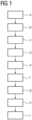
- FIG 1 shows schematically method steps a) to i) of a method according to an embodiment of the present invention, which serves to create a redundant automation system 1 for an automation system 2 to be controlled.
- a first step a information about the topology of a computer network 3 is provided.
- the computer network 3 is the Internet.
- the computer network 3 can also be a comparable computer network, such as a company intranet that connects a large number of company locations with one another via communication technology.
- the information provided in step a) is at least information about the structure or substructure of the computer network 3, which is formed by communication nodes 4 and communication paths 5 connecting them.
- the communication paths 5 can be wired and/or radio-based transmission routes.
- the information was obtained here based on static information, such as maps of the currently existing deep-sea cables and radio-based transmission routes. Information was also obtained by determining the network topology using network management protocols.
- step a additional information about the computer network 3 can be provided in step a), such as information about transmission speeds of individual communication paths 5, information collected from failure statistics about the probability of failure of communication nodes 4 and/or communication paths 5, etc.
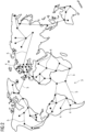
- FIG 2 shows an example of a network topology of the computer network 3 consisting of communication nodes 4 and communication paths 5, wherein a large number of communication nodes 4 and communication paths 5 are omitted for the sake of better clarity.
- step b information about the FIG 2
- the data centers 6 present in the network topology or connected to it are provided, including information about their locations. This is shown schematically in FIG 3 shown.
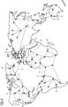
- step c If an automation system 1 is to be created for an automation system 2, the location of the automation system 2 within the network topology is identified in step c), see FIG 4 .
- step d at least one pair of data centers 6 is then identified which can be connected to the automation system 2 via communication paths 5 within the network topology and which have no overlaps and/or no common communication nodes.
- a total of 22 such pairs can be formed.
- Each of these pairs comprises an African data center 6 and a data center 6 located outside of Africa.
- step e) a pair of data centers 6 identified in step d) is then selected, including the associated communication paths 5. If, as is the case here, several pairs of data centers 6 were identified in step d), the selection in step e) can be made based on further criteria, such as the aforementioned transmission speeds of the individual communication paths 5, the probability of failure of communication nodes 4 and/or communication paths 5, etc.
- step b) additional information about the power supply and/or the current utilization and/or the computing power of the data centers 6 is also provided, which can be used in step e) to select an optimal pair. For example, in step e), it can be checked which pairs of data centers 6 have independent power supplies, with only pairs of data centers 6 with independent power supplies being shortlisted.
- the current utilization of the data centers 6 can be checked, with preference being given to pairs with data centers 6 with low utilization.
- a comparatively high computing power of both data centers 6 of a pair can also be decisive for the selection.
- Weighting factors can be assigned to the individual additional criteria in order to give them greater or lesser weight in the selection to be made in step e). to be given less weight.
- FIG 5 shows the final selection made in this example.
- control applications 7 set up to control the automation system 2 are then provided.
- the control applications 7 are set up in such a way that one of the control applications 7 works as a master and the other control application 7 works as a reserve, whereby in the event that the control application 7 working as a master fails, the control application 7 working as a reserve takes over its function as master.
- step g the control applications 7 are stored in the data centers 6 selected in step e).
- control applications 7 are then coupled in step h) via a synchronization path 8, which is preferably selected such that the synchronization path 8 and the two communication paths 5 connecting the control applications 7 to the automation system 2 have no overlaps and/or a minimal number of common communication nodes 4. If this is not possible, the communication paths 5 and the synchronization path 8 are selected such that they have as few overlaps and/or common nodes 4 as possible.
- step i) the control applications 7 are connected to the automation system 2 via the communication paths 5 selected in step e) and the data centers 6 via the selected synchronization path 8.
- the result is the FIG 6 shown arrangement or the one in FIG 7 automation system shown.
- a computer program comprising program code means which, when the program is executed on at least one computer, cause the at least one computer to carry out the steps of the method described above Only the identification of the plant location in step c) must be carried out by a user input.
- the automation system 1 is characterized by a very high level of availability despite the fact that its control applications 7 form part of a cloud computing structure. This availability can be further optimized by the type of synchronization mechanism with which the control applications 7 are synchronized and by the way in which the output data is handled in the redundant automation system 1.
- This context particular reference is made to the method described in the publication EP 2 657 797 B1 disclosed method for operating a redundant automation system 1, which can also be transferred to the redundant automation system 1 according to the invention.
Landscapes
- Engineering & Computer Science (AREA)
- Theoretical Computer Science (AREA)
- Physics & Mathematics (AREA)
- General Physics & Mathematics (AREA)
- General Engineering & Computer Science (AREA)
- Quality & Reliability (AREA)
- Automation & Control Theory (AREA)
- Computer Networks & Wireless Communication (AREA)
- Signal Processing (AREA)
- Manufacturing & Machinery (AREA)
- Computer Hardware Design (AREA)
- Hardware Redundancy (AREA)
Description
- Die vorliegende Offenbarung betrifft ein redundantes Automatisierungssystem umfassend zumindest eine zu steuernde, an einem Anlagenstandort aufgestellte Automatisierungsanlage mit zugehörigen Peripherieeinheiten sowie zwei über einen Synchronisationspfad kommunikationstechnisch miteinander gekoppelte, zur Steuerung der Automatisierungsanlage eingerichtete Steuerungsapplikationen, die mit der Automatisierungsanlage kommunikationstechnisch verbunden sind. Eine der Steuerungsapplikationen arbeitet als Master und die andere Steuerungsapplikation als Reserve, wobei für den Fall, dass die als Master arbeitende Steuerungsapplikation ausfällt, die als Reserve arbeitende Steuerungsapplikation deren Funktion als Master übernimmt. Ferner betrifft die vorliegende Erfindung ein Verfahren zur Erstellung eines solchen redundanten Automatisierungssystems. Darüber hinaus betrifft die Erfindung ein Computerprogramm sowie ein computerlesbares Medium zur Durchführung des Verfahrens.
- Im Automatisierungsumfeld werden verstärkt hochverfügbare Lösungen gefordert, die dazu geeignet sind, eventuell auftretende Stillstandszeiten einer Automatisierungsanlage auf ein Minimum zu reduzieren. Vor diesem Hintergrund wurden bereits redundante Automatisierungssysteme der eingangs genannten Art vorgeschlagen. Diese zeichnen sich dadurch aus, dass zwei sich untereinander synchronisierende Steuerungsapplikationen an die Peripherieeinheiten der Automatisierungsanlage angeschlossen sind, so dass die Funktion der als Master arbeitenden Steuerungsapplikation im Falle eines Ausfalls jederzeit von der als Reserve arbeitenden Steuerungsapplikation übernommen werden kann. Bezüglich der Häufigkeit der Synchronisation und deren Umfang können verschiedene Ausprägungen unterschieden werden, insbesondere der Warm-Standby und der Hot-Standby.
- In jüngster Vergangenheit wird zunehmend die Möglichkeit diskutiert, Steuerungsapplikationen in eine Cloud zu verlegen. Bei einer Cloud handelt es sich insbesondere um eine Infrastruktur, welche beispielsweise über das Internet verfügbar gemacht wird und welche in der Regel Speicherplatz, Rechenleistung und/oder Anwendungssoftware bereitstellt, ohne dass entsprechende Infrastrukturen auf einem lokalen Rechner installiert und gespeichert sein müssen. Bei einer Cloud wird die Hardware in der Regel nicht von dem Nutzer einer Anwendung bzw. Applikation selbst betrieben oder bereitgestellt. Unter einer Cloud bzw. Cloud-Computing kann insbesondere die Bereitstellung von IT-Infrastruktur als Dienstleistung ggf. von einem entfernten Standort aus zu verstehen sein. Eine Cloud kann über das Internet erreichbar sein, oder auch von einem Unternehmen als so genannte Private Cloud betrieben werden, bei welcher die IT-Infrastruktur über ein Netzwerk, z.B. ein Intranet des Unternehmens, erreichbar ist.
- Beim Verlegen von Steuerungsapplikationen in eine Cloud ist zu berücksichtigen, dass bei allen großen Cloud-Anbietern mit jährlichen Ausfallzeiten von mehreren Stunden zu rechnen ist. Die Betrachtung auf Monatsbasis zeigt sogar, dass mit einer MTTF (MTTF: Mean Time To Failure) von weniger als einem Monat gerechnet werden muss, wobei die Ausfälle mit einigen Minuten bis einigen Stunden Downtime einhergehen. So ergab beispielsweise die Analyse der Ausfälle verschiedener Cloud-Anbieter im März 2019 eine durchschnittliche Downtime von ca. 17 Minuten innerhalb des 30-Tage-Zeitraums, wobei die beiden Cloud-Anbieter mit der längsten Ausfallzeit unberücksichtigt blieben. Der Nutzer eines cloudbasierten Dienstes muss also davon ausgehen, dass seine Anwendung monatlich für einige Minuten nicht verfügbar ist. Bei einer Steuerungsapplikation führt dies unvermeidlich zu einem Stillstand der Automatisierungsanlage, der vom Anlagenbetreiber vermutlich nicht akzeptiert wird. In diesem Zusammenhang ist zu beachten, dass heutige speicherprogrammierbare Steuerungen eine typenabhängige mittlere Lebensdauer von 10 Jahren und mehr aufweisen.
- Im Ergebnis scheint die heute erreichbare Verfügbarkeit bzw. die erreichbare MTTF von Cloud-Diensten für die derzeitigen Anwendungen wie beispielsweise Webserver oder Datenbanken ausreichend zu sein. Für diese Anwendungen wird häufig versucht, die Verfügbarkeit durch Cold- oder Warm-Standby-Systeme zu erhöhen, die dann im Falle eines Ausfalls gestartet werden. Für Anwendungen in der Automatisierungstechnik wird die Verfügbarkeit indes als nicht ausreichend angesehen, da der Zustand der Steuerungsapplikationen und damit des Automatisierungsprozesses im Falle eines Ausfalls erhalten bleiben muss. Dies ist nur durch den Einsatz so genannter Hot-Standby-Systeme zu erreichen.
- Die
EP 3 547 618 A1 offenbart eine ausfallgesichterte Steuerungseinheit mit einem Primär- und einem Sekundärgerät, welch über eine erste Synchronisierungsverbindung miteinander verbunden sind. Über eine Vermittlungsfunktionseinheit kann das Primärgerät dem Sekundärgerät Daten für eine weitere zweite Synchronisationsverbindung unabhängig von der ersten bereitstellen. - Ausgehend von diesem Stand der Technik ist es eine Aufgabe der vorliegenden Erfindung, ein alternatives Verfahren zur Erstellung eines solchen zu schaffen.
- Das Verfahren ist für ein redundantes Automatisierungssystem gedacht, umfassend zumindest eine zu steuernde, an einem Anlagenstandort aufgestellte Automatisierungsanlage sowie zwei über einen Synchronisationspfad kommunikationstechnisch miteinander gekoppelte, zur Steuerung der Automatisierungsanlage eingerichtete, einen Teil einer Cloud-Computing-Struktur bildende Steuerungsapplikationen, deren Rechenressourcen an unterschiedlichen Standorten vorgesehen sind und die über das Internet oder über ein vergleichbares Rechnernetzwerk, das eine Vielzahl von Kommunikationsknotenpunkten und diese miteinander verbindende Kommunikationspfaden aufweist, mit der Automatisierungsanlage kommunikationstechnisch verbunden sind, wobei eine der Steuerungsapplikationen als Master und die andere Steuerungsapplikation als Reserve arbeitet, wobei für den Fall, dass die als Master arbeitende Steuerungsapplikation ausfällt, die als Reserve arbeitende Steuerungsapplikation deren Funktion als Master übernimmt, und wobei die Standorte der Rechenressourcen für die Steuerungsapplikationen derart gewählt sind, dass die Steuerungsapplikationen über zwei verschiedene, erfindungsgemäß keine gemeinsamen Kommunikationsknotenpunkten aufweisende Kommunikationspfade mit Automatisierungsanlage verbunden sind. Beispielweise werden also die Steuerungsapplikationen in eine Cloud verlegt. Zur Verbesserung der MTTF sind die Steuerungsapplikationen dabei über getrennte Kommunikationspfade des Internets bzw. des vergleichbaren Rechnernetzwerks kommunikationstechnisch an die Automatisierungsanlage bzw. an deren Peripherieeinheiten angebunden. Dabei ist sichergestellt, dass die Kommunikationspfade keine oder, sollte dies aufgrund des Anlagenstandorts und/oder der Standorte der Rechenressourcen für die Steuerungsapplikationen in Bezug auf die Topologie des Internets oder des vergleichbaren Rechnernetzwerkes nicht möglich sein, eine minimale Anzahl von gemeinsamen Kommunikationsknotenpunkten aufweisen. Dies ist dahingehend von Vorteil, dass, sollte der Kommunikationspfad zwischen der als Master arbeitenden Steuerungsapplikation und der Automatisierungsanlage ausfallen, die sichere Funktion des Kommunikationspfads zwischen der als Reserve arbeitenden Steuerungsapplikation und der Automatisierungsanlage gewährleistet ist und die als Reserve arbeitende Steuerungsapplikation die Funktion als Master übernehmen kann. Dies führt zu einer Verbesserung der MTTF der Steuerungsanwendungen auf einen für die Automatisierungstechnik nutzbaren Wert.
- Bei dem die Steuerungsapplikationen miteinander verbindenden Synchronisationspfad handelt es sich um einen Kommunikationspfad des Internet oder des vergleichbaren Rechnernetzwerks, wobei der Synchronisationspfad und die beiden die Steuerungsapplikationen mit der Automatisierungsanlage verbindenden Kommunikationspfade keine von gemeinsamen Kommunikationsknotenpunkten aufweisen. Dies führt ebenfalls zur Verbesserung der MTTF der Steuerungsanwendungen.
- Erfindungsgemäß handelt es sich bei den Rechenressourcen für die Steuerungsapplikationen um Rechenzentren, also um Gebäude bzw. Räumlichkeiten, in denen die zentrale Rechentechnik eines oder auch mehrerer Unternehmen untergebracht ist. Der Vorteil besteht darin, dass auf bereits bestehende Ressourcen zurückgegriffen wird.
- Vorteilhaft sind die Rechenressourcen für die Steuerungsapplikationen energieversorgungstechnisch voneinander entkoppelt. Handelt es sich bei den Rechenressourcen beispielsweise um verschiedene, energieversorgungstechnisch voneinander entkoppelte Rechenzentren, so ist die Verfügbarkeit des Automatisierungssystems auch dann gegeben, wenn die Energieversorgung eines Rechenzentrums ausfällt. Insbesondere werden die Standorte der Rechenressourcen für die Steuerungsapplikationen von vollständig voneinander entkoppelten Inselnetzen mit Energie versorgt. So können die Standorte beispielsweise derart gewählt sein, dass sie in unterschiedlichen Regionen oder Ländern angeordnet sind, deren Energieversorgung nicht miteinander gekoppelt ist.
- Die eingangs genannte Aufgabe wird durch ein Verfahren gemäß dem Anspruch 1 gelöst.
- In einem ersten Schritt a) werden Informationen über die Netzwerktopologie des Internets oder eines vergleichbaren Rechnernetzwerks gesammelt und bereitgestellt, also Informationen über die spezifische Anordnung der Geräte und Leitungen, die das Internet bzw. Rechnernetzwerk bilden, über das Computer untereinander verbunden sind und Daten austauschen, wobei unter dem Begriff "Leitungen" nicht nur kabelgebundene, sondern auch funkbasierte Übertragungsstrecken verstanden werden. Die Informationen können basierend auf statischen Informationen, wie beispielsweise Karten zu den derzeit vorhandenen Tiefseekabeln, und/oder durch Ermittlung der Netzwerktopologie mittels Netzwerkmanagement-Protokollen etc. gewonnen werden. In einem weiteren Schritt b) werden Informationen über innerhalb der Netzwerktopologie vorhandene Rechenzentren einschließlich Informationen über deren Standorte bereitgestellt. Im Schritt c) wird der Anlagestandort einer zu steuernden Automatisierungsanlage innerhalb der Netzwerktopologie identifiziert. Nach der Durchführung der Schritte a) bis c) liegen grundsätzlich sämtliche Informationen vor, die es benötigt, um die zu steuernde Automatisierungsanlage bzw. deren Peripherieeinheiten mit einem der Rechenzentren zu verbinden. In einem weiteren Schritt d) wird zumindest ein Paar von Rechenzentren identifiziert, die innerhalb der Netzwerktopologie über Kommunikationspfade mit der Automatisierungsanlage verbunden werden können und keine Überschneidungen und/oder keine gemeinsamen Kommunikationspunkte aufweisen · Es werden also diejenigen Rechenzentren identifiziert, die sich auf vollständig voneinander unabhängigen Kommunikationspfaden der bekannten Netzwerktopologie mit der Automatisierungsanlage verbinden lassen. In einem Schritt e) wird dann eines der in Schritt d) identifizierten Paare von Rechenzentren einschließlich der zugehörigen Kommunikationspfade ausgewählt. Entsprechend wird eine maximale MTTF für den Fall erzielt, dass einer der Kommunikationspfade zwischen dem Automatisierungssystem und einem der beiden Rechenzentren ausfallen sollte.
- Zusätzlich weist das Verfahren die weiteren Schritte auf: f) Bereitstellen von zwei zur Steuerung der Automatisierungsanlage eingerichteten Steuerungsapplikationen, wobei die Steuerungsapplikationen derart eingerichtet sind, dass eine der Steuerungsapplikationen als Master und die andere Steuerungsapplikation als Reserve arbeitet, und dass für den Fall, dass die als Master arbeitende Steuerungsapplikation ausfällt, die als Reserve arbeitende Steuerungsapplikation deren Funktion als Master übernimmt, g) Speichern der Steuerungsapplikationen in den in Schritt e) ausgewählten Rechenzentren; h) Koppeln der Steuerungsapplikationen über einen Synchronisationspfad; und i) Verbinden der Steuerungsapplikationen mit der Automatisierungsanlage über die in Schritt e) ausgewählten Kommunikationspfade.
- Dabei wird der in Schritt h) ausgewählte Synchronisationspfad bevorzugt derart gewählt, dass der Synchronisationspfad und die beiden die Steuerungsapplikationen mit der Automatisierungsanlage verbindenden Kommunikationspfade keine oder eine minimale Anzahl von gemeinsamen Kommunikationsknotenpunkten aufweisen.
- Erfindungsgemäß werden in Schritt b) Zusatzinformationen über die Stromversorgung und/oder über die aktuelle Auslastung und/oder über die Rechenleistung der Rechenzentren bereitgestellt, wobei die Auswahl in Schritt e) unter Berücksichtigung zumindest einer dieser Zusatzinformationen erfolgt. Wurden in Schritt d) beispielsweise mehrere potenzielle Paare von Rechenzentren ermittelt, mit denen die Automatisierungsanlage über verschiedene Kommunikationspfade verbunden werden könnte, so wird die Auswahl in Schritt e) basierend auf weiteren Kriterien getroffen. Beispielsweise kann geprüft werden, welche Paare von Rechenzentren unabhängige Stromversorgungen aufweisen, so dass nur Paare von Rechenzentren mit unabhängiger Stromversorgung in die engere Auswahl kommen. Alternativ oder zusätzlich kann die aktuelle Auslastung der Rechenzentren der in Schritt d) identifizierten Paare geprüft werden. Entsprechend würden bei der Auswahl in Schritt e) diejenigen Paare bevorzugt werden, deren Rechenzentren eine geringe Auslastung aufweisen. Alternativ oder zusätzlich kann auch die Rechenleistung der entsprechenden Rechenzentren als Auswahlkriterium in Schritt e) herangezogen werden, wobei Rechenzentren mit hoher Rechenleistung der Vorrang gewährt wird. Fließen mehrere zusätzliche Kriterien in die Auswahl in Schritt e) ein, so können den einzelnen Kriterien Prioritäten oder Wichtigkeitskennzahlen zugewiesen werden.
- Ein weiterer Gegenstand der vorliegenden Erfindung ist ein Computerprogramm umfassend Programmcode-Mittel, die bei der Ausführung des Programms auf wenigstens einem Computer, den wenigstens einen Computer veranlassen, die Schritte des erfindungsgemäßen Verfahrens durchzuführen.
- Darüber hinaus betrifft die Erfindung ein computerlesbares Medium, das Instruktionen umfasst, die, wenn sie auf wenigstens einem Computer ausgeführt werden, den wenigstens einen Computer veranlassen, die Schritte des erfindungsgemäßen Verfahrens durchzuführen.
- Bei dem computerlesbaren Medium kann es sich beispielsweise um eine CD-ROM oder DVD oder einen USB- oder Flashspeicher handeln. Es sei angemerkt, dass unter einem computerlesbaren Medium nicht ausschließlich ein körperliches Medium zu verstehen sein soll, sondern ein solches beispielswiese auch in Form eines Datenstromes und/oder eines Signals, welches einen Datenstrom repräsentiert, vorliegen kann.
- Weitere Merkmale und Vorteile der vorliegenden Erfindung werden anhand der nachfolgenden Beschreibung unter Bezugnahme auf die beiliegende Zeichnung deutlich. Dabei zeigt
- FIG 1
- ein Ablaufdiagramm, das schematisch die Verfahrensschritte eines Verfahrens gemäß einer Ausführungsform der vorliegenden Erfindung;
- FIG 2
- eine schematische Ansicht einer Topologie eines Netzwerkes;
- FIG 3
- eine Ansicht gemäß
FIG 2 mit ergänzten Datenzentren; - FIG 4
- eine Ansicht gemäß
FIG 3 mit ergänzter Automatisierungsanlage; - FIG 5
- eine Ansicht gemäß
FIG 4 mit ergänzten Kommunikationspfaden zwischen der Automatisierungsanlage und ausgewählten Rechenzentren; - FIG 6
- eine Ansicht gemäß
FIG 5 mit ergänztem ausgewählten Synchronisierungspfad zwischen den ausgewählten Rechenzentren und - FIG 7
- eine schematische Ansicht eines Automatisierungssystems gemäß einer Ausführungsform der vorliegenden Erfindung, das unter Durchführung des in
FIG 1 dargestellten Verfahrens erstellt wurde. - Die
FIG 1 zeigt schematisch Verfahrensschritte a) bis i) eines Verfahrens gemäß einer Ausführungsform der vorliegenden Erfindung, das dazu dient, ein redundantes Automatisierungssystem 1 für eine zu steuernde Automatisierungsanlage 2 zu erstellen. - In einem ersten Schritt a) werden Informationen über die Topologie eines Rechnernetzwerks 3 bereitgestellt. Vorliegend handelt es sich bei dem Rechnernetzwerk 3 um das Internet.
- Alternativ kann das Rechnernetzwerk 3 aber auch ein vergleichbares Rechnernetzwerk sein, wie beispielsweise um ein Intranet eines Unternehmens, das eine Vielzahl von Unternehmensstandorten kommunikationstechnisch miteinander verbindet. Bei den in Schritt a) bereitgestellten Informationen handelt es sich zumindest um Informationen über die Struktur oder Teilstruktur des Rechnernetzwerks 3, die durch Kommunikationsknotenpunkte 4 und diese miteinander verbindende Kommunikationspfade 5 gebildet wird. Bei den Kommunikationspfaden 5 kann es sich um kabelgebundene und/oder funkbasierte Übertragungsstrecken handeln. Die Informationen wurden vorliegend basierend auf statischen Informationen gewonnen, wie beispielsweise Karten zu den derzeit vorhandenen Tiefseekabeln und funkbasierten Übertragungsstrecken. Ferner wurden Informationen auch durch Ermittlung der Netzwerktopologie mittels Netzwerkmanagement-Protokollen gewonnen. Zudem können in Schritt a) ergänzende Informationen über das Rechnernetzwerk 3 bereitgestellt werden, wie beispielsweise Informationen über Übertragungsgeschwindigkeiten einzelner Kommunikationspfade 5, anhand von Ausfallstatistiken gesammelte Informationen über die Ausfallwahrscheinlichkeit von Kommunikationsknotenpunkten 4 und/oder Kommunikationspfaden 5, etc.
FIG 2 zeigt exemplarisch eine Netzwerktopologie des Rechnernetzwerks 3 bestehend aus Kommunikationsknotenpunkten 4 und Kommunikationspfaden 5, wobei eine Vielzahl von Kommunikationsknotenpunkten 4 und Kommunikationspfaden 5 der besseren Übersichtlichkeit halber weggelassen sind. - In einem weiteren Schritt b) werden Informationen über innerhalb der in
FIG 2 dargestellten Netzwerktopologie vorhandene bzw. an diese angebundene Rechenzentren 6 einschließlich Informationen über deren Standorte bereitgestellt. Dies ist schematisch inFIG 3 dargestellt. - Soll nun für eine Automatisierungsanlage 2 ein Automatisierungssystem 1 erstellt werden, so wird in Schritt c) der Anlagenstandort der Automatisierungsanlage 2 innerhalb der Netzwerktopologie identifiziert, siehe
FIG 4 . - In einem sich anschließenden Schritt d) wird dann zumindest ein Paar von Rechenzentren 6 identifiziert, die innerhalb der Netzwerktopologie über Kommunikationspfade 5 mit der Automatisierungsanlage 2 verbunden werden können und keine Überschneidungen und/oder keine gemeinsamen Kommunikationsknotenpunkte aufweisen.
- Im dargestellten Beispiel können insgesamt 22 solcher Paare gebildet werden. Jedes dieser Paare umfasst ein afrikanisches Rechenzentrum 6 und ein Rechenzentrum 6, das außerhalb von Afrika angeordnet ist.
- In einem weiteren Schritt e) wird dann ein in Schritt d) identifiziertes Paar von Rechenzentren 6 einschließlich der zugehörigen Kommunikationspfade 5 ausgewählt. Wurden in Schritt d), wie vorliegend der Fall, mehrere Paare von Rechenzentren 6 identifiziert, so kann die Auswahl in Schritt e) anhand weiterer Kriterien erfolgen, wie beispielsweise anhand der zuvor genannten Übertragungsgeschwindigkeiten der einzelnen Kommunikationspfade 5, der Ausfallwahrscheinlichkeit von Kommunikationsknotenpunkten 4 und/oder Kommunikationspfaden 5, etc. Erfindungsgemäß werden in Schritt b) ferner Zusatzinformationen über die Stromversorgung und/oder über die aktuelle Auslastung und/oder über die Rechenleistung der Rechenzentren 6 bereitgestellt, die in Schritt e) zur Auswahl eines optimalen Paars herangezogen werden können. So kann in Schritt e) beispielsweise geprüft werden, welche Paare von Rechenzentren 6 voneinander unabhängige Stromversorgungen aufweisen, wobei dann nur Paare von Rechenzentren 6 mit voneinander unabhängiger Stromversorgung in die engere Auswahl kommen. Alternativ oder zusätzlich kann die aktuelle Auslastung der Rechenzentren 6 geprüft werden, wobei Paare mit gering ausgelasteten Rechenzentren 6 bevorzugt werden. Alternativ oder zusätzlich kann auch eine vergleichsweise hohe Rechenleistung beider Rechenzentren 6 eines Paares ausschlaggebend für die Auswahl sein. Den einzelnen zusätzlichen Kriterien können Gewichtungsfaktoren zugeordnet werden, um diese bei der in Schritt e) zu treffenden Auswahl stärker oder schwächer zu gewichten.
FIG 5 zeigt die im vorliegenden Beispiel letztendlich getroffene Auswahl. - In einem Schritt f) werden dann zwei zur Steuerung der Automatisierungsanlage 2 eingerichtete Steuerungsapplikationen 7 bereitgestellt. Die Steuerungsapplikationen 7 sind derart eingerichtet, dass eine der Steuerungsapplikationen 7 als Master und die andere Steuerungsapplikation 7 als Reserve arbeitet, wobei für den Fall, dass die als Master arbeitende Steuerungsapplikation 7 ausfällt, die als Reserve arbeitende Steuerungsapplikation 7 deren Funktion als Master übernimmt.
- Im Schritt g) werden die Steuerungsapplikationen 7 in den in Schritt e) ausgewählten Rechenzentren 6 gespeichert.
- Daraufhin werden die Steuerungsapplikationen 7 in Schritt h) über einen Synchronisationspfad 8 gekoppelt, der bevorzugt derart gewählt wird, dass der Synchronisationspfad 8 und die beiden die Steuerungsapplikationen 7 mit der Automatisierungsanlage 2 verbindenden Kommunikationspfade 5 keine Überschneidungen und/oder eine minimale Anzahl von gemeinsamen Kommunikationsknotenpunkten 4 aufweisen. Ist dies nicht möglich, so werden die Kommunikationspfade 5 und der Synchronisationspfad 8 derart gewählt, dass diese möglichst wenige Überschneidungen und/oder gemeinsame Knotenpunkte 4 aufweisen.
- In Schritt i) werden die Steuerungsapplikationen 7 mit der Automatisierungsanlage 2 über die in Schritt e) ausgewählten Kommunikationspfade 5 und die Rechenzentren 6 über den ausgewählten Synchronisationspfad 8 verbunden. Im Ergebnis gibt sich die in
FIG 6 dargestellte Anordnung bzw. das inFIG 7 dargestellte Automatisierungssystem. - Vorliegend ist ein Computerprogramm umfassend Programmcode-Mittel vorgesehen, die bei der Ausführung des Programms auf wenigstens einen Computer den wenigstens einen Computer veranlassen, die Schritte des zuvor beschriebenen Verfahrens durchzuführen. Lediglich die Identifikation des Anlagenstandorts in Schritt c) muss durch Eingabe eines Benutzers erfolgen.
- Das erfindungsgemäße Automatisierungssystem 1 zeichnet sich trotz der Tatsache, dass seine Steuerungsapplikationen 7 einen Teil einer Cloud-Computing-Struktur bilden, durch eine sehr hohe Verfügbarkeit aus. Diese Verfügbarkeit kann durch die Art des Synchronisationsmechanismus, mit dem die Steuerungsapplikationen 7 synchronisiert werden, und durch die Art und Weise, wie die Ausgangsdaten in dem redundanten Automatisierungssystem 1 gehandhabt werden, weiter optimiert werden. In diesem Zusammenhang wird insbesondere auf das in der Druckschrift
EP 2 657 797 B1 offenbarte Verfahren zum Betreiben eines redundanten Automatisierungssystems 1 Bezug genommen, das sich auch auf das erfindungsgemäße redundante Automatisierungssystem 1 übertragen lässt.
Claims (3)
- Verfahren zur Erstellung eines redundanten Automatisierungssystems (1), wobei das Verfahren die Schritte aufweist:a) Bereitstellen von Informationen über eine Netzwerktopologie eines Rechnernetzwerks einschließlich Informationen über die Struktur oder Teilstruktur des Rechnernetzwerks, die durch Kommunikationsknotenpunkten (4) und über diese miteinander verbindende Kommunikationspfade (5) gebildet wird;b) Bereitstellen von Informationen über innerhalb der Netzwerktopologie vorhandene Rechenzentren (6) einschließlich Informationen über deren Standorte;c) Identifikation des Anlagenstandorts einer zu steuernden Automatisierungsanlage (2) innerhalb der Netzwerktopologie;d) Identifikation zumindest eines Paars von Rechenzentren (6), die sich innerhalb der Netzwerktopologie auf vollständig voneinander unabhängigen Kommunikationspfaden der bekannten Netzwerktopologie mit der Automatisierungsanlage verbinden lassen;e) Auswahl eines in Schritt d) identifizierten Paars von Rechenzentren (6) einschließlich der zugehörigen Kommunikationspfade (5);f) Bereitstellen von zwei zur Steuerung der Automatisierungsanlage (2) eingerichteten Steuerungsapplikationen (7), wobei die Steuerungsapplikationen (7) derart eingerichtet sind, dass eine der Steuerungsapplikationen (7) als Master und die andere Steuerungsapplikation (7) als Reserve arbeitet, und dass für den Fall, dass die als Master arbeitende Steuerungsapplikation (7) ausfällt, die als Reserve arbeitende Steuerungsapplikation (7) deren Funktion als Master übernimmt;g) Speichern der Steuerungsapplikationen (7) in den in Schritt e) ausgewählten Rechenzentren (6);h) Koppeln der Steuerungsapplikationen (7) über einen Synchronisationspfad (8); undi) Verbinden der Steuerungsapplikationen (7) mit der Automatisierungsanlage (2) über die in Schritt e) ausgewählten Kommunikationspfade (5), wobei der Synchronisationspfad (8) derart gewählt wird, dass der Synchronisationspfad (8) und die beiden die Steuerungsapplikationen (7) mit der Automatisierungsanlage (2) verbindenden Kommunikationspfade (5) keine gemeinsamen Kommunikationsknotenpunkte (4) aufweisen, dadurch gekennzeichnet, dass in Schritt b) Zusatzinformationen über die Stromversorgung und/oder über die aktuelle Auslastung und/oder über die Rechenleistung der Rechenzentren (6) bereitgestellt werden, und dass die Auswahl in Schritt e) unter Berücksichtigung zumindest einer dieser Zusatzinformationen erfolgt.
- Computerprogramm umfassend Programmcode-Mittel, die bei der Ausführung des Programms auf wenigstens einem Computer den wenigstens einen Computer veranlassen, die Schritte des Verfahrens nach Anspruch 1 durchzuführen.
- Computerlesbares Medium, das Instruktionen umfasst, die, wenn sie auf wenigstens einem Computer ausgeführt werden, den wenigstens einen Computer veranlassen, die Schritte des Verfahrens nach Anspruch 1 durchzuführen.
Priority Applications (3)
| Application Number | Priority Date | Filing Date | Title |
|---|---|---|---|
| EP19201463.7A EP3800517B1 (de) | 2019-10-04 | 2019-10-04 | Verfahren zur erstellung eines redundanten automatisierungssystems, computerprogramm und computerlesbares medium |
| CN202011068904.XA CN112612201B (zh) | 2019-10-04 | 2020-09-30 | 自动化系统、创建自动化系统的方法和计算机可读介质 |
| US17/061,707 US11550270B2 (en) | 2019-10-04 | 2020-10-02 | Redundant automation system, method for creating the automation system, computer program and computer readable medium |
Applications Claiming Priority (1)
| Application Number | Priority Date | Filing Date | Title |
|---|---|---|---|
| EP19201463.7A EP3800517B1 (de) | 2019-10-04 | 2019-10-04 | Verfahren zur erstellung eines redundanten automatisierungssystems, computerprogramm und computerlesbares medium |
Publications (3)
| Publication Number | Publication Date |
|---|---|
| EP3800517A1 EP3800517A1 (de) | 2021-04-07 |
| EP3800517B1 true EP3800517B1 (de) | 2024-08-14 |
| EP3800517C0 EP3800517C0 (de) | 2024-08-14 |
Family
ID=68165473
Family Applications (1)
| Application Number | Title | Priority Date | Filing Date |
|---|---|---|---|
| EP19201463.7A Active EP3800517B1 (de) | 2019-10-04 | 2019-10-04 | Verfahren zur erstellung eines redundanten automatisierungssystems, computerprogramm und computerlesbares medium |
Country Status (3)
| Country | Link |
|---|---|
| US (1) | US11550270B2 (de) |
| EP (1) | EP3800517B1 (de) |
| CN (1) | CN112612201B (de) |
Families Citing this family (2)
| Publication number | Priority date | Publication date | Assignee | Title |
|---|---|---|---|---|
| EP4068014B1 (de) * | 2021-03-30 | 2023-11-08 | Siemens Aktiengesellschaft | Hochverfügbare cloud-basierte automatisierungslösung mit optimierten übertragungszeiten |
| US12500951B1 (en) * | 2024-05-29 | 2025-12-16 | Bank Of America Corporation | System and method for automated synchronization of data |
Family Cites Families (10)
| Publication number | Priority date | Publication date | Assignee | Title |
|---|---|---|---|---|
| EP2418580B1 (de) * | 2010-08-10 | 2012-10-10 | Siemens Aktiengesellschaft | Verfahren zum Betreiben eines Netzwerkes und Netzwerk |
| CN102111299A (zh) * | 2011-03-07 | 2011-06-29 | 中控科技集团有限公司 | 冗余网络系统及其冗余实现方法 |
| EP2657797B1 (de) * | 2012-04-27 | 2017-01-18 | Siemens Aktiengesellschaft | Verfahren zum Betreiben eines redundanten Automatisierungssystems |
| JP5748363B2 (ja) * | 2013-02-01 | 2015-07-15 | 日本電信電話株式会社 | 通信経路設計装置、通信経路設計方法及び通信経路設計プログラム |
| DE102013106954A1 (de) * | 2013-07-02 | 2015-01-08 | Phoenix Contact Gmbh & Co. Kg | Verfahren zur Fehlerüberwachung, Steuer- und Datenübertragungsanlage und Steuereinrichtung |
| US11513477B2 (en) * | 2015-03-16 | 2022-11-29 | Rockwell Automation Technologies, Inc. | Cloud-based industrial controller |
| US10003522B2 (en) * | 2015-08-27 | 2018-06-19 | Facebook, Inc. | Routing with flow over shared risk link groups |
| KR20190007469A (ko) * | 2016-05-12 | 2019-01-22 | 달리 시스템즈 씨오. 엘티디. | 공공 안전 분산형 안테나 시스템에서의 리던던시 |
| US20190199626A1 (en) * | 2017-12-26 | 2019-06-27 | Cisco Technology, Inc. | Routing traffic across isolation networks |
| EP3547618B1 (de) * | 2018-03-29 | 2023-03-01 | Siemens Aktiengesellschaft | Verfahren zum aufbau einer redundanten kommunikationsverbindung und ausfallgesicherte steuerungseinheit |
-
2019
- 2019-10-04 EP EP19201463.7A patent/EP3800517B1/de active Active
-
2020
- 2020-09-30 CN CN202011068904.XA patent/CN112612201B/zh active Active
- 2020-10-02 US US17/061,707 patent/US11550270B2/en active Active
Non-Patent Citations (2)
| Title |
|---|
| ANONYMOUS: "IP address - Wikipedia", WIKIPEDIA, 7 October 2019 (2019-10-07), pages 1 - 11, XP093003969, Retrieved from the Internet <URL:https://en.wikipedia.org/w/index.php?title=IP_address&oldid=920139052> [retrieved on 20221201] * |
| ANONYMOUS: "IP routing - Wikipedia", WIKIPEDIA, 7 October 2019 (2019-10-07), pages 1 - 3, XP093003854, Retrieved from the Internet <URL:https://en.wikipedia.org/w/index.php?title=IP_routing&oldid=920081455> [retrieved on 20221201] * |
Also Published As
| Publication number | Publication date |
|---|---|
| CN112612201A (zh) | 2021-04-06 |
| CN112612201B (zh) | 2024-06-21 |
| EP3800517A1 (de) | 2021-04-07 |
| US20210103254A1 (en) | 2021-04-08 |
| EP3800517C0 (de) | 2024-08-14 |
| US11550270B2 (en) | 2023-01-10 |
Similar Documents
| Publication | Publication Date | Title |
|---|---|---|
| DE2908316C2 (de) | Modular aufgebaute Multiprozessor-Datenverarbeitungsanlage | |
| DE69801418T2 (de) | Datenaufteilung und -dupliziering in einem verteilten datenverarbeitungssystem | |
| DE60318468T2 (de) | Verfahren zur lösung von entscheidungslosigkeiten in einem cluster-rechnersystem | |
| EP2667269B1 (de) | Verfahren zum Betreiben eines redundanten Automatisierungssystems | |
| DE3751230T2 (de) | Selbstgleichsetzung in redundanten Kanälen. | |
| DE102012000158B4 (de) | Adaptives mehrfach redundantes ringförmiges Netzwerk und Verfahren zum Wählen einer Umleitung | |
| DE102012003242A1 (de) | Verfahren zum ausfallsicheren Betreiben eines Prozesssteuersystems mit redundanten Steuereinrichtungen | |
| EP3017570B1 (de) | Steuerungsvorrichtung, netzwerkknoten und verfahren zum austausch von daten über ein datennetz | |
| DE4305522A1 (de) | Einrichtung zur automatischen Erzeugung einer Wissensbasis für ein Diagnose-Expertensystem | |
| DE102016219854A1 (de) | Computersystem und Verfahren zum dynamischen Anpassen eines software-definierten Netzwerks | |
| DE19780639C2 (de) | Arbeitsübernahmesystem | |
| WO2002065289A1 (de) | Automatische inbetriebnahme eines clustersystems nach einem heilbaren fehler | |
| WO2005073852A1 (de) | Verfahren zum betreiben einer anordnung mehrerer rechner bei einem rechnerausfall | |
| EP2732347A1 (de) | Verfahren und system zur dynamischen verteilung von programmfunktionen in verteilten steuerungssystemen | |
| EP3800517A1 (de) | Redundantes automatisierungssystem, verfahren zur erstellung eines solchen automatisierungssystems, computerprogramm und computerlesbares medium | |
| DE102020200453A1 (de) | Multi-Cloud-Industriecontroller | |
| EP2418580B1 (de) | Verfahren zum Betreiben eines Netzwerkes und Netzwerk | |
| EP4335127B1 (de) | Computer-implementiertes verfahren zum betrieb eines end-geräts mit hoher verfügbarkeit in einem netzwerk | |
| EP1820307B1 (de) | Verfahren zum nachweis der verf]gbarkeit von systemkomponenten eines redundanten kommunikationssystems | |
| EP1743224A1 (de) | Anordnung und verfahren zum betreiben einer technischen anlage | |
| EP2021922B1 (de) | Verfahren und vorrichtung für ein fehlertoleranzmanagement einer softwarekomponente | |
| WO2016079091A1 (de) | Verfahren zum betreiben eines ersten und zumindest eines zweiten feldgerätes | |
| DE10049621A1 (de) | Verfahren zum Betreiben eines Datenverarbeitungssystem | |
| DE10025283B4 (de) | Vorrichtung zur dynamischen Verbindung von mindestens zwei Datenringzellen | |
| LU101163B1 (de) | Verfahren und Vorrichtungen für eine Lastzuweisung und Überwachung für eine zuzuweisende versorgungssicherheitskritische Ressource in einem Netzwerk |
Legal Events
| Date | Code | Title | Description |
|---|---|---|---|
| PUAI | Public reference made under article 153(3) epc to a published international application that has entered the european phase |
Free format text: ORIGINAL CODE: 0009012 |
|
| STAA | Information on the status of an ep patent application or granted ep patent |
Free format text: STATUS: THE APPLICATION HAS BEEN PUBLISHED |
|
| AK | Designated contracting states |
Kind code of ref document: A1 Designated state(s): AL AT BE BG CH CY CZ DE DK EE ES FI FR GB GR HR HU IE IS IT LI LT LU LV MC MK MT NL NO PL PT RO RS SE SI SK SM TR |
|
| AX | Request for extension of the european patent |
Extension state: BA ME |
|
| STAA | Information on the status of an ep patent application or granted ep patent |
Free format text: STATUS: REQUEST FOR EXAMINATION WAS MADE |
|
| 17P | Request for examination filed |
Effective date: 20211006 |
|
| RBV | Designated contracting states (corrected) |
Designated state(s): AL AT BE BG CH CY CZ DE DK EE ES FI FR GB GR HR HU IE IS IT LI LT LU LV MC MK MT NL NO PL PT RO RS SE SI SK SM TR |
|
| STAA | Information on the status of an ep patent application or granted ep patent |
Free format text: STATUS: EXAMINATION IS IN PROGRESS |
|
| 17Q | First examination report despatched |
Effective date: 20221207 |
|
| GRAP | Despatch of communication of intention to grant a patent |
Free format text: ORIGINAL CODE: EPIDOSNIGR1 |
|
| STAA | Information on the status of an ep patent application or granted ep patent |
Free format text: STATUS: GRANT OF PATENT IS INTENDED |
|
| RIC1 | Information provided on ipc code assigned before grant |
Ipc: G06F 11/20 20060101ALI20240321BHEP Ipc: G05B 19/418 20060101ALI20240321BHEP Ipc: G05B 9/03 20060101AFI20240321BHEP |
|
| INTG | Intention to grant announced |
Effective date: 20240419 |
|
| GRAS | Grant fee paid |
Free format text: ORIGINAL CODE: EPIDOSNIGR3 |
|
| GRAA | (expected) grant |
Free format text: ORIGINAL CODE: 0009210 |
|
| STAA | Information on the status of an ep patent application or granted ep patent |
Free format text: STATUS: THE PATENT HAS BEEN GRANTED |
|
| AK | Designated contracting states |
Kind code of ref document: B1 Designated state(s): AL AT BE BG CH CY CZ DE DK EE ES FI FR GB GR HR HU IE IS IT LI LT LU LV MC MK MT NL NO PL PT RO RS SE SI SK SM TR |
|
| REG | Reference to a national code |
Ref country code: GB Ref legal event code: FG4D Free format text: NOT ENGLISH |
|
| REG | Reference to a national code |
Ref country code: CH Ref legal event code: EP |
|
| REG | Reference to a national code |
Ref country code: DE Ref legal event code: R096 Ref document number: 502019011876 Country of ref document: DE |
|
| REG | Reference to a national code |
Ref country code: IE Ref legal event code: FG4D Free format text: LANGUAGE OF EP DOCUMENT: GERMAN |
|
| U01 | Request for unitary effect filed |
Effective date: 20240814 |
|
| U07 | Unitary effect registered |
Designated state(s): AT BE BG DE DK EE FI FR IT LT LU LV MT NL PT RO SE SI Effective date: 20240902 |
|
| U20 | Renewal fee for the european patent with unitary effect paid |
Year of fee payment: 6 Effective date: 20241018 |
|
| PG25 | Lapsed in a contracting state [announced via postgrant information from national office to epo] |
Ref country code: NO Free format text: LAPSE BECAUSE OF FAILURE TO SUBMIT A TRANSLATION OF THE DESCRIPTION OR TO PAY THE FEE WITHIN THE PRESCRIBED TIME-LIMIT Effective date: 20241114 |
|
| PG25 | Lapsed in a contracting state [announced via postgrant information from national office to epo] |
Ref country code: GR Free format text: LAPSE BECAUSE OF FAILURE TO SUBMIT A TRANSLATION OF THE DESCRIPTION OR TO PAY THE FEE WITHIN THE PRESCRIBED TIME-LIMIT Effective date: 20241115 Ref country code: PL Free format text: LAPSE BECAUSE OF FAILURE TO SUBMIT A TRANSLATION OF THE DESCRIPTION OR TO PAY THE FEE WITHIN THE PRESCRIBED TIME-LIMIT Effective date: 20240814 |
|
| PG25 | Lapsed in a contracting state [announced via postgrant information from national office to epo] |
Ref country code: IS Free format text: LAPSE BECAUSE OF FAILURE TO SUBMIT A TRANSLATION OF THE DESCRIPTION OR TO PAY THE FEE WITHIN THE PRESCRIBED TIME-LIMIT Effective date: 20241214 |
|
| PG25 | Lapsed in a contracting state [announced via postgrant information from national office to epo] |
Ref country code: HR Free format text: LAPSE BECAUSE OF FAILURE TO SUBMIT A TRANSLATION OF THE DESCRIPTION OR TO PAY THE FEE WITHIN THE PRESCRIBED TIME-LIMIT Effective date: 20240814 |
|
| PG25 | Lapsed in a contracting state [announced via postgrant information from national office to epo] |
Ref country code: RS Free format text: LAPSE BECAUSE OF FAILURE TO SUBMIT A TRANSLATION OF THE DESCRIPTION OR TO PAY THE FEE WITHIN THE PRESCRIBED TIME-LIMIT Effective date: 20241114 Ref country code: ES Free format text: LAPSE BECAUSE OF FAILURE TO SUBMIT A TRANSLATION OF THE DESCRIPTION OR TO PAY THE FEE WITHIN THE PRESCRIBED TIME-LIMIT Effective date: 20240814 |
|
| PG25 | Lapsed in a contracting state [announced via postgrant information from national office to epo] |
Ref country code: RS Free format text: LAPSE BECAUSE OF FAILURE TO SUBMIT A TRANSLATION OF THE DESCRIPTION OR TO PAY THE FEE WITHIN THE PRESCRIBED TIME-LIMIT Effective date: 20241114 Ref country code: PL Free format text: LAPSE BECAUSE OF FAILURE TO SUBMIT A TRANSLATION OF THE DESCRIPTION OR TO PAY THE FEE WITHIN THE PRESCRIBED TIME-LIMIT Effective date: 20240814 Ref country code: NO Free format text: LAPSE BECAUSE OF FAILURE TO SUBMIT A TRANSLATION OF THE DESCRIPTION OR TO PAY THE FEE WITHIN THE PRESCRIBED TIME-LIMIT Effective date: 20241114 Ref country code: IS Free format text: LAPSE BECAUSE OF FAILURE TO SUBMIT A TRANSLATION OF THE DESCRIPTION OR TO PAY THE FEE WITHIN THE PRESCRIBED TIME-LIMIT Effective date: 20241214 Ref country code: HR Free format text: LAPSE BECAUSE OF FAILURE TO SUBMIT A TRANSLATION OF THE DESCRIPTION OR TO PAY THE FEE WITHIN THE PRESCRIBED TIME-LIMIT Effective date: 20240814 Ref country code: GR Free format text: LAPSE BECAUSE OF FAILURE TO SUBMIT A TRANSLATION OF THE DESCRIPTION OR TO PAY THE FEE WITHIN THE PRESCRIBED TIME-LIMIT Effective date: 20241115 Ref country code: ES Free format text: LAPSE BECAUSE OF FAILURE TO SUBMIT A TRANSLATION OF THE DESCRIPTION OR TO PAY THE FEE WITHIN THE PRESCRIBED TIME-LIMIT Effective date: 20240814 |
|
| PG25 | Lapsed in a contracting state [announced via postgrant information from national office to epo] |
Ref country code: SM Free format text: LAPSE BECAUSE OF FAILURE TO SUBMIT A TRANSLATION OF THE DESCRIPTION OR TO PAY THE FEE WITHIN THE PRESCRIBED TIME-LIMIT Effective date: 20240814 |
|
| PG25 | Lapsed in a contracting state [announced via postgrant information from national office to epo] |
Ref country code: CZ Free format text: LAPSE BECAUSE OF FAILURE TO SUBMIT A TRANSLATION OF THE DESCRIPTION OR TO PAY THE FEE WITHIN THE PRESCRIBED TIME-LIMIT Effective date: 20240814 |
|
| PG25 | Lapsed in a contracting state [announced via postgrant information from national office to epo] |
Ref country code: SK Free format text: LAPSE BECAUSE OF FAILURE TO SUBMIT A TRANSLATION OF THE DESCRIPTION OR TO PAY THE FEE WITHIN THE PRESCRIBED TIME-LIMIT Effective date: 20240814 |
|
| REG | Reference to a national code |
Ref country code: CH Ref legal event code: PL |
|
| PLBE | No opposition filed within time limit |
Free format text: ORIGINAL CODE: 0009261 |
|
| STAA | Information on the status of an ep patent application or granted ep patent |
Free format text: STATUS: NO OPPOSITION FILED WITHIN TIME LIMIT |
|
| PG25 | Lapsed in a contracting state [announced via postgrant information from national office to epo] |
Ref country code: MC Free format text: LAPSE BECAUSE OF FAILURE TO SUBMIT A TRANSLATION OF THE DESCRIPTION OR TO PAY THE FEE WITHIN THE PRESCRIBED TIME-LIMIT Effective date: 20240814 |
|
| 26N | No opposition filed |
Effective date: 20250515 |
|
| GBPC | Gb: european patent ceased through non-payment of renewal fee |
Effective date: 20241114 |
|
| PG25 | Lapsed in a contracting state [announced via postgrant information from national office to epo] |
Ref country code: CH Free format text: LAPSE BECAUSE OF NON-PAYMENT OF DUE FEES Effective date: 20241031 |
|
| PG25 | Lapsed in a contracting state [announced via postgrant information from national office to epo] |
Ref country code: GB Free format text: LAPSE BECAUSE OF NON-PAYMENT OF DUE FEES Effective date: 20241114 |
|
| PG25 | Lapsed in a contracting state [announced via postgrant information from national office to epo] |
Ref country code: IE Free format text: LAPSE BECAUSE OF NON-PAYMENT OF DUE FEES Effective date: 20241004 |
|
| U20 | Renewal fee for the european patent with unitary effect paid |
Year of fee payment: 7 Effective date: 20251020 |
|
| PG25 | Lapsed in a contracting state [announced via postgrant information from national office to epo] |
Ref country code: CY Free format text: LAPSE BECAUSE OF FAILURE TO SUBMIT A TRANSLATION OF THE DESCRIPTION OR TO PAY THE FEE WITHIN THE PRESCRIBED TIME-LIMIT; INVALID AB INITIO Effective date: 20191004 |
|
| PG25 | Lapsed in a contracting state [announced via postgrant information from national office to epo] |
Ref country code: HU Free format text: LAPSE BECAUSE OF FAILURE TO SUBMIT A TRANSLATION OF THE DESCRIPTION OR TO PAY THE FEE WITHIN THE PRESCRIBED TIME-LIMIT; INVALID AB INITIO Effective date: 20191004 |
|
| PG25 | Lapsed in a contracting state [announced via postgrant information from national office to epo] |
Ref country code: TR Free format text: LAPSE BECAUSE OF FAILURE TO SUBMIT A TRANSLATION OF THE DESCRIPTION OR TO PAY THE FEE WITHIN THE PRESCRIBED TIME-LIMIT Effective date: 20240814 |