EP3547767A1 - Verfahren und vorrichtung zum senden von synchronisationssignalen - Google Patents
Verfahren und vorrichtung zum senden von synchronisationssignalen Download PDFInfo
- Publication number
- EP3547767A1 EP3547767A1 EP17885213.3A EP17885213A EP3547767A1 EP 3547767 A1 EP3547767 A1 EP 3547767A1 EP 17885213 A EP17885213 A EP 17885213A EP 3547767 A1 EP3547767 A1 EP 3547767A1
- Authority
- EP
- European Patent Office
- Prior art keywords
- synchronization
- bandwidth
- sync
- subcarrier
- synchronization signal
- Prior art date
- Legal status (The legal status is an assumption and is not a legal conclusion. Google has not performed a legal analysis and makes no representation as to the accuracy of the status listed.)
- Withdrawn
Links
- 238000000034 method Methods 0.000 title claims abstract description 58
- 238000001228 spectrum Methods 0.000 claims abstract description 12
- 238000012545 processing Methods 0.000 claims description 9
- 238000010586 diagram Methods 0.000 description 14
- 230000000875 corresponding effect Effects 0.000 description 9
- 230000008030 elimination Effects 0.000 description 6
- 238000003379 elimination reaction Methods 0.000 description 6
- 238000004590 computer program Methods 0.000 description 4
- 239000013256 coordination polymer Substances 0.000 description 3
- 230000000694 effects Effects 0.000 description 3
- 238000005516 engineering process Methods 0.000 description 3
- 125000004122 cyclic group Chemical group 0.000 description 2
- 230000001771 impaired effect Effects 0.000 description 2
- 230000007774 longterm Effects 0.000 description 2
- 230000001360 synchronised effect Effects 0.000 description 2
- 230000009466 transformation Effects 0.000 description 2
- RYGMFSIKBFXOCR-UHFFFAOYSA-N Copper Chemical compound [Cu] RYGMFSIKBFXOCR-UHFFFAOYSA-N 0.000 description 1
- 230000002596 correlated effect Effects 0.000 description 1
- 238000003672 processing method Methods 0.000 description 1
- 238000012546 transfer Methods 0.000 description 1
Images



Classifications
-
- H—ELECTRICITY
- H04—ELECTRIC COMMUNICATION TECHNIQUE
- H04L—TRANSMISSION OF DIGITAL INFORMATION, e.g. TELEGRAPHIC COMMUNICATION
- H04L27/00—Modulated-carrier systems
- H04L27/26—Systems using multi-frequency codes
- H04L27/2601—Multicarrier modulation systems
- H04L27/2602—Signal structure
- H04L27/261—Details of reference signals
- H04L27/2613—Structure of the reference signals
-
- H—ELECTRICITY
- H04—ELECTRIC COMMUNICATION TECHNIQUE
- H04W—WIRELESS COMMUNICATION NETWORKS
- H04W56/00—Synchronisation arrangements
-
- H—ELECTRICITY
- H04—ELECTRIC COMMUNICATION TECHNIQUE
- H04W—WIRELESS COMMUNICATION NETWORKS
- H04W56/00—Synchronisation arrangements
- H04W56/0005—Synchronisation arrangements synchronizing of arrival of multiple uplinks
-
- H—ELECTRICITY
- H04—ELECTRIC COMMUNICATION TECHNIQUE
- H04L—TRANSMISSION OF DIGITAL INFORMATION, e.g. TELEGRAPHIC COMMUNICATION
- H04L27/00—Modulated-carrier systems
- H04L27/26—Systems using multi-frequency codes
-
- H—ELECTRICITY
- H04—ELECTRIC COMMUNICATION TECHNIQUE
- H04L—TRANSMISSION OF DIGITAL INFORMATION, e.g. TELEGRAPHIC COMMUNICATION
- H04L27/00—Modulated-carrier systems
- H04L27/26—Systems using multi-frequency codes
- H04L27/2601—Multicarrier modulation systems
- H04L27/2647—Arrangements specific to the receiver only
- H04L27/2655—Synchronisation arrangements
-
- H—ELECTRICITY
- H04—ELECTRIC COMMUNICATION TECHNIQUE
- H04W—WIRELESS COMMUNICATION NETWORKS
- H04W56/00—Synchronisation arrangements
- H04W56/001—Synchronization between nodes
- H04W56/0015—Synchronization between nodes one node acting as a reference for the others
-
- H—ELECTRICITY
- H04—ELECTRIC COMMUNICATION TECHNIQUE
- H04B—TRANSMISSION
- H04B7/00—Radio transmission systems, i.e. using radiation field
- H04B7/14—Relay systems
- H04B7/15—Active relay systems
- H04B7/185—Space-based or airborne stations; Stations for satellite systems
- H04B7/18502—Airborne stations
- H04B7/18506—Communications with or from aircraft, i.e. aeronautical mobile service
- H04B7/18508—Communications with or from aircraft, i.e. aeronautical mobile service with satellite system used as relay, i.e. aeronautical mobile satellite service
Definitions
- Embodiments of this application relate to the field of communications technologies, and in particular, to a synchronization signal sending method and apparatus.
- a synchronization technology is one of key technologies of a wireless communications system.
- a transmit end inserts specific synchronization information into a signal that is sent, and a receive end obtains the synchronization information in the received signal by using a synchronization algorithm, so that the receive end is synchronized with the transmit end.
- a narrowband communications system is an important branch of the wireless communications system.
- the narrowband communications system is a communications system whose bandwidth is limited.
- a quantity of frequency-domain subcarriers that are included in a time-domain symbol is limited.
- the transmit end usually combines a plurality of time-domain symbols that are continuously sent, to transfer the synchronization information.
- a plurality of symbols can carry a relatively long synchronization sequence in frequency domain, thereby improving an autocorrelation characteristic of the synchronization sequence.
- a structure of the time-domain symbol usually includes redundancy.
- an orthogonal frequency division multiplexing (Orthogonal Frequency Division Multiplexing, OFDM) symbol includes a cyclic prefix (Cyclic Prefix, CP), or the transmit end needs to add redundancy information to the time-domain symbol, or a bandwidth of a synchronization signal is limited in frequency domain.
- OFDM Orthogonal Frequency Division Multiplexing
- CP Cyclic Prefix
- Embodiments of this application provide a synchronization signal sending method and apparatus, to reduce a bandwidth loss of a synchronization signal and improve utilization and synchronization performance of a system synchronization bandwidth.
- an embodiment of this application provides a synchronization signal sending method.
- the method includes: obtaining an initial synchronization sequence; dividing the initial synchronization sequence into N sub-synchronization sequences; carrying the N sub-synchronization sequences on N time-domain symbols, where each sub-synchronization sequence is carried in one time-domain symbol; and sending the N time-domain symbols to a receiving apparatus.
- a system synchronization bandwidth and a system protection bandwidth are fully used, so that a length of the initial synchronization sequence is increased and a correlation is better.
- operations such as redundancy elimination and bandwidth limitation are performed, a bandwidth loss of the synchronization signal can be reduced, and utilization and synchronization performance of the system synchronization bandwidth are improved.
- a value range of the length of the initial synchronization sequence is specifically provided.
- the system synchronization bandwidth and the system protection bandwidth can be fully used, the bandwidth loss of the synchronization signal can be reduced, and the utilization and the synchronization performance of the system synchronization bandwidth can be improved.
- a length L of the initial synchronization sequence satisfies: BW sync BW subcarrier + M ⁇ N > L > BW sync BW subcarrier ⁇ N .
- another value range of the length of the initial synchronization sequence is specifically provided.
- the system synchronization bandwidth and the system protection bandwidth can be fully used, the bandwidth loss of the synchronization signal can be reduced, and the utilization and the synchronization performance of the system synchronization bandwidth can be improved.
- a maximum value of M is 2.
- the method may further include: performing upsampling on the initial synchronization sequence.
- an embodiment of this application provides a synchronization signal sending apparatus.
- the synchronization signal sending apparatus varies with different communications systems.
- the synchronization signal sending apparatus may be an evolved base station, a base station, a micro base station, a wireless router, or a terrestrial station.
- the apparatus includes a processing module and a transceiver module.
- the processing module is configured to: obtain an initial synchronization sequence; divide the initial synchronization sequence into N sub-synchronization sequences; and carry the N sub-synchronization sequences on N time-domain symbols, where each sub-synchronization sequence is carried in one time-domain symbol.
- the transceiver module is configured to send the N time-domain symbols to a receiving apparatus.
- a length L of the initial synchronization sequence satisfies: BW sync BW subcarrier + M ⁇ N > L > BW sync BW subcarrier ⁇ N .
- a maximum value of M is 2.
- the processing module is further configured to perform upsampling on the initial synchronization sequence.
- an embodiment of this application provides a synchronization signal sending apparatus.
- the synchronization signal sending apparatus varies with different communications systems.
- the synchronization signal sending apparatus may be an evolved base station, a base station, a micro base station, a wireless router, or a terrestrial station.
- the apparatus includes a processor and a transceiver.
- the processor is configured to: obtain an initial synchronization sequence; divide the initial synchronization sequence into N sub-synchronization sequences; and carry the N sub-synchronization sequences on N time-domain symbols, where each sub-synchronization sequence is carried in one time-domain symbol.
- the transceiver is configured to send the N time-domain symbols to a receiving apparatus.
- a length L of the initial synchronization sequence satisfies: BW sync BW subcarrier + M ⁇ N > L > BW sync BW subcarrier ⁇ N .
- a maximum value of M is 2.
- the processor is further configured to perform upsampling on the initial synchronization sequence.
- an embodiment of this application provides a computer-readable storage medium, and the computer-readable storage medium stores a computer execution instruction.
- the synchronization signal sending apparatus performs the synchronization signal sending method according to the first aspect or the possible designs of the first aspect.
- an embodiment of this application provides a computer program product.
- the computer program product includes a computer execution instruction, and the computer execution instruction is stored in a computer-readable storage medium.
- At least one processor of a synchronization signal sending apparatus may read the computer execution instruction from the computer-readable storage medium, and the at least one processor executes the computer execution instruction, so that the synchronization signal sending apparatus performs the synchronization signal sending method according to the first aspect or the possible designs of the first aspect.
- an embodiment of this application provides a communications system, including the synchronization signal sending apparatus and the receiving apparatus according to the second aspect or the possible designs of the second aspect, or including the synchronization signal sending apparatus and the receiving apparatus according to the third aspect or the possible designs of the third aspect.
- a spectrum width corresponding to the initial synchronization sequence is greater than the bandwidth of the synchronization channel and is less than a sum of the bandwidth of the synchronization channel and a system protection bandwidth
- N is a quantity of time-domain symbols occupied by the synchronization signal
- N is an integer greater than 1.
- the embodiments of this application provide the synchronization signal sending method and apparatus.
- the method includes: obtaining the initial synchronization sequence, where the spectrum width corresponding to the initial synchronization sequence is greater than the bandwidth of the synchronization channel and is less than the sum of the bandwidth of the synchronization channel and the system protection bandwidth; dividing the initial synchronization sequence into the N sub-synchronization sequences; carrying the N sub-synchronization sequences on the N time-domain symbols; and sending the N time-domain symbols to the receiving apparatus.
- the bandwidth loss of the synchronization signal is reduced, and the utilization and the synchronization performance of the system synchronization bandwidth are improved.
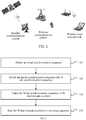
- FIG. 1 is a system architectural diagram of a synchronization signal sending method according to an embodiment of this application.
- the synchronization signal sending method provided in this embodiment of this application may be applied to a communications system whose transmit end and receive end need to be synchronized.
- a typical communications system includes a satellite communications system, a wireless communications system, and a wireless local area network.
- the satellite communications system usually includes a satellite end and a terrestrial end.
- the satellite end is used as a relay station in space, and amplifies an electromagnetic wave that is sent by a terrestrial station, and then returns the amplified electromagnetic wave to another terrestrial station.
- the terrestrial station is an interface between a satellite and a terrestrial public network.
- the wireless communications system usually includes three parts: a sending device, a receiving device, and a radio channel.
- Different wireless communications systems include different devices.
- devices that are included in a Long Term Evolution (Long Term Evolution, LTE) communications system include an evolved base station (eNodeB) and a terminal
- devices that are included in an Enterprise Internet of Things (Enterprise Internet of Things, eIoT) communications system include a base station and a terminal.
- LTE Long Term Evolution
- eNodeB evolved base station
- eIoT Enterprise Internet of Things
- the wireless local area network (Wireless Local Area Networks, WLAN) is a local area network in which a twisted pair copper wire is replaced with an electromagnetic wave.
- Devices in the wireless local area network include a wireless router and a terminal.
- the terminal provided in this embodiment of this application may be a wireless terminal such as a mobile phone or a tablet computer.
- the wireless terminal includes a device providing a voice and/or data service to a user.
- the terminal may further be a handheld device, an in-vehicle device, a wearable device, and a computing device having a wireless connection function, and various user equipments UEs, mobile stations (Mobile Station, MS for short), and terminals (terminal). This is not limited in this embodiment of this application.
- the base station and the wireless router provided in this embodiment of this application may be any device having management of wireless network resources. This is not limited in this embodiment of this application.
- the synchronization signal sending method provided in this embodiment of this application is mainly applied to a scenario in which a synchronization signal is carried in a plurality of symbols in a narrowband communications system, to resolve a technical problem in the prior art that currently a synchronization bandwidth is not fully used and synchronization performance is impaired after redundancy elimination and bandwidth limitation operations are performed on the synchronization signal.
- FIG. 2 is a flowchart of Embodiment 1 of a synchronization signal sending method according to an embodiment of this application.
- the synchronization signal sending method provided in this embodiment of this application may be performed by a synchronization signal sending apparatus.
- the synchronization signal sending apparatus varies with different communications systems.
- the synchronization signal sending apparatus may be an evolved base station, a base station, a micro base station, a wireless router, or a terrestrial station.
- the synchronization signal sending method provided in this embodiment of this application may include the following steps.
- Step 101 Obtain an initial synchronization sequence.
- a spectrum width corresponding to the initial synchronization sequence is greater than a bandwidth of a synchronization channel and is less than a sum of the bandwidth of the synchronization channel and a system protection bandwidth;
- a specific implementation for obtaining the initial synchronization sequence is not specially limited in this embodiment of this application, and existing methods may be used for obtaining initial synchronization sequences for different communications systems. For example, for an LTE communications system or an eIoT communications system, the synchronization signal sending apparatus may select an initial synchronization sequence in a preset synchronization sequence candidate set.
- Step 102 Divide the initial synchronization sequence into N sub-synchronization sequences.
- N is a quantity of time-domain symbols occupied by a synchronization signal, and N is an integer greater than 1.
- Step 103 Carry the N sub-synchronization sequences on N time-domain symbols.
- Each sub-synchronization sequence is carried in one time-domain symbol.
- Step 104 Send the N time-domain symbols to a receiving apparatus.
- the spectrum width corresponding to the initial synchronization sequence is greater than the bandwidth of the synchronization channel and is less than the sum of the bandwidth of the synchronization channel and the system protection bandwidth. Based on a system synchronization bandwidth, a margin is reserved for redundancy elimination of the synchronization signal.
- the initial synchronization sequence provided in this embodiment of this application fully uses the system synchronization bandwidth and the system protection bandwidth, so that a length of the initial synchronization sequence is increased and a correlation is better. After operations such as redundancy elimination and bandwidth limitation are performed, a bandwidth loss of the synchronization signal can be reduced, and utilization and synchronization performance of the system synchronization bandwidth are improved.
- bandwidth of the synchronization channel and the system protection bandwidth are not specifically limited in this embodiment of this application, and vary with different communications systems.
- a specific implementation for carrying the N sub-synchronization sequences on the N time-domain symbols in step 103 is not specially limited in this embodiment of this application, and varies with different communications systems, and existing signal processing methods in the different communications systems can be used.
- the synchronization sequence is not specially limited in this embodiment of this application, and is set based on a need.
- the synchronization sequence may be a ZC sequence.
- the method provided in this embodiment of this application may further include: performing upsampling on the initial synchronization sequence.
- a length L of the initial synchronization sequence may satisfy: ( BW sync + M ⁇ BW subcarrier ) ⁇ T sync > L > BW sync ⁇ T sync .
- BW sync represents the bandwidth of the synchronization channel
- BW subcarrier represents a subcarrier bandwidth
- T sync represents duration of the synchronization signal
- M BW protect / BW subcarrier
- BW protect represents the system protection bandwidth.
- a length L of the initial synchronization sequence may satisfy: BW sync BW subcarrier + M ⁇ N > L > BW sync BW subcarrier ⁇ N .
- a maximum value of M may be 2.
- FIG. 3 is a schematic structural diagram of a synchronization signal of an eIoT system in Embodiment 1 of a synchronization signal sending method according to an embodiment of this application.
- a time-domain symbol used by the eIoT system is an OFDM symbol.
- a total bandwidth of a system channel is 180 kHz
- a bandwidth of a synchronization channel is 60 kHz
- a subcarrier bandwidth is 15 kHz.
- the system includes 12 subcarriers.
- the system uses four subcarriers in a middle position of the channel to carry synchronization information.
- a synchronization signal is formed by 14 consecutive OFDM symbols, and duration of the synchronization signal is 1 ms.
- a system protection bandwidth is 30 kHz.
- BW sync 60 kHz
- BW subcarrier 15 kHz
- BW protect 30 kHz
- N 14
- T sync 1 ms
- the initial synchronization sequence is divided into 14 sub-synchronization sequences to be sequentially mapped to 14 OFDM symbols.
- Fast Fourier transformation (Fast Fourier Transformation, FFT) is first performed on each sub-synchronization sequence, and then inverse fast Fourier transform (Inverse Fast Fourier Transform, IFFT) IFFT is performed.
- FFT Fast Fourier Transformation
- IFFT inverse fast Fourier transform
- IFFT inverse Fast Fourier transform
- the base station combines the 14 sub-synchronization sequences on which signal processing has been performed, to form a to-be-sent synchronization signal.
- An initial synchronization sequence used by the existing eIoT system is a ZC sequence whose length is 59.
- the length L of the initial synchronization sequence may satisfy 90 > L > 60.
- the length L of the initial synchronization sequence may satisfy 84 > L > 56.
- the initial synchronization sequence is a ZC sequence whose length is 79 is used in this embodiment of this application.
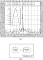
- FIG. 4 is an alignment diagram of spectrum widths corresponding to synchronization sequences of different lengths in Embodiment 1 of a synchronization signal sending method according to an embodiment of this application.
- FIG. 5 is an alignment diagram of related performance of synchronization sequences of different lengths in Embodiment 1 of a synchronization signal sending method according to an embodiment of this application.
- the ZC sequence whose length is 59 is used in the prior art, and a synchronization bandwidth that actually corresponds to a generated synchronization signal is 51 kHz. Consequently, a bandwidth of 60 kHz of the synchronization channel provided by a system is not fully used.
- the ZC sequence whose length is 79 has better autocorrelation performance than the ZC sequence whose length is 59, thereby improving synchronization performance of the system.
- This embodiment of this application provides the synchronization signal sending method, including: obtaining the initial synchronization sequence; dividing the initial synchronization sequence into the N sub-synchronization sequences; carrying the N sub-synchronization sequences on the N time-domain symbols; and sending the N time-domain symbols to the receiving apparatus.
- the system synchronization bandwidth and the system protection bandwidth are fully used, so that the length of the initial synchronization sequence is increased and a correlation is better. After operations such as redundancy elimination and bandwidth limitation are performed, a bandwidth loss of the synchronization signal can be reduced, and utilization and synchronization performance of the system synchronization bandwidth are improved.
- FIG. 6 is a schematic structural diagram of Embodiment 1 of a synchronization signal sending apparatus according to an embodiment of this application.
- the synchronization signal sending apparatus provided in this embodiment of this application varies with different communications systems.
- the synchronization signal sending apparatus may be an evolved base station, a base station, a micro base station, a wireless router, or a terrestrial station, and can perform the synchronization signal sending method provided in the embodiments shown in FIG. 2 to FIG. 5 .
- the synchronization signal sending apparatus provided in this embodiment of this application may include a processing module 12 and a transceiver module 11.
- the processing module 12 is configured to: obtain an initial synchronization sequence, where a spectrum width corresponding to the initial synchronization sequence is greater than a bandwidth of a synchronization channel and is less than a sum of the bandwidth of the synchronization channel and a system protection bandwidth; divide the initial synchronization sequence into N sub-synchronization sequences, where N is a quantity of time-domain symbols occupied by a synchronization signal, and N is an integer greater than 1; and carry the N sub-synchronization sequences on the N time-domain symbols, where each sub-synchronization sequence is carried in one time-domain symbol.
- the transceiver module 11 is configured to send the N time-domain symbols to a receiving apparatus.
- a length L of the initial synchronization sequence satisfies: ( BW sync + M ⁇ BW subcarrier ) ⁇ T sync > L > BW sync ⁇ T sync .
- BW sync represents the bandwidth of the synchronization channel
- BW subcarrier represents a subcarrier bandwidth
- T sync represents duration of the synchronization signal
- M BW protect / BW subcarrier
- BW protect represents the system protection bandwidth.
- a length L of the initial synchronization sequence satisfies: BW sync BW subcarrier + M ⁇ N > L > BW sync BW subcarrier ⁇ N .
- a maximum value of M is 2.
- the processing module 12 is further configured to perform upsampling on the initial synchronization sequence before dividing the initial synchronization sequence into the N sub-synchronization sequences.
- the synchronization signal sending apparatus provided in this embodiment of this application is configured to perform the synchronization signal sending method provided in the method embodiments shown in FIG. 2 to FIG. 5 , their technical principles and the technical effects are similar, and details are not described herein again.
- FIG. 7 is a schematic structural diagram of Embodiment 2 of a synchronization signal sending apparatus according to an embodiment of this application.
- the synchronization signal sending apparatus provided in this embodiment of this application varies with different communications systems.
- the synchronization signal sending apparatus may be an evolved base station, a base station, a micro base station, a wireless router, or a terrestrial station, and can perform the synchronization signal sending method provided in the embodiments shown in FIG. 2 to FIG. 5 .
- the synchronization signal sending apparatus provided in this embodiment of this application may include a processor 22 and a transceiver 21.
- the processor 22 is configured to: obtain an initial synchronization sequence, where a spectrum width corresponding to the initial synchronization sequence is greater than a bandwidth of a synchronization channel and is less than a sum of the bandwidth of the synchronization channel and a system protection bandwidth; divide the initial synchronization sequence into N sub-synchronization sequences, where N is a quantity of time-domain symbols occupied by a synchronization signal, and N is an integer greater than 1; and carry the N sub-synchronization sequences on the N time-domain symbols, where each sub-synchronization sequence is carried in one time-domain symbol.
- the transceiver 21 is configured to send the N time-domain symbols to a receiving apparatus.
- a length L of the initial synchronization sequence satisfies: ( BW sync + M ⁇ BW subcarrier ) ⁇ T sync > L > BW sync ⁇ T sync .
- BW sync represents the bandwidth of the synchronization channel
- BW subcarrier represents a subcarrier bandwidth
- T sync represents duration of the synchronization signal
- M BW protect / BW subcarrier
- BW protect represents the system protection bandwidth.
- a length L of the initial synchronization sequence satisfies: BW sync BW subcarrier + M ⁇ N > L > BW sync BW subcarrier ⁇ N .
- a maximum value of M is 2.
- the processor 22 is further configured to perform upsampling on the initial synchronization sequence before dividing the initial synchronization sequence into the N sub-synchronization sequences.
- the synchronization signal sending apparatus provided in this embodiment is configured to perform the synchronization signal sending method provided in the method embodiments shown in FIG. 2 to FIG. 5 , their technical principles and the technical effects are similar, and details are not described herein again.
- an embodiment of this application provides a computer-readable storage medium.
- the computer-readable storage medium stores a computer execution instruction.
- the synchronization signal sending apparatus performs the synchronization signal sending method provided in the method embodiments shown in FIG. 2 to FIG. 5 .
- an embodiment of this application provides a computer program product.
- the computer program product includes a computer execution instruction, and the computer execution instruction is stored in a computer-readable storage medium.
- At least one processor of a synchronization signal sending apparatus may read the computer execution instruction from the computer-readable storage medium, and the at least one processor executes the computer execution instruction, so that the synchronization signal sending apparatus performs the synchronization signal sending method provided in the method embodiments shown in FIG. 2 to FIG. 5 .
- FIG. 8 is a schematic structural diagram of Embodiment 1 of a communications system according to an embodiment of this application.
- the communications system provided in this embodiment of this application may include the synchronization signal sending apparatus 31 provided in the embodiment shown in FIG. 6 and a receiving apparatus 32, or the synchronization signal sending apparatus 31 provided in the embodiment shown in FIG. 7 and a receiving apparatus 32.
- the synchronization signal sending apparatus 31 and the receiving apparatus 32 vary with different communications systems.
- the synchronization signal sending apparatus 31 may be an evolved base station, a base station, a micro base station, a wireless router, or a terrestrial station.
- the receiving apparatus 32 may be a terminal, a satellite end, or the like.
- the synchronization signal sending apparatus in the communications systems provided in this embodiment is configured to perform the synchronization signal sending method provided in the method embodiments shown in FIG. 2 to FIG. 5 , their technical principles and the technical effects are similar, and details are not described herein again.
Landscapes
- Engineering & Computer Science (AREA)
- Computer Networks & Wireless Communication (AREA)
- Signal Processing (AREA)
- Mobile Radio Communication Systems (AREA)
- Time-Division Multiplex Systems (AREA)
Applications Claiming Priority (2)
| Application Number | Priority Date | Filing Date | Title |
|---|---|---|---|
| CN201611174894.1A CN108207025B (zh) | 2016-12-19 | 2016-12-19 | 同步信号发送方法和装置 |
| PCT/CN2017/115330 WO2018113540A1 (zh) | 2016-12-19 | 2017-12-08 | 同步信号发送方法和装置 |
Publications (2)
| Publication Number | Publication Date |
|---|---|
| EP3547767A1 true EP3547767A1 (de) | 2019-10-02 |
| EP3547767A4 EP3547767A4 (de) | 2019-12-11 |
Family
ID=62601802
Family Applications (1)
| Application Number | Title | Priority Date | Filing Date |
|---|---|---|---|
| EP17885213.3A Withdrawn EP3547767A4 (de) | 2016-12-19 | 2017-12-08 | Verfahren und vorrichtung zum senden von synchronisationssignalen |
Country Status (6)
| Country | Link |
|---|---|
| US (1) | US10805890B2 (de) |
| EP (1) | EP3547767A4 (de) |
| JP (1) | JP2020512709A (de) |
| CN (1) | CN108207025B (de) |
| MX (1) | MX2019007195A (de) |
| WO (1) | WO2018113540A1 (de) |
Family Cites Families (14)
| Publication number | Priority date | Publication date | Assignee | Title |
|---|---|---|---|---|
| CN101238666B (zh) * | 2005-08-22 | 2011-06-01 | 松下电器产业株式会社 | 基站装置以及移动台装置 |
| US7706249B2 (en) * | 2006-02-08 | 2010-04-27 | Motorola, Inc. | Method and apparatus for a synchronization channel in an OFDMA system |
| US7911935B2 (en) * | 2006-02-08 | 2011-03-22 | Motorola Mobility, Inc. | Method and apparatus for interleaving sequence elements of an OFDMA synchronization channel |
| CN102695226B (zh) * | 2006-09-28 | 2014-12-03 | 富士通株式会社 | 移动站和无线通信系统 |
| CN100584104C (zh) * | 2007-01-26 | 2010-01-20 | 华为技术有限公司 | 一种业务调度系统和方法 |
| US9344314B2 (en) | 2007-04-24 | 2016-05-17 | Texas Instruments Incorporated | Computer generated sequences for downlink and uplink signals in wireless communication systems |
| US8189697B2 (en) * | 2008-10-01 | 2012-05-29 | Harris Corporation | Orthogonal frequency division multiplexing (OFDM) communications device and method that incorporates low PAPR preamble and receiver channel estimate circuit |
| EP2339761B1 (de) * | 2009-12-22 | 2012-07-11 | Mitsubishi Electric R&D Centre Europe B.V. | Verfahren zur Synchronisation von Knoten |
| CN102098266B (zh) * | 2011-03-25 | 2014-12-10 | 东南大学 | 多输入多输出正交频分复用系统同步序列构造方法 |
| WO2013027090A1 (en) * | 2011-08-23 | 2013-02-28 | Nokia Corporation | Method and apparatus for physical cell identification split handling |
| US9917616B2 (en) | 2013-01-17 | 2018-03-13 | Telefonaktiebolaget L M Ericsson (Publ) | Synchronization signal design for wireless devices in a long range extension mode |
| CN103078825B (zh) * | 2013-01-30 | 2016-08-10 | 清华大学 | 数字通信系统中的帧同步序列生成方法及装置 |
| US9350379B1 (en) * | 2015-01-15 | 2016-05-24 | Huawei Technologies Co., Ltd. | System and method for data conversion of signals using noise shaping |
| JPWO2017033841A1 (ja) * | 2015-08-21 | 2018-06-14 | 株式会社Nttドコモ | ユーザ端末、無線基地局及び無線通信方法 |
-
2016
- 2016-12-19 CN CN201611174894.1A patent/CN108207025B/zh active Active
-
2017
- 2017-12-08 WO PCT/CN2017/115330 patent/WO2018113540A1/zh not_active Ceased
- 2017-12-08 EP EP17885213.3A patent/EP3547767A4/de not_active Withdrawn
- 2017-12-08 MX MX2019007195A patent/MX2019007195A/es unknown
- 2017-12-08 JP JP2019532992A patent/JP2020512709A/ja not_active Withdrawn
-
2019
- 2019-06-18 US US16/444,859 patent/US10805890B2/en not_active Expired - Fee Related
Also Published As
| Publication number | Publication date |
|---|---|
| CN108207025B (zh) | 2020-12-22 |
| WO2018113540A1 (zh) | 2018-06-28 |
| MX2019007195A (es) | 2019-11-18 |
| EP3547767A4 (de) | 2019-12-11 |
| CN108207025A (zh) | 2018-06-26 |
| JP2020512709A (ja) | 2020-04-23 |
| US10805890B2 (en) | 2020-10-13 |
| US20190306818A1 (en) | 2019-10-03 |
Similar Documents
| Publication | Publication Date | Title |
|---|---|---|
| US20210219250A1 (en) | Information transmission method and information transmission apparatus | |
| EP3334058B1 (de) | Verfahren und vorrichtung zum senden oder empfangen eines signals | |
| CN104125184B (zh) | 一种导频信号的传输方法及设备 | |
| EP4280554A2 (de) | Verfahren zur übertragung einer he-ltf-sequenz und vorrichtung | |
| CN101162987B (zh) | 一种时分双工系统上行特殊时隙中导频信号的发送方法 | |
| EP3496310A1 (de) | Signalsendevorrichtung, signaldetektionsvorrichtung und verfahren | |
| CN102238110B (zh) | 多用户信道估计方法及装置 | |
| EP3445011B1 (de) | Signalverarbeitungsverfahren und -vorrichtung | |
| Medjahdi et al. | Wola processing: A useful tool for windowed waveforms in 5G with relaxed synchronicity | |
| WO2018064909A1 (zh) | 干扰源小区定位方法和装置以及对应的基站 | |
| CN108289069A (zh) | 一种参考信号的传输方法、发送端和接收端 | |
| EP3833058A1 (de) | Verfahren und vorrichtung zur erzeugung eines positionierungsreferenzsignals, kommunikationssystem und speichermedium | |
| KR20240005066A (ko) | 데이터 전송 방법, 장치, 전자 설비 및 저장 매체 기술분야 | |
| EP3742692B1 (de) | Ressourcenkartierungsverfahren und kommunikationsvorrichtung | |
| WO2018058678A1 (zh) | 一种信号处理方法及设备 | |
| US10805890B2 (en) | Synchronization signal sending method and apparatus | |
| EP4221034B1 (de) | Referenzsignalübertragungsverfahren und -vorrichtung, kommunikationsknoten und speichermedium | |
| CN103988565B (zh) | 随机接入方法、用户设备、基站及系统 | |
| CN104052704A (zh) | 数据发送和接收方法及设备 | |
| WO2017211285A1 (zh) | 信息发送方法及装置、用户设备和基站 | |
| WO2024240037A1 (zh) | 信号传输方法、装置、信号发送设备及信号接收设备 | |
| WO2018171809A1 (zh) | 配置方法及装置、计算机存储介质 |
Legal Events
| Date | Code | Title | Description |
|---|---|---|---|
| STAA | Information on the status of an ep patent application or granted ep patent |
Free format text: STATUS: THE INTERNATIONAL PUBLICATION HAS BEEN MADE |
|
| PUAI | Public reference made under article 153(3) epc to a published international application that has entered the european phase |
Free format text: ORIGINAL CODE: 0009012 |
|
| STAA | Information on the status of an ep patent application or granted ep patent |
Free format text: STATUS: REQUEST FOR EXAMINATION WAS MADE |
|
| 17P | Request for examination filed |
Effective date: 20190627 |
|
| AK | Designated contracting states |
Kind code of ref document: A1 Designated state(s): AL AT BE BG CH CY CZ DE DK EE ES FI FR GB GR HR HU IE IS IT LI LT LU LV MC MK MT NL NO PL PT RO RS SE SI SK SM TR |
|
| AX | Request for extension of the european patent |
Extension state: BA ME |
|
| A4 | Supplementary search report drawn up and despatched |
Effective date: 20191111 |
|
| RIC1 | Information provided on ipc code assigned before grant |
Ipc: H04W 56/00 20090101ALI20191105BHEP Ipc: H04L 27/26 20060101AFI20191105BHEP |
|
| DAV | Request for validation of the european patent (deleted) | ||
| DAX | Request for extension of the european patent (deleted) | ||
| STAA | Information on the status of an ep patent application or granted ep patent |
Free format text: STATUS: THE APPLICATION HAS BEEN WITHDRAWN |
|
| 18W | Application withdrawn |
Effective date: 20201208 |