EP3547794A1 - Basisstation und endgerätevorrichtung - Google Patents
Basisstation und endgerätevorrichtung Download PDFInfo
- Publication number
- EP3547794A1 EP3547794A1 EP17873179.0A EP17873179A EP3547794A1 EP 3547794 A1 EP3547794 A1 EP 3547794A1 EP 17873179 A EP17873179 A EP 17873179A EP 3547794 A1 EP3547794 A1 EP 3547794A1
- Authority
- EP
- European Patent Office
- Prior art keywords
- base station
- backhaul
- wireless communication
- connection
- interface
- Prior art date
- Legal status (The legal status is an assumption and is not a legal conclusion. Google has not performed a legal analysis and makes no representation as to the accuracy of the status listed.)
- Granted
Links
Images











Classifications
-
- H—ELECTRICITY
- H04—ELECTRIC COMMUNICATION TECHNIQUE
- H04W—WIRELESS COMMUNICATION NETWORKS
- H04W84/00—Network topologies
- H04W84/02—Hierarchically pre-organised networks, e.g. paging networks, cellular networks, WLAN [Wireless Local Area Network] or WLL [Wireless Local Loop]
- H04W84/04—Large scale networks; Deep hierarchical networks
- H04W84/042—Public Land Mobile systems, e.g. cellular systems
- H04W84/047—Public Land Mobile systems, e.g. cellular systems using dedicated repeater stations
-
- H—ELECTRICITY
- H04—ELECTRIC COMMUNICATION TECHNIQUE
- H04W—WIRELESS COMMUNICATION NETWORKS
- H04W16/00—Network planning, e.g. coverage or traffic planning tools; Network deployment, e.g. resource partitioning or cells structures
- H04W16/24—Cell structures
- H04W16/26—Cell enhancers or enhancement, e.g. for tunnels, building shadow
-
- H—ELECTRICITY
- H04—ELECTRIC COMMUNICATION TECHNIQUE
- H04W—WIRELESS COMMUNICATION NETWORKS
- H04W68/00—User notification, e.g. alerting and paging, for incoming communication, change of service or the like
- H04W68/02—Arrangements for increasing efficiency of notification or paging channel
-
- H—ELECTRICITY
- H04—ELECTRIC COMMUNICATION TECHNIQUE
- H04W—WIRELESS COMMUNICATION NETWORKS
- H04W72/00—Local resource management
- H04W72/50—Allocation or scheduling criteria for wireless resources
- H04W72/54—Allocation or scheduling criteria for wireless resources based on quality criteria
- H04W72/542—Allocation or scheduling criteria for wireless resources based on quality criteria using measured or perceived quality
-
- H—ELECTRICITY
- H04—ELECTRIC COMMUNICATION TECHNIQUE
- H04W—WIRELESS COMMUNICATION NETWORKS
- H04W76/00—Connection management
- H04W76/10—Connection setup
-
- H—ELECTRICITY
- H04—ELECTRIC COMMUNICATION TECHNIQUE
- H04W—WIRELESS COMMUNICATION NETWORKS
- H04W76/00—Connection management
- H04W76/20—Manipulation of established connections
- H04W76/27—Transitions between radio resource control [RRC] states
-
- H—ELECTRICITY
- H04—ELECTRIC COMMUNICATION TECHNIQUE
- H04W—WIRELESS COMMUNICATION NETWORKS
- H04W84/00—Network topologies
- H04W84/18—Self-organising networks, e.g. ad-hoc networks or sensor networks
-
- H—ELECTRICITY
- H04—ELECTRIC COMMUNICATION TECHNIQUE
- H04W—WIRELESS COMMUNICATION NETWORKS
- H04W92/00—Interfaces specially adapted for wireless communication networks
- H04W92/04—Interfaces between hierarchically different network devices
- H04W92/14—Interfaces between hierarchically different network devices between access point controllers and backbone network device
-
- H—ELECTRICITY
- H04—ELECTRIC COMMUNICATION TECHNIQUE
- H04B—TRANSMISSION
- H04B7/00—Radio transmission systems, i.e. using radiation field
- H04B7/24—Radio transmission systems, i.e. using radiation field for communication between two or more posts
- H04B7/26—Radio transmission systems, i.e. using radiation field for communication between two or more posts at least one of which is mobile
- H04B7/2603—Arrangements for wireless physical layer control
- H04B7/2606—Arrangements for base station coverage control, e.g. by using relays in tunnels
-
- H—ELECTRICITY
- H04—ELECTRIC COMMUNICATION TECHNIQUE
- H04W—WIRELESS COMMUNICATION NETWORKS
- H04W92/00—Interfaces specially adapted for wireless communication networks
- H04W92/04—Interfaces between hierarchically different network devices
- H04W92/12—Interfaces between hierarchically different network devices between access points and access point controllers
Definitions
- the present disclosure relates to a base station and a terminal device.
- a base station In a cellular system, a base station is connected to a core network via backhaul and provides wireless services to slave terminal devices on the basis of control using the core network.
- the backhaul is typically formed on a wired communication path, replacement of a part of a communication path with a wireless communication path has been studied in recent years. In particular, studies regarding backhaul including a wireless communication path using a so-called millimeter waveband (a high frequency band from a 30 to 70 GHz band) have progressed.
- Patent Literature 1 discloses a technology of constructing an autonomous distributed network by transmitting beacons between access points in a wireless system other than a cellular system.
- Patent Literature 1 JP 2007-129772A
- backhaul In an environment in which a wired communication path is assumed, backhaul is fixedly provided, and a route, an operating method, and the like are not dynamically changed. However, in a case in which the backhaul is formed to include a wireless communication path, it is desirable that backhaul be able to be flexibly constructed in accordance with movement of a base station, a change in environment, or the like.
- the present disclosure provides a mechanism capable of flexibly constructing backhaul including a wireless communication path.
- a base station including: a processing unit that is connected to backhaul including a first logical interface with a first control entity related to a control plane and a second logical interface with a second control entity related to a user plane. Both a communication route in which the first logical interface is formed and a communication route in which the second logical interface is formed include wireless communication paths formed between a first base station and a second base station.
- a base station including: a processing unit that is connected to backhaul including a first logical interface with a control entity related to a control plane using a wireless communication path to another base station and that provides a notification of information related to the backhaul while including the information in system information.
- a base station including: a processing unit that performs authentication processing for connecting to backhaul including a logical interface with a control entity using a wireless communication path to a first base station that is connected to the backhaul.
- a base station including: a processing unit that is connected to backhaul including a logical interface with a control entity using a wireless communication path to first base stations that are connected to the backhaul, relays connection of one or more second base stations on a downstream side to the backhaul using a wireless communication path to the second base stations, and provides a notification of a connection request for connection to the backhaul to a third base station using a wireless communication path to the third base station.
- a terminal device including: a processing unit that performs, on backhaul including a first logical interface with a control entity related to a control plane, processing based on information that is provided as a notification from a base station connected using a wireless communication path to another base station, that is included in system information, and that relates to the backhaul.
- a mechanism capable of flexibly constructing backhaul including a wireless communication path is provided.
- the effects described above are not necessarily limitative. With or in the place of the above effects, there may be achieved any one of the effects described in this specification or other effects that may be grasped from this specification.
- FIG. 1 is a diagram illustrating an overall configuration of the cellular system 1 according to the present embodiment.
- the cellular system 1 includes a plurality of base stations 100, a plurality of terminal devices 200, a core network (CN) 20, and the Internet 30.
- CN core network
- the base stations 100 operate cells 11 and provide a wireless service to one or more terminal devices 200 located in the cells 11.
- a base station 100A operates a cell 11A and provides a wireless service to a terminal device 200A.
- a base station 100B operates a cell 11B and provides a wireless service to a terminal device 200B.
- the cells 11 are operated in accordance with an arbitrary wireless communication scheme such as LTE or New Radio (NR), for example.
- the base stations 100 are connected to the core network 20.
- the core network 20 is connected to the Internet 30 via a gateway device (not illustrated).
- a network between the base stations 100 and the core network 20 is also referred to as a backhaul link or backhaul.
- a network between the base stations 100 and the terminal devices 200 is also referred to as an access link.
- the backhaul is formed on a wired communication path
- the access link is formed on a wireless communication path.
- the base station 100B is connected to the core network 20 in a wired manner.
- the backhaul is connected by way of a wireless communication path (that is, a wireless relay).
- the base station 100A is connected to the core network 20 using a wireless communication path to the base station 100B.
- the base station 100A is connected to the backhaul using the wireless communication path to the base station 100B.
- a technology related to a base station connected to backhaul using a wireless communication path to other base stations, such as the base station 100A, will mainly be disclosed.
- the terminal devices 200 perform wireless communication with the base stations 100 on the basis of control performed by the base stations 100. For example, the terminal devices 200 transmit uplink signals to the base stations 100 and receive downlink signals from the base stations 100.
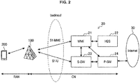
- FIG. 2 is a diagram for explaining the backhaul according to the present embodiment.
- the cellular system 1 includes a radio access network (RAN) and the CN (core network 20).
- the RAN is a network formed by the base stations 100 and the terminal devices 200, and the base stations 100 and the terminal devices 200 are connected to each other with a wireless interface.
- the interface is also referred to as a Uu interface.
- the core network 20 includes control entities such as a mobility management entity (MME) 21, a home subscriber server (HSS) 22, a serving gateway (S-GW) 23, and a packet data network gateway (P-GW) 24.
- MME mobility management entity
- HSS home subscriber server
- S-GW serving gateway
- P-GW packet data network gateway
- the MME 21 and the HSS 22 are control entities related to a control plane.
- the MME 21 performs session management when communication is started.
- the HSS 22 stores subscriber contract information.
- the S-GW 23 and the P-GW 24 are control entities related to a user plane.
- the S-GW 23 serves as an anchor point when the terminal devices 200 perform handover between the base stations 100.
- the P-GW 24 is a connection point between the Internet 30 and the core network 20.
- the backhaul connecting the base stations 100 and the core network 20 includes an S1-MME interface between the base stations 100 and the MME 21 and an S1-U interface between the base stations 100 and the S-GW 23.
- the S1-MME interface is an interface (corresponding to a first logical interface) with a control entity related to a control plane (for example, the MME 21), and a signal of the control plane is supplied thereto.
- the S1-U interface is an interface (corresponding to a second logical interface) with a control entity related to a user plane (for example, the S-GW 23) and is an interface to which a signal of the user plane is supplied. Therefore, it is possible to state that the backhaul includes the S1-MME interface that is backhaul of the control plane and the S1-U interface that is backhaul of the user plane.
- FIG. 3 is a diagram for explaining the backhaul according to the present embodiment.
- backhaul is formed by way of a wireless communication path between the base stations 100.
- traffic of the base station 100A to the core network 20 reaches the core network 20 by way of a wireless communication path between a base station 100A and a base station 100B and a wireless communication path between the base station 100B and a base station 100C.
- each base station 100 that relays the communication between the base station 100 on the downstream side and the backhaul performs relay for the base station 100 on the downstream side while providing a wireless service to the terminal devices 200 using an ordinary subscriber-based wireless access interface such as LTE or HSDPA.
- Such backhaul is also considered to be able to be configured by simply replacing a part of the communication routes in which the S1-MME interface and the S1-U interface are formed with a wireless communication path. In such a case, it is not necessary to change an existing protocol on the assumption of wired connection. However, since such backhaul is fixedly provided, it is difficult to dynamically change the route and/or an operation state.
- an S2 setup procedure is used.
- an example of a flow of the S1 setup procedure will be described with reference to FIG. 4 .
- FIG. 4 is a sequence diagram illustrating an example of a flow of a typical S1 setup procedure.
- the base station 100 and the MME 21 are involved in this sequence.
- the base station 100 transmits an S1 setup request to the MME 21 (Step S102).
- the base station 100 transmits the S1 setup request to the MME 21 using a known default IP address of the MME 21.
- the MME 21 transmits an S1 setup response to the base station 100 in a case in which the MME 21 accepts the base station 100 (Step S104).
- the S1 setup procedure is conceivable even when the backhaul including wireless communication paths is used.
- the S1 setup procedure is based on the assumption of execution between the base station 100 and the MME 21 connected in a wired manner, between which connection is not lost.
- the backhaul including the wireless communication paths is applied to smaller-scaled base stations, for example, a case in which the wireless communication paths between the small-scaled base stations are blocked by objects, traveling vehicles, and the like is conceivable. Further, if the backhaul including the wireless communication paths is widely distributed, frequency bands used for the backhaul are limited, and this may lead to interference.
- the S1-MME interface and the S1-U interface cases similar to the aforementioned case of the connection failure may occur.
- the S1-MME interface is established.
- the S1-U interface is established between the P-GW 24 and the base station 100 designated by the MME 21.
- the connection failure in the S1 set up is substantially synonymous with the connection failure in the S1-MME. This is because the S1-AP protocol for the S1 setup is a protocol in the S1-MME interface.
- protocol stacks of the S1-MME interface and the S1-U interface will be described with reference to FIGS. 5 and 6 .
- FIG. 5 is a diagram illustrating a protocol stack of the S1-MME interface.
- the protocol stack of the S1-MME interface includes L1, L2, an Internet protocol (IP), a stream control transmission protocol (SCTP), S1-AP, and a non-access stratum (NAS).
- L1 and L2 are protocols that provide a wireless interface.
- IP is an Internet protocol.
- SCTP is a protocol that realizes retransmission.
- S1-AP is a protocol for a signal procedure between the base station 100 and the MME 21.
- S1-AP is established by the S1 setup.
- NAS is a protocol for signal exchange between a terminal device 200 and the MME 21. On the basis of the above description, it is possible to recognize the protocol stack from L1 to S1-AP as backhaul for carrying NAS.
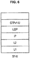
- FIG. 6 is a diagram illustrating a protocol stack of the S1-U interface.
- the protocol stack of the S1-U interface includes L1, L2, IP, a user datagram protocol (UDP), and a general packet radio service (GPRS) tunneling protocol (GTP) v1-U.
- UDP is a protocol that does not perform retransmission.
- GTPv1-U is a tunneling protocol between a terminal device 200 and the S-GW 23. Note that the tunneling protocol is a protocol for placing an arbitrary protocol on a protocol.
- GTPv1-U is established for each terminal device 200 when the terminal device 200 is connected to a network, and user data is exchanged on GTPv1-U.
- the protocol stack from L1 to UDP as backhaul for carrying GTPv1-U and user data thereon.
- FIG. 7 is a block diagram illustrating an example of a configuration of the base station 100 according to an embodiment of the present disclosure.
- the base station 100 includes an antenna unit 110, a wireless communication unit 120, a network communication unit 130, a storage unit 140, and a processing unit 150.
- the antenna unit 110 radiates a signal output from the wireless communication unit 120 into a space as a radio wave. Further, the antenna unit 110 converts the radio wave in the space into a signal and outputs the signal to the wireless communication unit 120.
- the wireless communication unit 120 transmits and receives signals. For example, the wireless communication unit 120 transmits a downlink signal to the terminal device and receives an uplink signal from the terminal device.
- the network communication unit 130 transmits and receives information.
- the network communication unit 130 transmits information to other nodes and receives information from other nodes.
- the other nodes include other base stations and core network nodes.
- the storage unit 140 temporarily or permanently stores a program and various data for an operation of the base station 100.
- the processing unit 150 provides various functions of the base station 100.
- the processing unit 150 includes a backhaul control unit 151 and a communication control unit 153.
- the backhaul control unit 151 performs control related to the backhaul.
- the backhaul control unit 151 provides a notification of information related to the backhaul to other base stations 100 or terminal devices 200 or controls connection to the backhaul via the wireless communication paths that is provided from other base stations 100 or to other base stations 100.
- the communication control unit 153 provides a wireless service to a terminal device 200 which is connected to the communication control unit 153 itself.
- the processing unit 150 may further include other components than the above-described components. In other words, the processing unit 150 may also perform operations other than the operations of the above-described components.
- FIG. 8 is a block diagram illustrating an example of a configuration of the terminal device 200 according to an embodiment.
- the terminal device 200 includes an antenna unit 210, a wireless communication unit 220, a storage unit 230, and a processing unit 240.
- the antenna unit 210 radiates a signal output from the wireless communication unit 220 into a space as a radio wave. Further, the antenna unit 210 converts the radio wave in the space into a signal and outputs the signal to the wireless communication unit 220.
- the wireless communication unit 220 transmits and receives signals. For example, the wireless communication unit 220 receives a downlink signal from the base station and transmits an uplink signal to the base station.
- the storage unit 230 temporarily or permanently stores a program and various data for an operation of the terminal device 200.
- the processing unit 240 provides various functions of the terminal device 200.
- the processing unit 240 includes an acquiring unit 241 and a communication control unit 243.
- the acquiring unit 241 acquires the information related to the backhaul that is included in system information provided as a notification from the base station 100, RRC signaling, or the like.
- the communication control unit 243 performs processing based on the information related to the backhaul. For example, the communication control unit 243 performs switching to another frequency resource or handover to other base stations 100.
- the processing unit 240 may further include other components than the above-described components. In other words, the processing unit 240 may also perform operations other than the operations of the above-described components.
- the S1-MME interface also includes a protocol for the S1 setup. Therefore, if the backhaul related to the S1-MME interface is formed to include a wireless communication path using a high frequency (for example, 70 GHz to 100 GHz) such as a millimeter waveband, it is considered that disadvantages may occur when a base station is registered in the MME. If connection between the base station and the MME becomes unstable, a state in which the base station is not registered in the MME occurs, and it becomes difficult for the terminal device to use the base station. This is because the base station typically stops transmission of all signals including basic signals such as signals for synchronization and system information indicating performance of the base station in a case in which the connection to the MME has been lost. In consideration of the fact that the backhaul is relayed in multiple stages (multi-hopping) by the wireless communication paths between the base stations 100, it is desirable that the number of the relay stages be smaller.
- a high frequency for example, 70 GHz to 100 GHz
- a millimeter waveband
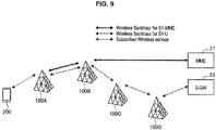
- FIG. 9 is a diagram for explaining technical features according to the present embodiment.
- the base station 100A forms each of the S1-MME interface and the S1-U interface on a communication route including a wireless communication path.
- the S1-MME interface is formed on a communication route by way of the base station 100B.
- the S1-U interface is formed on a communication route by way of base stations 100B, 100C, and 100D. Note that forming of the S1-MME interface or the S1-U interface is synonymous with connection to the S1-MME interface or the S1-U interface.
- Both the communication path in which the S1-MME interface is formed and the communication path in which the S1-U interface is formed may include the same wireless communication path.
- both the communication path in which the S1-MME interface is formed and the communication path in which the S1-U interface is formed include a wireless communication path that is formed between the base station 100A and the base station 100B. In this manner, the S1-MME interface and the S1-U interface may coexist on the same physical interface.
- the communication path in which the S1-MME interface is formed and the communication path in which the S1-U interface is formed may include mutually different wireless communication paths.
- the communication path in which the S1-U interface is formed includes a wireless communication path formed between the base station 100B and the base station 100C and a wireless communication path formed in the base station 100C and the base station 100D, unlike the communication path in which the S1-MME interface is formed.
- the S1-MME interface and the S1-U interface may be formed on different physical interfaces.
- signals of base stations 100 on the downstream side on which the number of relays from the MME 21 or the S-GW 23 is larger are multiplexed.
- a signal of the base station 100A, a signal of the base station 100B, and a signal of the base station 100C are multiplexed on the wireless communication path formed between the base station 100C and the base station 100D.
- the base station 100C multiplexes the signal of the base station 100C itself, the signal of the base station 100B, and the signal of the base station 100A and transmits or receives the multiplexed signals.
- the base stations 100 on the communication route in which the S1-MME interface or the S1-U interface is formed transparently transfer a signal from the downstream side to the upstream side or a signal from the upstream side to the downstream side.
- the base station 100B transparently transfers a signal to the MME 21, which has been received from the base station 100A, to the MME 21 and transparently transfers a signal to the base station 100A, which has been received from the MME 21, to the base station 100A.
- features of the backhaul including the wireless communication paths enable flexible construction of backhaul. For example, it is possible to use a common wireless communication path or different wireless communication paths among a plurality of interfaces and to perform more efficient communication through multiplexing and transparent transfer of packets.
- the base stations 100 are connected to the S1-MME interface by way of a smaller number of base stations as compared with those of the S1-U interface.
- the base station 100A is connected to the S1-MME interface by way of the base station 100B, namely by way of a smaller number of base stations than those of the S-U interface that is connected by way of the base stations 100B, 100C, and 100D.
- This may mean that the base station 100 selects other base stations 100 to which the base station 100 is connected by forming a wireless communication path for connection to the S1-MME interface in accordance with the number of base stations by way of which the base station 100 establishes connection.
- the base station 100 can connect to the S1-MME interface related to the control plane with higher priority than in the case of the S1-U interface related to the user plane via wireless relays in a smaller number of stages. In this manner, since stability of the S1-MME interface is improved, the base station 100 can stably provide a wireless service to the terminal devices 200.
- the reduction of the number of base stations 100 by way of which connection is established may also be described as utilization of a frequency resource of a lower frequency. In this regard, description will be given with reference to FIG. 10 .
- FIG. 10 is a diagram for explaining technical features according to the present embodiment.
- the base station 100 forms a wireless communication path for the S1-MME interface using a frequency resource (for example, a component carrier) of a lower frequency than that of the wireless communication path for the S1-U interface. Since a communicable distance increases as the frequency is lower, it is possible to realize reduction of the number of relay stages by using a frequency resource of a low frequency.
- the base station 100 can be connected to the S1-MME interface via wireless relays in a smaller number of stages by using a frequency resource of a low frequency. In this manner, since stability of the S1-MME interface is improved, the base station 100 can stably provide a wireless service to the terminal devices 200.
- the base station 100 executes the S1 setup procedure using the frequency resource of the lower frequency. Then, the base station 100 is connected to the S1-MME interface by way of other base stations 100 that are transmission destinations of an S1 setup request. Meanwhile, the base station 100 is connected to the S1-U interface using a frequency resource of a high frequency among frequency resources provided from other base stations 100 connected to the S-GW 23. Note that connection to the S1-MME interface by way of other base stations 100 may mean connection to the S1-MME interface to which other base stations 100 have already been connected. The same applies to the S1-U interface.
- the base station 100 may form the wireless communication path for the S1-MME interface using a frequency resource of a frequency that is less influenced by rainfall.
- the base station 100 forms the S1-MME interface while avoiding a frequency with large rainfall attenuation, such as a 70 GHz band or an 80 GHz band. In this manner, since stability of the S1-MME interface is improved, the base station 100 can stably provide a wireless service to the terminal devices 200.
- the base station 100 exchanges information related to a communication route in which the S1-MME interface or the S1-U interface is formed with other base stations 100.
- the exchanged information is also referred to as route information.
- the route information may include information regarding a frequency band requested in relation to wireless communication paths included in the communication route in which the backhaul is formed and a minimum frequency band or a maximum frequency band that is currently used in practice, for example.
- the route information may include at least any of a delay request, a signal-to-noise (SN) ratio request, or a reliability request in relation to the wireless communication paths included in the communication route in which the backhaul is formed.
- the route information may be separately managed for one related to the S1-MME interface and for one related to the S1-U interface.
- the base station 100 can be connected to the backhaul while avoiding other base stations 100 that may become unallowable bottleneck by the route information being exchanged among the base stations 100. Also, the base station 100 can select a frequency resource suitable for the connection to the backhaul on the basis of the exchanged route information.
- the route information may be periodically or nonperiodically exchanged.
- the base station 100 may include the route information in the S1 setup request.
- the route information may be exchanged not only when the wireless communication paths are established but also after the wireless communication paths are established. In the latter case, the base station 100 can perform maintenance such that more desirable backhaul is formed by changing the frequency resource used for the backhaul or the like.
- Table 1 illustrates that although utilization of component carriers of equal to or less than 26 GHz is requested for all the wireless communication paths included in the communication route, there is a wireless communication path using a component carrier of 50 GHz, in practice.
- the route information related to the S1-MME interface is separated from the route information related to the S1-U interface.
- the backhaul in each of the following embodiments is backhaul including the aforementioned wireless communication paths.
- the present embodiment is a mode in which base stations 100 connected to backhaul including wireless communication paths provide a stable wireless service to slave terminal devices 200 even if the wireless communication paths included in the backhaul are unstable.
- a typical base station stops transmission of all signals including basic signals such as signals for synchronization and system information indicating capability of the base station.
- basic signals such as signals for synchronization and system information indicating capability of the base station.
- an SCTP protocol has a function of Keep-Alive, periodically exchanges packets between the base station and the MME, and constantly monitors whether or not the line has been interrupted.
- the base station may fail in many cases even of the base station retransmits the S1 setup request. Since the base station stops the transmission of all the signals to the terminal devices during that time, the terminal devices connected to the base station have no choice other than giving up the connection to the base station once.
- the wireless service to the terminal devices be not stopped even in the case in which the wireless communication paths are unstable.
- the base station 100 transmits a predetermined signal to the terminal devices 200 until a predetermined time (corresponding to a first predetermined time) is reached.
- the predetermined signal include at least any of a reference signal, a synchronization signal, or system information.
- the reference signal described here may be an arbitrary downlink reference signal such as a cell-specific reference signal (CRS) or a channel state information reference signal (CSI-RS).
- the synchronization signal may be a primary synchronization signal (PSS) or a secondary synchronization signal (SSS), or the reference signal may be used as the synchronization signal.
- system information may be a master information block (MIB) or a system information block (SIB).
- MIB master information block
- SIB system information block
- the base station 100 is connected to the backhaul using the wireless communication paths to other base stations 100 and provides a notification of information related to the backhaul while including the information in the system information.
- the information related to the backhaul may include information indicating a state of the control plane.
- the information related to the backhaul may include information indicating that the S1-MME interface has been disconnected.
- the information indicating that the S1-MME interface has been disconnected may include information indicating that the connection is being restored before the aforementioned predetermined time is reached or may include information indicating that restoring has been failed after the predetermined time is reached.
- the information related to the backhaul may include information indicating a state of the user plane.
- the information related to the backhaul may include information indicating that the S1-U interface has been disconnected.
- the disconnection described here means that any of the wireless communication paths on the communication route in which the S1-MME interface or the S1-U interface is formed has been disconnected.
- Table 4 An example of a state of backhaul that is provided as a notification while being included in the system information is illustrated in Table 4 below.
- the base station 100 provides a notification of system information including that the state is the state B to the terminal devices 200.
- the S1-MME interface has been disconnected while the S1-U interface maintains satisfactory connection.
- the base station 100 continues the communication as long as it is not necessary to perform a procedure of a control system such as initial attachment, paging, or generation of a bearer corresponding to another QoS. In that case, the base station 100 can perform communication using the S1-U interface until a session that has already been established ends.
- the base station 100 performs downlink and uplink scheduling for it and continuously provides data transmission and reception services to the terminal devices 200.
- the initial attachment is a procedure of registering a terminal device 200 in a network in a case in which the terminal device 200 to which power supply has been stopped is turned on.
- the paging is a procedure of calling a telephone incoming call for the terminal devices 200.
- the base station 100 stops downlink data transmission in a case in which the S1-U interface has been disconnected. Also, the base station 100 may stop the downlink data transmission even in a case in which the connection to the S1-U interface is maintained if the S1-MME interface has been disconnected.
- the base station 100 In a case in which the S1-MME interface has been restored before the predetermined time is reached, the base station 100 returns to an ordinary state and continues the wireless service to the terminal devices 200. Meanwhile, in a case in which the predetermined time is reached without the S1-MME interface being restored, the base station 100 stops the transmission of the predetermined signal to the terminal devices 200.
- States of the terminal devices 200 may be either an RRC connection state or an RRC idle state until the S1-MME interface is restored or the predetermined time is reached after the S1-MME interface is disconnected.
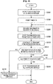
- FIG. 11 is a flowchart illustrating an example of a flow of processing when the S1-MME interface is disconnected, which is performed by the base station 100 according to the embodiment.
- the base station 100 if disconnection of the S1-MME interface is detected (Step S202), the base station 100 first starts a timer T1 (Step S204). Then, the base station 100 provides the information related to the backhaul to the terminal devices 200 while including the information in the system information (Step S206). Next, the base station 100 stops transmission and reception of user data (Step S208) and continues to transmit the synchronization signal (Step S210). In a case in which restoring of the S1-MME interface is detected (Step S212/YES), then the base station 100 restarts the transmission and the reception of the user data (Step S214).
- Step S212/NO the base station 100 determines whether or not the timer T1 has reached the end (Step S216). In a case in which it is determined that the timer T1 has not reached the end (Step S216/NO), the processing returns to Step S206.
- the base station 100 stops the transmission of all the downlink signals (Step S218).
- the downlink has been described above. Next, the uplink will be described.
- the base station 100 In a case in which the S1-MME interface has been disconnected, the base station 100 accumulates uplink data from the terminal devices 200 until a predetermined time (corresponding to a second predetermined time) is reached or until the S1-MME interface is restored. Specifically, the base station 100 continues to receive uplink data based on the UL scheduling for the terminal devices 200 and uplink data with no UL scheduling (that is, grant less UL data) for a predetermined time. Then, the base station 100 replies with a response signal (ACK or NACK) in response to the received uplink data as a response signal in an L1/L2 level to the terminal devices 200 and accumulates received information in an internal buffer.
- ACK or NACK response signal
- the base station 100 deletes the accumulated data in a case in which the predetermined time is reached without the S1-MME interface being restored, and transfers the accumulated uplink data in a case in which the S1-MME interface is restored before the predetermined period is reached.
- the terminal devices 200 can perform the uplink communication without being aware of malfunction of the backhaul at all in a case in which the SI-MME interface is restored before the predetermined time is reached after the disconnection.
- FIG. 12 is a flowchart illustrating an example of a flow of processing when the S1-MME interface is disconnected, which is performed by the base station 100 according to the embodiment.
- the base station 100 if disconnection of the S1-MME interface is detected (Step S302), the base station 100 first starts a timer T1 (Step 304). Then, the base station 100 provides the information related to the backhaul to the terminal devices 200 while including the information in the system information (Step S306). Next, the base station 100 stops transmission and reception of the user data (Step S308), continues to buffer the reception of uplink user data (Step S309), and continues to transmit the synchronization signal (Step S310).
- Step S312/YES In a case in which restoring of the S1-MME interface is detected (Step S312/YES), then the base station 100 restarts the transmission and the reception of the user data (Step S314) and transmits the buffered uplink user data to the core network 20 (Step S315).
- Step S316 the base station 100 determines whether or not the timer T1 has reached the end. In a case in which it is determined that the timer T1 has not reached the end (Step S316/NO), the processing returns to Step S306.
- the base station 100 stops the transmission of all the downlink signals (Step S318).
- a typical application server is placed on the internet 30. Meanwhile, there is a case in which an application server is placed at a closer location to the terminal devices 200 for the purpose of reducing a delay and reducing traffics in the core network 20 and the like. Such an application server is also referred to as a mobile edge computing (MEC) server.
- the MEC server is typically placed at the base station 100 (placed inside the base station 100 or provided outside the base station 100) and provides an application to the terminal devices 200 connected to the base station 100.
- the base station 100 continues to provide the service to the terminal devices 200 using a communicable application server (that is, the MEC server).
- a communicable application server that is, the MEC server.
- the MEC server is mounted near the base station 100 or inside the base station 100 in many cases, and the MEC server may be able to communicate with the base station 100 even if the connection to the backhaul is lost. Therefore, the base station 100 can continue to provide the service using the MEC server.
- the base station 100 permits the terminal devices 200 to continuously use the MEC server, transmits downlink data from the MEC server to the terminal devices 200, and transmits uplink data from the terminal devices 200 to the MEC server.
- the base station 100 stops a procedure that requires signaling with the MME 21 in relation to the provision of the service using the MEC server. Also, the base station 100 may stop the utilization of the MEC server in a case in which a predetermined time is reached after the S1-MME interface is disconnected.
- FIG. 13 is a flowchart illustrating an example of a flow of processing when the S1-MME interface is disconnected, which is performed by the base station 100 according to the embodiment.
- the base station 100 if disconnection of the S1-MME interface is detected (Step S402), the base station 100 first starts a timer T1 (Step S404). Then, the base station 100 provides the information related to the backhaul to the terminal devices 200 while including the information in the system information (Step S406). Next, the base station 100 stops transmission and reception of user data (Step S408), continues to transmit and receive MEC application data using the MEC server (Step S409), and continues to transmit a synchronization signal (Step S410). In a case in which restoring of the S1-MME interface is detected (Step S412/YES), then the base station 100 restarts to transmit and receive the user data (Step S414).
- Step S412/NO the base station 100 determines whether or not the timer T1 has reached the end (Step S416). In a case in which it is determined that the timer T1 has not reached the end (Step S416/NO), the processing returns to Step S406.
- the base station 100 stops the transmission of all the downlink signals (Step S418).
- the present embodiment is a mode in which the base station 100 provides a notification of information related to backhaul to which the base station 100 itself is connected to the surroundings in order to assist determination of other base stations 100 or the terminal devices 200.
- the backhaul may include wireless relays in multiple stages.
- a delay becomes large in a case in which the number of stages of relays is large, and a delay becomes small in a case in which the number of stages of relays is small.
- the base station 100 provides a wireless service to the terminal devices 200 using a plurality of frequency resources (for example, component carriers). All wireless services provided by each of the plurality of frequency resources is not necessarily provided using the same backhaul.
- Atypical terminal device 200 refers to communication quality of the respective frequency resources and select a frequency resource to be used. In an environment in which the backhaul including the wireless communication paths is used, it is desirable that the terminal device 200 be able to select a frequency resource to be used on the basis of the information related to the backhaul.
- the base station 100 provides a notification of the information related to the backhaul while including the information in the system information.
- the information related to the backhaul includes information indicating a delay time of the backhaul corresponding to a frequency resource provided by the base station 100.
- the delay time described here may be a delay time of the S1-MME interface or may be a delay time of the S1-U interface.
- the terminal devices 200 that have received provision of the information indicating the delay time can be connected to or execute handover on the base station 100 with an allowable delay time.
- the information indicating the delay time may be a predicted value of the delay time. An example of the predicted value of the delay time included in the system information is illustrated in Table 5 below.
- Example of predicted value of delay time included in system information Component carrier Predicted value of delay time A 100 ms B 500 ms C 80 ms D 2000 ms
- the information indicating the delay time may be provided for each frequency resource.
- the terminal devices 200 that have received provision of such information can select wireless resources with allowable delay time.
- the information related to the backhaul that is provided as a notification to the terminal devices 200 may include information indicating other base stations 100 to be connected.
- a so-called white list may be included in the system information.
- the terminal devices 200 can be connected to an appropriate base station 100 in the neighborhood with reference to the white list.
- a delay time of a certain base station 100 is a total of delay times of the respective wireless relays on the communication route of the backhaul to which the base station 100 is connected.
- description will be given with reference to FIG. 14 .
- FIG. 14 is a diagram for explaining technical features according to the present embodiment.
- the delay time increases in accordance with the number of base stations 100, by way of which connection is established. For example, it is assumed that it takes 20 ms to perform wireless communication among the respective base stations 100A to 100D. In that case, since the base station 100D is connected to the network 20 with a delay time of 20 ms, the base station 100D provides a notification of the information indicating that the delay time is 20 ms to the terminal devices 200 while including the information in the system information.
- the base station 100C since the base station 100C is connected to the base station 100D with a delay time of 20 ms, the base station 100C provides a notification of information indicating that the delay time is 40 ms to the terminal devices 200 while including the information in the system information.
- the base station 100B since the base station 100B is connected to the base station 100C with a delay time of 20 ms, the base station 100B provides a notification of information indicating that the delay time is 60 ms to the terminal devices 200 while including the information in the system information.
- the base station 100A since the base station 100B is connected to the base station 100B with a delay time of 20 ms, the base station 100A provides a notification of information indicating that the delay time is 80 ms to the terminal device 200 while including the information in the system information.
- the base station 100 may transmit the information indicating the delay time of the backhaul corresponding to the frequency resource that the base station 100 itself provides to other base stations 100 in order to enables other base stations 100 to calculate the delay time.
- the information illustrated above in Table 5 may be transmitted to other base stations 100 on further downstream.
- the base stations 100 can predict the delay time of the base stations 100 themselves on the basis of the information indicating the delay time acquired from the base stations 100 on the upstream. Also, each base station 100 that has received the provision of the information indicating the delay time selects other base stations 100 with allowable delay times and can be connected to the backhaul.
- the present embodiment is a mode in which the base station 100 provides a notification of information indicating whether or not to provide connection to the backhaul to which the base station 100 itself is connected to other base stations 100.
- Wireless communication paths included in the backhaul according to the present embodiment may dynamically be changed (added or deleted, for example).
- a base station 100 that is newly turned on may be connected to a base station 100 in the neighborhood and may be connected to the backhaul. Therefore, it is desirable that the base station 100 select to which of the neighboring base stations 100 the S1 setup request is to be transmitted on the basis of information of the neighboring base stations 100.
- the S1 setup request is a request that the base station 100 that attempts to connect to the core network 20 transmits a request to the core network 20 for the first time.
- the base station 100 In relation to formation of backhaul on the assumption of wired connection that does not include wireless communication paths, there is a procedure for the base station 100 to automatically acquire an X2 interface with the neighboring base stations 100.
- the procedure is designed such that the base station 100 inquires the MME21 for the information regarding the neighboring base stations 100 and transmits a request to form the X2 interface to the neighboring base stations 100 on the basis of a result of the inquiry.
- the X2 interface is an interface among the base stations 100 rather than an interface for establishing connection between the core network 20 and the base stations 100. Therefore, it is not appropriate to use such a procedure in order to obtain information for selecting transmission destinations of the S1 setup request.
- the base station 100 provides a notification of the information related to the backhaul while including the information in the system information.
- the information related to the backhaul in the present embodiment includes information indicating whether or not it is possible to provide the wireless communication paths for connection to the backhaul to other base stations 100, in other words, information indicating whether or not it is possible to provide the connection to the backhaul to other base stations 100.
- the base station 100 connected to the backhaul transmits information indicating that the base station 100 can receive the S1 setup request while including the information in the system information.
- the base station 100 that is not connected to the backhaul can selectively transmit the S1 setup request to the base station 100 that can receive the S1 setup request on the basis of the information and can be connected to the backhaul.
- the base station 100 connected to the backhaul can typically provide the connection to the backhaul to other base stations 100.
- whether or not the base station 100 can actually provide the connection depends on capability of the base station 100 (for example, a machine resource or a frequency resource) or a load (for example, the connection to the backhaul has already been provided to other base stations 100). Therefore, in a case in which the base station 100 itself has already been connected to the backhaul and there is a margin in the capability and the load, the base station 100 transmits the information indicating that the base station 100 can provide the connection to the backhaul while including the information in the system information.
- FIG. 15 is a flowchart illustrating an example of a flow of processing of transmitting system information that is performed by the base station 100 according to the present embodiment.
- the base station 100 first determines whether or not the base station 100 is connected to the backhaul (Step S502). In a case in which it is determined that the base station 100 is connected to the backhaul (S502/YES), the base station 100 determines whether or not there is a margin for providing the connection to the backhaul (Step S504).
- the base station 100 In a case in which it is determined that there is a margin for providing the connection to the backhaul (S504/YES), the base station 100 provides a notification of information indicating that the base station 100 can provide the connection to the backhaul in system information (Step S506). Meanwhile, in a case in which it is determined that there is a no margin to provide the connection with the backhaul (S504/NO), the base station 100 provides a notification of information indicating that the base station 100 cannot provide the connection to the backhaul in the system information (Step S508). Also, in a case in which it is determined that the base station 100 is not connected to the backhaul (S502/NO), the base station 100 stops transmission of all downlink signals (Step S510).
- the present embodiment is a mode in which restriction for using backhaul including wireless communication paths is imparted on the base station 100.
- an operator manages connection between the base station 100 and a control entity of the core network 20 such as the MME 21 or the S-GW 23. Even if there may be a case in which the base station 100 and the control entity are connected to each other via wireless communication paths of micrometer waves, such connection is a stationary connection managed by the operator, and the connection is not dynamically changed. Therefore, no security problems have occurred even if authentication for the base station 100 to use the backhaul is not performed.
- the backhaul including the wireless communication paths there is a concern that a problem of unnecessary utilization of resources of the backhaul may occur if a base station 100 that uses a frequency resource, which is a shared electric wave resource and has been used for the backhaul, appears. Also, security should also be taken into consideration since the wireless communication paths included in the backhaul may dynamically be changed outside the operator's management.
- a mechanism for the base station 100 to perform authentication for connection to the backhaul including the wireless communication paths that is, authentication for connection to the core network 20 via the wireless communication paths
- the base station 100 performs authentication for connection to the core network 20 in a case in which it is possible to use the backhaul including the wireless communication paths. Thereafter, the terminal devices 200 perform authentication for connection to the network.
- Table 6 below illustrates a list of authentication processing to be performed in relation to the backhaul including the wireless communication paths.
- Table 6 List of authentication processing Type of authentication processing Explanation Authentication for base station to use backhaul Not present Authentication for base station to be connected to core network A technology of incorporating a USIM on a base station and performs authentication on the basis of information of the USIM is present. However, authentication is not performed in a wireless manner and is performed by way of wired backhaul. Authentication for terminal device to be connected to core network The authentication is performed in cellular communication such as LTE.
- the base station 100 searches for other base stations 100 in the neighborhood that are connected to the backhaul at a timing at which power is turned on, at a timing of movement, or the like and attempts to establish connection to the backhaul via the wireless communication paths to other base stations 100.
- the base station 100 performs authentication processing for the connection to the backhaul using the wireless communication paths to other base stations 100 that are connected to the backhaul. That is, the base station 100 performs the authentication processing for the connection to the backhaul. In this manner, only permitted base stations 100 can be connected to the backhaul, and security is secured.
- a procedure of the authentication processing is a base station 100A (corresponding to a second base station) and a base station that has already been connected thereto is a base station 100B (corresponding to a first base station) in one example.
- the base station 100A serves as a terminal device that is connected to and performs wireless communication with the base station 100B and performs authentication processing.
- the base station 100A incorporates a subscriber identity module (SIM) card and performs an attachment procedure using SIM information.
- SIM subscriber identity module
- the base station 100A can perform authentication with the core network 20 by way of the base station 100B and can be connected to the network as a terminal device.
- the base station 100A that is connected to the base station 100B as a terminal device transmits a request for connection to the backhaul to the base station 100B.
- the base station 100B replies with information indicating connection availability in response to the request to the connection to the backhaul from the base station 100A.
- the base station 100B inquires the MME 21 for whether or not the request for the connection to the backhaul from the base station 100A is to be permitted. Then, the base station 100B replies with information indicating connection availability in accordance with a result of the inquiry. Note that the request for the connection with the backhaul and the reply thereto may be performed using RRC signaling.
- FIG. 16 is a flowchart illustrating an example of a flow of the processing of establishing connection to the backhaul, which is performed by the base station 100 according to the present embodiment.
- the base station 100A first transmits an attachment request to the MME 21 by way of the base station 100B in order to establish connection to the network as a terminal device (Step S602).
- the MME 21 and the HSS 22 performs authentication on the assumption that the base station 100A is a terminal device, and in a case in which the authentication is successfully performed, the MME 21 and the HSS 22 transmits an attachment acceptance indicating that the authentication is completed to the base station 100A by way of the base station 100B (Step S604).
- the base station 100A is connected to the core network 20 as a terminal device.
- the base station 100A is connected to the backhaul as a base station.
- the base station 100A transmits a backhaul connection request for requesting connection to the backhaul via the wireless communication path to the base station 100B to the base station 10B through RRC signaling, for example (Step S606).
- the backhaul connection request includes identification information of the base station 100A.
- the base station 100B transmits the identification information of the base station 100A to the MME 21 (Step S608).
- the MME 21 and the HSS 22 determine whether or not the base station 100A is a base station that can use backhaul and in a case in which it is determined that the base station 100A can use the backhaul, authentication success is transmitted to the base station 100B (Step S610). Then, the base station 100B determines whether or not the connection to the backhaul is to be provided to the base station 100A (Step S612). For example, the base station 100B determines that the connection to the backhaul is to be provided in a case there is a margin in the capability and the load.
- the base station 100B transmits a backhaul connection permission indicating permission of the connection to the base station 100A through RRC signaling, for example (Step S614).
- the backhaul connection permission includes setting information such as information for specifying a frequency resource (for example, a component carrier) for providing the connection to the backhaul and a permission code for the connection to the backhaul.
- the base station 100A transmits an S1 setup request to the frequency resource that the setting information indicates (Step S616).
- the base station 10B transfers the received S1 setup request to the MME 21 (Step S618).
- the MME 21 transmits a S1 setup response to the base station 100B (Step S620).
- the base station 100B transfers the received S1 setup response to the base station 100A (Step S622).
- the base station 100A can complete the connection to the backhaul and use the backhaul.
- the base station 100A is initially connected as a terminal device. Since such a procedure is complicated, it is desirable that a simplified procedure be provided. In particular, in a case in which the base station 100B sufficiently owns a frequency resource that can be used to provide the connection to the backhaul, it is desirable that a procedure in which the base station 100A is initially connected as a terminal device be omitted.
- the base station 100B provides a notification of information indicating a frequency resource for which the authentication processing for the wireless connection to the backhaul is not necessary to the base station 100A while including the information in the system information.
- the base station 100B provides a notification of information for specifying the frequency resource for which the authentication processing is not necessary in the frequency resource (for example, a component carrier) for providing the connection to the backhaul while including the information in the system information.
- the base station 100A can transmit the S1 setup request to the frequency resource, which has been acquired from the received system information, for which the authentication processing is not necessary, and can be connected to the backhaul.
- the base station 100A may acquire the information indicating the frequency resource, for which the authentication processing is not necessary for the wireless communication to the backhaul, using set authentication information.
- a specific base station 100A that has predetermined authentication information for example, an encryption key
- the terminal devices 200 When the terminal devices 200 establishes connection to the network, the terminal devices 200 perform an authentication procedure after performing random access and establishes a bearer. In contrast, the base station 100A directly executes the S1 setup procedure after the random access using the frequency resource designated by the base station 100B. In this regard, description will be given with reference to FIGS. 17 and 18 .
- FIG. 17 is a sequence diagram illustrating an example of a flow of connection processing of the terminal devices 200 that is executed in the cellular system 1 according to the present embodiment.
- a base station 100 a terminal devices 200, an MME 221, and an HSS 22 are involved in this sequence.
- the terminal device 200 performs random access to the base station 100 (Step S702).
- the terminal device 200 performs authentication with the MME 21 and the HSS 22 (Step S704) and then establishes a bearer (Step S706).
- FIG. 18 is a sequence diagram illustrating an example of a flow of processing of establishing connection to the backhaul, which is executed by the base station 100A in the cellular system 1 according to the present embodiment.
- the base station 100A, a base station 100B, an MME 21, and an HSS 22 are involved in this sequence.
- information indicating a frequency resource that can be used for the connection to the backhaul is transmitted to the base station 100A while being included in the system information (Step S802).
- the base station 100A performs random access with the base station 100B (Step S804).
- the base station 100A performs the S1 setup procedure with the MME 21 and the HSS 22 (Step S806). At that time, the base station 100A transmits an S1 setup request to the frequency resource that is specified by the received system information and that can be used for the connection to the backhaul.
- authentication of the base station 100A is performed after the S1 setup procedure is completed in the case of the second procedure. Therefore, the authentication is not performed before the backhaul is used in the second procedure.
- the present embodiment is a mode in which dynamical change (for example, addition or deletion) in wireless communication paths included in backhaul, such as connection to new backhaul that is performed by a base station 100 that has already been connected to the backhaul, is appropriately realized.
- dynamical change for example, addition or deletion
- a case in which the base station 100 that has already been connected to the backhaul via the wireless communication paths attempt to establish connection through a new route (that is, connection to other new base stations 100) in addition to or instead of the existing route to the backhaul in order to improve quality (in other words, reliability) of the connection to the backhaul is conceivable.
- a case in which a base station 100 that attempts to establish connection via a new route has already provided connection to the backhaul to the downstream is also conceivable.
- a significantly large load may be imparted on the base station 100.
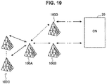
- FIG. 19 is a diagram for explaining technical features according to the present embodiment.
- each of a base station 100B (corresponding to a first base station) and a base station 100D (corresponding to a third base station) is connected to the core network 20, that is, to the backhaul.
- a base station 100A is connected to the backhaul using a wireless communication path to the base station 100B and relays connection to the backhaul of one or more base stations 100C (corresponding to a second base station) on the downstream side using a wireless communication path to the base stations 100C.
- the number of base stations 100B to which the base station 100A has already been connected is one is described here, a plurality of base stations 100B may be provided.
- the base station 100A provides, to the base station 100D, a notification of a connection request for connection to the backhaul using a wireless communication path to the base station 100D.
- the connection request may be transmitted using RRC signaling, for example.
- the connection request may include various kinds of information for assisting determination regarding connection availability that is made by the base station 100D. Hereinafter, an example thereof will be described.
- the connection request may include information related to the base stations 100C that are destinations to which the connection to the backhaul is provided.
- the information related to the base stations 100C included in the connection request may include a throughput that is provided to the base stations 100C and that relates to the connection to the backhaul using the wireless communication path to the base station 100C. That is, the connection request may include information indicating the throughput of the backhaul to be provided to the base stations 100C.
- the information that is included in the connection request and that relates to the base stations 100C may include the number of base stations 100C. That is, the connection request may include information indicating the number of base stations C on the downstream side to which the base station 100A provides the connection to the backhaul.
- the base station 100D can determined the connection availability on the basis of such information.
- the connection request may include information related to the base station 100B that is a source from which the connection to the backhaul is provided.
- the information that is included in the connection request and that relates to the base station 100B may include a throughput that relates to the connection to the backhaul that is provide from the base station 100B and uses the wireless communication path to the base station 100B. That is, the connection request may include information indicating the throughput of the backhaul that is provided from the base station 100B.
- the information that is included in the connection request and that relates to the base station 100B may include the number of base stations 100B. That is, the connection request may include information indicating the number of base stations B on the upstream that provide the connection to the backhaul to the base station 100A.
- the base station 100D can determined the connection availability on the basis of such information.
- Table 7 Example of information included in request for connection to backhaul Index Details Example of numerical value 1 The number of base stations on downstream to which base station provides backhaul 10 base stations 2 The number of base stations on upstream to which base station provides backhaul 2 base stations
- information of an index 1 is an example of information related to the base stations 100C that are the aforementioned destinations to which the connection to the backhaul is provided
- information of an index 2 is an example of information related to the base station 100B that is the aforementioned source from which the connection to the backhaul is provided.
- the base station 100D determines whether or not the request for connection to the backhaul using the wireless communication path to the base station 100A, which is received from the base station 100A (corresponding to a fourth base station) is to be permitted on the basis of the information that is included in the connection request and that relates to the base station 100B or the information that relates to the base stations 100C. For example, the base station 100D determines connection availability on the basis of whether or not the load imparted to the base station 100D itself is allowable, whether or not it is possible to maintain the throughput of the backhaul that is provided to the base station 100A and the base stations 100C, and the like. Then, the base station 100D replies with information indicating a result of the determination to the base station 100A.
- the information indicating the result of the determination may include information indicating a frequency resource (for example, a component carrier) to be used for the wireless connection in a case in which the connection is permitted.
- the information indicating the result of the determination may include information indicating a condition for the provision of the connection to the backhaul, for example, a condition that only three of ten base stations 100C on the downstream side of the base station 100A can be connected by way of the base station 100D.
- the information indicating the result of the determination may be transmitted using RRC signaling, for example.
- the base station 100A transmits an S1 setup request to the MME 21.
- the base station 100A may transmit the S 1 setup request via the plurality of routes.
- the base stations 100C may not transmit the S1 setup request. This is because the base stations 100C have already been connected to the backhaul by way of the base station 100A. It is a matter of course that the base stations 100C may transmit the S1 setup request.
- each base station 100 can prevent an excessive load and can be connected to the backhaul with an appropriate throughput.
- the base station 100A may be connected to the backhaul through a new route or may disconnect an existing route. Therefore, quality of the backhaul that the base station 100A provides may be improved or may be degraded.
- the base station 100A provides a notification of information indicating quality of the connection to the backhaul that is provided to the base stations 100C and that uses the wireless communication path to the base stations 100C (hereinafter, also referred to as provision quality information) to the base stations 100C. That is, the base station 100A provides, to the base station 100C, a notification of the provision quality information indicating the quality of the backhaul provided to the base station 100C.
- the base station 100A provides the notification of the provision quality information at a timing at which a change in the quality of the backhaul provided to the base stations 100C is recognized.
- a timing at which the connection route of the base station 100A to the backhaul increases or decreases is exemplified.
- the base stations 100C recognizes that the quality of the backhaul provided from the base station 100A has been improved or degraded with reference to the provision quality information.
- the base stations 100C can employ a measure, such as increasing/reducing the number of other base stations 100 on the downstream side that are destinations to which the connection to the backhaul is provided or reinforcing a backhaul line (connection to new backhaul and the like).
- provision quality information may be provided as a notification using RRC signaling or system information.
- the provision quality information may include various kinds of information. Hereinafter, an example thereof will be described.
- the provision quality information may include information indicating a throughput related to the connection to the backhaul using the wireless communication path to the base station 100C. That is, the information indicating quality of the connection to the backhaul may include information indicating the throughput of the backhaul that is provided to the base stations 100C.
- the provision quality information may include information indicating a delay time related to the connection to the backhaul using the wireless communication path to the base stations 100C. That is, the information indicating the quality of the connection to the backhaul may include information indicating a delay time of the backhaul that is provided to the base stations 100C.
- Table 8 Example of information included in provision quality information Index Details Examples of numerical value 1 Maximum value and minimum value of delay time 2000 ms, 150 ms 2 Capacity of backhaul line provided to base stations on downstream 2 Gbyte/second
- information of an index 1 is an example of the aforementioned information indicating the throughput of the backhaul
- information of an index 2 is an example of the aforementioned information indicating the delay time of the backhaul.
- the base stations 100C may transmit the provision quality information provided from the base station 100A to the terminal devices 200 connected to the base stations 100C.
- the base stations 100C may transmit the provision quality information of the base station 100A while including the provision quality information in the system information.
- the terminal devices 200 can attempt handover to other base stations 100 with satisfactory backhaul quality, for example.
- FIG. 20 is a sequence diagram illustrating an example of a flow of processing of establishing connection to new backhaul, which is executed by a base station 100A that has already been connected to backhaul in the cellular system 1 according to the present embodiment.
- the base station 100A that has already been connected to the backhaul a base station 100D that has already been connected to the backhaul, an MME 221, and an HSS 22 are involved in this sequence.
- the base station 100A transmits an S1 setup request including information related to a base stations 100C as a destination to which the connection to the backhaul is provided and information related to a base station 100B as sources from which the connection to the backhaul is provided to the base station 100D (Step S902).
- the base station 100D determines whether or not to provide the connection to the backhaul to the base station 100A on the basis of the information related to the base station 100C and the information related to the base station 100B received from the base station 100A (Step S904). In a case in which it is determined not to provide the connection to the backhaul (S904/NG), the base station 100D replies with an S1 setup rejection to the base station 100A (Step S906).
- the base station 100D transmits an S1 setup request to the MME 21 and the HSS 22 (Step S908), receives a replied S1 setup response (Step S910), and transfers the S1 setup response to the base station 100A (Step S912).
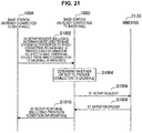
- FIG. 21 is a sequence diagram illustrating an example of a flow of processing of establishing connection to new backhaul, which is executed by a base station 100A that has already been connected to backhaul in the cellular system 1 according to the present embodiment.
- the base station 100A, a base station 100D, an MME 21, and an HSS 22 are involved in this sequence.
- the base station 100A transmits an S1 setup request including information related to a base station 100C as a destination to which the connection to the backhaul is provided and information related to a base station 100B as sources from which the connection to the backhaul is provided to the base station 100D (Step S1002).
- the base station 100D determines whether or not to provide the connection to the backhaul to the base station 100A on the basis of the information related to the base station 100C and the information related to the base station 100B received from the base station 100A (Step S1004). Then, the base station 100D transmits an S1 setup request to the MME 21 and the HSS 22 (Step S1006), receives a replied S1 setup response (Step S1008), and transfers the S1 setup response to the base station 100A (Step S1010).
- the base station 100D includes provision condition information indicating the number of base stations on the downstream side of the base station 100A for which the connection to the backhaul by way of the base station 100D itself is permitted, and the like in the S1 setup response to be transferred to the base station 100A.
- the base station 100 may be realized as any type of evolved node B (eNB), for example, a macro eNB, a small eNB, or the like.
- eNB evolved node B
- a small eNB may be an eNB that covers a smaller cell than a macro cell, such as a pico eNB, a micro eNB, or a home (femto) eNB.
- the base station 100 may be realized as another type of base station such as a node B or a base transceiver station (BTS).
- BTS base transceiver station
- the base station 100 may include a main body that controls wireless communication (also referred to as a base station device) and one or more remote radio heads (RRHs) disposed in a different place from the main body.
- a main body that controls wireless communication also referred to as a base station device
- RRHs remote radio heads
- various types of terminals to be described below may operate as the base station 100 by temporarily or semi-permanently executing the base station function.
- the terminal device 200 may be realized as, for example, a mobile terminal such as a smartphone, a tablet personal computer (PC), a notebook PC, a portable game terminal, a portable/dongle type mobile router, or a digital camera, or an in-vehicle terminal such as a car navigation device.
- the terminal device 200 may be realized as a terminal that performs machine-to-machine (M2M) communication (also referred to as a machine type communication (MTC) terminal).
- M2M machine-to-machine
- MTC machine type communication
- the terminal device 200 may be a wireless communication module mounted in such a terminal (for example, an integrated circuit module configured in one die).
- FIG. 22 is a block diagram illustrating a first example of a schematic configuration of an eNB to which the technology of the present disclosure may be applied.
- An eNB 800 includes one or more antennas 810 and a base station device 820. Each antenna 810 and the base station device 820 may be connected to each other via an RF cable.
- Each of the antennas 810 includes a single or multiple antenna elements (such as multiple antenna elements included in an MIMO antenna), and is used for the base station device 820 to transmit and receive radio signals.
- the eNB 800 may include the multiple antennas 810, as illustrated in FIG. 22 .
- the multiple antennas 810 may be compatible with multiple frequency bands used by the eNB 800.
- FIG. 22 illustrates the example in which the eNB 800 includes the multiple antennas 810, the eNB 800 may also include a single antenna 810.
- the base station device 820 includes a controller 821, a memory 822, a network interface 823, and a wireless communication interface 825.
- the controller 821 may be, for example, a CPU or a DSP, and operates various functions of a higher layer of the base station device 820. For example, the controller 821 generates a data packet from data in signals processed by the wireless communication interface 825, and transfers the generated packet via the network interface 823. The controller 821 may bundle data from multiple base band processors to generate the bundled packet, and transfer the generated bundled packet. The controller 821 may have logical functions of performing control such as radio resource control, radio bearer control, mobility management, admission control, and scheduling. The control may be performed in corporation with an eNB or a core network node in the vicinity.
- the memory 822 includes RAM and ROM, and stores a program that is executed by the controller 821, and various types of control data (such as a terminal list, transmission power data, and scheduling data).
- the network interface 823 is a communication interface for connecting the base station device 820 to a core network 824.
- the controller 821 may communicate with a core network node or another eNB via the network interface 823.
- the eNB 800 may be connected to a core network node or another eNB through a logical interface (e.g. S1 interface or X2 interface).
- the network interface 823 may also be a wired communication interface or a wireless communication interface for wireless backhaul. If the network interface 823 is a wireless communication interface, the network interface 823 may use a higher frequency band for wireless communication than a frequency band used by the wireless communication interface 825.
- the wireless communication interface 825 supports any cellular communication scheme such as Long Term Evolution (LTE) and LTE-Advanced, and provides radio connection to a terminal positioned in a cell of the eNB 800 via the antenna 810.
- the wireless communication interface 825 may typically include, for example, a baseband (BB) processor 826 and an RF circuit 827.
- the BB processor 826 may perform, for example, encoding/decoding, modulating/demodulating, and multiplexing/demultiplexing, and performs various types of signal processing of layers (such as L1, medium access control (MAC), radio link control (RLC), and a packet data convergence protocol (PDCP)).
- the BB processor 826 may have a part or all of the above-described logical functions instead of the controller 821.
- the BB processor 826 may be a memory that stores a communication control program, or a module that includes a processor and a related circuit configured to execute the program. Updating the program may allow the functions of the BB processor 826 to be changed.
- the module may be a card or a blade that is inserted into a slot of the base station device 820. Alternatively, the module may also be a chip that is mounted on the card or the blade.
- the RF circuit 827 may include, for example, a mixer, a filter, and an amplifier, and transmits and receives radio signals via the antenna 810.
- the wireless communication interface 825 may include the multiple BB processors 826, as illustrated in FIG. 22 .
- the multiple BB processors 826 may be compatible with multiple frequency bands used by the eNB 800.
- the wireless communication interface 825 may include the multiple RF circuits 827, as illustrated in FIG. 22 .
- the multiple RF circuits 827 may be compatible with multiple antenna elements.
- FIG. 22 illustrates the example in which the wireless communication interface 825 includes the multiple BB processors 826 and the multiple RF circuits 827, the wireless communication interface 825 may also include a single BB processor 826 or a single RF circuit 827.
- one or more constituent elements included in the processing unit 150 may be implemented by the wireless communication interface 825.
- the wireless communication interface 825 may be implemented by the controller 821.
- a module which includes a part (for example, the BB processor 826) or all of the wireless communication interface 825 and/or the controller 821 may be mounted in eNB 800, and the one or more constituent elements may be implemented by the module.
- the module may store a program for causing the processor to function as the one or more constituent elements (i.e., a program for causing the processor to execute operations of the one or more constituent elements) and may execute the program.
- the program for causing the processor to function as the one or more constituent elements may be installed in the eNB 800, and the wireless communication interface 825 (for example, the BB processor 826) and/or the controller 821 may execute the program.
- the eNB 800, the base station device 820, or the module may be provided as a device which includes the one or more constituent elements, and the program for causing the processor to function as the one or more constituent elements may be provided.
- a readable recording medium in which the program is recorded may be provided.
- the wireless communication unit 120 described above with reference to FIG. 7 may be mounted in the wireless communication interface 825 (for example, the RF circuit 827). Further, the antenna unit 110 may be mounted in the antenna 810. Further, the network communication unit 130 may be mounted in the controller 821 and/or the network interface 823. Further, the storage unit 140 may be mounted in the memory 822.
- FIG. 23 is a block diagram illustrating a second example of a schematic configuration of an eNB to which the technology of the present disclosure may be applied.
- An eNB 830 includes one or more antennas 840, a base station device 850, and an RRH 860. Each antenna 840 and the RRH 860 may be connected to each other via an RF cable. The base station device 850 and the RRH 860 may be connected to each other via a high speed line such as an optical fiber cable.
- Each of the antennas 840 includes a single or multiple antenna elements (such as multiple antenna elements included in an MIMO antenna), and is used for the RRH 860 to transmit and receive radio signals.
- the eNB 830 may include the multiple antennas 840, as illustrated in FIG. 23 .
- the multiple antennas 840 may be compatible with multiple frequency bands used by the eNB 830.
- FIG. 23 illustrates the example in which the eNB 830 includes the multiple antennas 840, the eNB 830 may also include a single antenna 840.
- the base station device 850 includes a controller 851, a memory 852, a network interface 853, a wireless communication interface 855, and a connection interface 857.
- the controller 851, the memory 852, and the network interface 853 are similar to the controller 821, the memory 822, and the network interface 823 described with reference to FIG. 22 .
- the wireless communication interface 855 supports any cellular communication scheme such as LTE and LTE-Advanced, and provides wireless communication to a terminal positioned in a sector corresponding to the RRH 860 via the RRH 860 and the antenna 840.
- the wireless communication interface 855 may typically include, for example, a BB processor 856.
- the BB processor 856 is similar to the BB processor 826 described with reference to FIG. 22 , except the BB processor 856 is connected to the RF circuit 864 of the RRH 860 via the connection interface 857.
- the wireless communication interface 855 may include the multiple BB processors 856, as illustrated in FIG. 23 .
- the multiple BB processors 856 may be compatible with multiple frequency bands used by the eNB 830.
- FIG. 23 illustrates the example in which the wireless communication interface 855 includes the multiple BB processors 856, the wireless communication interface 855 may also include a single BB processor 856.
- connection interface 857 is an interface for connecting the base station device 850 (wireless communication interface 855) to the RRH 860.
- the connection interface 857 may also be a communication module for communication in the above-described high speed line that connects the base station device 850 (wireless communication interface 855) to the RRH 860.
- the RRH 860 includes a connection interface 861 and a wireless communication interface 863.
- connection interface 861 is an interface for connecting the RRH 860 (wireless communication interface 863) to the base station device 850.
- the connection interface 861 may also be a communication module for communication in the above-described high speed line.
- the wireless communication interface 863 transmits and receives radio signals via the antenna 840.
- the wireless communication interface 863 may typically include, for example, the RF circuit 864.
- the RF circuit 864 may include, for example, a mixer, a filter, and an amplifier, and transmits and receives radio signals via the antenna 840.
- the wireless communication interface 863 may include multiple RF circuits 864, as illustrated in FIG. 23 .
- the multiple RF circuits 864 may support multiple antenna elements.
- FIG. 23 illustrates the example in which the wireless communication interface 863 includes the multiple RF circuits 864, the wireless communication interface 863 may also include a single RF circuit 864.
- one or more constituent elements included in the processing unit 150 may be implemented by the wireless communication interface 855 and/or the wireless communication interface 863.
- the controller 851 may be implemented by the BB processor 856 or all of the wireless communication interface 855 and/or the controller 851, and the one or more constituent elements may be implemented by the module.
- the module may store a program for causing the processor to function as the one or more constituent elements (i.e., a program for causing the processor to execute operations of the one or more constituent elements) and may execute the program.
- the program for causing the processor to function as the one or more constituent elements may be installed in the eNB 830, and the wireless communication interface 855 (for example, the BB processor 856) and/or the controller 851 may execute the program.
- the eNB 830, the base station device 850, or the module may be provided as a device which includes the one or more constituent elements, and the program for causing the processor to function as the one or more constituent elements may be provided.
- a readable recording medium in which the program is recorded may be provided.
- the wireless communication unit 120 described above with reference to FIG. 7 may be mounted in the wireless communication interface 863 (for example, the RF circuit 864). Further, the antenna unit 110 may be mounted on the antenna 840. Further, the network communication unit 130 may be mounted in the controller 851 and/or the network interface 853. Further, the storage unit 140 may be mounted in the memory 852.
- FIG. 24 is a block diagram illustrating an example of a schematic configuration of a smartphone 900 to which the technology of the present disclosure may be applied.
- the smartphone 900 includes a processor 901, a memory 902, a storage 903, an external connection interface 904, a camera 906, a sensor 907, a microphone 908, an input device 909, a display device 910, a speaker 911, a wireless communication interface 912, one or more antenna switches 915, one or more antennas 916, a bus 917, a battery 918, and an auxiliary controller 919.
- the processor 901 may be, for example, a CPU or a system on a chip (SoC), and controls functions of an application layer and another layer of the smartphone 900.
- the memory 902 includes RAM and ROM, and stores a program that is executed by the processor 901, and data.
- the storage 903 may include a storage medium such as a semiconductor memory and a hard disk.
- the external connection interface 904 is an interface for connecting an external device such as a memory card and a universal serial bus (USB) device to the smartphone 900.
- USB universal serial bus
- the camera 906 includes an image sensor such as a charge coupled device (CCD) and a complementary metal oxide semiconductor (CMOS), and generates a captured image.
- the sensor 907 may include a group of sensors such as a measurement sensor, a gyro sensor, a geomagnetic sensor, and an acceleration sensor.
- the microphone 908 converts sounds that are input to the smartphone 900 to audio signals.
- the input device 909 includes, for example, a touch sensor configured to detect touch onto a screen of the display device 910, a keypad, a keyboard, a button, or a switch, and receives an operation or an information input from a user.
- the display device 910 includes a screen such as a liquid crystal display (LCD) and an organic light-emitting diode (OLED) display, and displays an output image of the smartphone 900.
- the speaker 911 converts audio signals that are output from the smartphone 900 to sounds.
- the wireless communication interface 912 supports any cellular communication scheme such as LTE and LTE-Advanced, and performs wireless communication.
- the wireless communication interface 912 may typically include, for example, a BB processor 913 and an RF circuit 914.
- the BB processor 913 may perform, for example, encoding/decoding, modulating/demodulating, and multiplexing/demultiplexing, and performs various types of signal processing for wireless communication.
- the RF circuit 914 may include, for example, a mixer, a filter, and an amplifier, and transmits and receives radio signals via the antenna 916.
- the wireless communication interface 912 may also be a one chip module that has the BB processor 913 and the RF circuit 914 integrated thereon.
- the wireless communication interface 912 may include the multiple BB processors 913 and the multiple RF circuits 914, as illustrated in FIG. 24 .
- FIG. 24 illustrates the example in which the wireless communication interface 912 includes the multiple BB processors 913 and the multiple RF circuits 914, the wireless communication interface 912 may also include a single BB processor 913 or a single RF circuit 914.
- the wireless communication interface 912 may support another type of wireless communication scheme such as a short-distance wireless communication scheme, a near field communication scheme, and a wireless local area network (LAN) scheme.
- the wireless communication interface 912 may include the BB processor 913 and the RF circuit 914 for each wireless communication scheme.
- Each of the antenna switches 915 switches connection destinations of the antennas 916 among multiple circuits (such as circuits for different wireless communication schemes) included in the wireless communication interface 912.
- Each of the antennas 916 includes a single or multiple antenna elements (such as multiple antenna elements included in an MIMO antenna), and is used for the wireless communication interface 912 to transmit and receive radio signals.
- the smartphone 900 may include the multiple antennas 916, as illustrated in FIG. 24 . Although FIG. 24 illustrates the example in which the smartphone 900 includes the multiple antennas 916, the smartphone 900 may also include a single antenna 916.
- the smartphone 900 may include the antenna 916 for each wireless communication scheme.
- the antenna switches 915 may be omitted from the configuration of the smartphone 900.
- the bus 917 connects the processor 901, the memory 902, the storage 903, the external connection interface 904, the camera 906, the sensor 907, the microphone 908, the input device 909, the display device 910, the speaker 911, the wireless communication interface 912, and the auxiliary controller 919 to each other.
- the battery 918 supplies power to blocks of the smartphone 900 illustrated in FIG. 24 via feeder lines, which are partially shown as dashed lines in the figure.
- the auxiliary controller 919 operates a minimum necessary function of the smartphone 900, for example, in a sleep mode.
- one or more constituent elements included in the processing unit 240 may be implemented by the wireless communication interface 912.
- the processor 901 or the auxiliary controller 919 may be implemented by the processor 901 or the auxiliary controller 919.
- the module may store a program for causing the processor to function as the one or more constituent elements (i.e., a program for causing the processor to execute operations of the one or more constituent elements) and may execute the program.
- the program for causing the processor to function as the one or more constituent elements may be installed in the smartphone 900, and the wireless communication interface 912 (for example, the BB processor 913), the processor 901 and/or the auxiliary controller 919 may execute the program.
- the smartphone 900 or the module may be provided as a device which includes the one or more constituent elements, and the program for causing the processor to function as the one or more constituent elements may be provided.
- a readable recording medium in which the program is recorded may be provided.
- the wireless communication unit 220 described above with reference to FIG. 8 may be mounted in the wireless communication interface 912 (for example, the RF circuit 914). Further, the antenna unit 210 may be mounted on the antenna 916. Further, the storage unit 230 may be mounted in the memory 902.
- FIG. 25 is a block diagram illustrating an example of a schematic configuration of a car navigation device 920 to which the technology of the present disclosure may be applied.
- the car navigation device 920 includes a processor 921, a memory 922, a global positioning system (GPS) module 924, a sensor 925, a data interface 926, a content player 927, a storage medium interface 928, an input device 929, a display device 930, a speaker 931, a wireless communication interface 933, one or more antenna switches 936, one or more antennas 937, and a battery 938.
- GPS global positioning system
- the processor 921 may be, for example, a CPU or a SoC, and controls a navigation function and another function of the car navigation device 920.
- the memory 922 includes RAM and ROM, and stores a program that is executed by the processor 921, and data.
- the GPS module 924 uses GPS signals received from a GPS satellite to measure a position (such as latitude, longitude, and altitude) of the car navigation device 920.
- the sensor 925 may include a group of sensors such as a gyro sensor, a geomagnetic sensor, and a barometric sensor.
- the data interface 926 is connected to, for example, an in-vehicle network 941 via a terminal that is not shown, and acquires data generated by the vehicle, such as vehicle speed data.
- the content player 927 reproduces content stored in a storage medium (such as a CD and a DVD) that is inserted into the storage medium interface 928.
- the input device 929 includes, for example, a touch sensor configured to detect touch onto a screen of the display device 930, a button, or a switch, and receives an operation or an information input from a user.
- the display device 930 includes a screen such as an LCD or an OLED display, and displays an image of the navigation function or content that is reproduced.
- the speaker 931 outputs sounds of the navigation function or the content that is reproduced.
- the wireless communication interface 933 supports any cellular communication scheme such as LET and LTE-Advanced, and performs wireless communication.
- the wireless communication interface 933 may typically include, for example, a BB processor 934 and an RF circuit 935.
- the BB processor 934 may perform, for example, encoding/decoding, modulating/demodulating, and multiplexing/demultiplexing, and performs various types of signal processing for wireless communication.
- the RF circuit 935 may include, for example, a mixer, a filter, and an amplifier, and transmits and receives radio signals via the antenna 937.
- the wireless communication interface 933 may be a one chip module having the BB processor 934 and the RF circuit 935 integrated thereon.
- the wireless communication interface 933 may include the multiple BB processors 934 and the multiple RF circuits 935, as illustrated in FIG. 25 .
- FIG. 25 illustrates the example in which the wireless communication interface 933 includes the multiple BB processors 934 and the multiple RF circuits 935, the wireless communication interface 933 may also include a single BB processor 934 or a single RF circuit 935.
- the wireless communication interface 933 may support another type of wireless communication scheme such as a short-distance wireless communication scheme, a near field communication scheme, and a wireless LAN scheme.
- the wireless communication interface 933 may include the BB processor 934 and the RF circuit 935 for each wireless communication scheme.
- Each of the antenna switches 936 switches connection destinations of the antennas 937 among multiple circuits (such as circuits for different wireless communication schemes) included in the wireless communication interface 933.
- Each of the antennas 937 includes a single or multiple antenna elements (such as multiple antenna elements included in an MIMO antenna), and is used for the wireless communication interface 933 to transmit and receive radio signals.
- the car navigation device 920 may include the multiple antennas 937, as illustrated in FIG. 25 . Although FIG. 25 illustrates the example in which the car navigation device 920 includes the multiple antennas 937, the car navigation device 920 may also include a single antenna 937.
- the car navigation device 920 may include the antenna 937 for each wireless communication scheme.
- the antenna switches 936 may be omitted from the configuration of the car navigation device 920.
- the battery 938 supplies power to blocks of the car navigation device 920 illustrated in FIG. 25 via feeder lines that are partially shown as dashed lines in the figure.
- the battery 938 accumulates power supplied from the vehicle.
- one or more constituent elements included in the processing unit 240 may be implemented by the wireless communication interface 933.
- the processor 921 may be implemented by the processor 921.
- a module which includes a part (for example, the BB processor 934) or all of the wireless communication interface 933 and/or the processor 921 may be mounted in the car navigation device 920, and the one or more constituent elements may be implemented by the module.
- the module may store a program for causing the processor to function as the one or more constituent elements (i.e., a program for causing the processor to execute operations of the one or more constituent elements) and may execute the program.
- the program for causing the processor to function as the one or more constituent elements may be installed in the car navigation device 920, and the wireless communication interface 933 (for example, the BB processor 934) and/or the processor 921 may execute the program.
- the car navigation device 920 or the module may be provided as a device which includes the one or more constituent elements, and the program for causing the processor to function as the one or more constituent elements may be provided.
- a readable recording medium in which the program is recorded may be provided.
- the wireless communication unit 220 described above with reference to FIG. 8 may be mounted in the wireless communication interface 933 (for example, the RF circuit 935). Further, the antenna unit 210 may be mounted on the antenna 937. Further, the storage unit 230 may be mounted in the memory 922.
- the technology of the present disclosure may also be realized as an in-vehicle system (or a vehicle) 940 including one or more blocks of the car navigation device 920, the in-vehicle network 941, and a vehicle module 942.
- the vehicle module 942 generates vehicle data such as vehicle speed, engine speed, and trouble information, and outputs the generated data to the in-vehicle network 941.
- the base station 100 is connected to the S1-MME interface and the S1-U interface.
- Both the communication route in which the S1-MME interface is formed and the communication route in which the S1-U interface is formed include a wireless communication path formed between the first base station and the second base station. It is possible to use the common wired communication path among a plurality of interfaces in this manner and thereby to flexibly construct the backhaul including the wireless communication paths.
- the base station 100 is connected to the backhaul including the S1-MME interface using the wireless communication paths to other base stations 100 and provides a notification of the information related to the connected backhaul while including the information in the system information.
- the terminal devices 200 or other base stations 100 that are connected to or attempt to be connected to the base station 100 can appropriately make various kinds of determination such as availability of connection or necessity of switching in relation to the communication with the base station 100.
- the base station 100 performs the authentication processing for establishing connection to the backhaul using the wireless communication paths to other base stations 100 that are connected to the backhaul. In this manner, since only the permitted base stations 100 can be connected to the backhaul, it is possible to curb unnecessary consumption of the backhaul including the wireless communication paths.
- the base station 100 is connected to the backhaul using a wireless communication path to the first base station that is connected to the backhaul, relays connection of one or more second base stations on the downstream side to the backhaul using a wireless communication path to the second base station, and provides a notification of a connection request for the connection to the backhaul to a third base station using a wireless communication path to the third base station.
- the third base station can appropriately predict a load in a case in which the connection request is permitted, and it is possible to avoid a situation in which a significantly load is imparted due to permission.
- the terminal device 200 performs processing based on information that is provided as a notification from the base station 100 connected to the backhaul including the S1-MME interface using the wireless communication paths to other base stations 100, that is included in the system information, and that relates to the backhaul. In this manner, the terminal devices 200 can perform appropriate processing such as an attempt of handover in accordance with quality or the like of the backhaul to which the base station 100 is connected.
- the base station 100 may provide a notification of information related to the X2 interface while including the information in the system information.
- present technology may also be configured as below.
Landscapes
- Engineering & Computer Science (AREA)
- Computer Networks & Wireless Communication (AREA)
- Signal Processing (AREA)
- Quality & Reliability (AREA)
- Mobile Radio Communication Systems (AREA)
Applications Claiming Priority (2)
| Application Number | Priority Date | Filing Date | Title |
|---|---|---|---|
| JP2016227052A JP6953706B2 (ja) | 2016-11-22 | 2016-11-22 | 基地局 |
| PCT/JP2017/037480 WO2018096839A1 (ja) | 2016-11-22 | 2017-10-17 | 基地局及び端末装置 |
Publications (3)
| Publication Number | Publication Date |
|---|---|
| EP3547794A1 true EP3547794A1 (de) | 2019-10-02 |
| EP3547794A4 EP3547794A4 (de) | 2019-12-04 |
| EP3547794B1 EP3547794B1 (de) | 2023-08-16 |
Family
ID=62195015
Family Applications (1)
| Application Number | Title | Priority Date | Filing Date |
|---|---|---|---|
| EP17873179.0A Active EP3547794B1 (de) | 2016-11-22 | 2017-10-17 | Basisstation und endgerätevorrichtung |
Country Status (6)
| Country | Link |
|---|---|
| US (1) | US11172539B2 (de) |
| EP (1) | EP3547794B1 (de) |
| JP (1) | JP6953706B2 (de) |
| CN (1) | CN109937610B (de) |
| ES (1) | ES2955837T3 (de) |
| WO (1) | WO2018096839A1 (de) |
Families Citing this family (13)
| Publication number | Priority date | Publication date | Assignee | Title |
|---|---|---|---|---|
| CN109257609B (zh) * | 2018-09-30 | 2021-04-23 | Oppo广东移动通信有限公司 | 数据处理方法及装置、电子设备及存储介质 |
| WO2020109178A1 (en) | 2018-11-30 | 2020-06-04 | Sony Mobile Communications Inc. | Spectrum access restriction and re-routing of data |
| EP3927018B1 (de) | 2019-02-15 | 2026-04-01 | Sony Group Corporation | Informationsverarbeitungsvorrichtung, informationsverarbeitungsverfahren und informationsverarbeitungsprogramm |
| JP7311991B2 (ja) * | 2019-03-26 | 2023-07-20 | キヤノン株式会社 | 通信装置、通信装置の制御方法、プログラム |
| JP7340941B2 (ja) | 2019-03-26 | 2023-09-08 | キヤノン株式会社 | 通信装置、制御方法、及びプログラム |
| EP3952455B1 (de) * | 2019-03-29 | 2025-05-21 | Honda Motor Co., Ltd. | Basisstation, kommunikationssystem, kommunikationsverfahren und programm |
| CN114073117B (zh) * | 2019-03-29 | 2024-05-14 | 本田技研工业株式会社 | 终端装置、通信系统、通信方法以及存储介质 |
| CN113574933B (zh) * | 2019-03-29 | 2023-12-12 | 本田技研工业株式会社 | 终端装置、通信系统、通信方法以及存储介质 |
| US10749551B1 (en) * | 2019-05-31 | 2020-08-18 | Cox Communications, Inc. | Systems and methods for extended spectrum amplifiers |
| WO2021033268A1 (ja) * | 2019-08-20 | 2021-02-25 | 富士通株式会社 | 基地局装置、中継装置、及び通信システム |
| JP7390148B2 (ja) * | 2019-09-30 | 2023-12-01 | パナソニックホールディングス株式会社 | ネットワーク制御装置、ネットワーク制御システム、及びネットワーク制御方法 |
| US20230397083A1 (en) * | 2020-10-29 | 2023-12-07 | Panasonic Holdings Corporation | Network control device, network control system, network control method, and wireless network system construction method |
| CN112654062B (zh) * | 2020-12-04 | 2024-05-14 | 京信网络系统股份有限公司 | 一种时延确定方法、装置、设备及介质 |
Family Cites Families (19)
| Publication number | Priority date | Publication date | Assignee | Title |
|---|---|---|---|---|
| JP4582098B2 (ja) | 2003-02-03 | 2010-11-17 | ソニー株式会社 | 無線通信システム、通信装置、通信方法及びプログラム |
| US8902805B2 (en) * | 2008-10-24 | 2014-12-02 | Qualcomm Incorporated | Cell relay packet routing |
| EP2416530B1 (de) * | 2009-03-30 | 2015-05-06 | Huawei Technologies Co., Ltd. | Verfahren, netzwerksystem und einrichtung zur realisierung von datenneuübertragung |
| TWI426807B (zh) | 2009-06-23 | 2014-02-11 | Inst Information Industry | 基地台、中繼台及其後端控制通訊方法 |
| CN101932123B (zh) | 2009-06-23 | 2013-05-08 | 财团法人资讯工业策进会 | 中继台及其后端连线方法 |
| KR101636582B1 (ko) * | 2009-06-24 | 2016-07-06 | 엘지전자 주식회사 | 무선 통신 시스템에서 rb 설정 방법 및 장치 |
| JP2013080986A (ja) * | 2010-02-12 | 2013-05-02 | Mitsubishi Electric Corp | 移動体通信システム |
| JP5795809B2 (ja) * | 2011-02-04 | 2015-10-14 | テレフオンアクチーボラゲット エル エム エリクソン(パブル) | バックホール選択をサポートする方法及び装置 |
| US20120250601A1 (en) | 2011-03-28 | 2012-10-04 | Hyung-Nam Choi | Communication terminal, method for exchanging data, communication device and method for establishing a communication connection |
| RU2014118578A (ru) * | 2011-10-10 | 2015-11-20 | Телефонактиеболагет Л М Эрикссон (Пабл) | Способ и устройство для передачи обслуживания мобильных ретрансляторов |
| EP2793500B1 (de) * | 2011-11-25 | 2017-09-13 | Kyocera Corporation | Kommunikationssteuerverfahren und relaisstation |
| CN103988546A (zh) * | 2011-12-08 | 2014-08-13 | 交互数字专利控股公司 | 高速双波段蜂窝通信 |
| EP2795964B1 (de) * | 2011-12-19 | 2019-02-27 | Telefonaktiebolaget LM Ericsson (publ) | Netzwerkknoten und verfahren in einem netzwerkknoten |
| US9161357B2 (en) * | 2012-02-01 | 2015-10-13 | Qualcomm Incorporated | Method and apparatus for white space operation by a mobile entity |
| CN105075388B (zh) * | 2013-03-29 | 2019-07-16 | 英特尔Ip公司 | 用于辅助双连通性的技术 |
| WO2016140403A1 (ko) * | 2015-03-05 | 2016-09-09 | 엘지전자(주) | 무선 통신 시스템에서 단말의 rrc 연결 방법 및 장치 |
| US10148340B1 (en) * | 2016-03-30 | 2018-12-04 | Sprint Communications Company L.P. | Multi-core communication system to serve wireless relays and user equipment |
| WO2017193056A1 (en) * | 2016-05-05 | 2017-11-09 | Ntt Docomo, Inc. | Mechanism and procedure of base station selection based on uplink pilot and distributed user-proximity detection |
| JP6822479B2 (ja) * | 2016-09-23 | 2021-01-27 | 日本電気株式会社 | 情報処理装置、通信方法および通信プログラム、通信システム、IoTデバイス並びに基地局 |
-
2016
- 2016-11-22 JP JP2016227052A patent/JP6953706B2/ja active Active
-
2017
- 2017-10-17 WO PCT/JP2017/037480 patent/WO2018096839A1/ja not_active Ceased
- 2017-10-17 CN CN201780070513.1A patent/CN109937610B/zh active Active
- 2017-10-17 US US16/349,631 patent/US11172539B2/en active Active
- 2017-10-17 ES ES17873179T patent/ES2955837T3/es active Active
- 2017-10-17 EP EP17873179.0A patent/EP3547794B1/de active Active
Also Published As
| Publication number | Publication date |
|---|---|
| CN109937610B (zh) | 2022-09-27 |
| JP6953706B2 (ja) | 2021-10-27 |
| US20190349950A1 (en) | 2019-11-14 |
| JP2018085606A (ja) | 2018-05-31 |
| EP3547794A4 (de) | 2019-12-04 |
| EP3547794B1 (de) | 2023-08-16 |
| CN109937610A (zh) | 2019-06-25 |
| ES2955837T3 (es) | 2023-12-07 |
| WO2018096839A1 (ja) | 2018-05-31 |
| US11172539B2 (en) | 2021-11-09 |
Similar Documents
| Publication | Publication Date | Title |
|---|---|---|
| EP3547794B1 (de) | Basisstation und endgerätevorrichtung | |
| EP3554137B1 (de) | Endgerätevorrichtung, verfahren und aufzeichnungsmedium | |
| CN105830530B (zh) | 无线电通信装置、通信控制装置、无线电通信方法和通信控制方法 | |
| EP3579614A1 (de) | Relaiskommunikationsvorrichtung, basisstation, verfahren und aufzeichnungsmedium | |
| EP3313106B1 (de) | System und verfahren zur verwaltung von endgeräte | |
| US11139887B2 (en) | System and method for radio link sharing | |
| US12328627B2 (en) | Electronic apparatus, radio communication method, and computer-readable storage medium | |
| CN106686674A (zh) | 无线通信系统中的电子设备和无线通信方法 | |
| EP3592042A1 (de) | Endgerätevorrichtung, basisstation, steuerungsvorrichtung, verfahren und aufzeichnungsmedium | |
| EP3209045B1 (de) | Kommunikationssteuerungsvorrichtung, basisstation, und kommunikationssteuerungsverfahren | |
| CN109155950A (zh) | 电子设备及由电子设备执行的方法 | |
| AU2017262128A1 (en) | Electronic apparatus, information processing device and information processing method | |
| US20210211943A1 (en) | Communication control device and communication control method for controlling frequency channel sharing and handover arrangements between primary system and secondary system | |
| AU2015251884B2 (en) | Apparatus | |
| EP3439424A1 (de) | Relaisvorrichtung, endgerätevorrichtung und kommunikationsverfahren | |
| WO2021164675A1 (zh) | 电子设备、无线通信方法和计算机可读存储介质 | |
| EP3163973A1 (de) | Vorrichtung, verfahren und programm | |
| CN113994724B (zh) | 电子设备、无线通信方法和计算机可读存储介质 | |
| WO2025185520A1 (zh) | 用于v2x的业务协同和感知数据共享 | |
| WO2025094954A1 (ja) | 通信方法、ユーザ装置、及びネットワークノード | |
| WO2025167247A1 (zh) | 无线通信方法及通信设备 | |
| WO2026090065A1 (en) | Signalling reduction for fixed wireless access devices | |
| WO2023207687A1 (zh) | 用于快速切换通信模式的设备、方法和介质 | |
| WO2017094360A1 (ja) | 装置、方法及びプログラム |
Legal Events
| Date | Code | Title | Description |
|---|---|---|---|
| STAA | Information on the status of an ep patent application or granted ep patent |
Free format text: STATUS: THE INTERNATIONAL PUBLICATION HAS BEEN MADE |
|
| PUAI | Public reference made under article 153(3) epc to a published international application that has entered the european phase |
Free format text: ORIGINAL CODE: 0009012 |
|
| STAA | Information on the status of an ep patent application or granted ep patent |
Free format text: STATUS: REQUEST FOR EXAMINATION WAS MADE |
|
| 17P | Request for examination filed |
Effective date: 20190514 |
|
| AK | Designated contracting states |
Kind code of ref document: A1 Designated state(s): AL AT BE BG CH CY CZ DE DK EE ES FI FR GB GR HR HU IE IS IT LI LT LU LV MC MK MT NL NO PL PT RO RS SE SI SK SM TR |
|
| AX | Request for extension of the european patent |
Extension state: BA ME |
|
| A4 | Supplementary search report drawn up and despatched |
Effective date: 20191104 |
|
| RIC1 | Information provided on ipc code assigned before grant |
Ipc: H04W 84/04 20090101ALI20191028BHEP Ipc: H04W 12/04 20090101ALI20191028BHEP Ipc: H04W 84/18 20090101ALI20191028BHEP Ipc: H04B 7/26 20060101ALI20191028BHEP Ipc: H04W 16/26 20090101ALI20191028BHEP Ipc: H04W 92/14 20090101AFI20191028BHEP |
|
| DAV | Request for validation of the european patent (deleted) | ||
| DAX | Request for extension of the european patent (deleted) | ||
| STAA | Information on the status of an ep patent application or granted ep patent |
Free format text: STATUS: EXAMINATION IS IN PROGRESS |
|
| 17Q | First examination report despatched |
Effective date: 20201215 |
|
| RAP3 | Party data changed (applicant data changed or rights of an application transferred) |
Owner name: SONY GROUP CORPORATION |
|
| GRAP | Despatch of communication of intention to grant a patent |
Free format text: ORIGINAL CODE: EPIDOSNIGR1 |
|
| STAA | Information on the status of an ep patent application or granted ep patent |
Free format text: STATUS: GRANT OF PATENT IS INTENDED |
|
| INTG | Intention to grant announced |
Effective date: 20230324 |
|
| GRAS | Grant fee paid |
Free format text: ORIGINAL CODE: EPIDOSNIGR3 |
|
| GRAA | (expected) grant |
Free format text: ORIGINAL CODE: 0009210 |
|
| STAA | Information on the status of an ep patent application or granted ep patent |
Free format text: STATUS: THE PATENT HAS BEEN GRANTED |
|
| AK | Designated contracting states |
Kind code of ref document: B1 Designated state(s): AL AT BE BG CH CY CZ DE DK EE ES FI FR GB GR HR HU IE IS IT LI LT LU LV MC MK MT NL NO PL PT RO RS SE SI SK SM TR |
|
| REG | Reference to a national code |
Ref country code: GB Ref legal event code: FG4D |
|
| REG | Reference to a national code |
Ref country code: CH Ref legal event code: EP |
|
| REG | Reference to a national code |
Ref country code: DE Ref legal event code: R096 Ref document number: 602017072922 Country of ref document: DE |
|
| REG | Reference to a national code |
Ref country code: IE Ref legal event code: FG4D |
|
| REG | Reference to a national code |
Ref country code: NL Ref legal event code: FP |
|
| REG | Reference to a national code |
Ref country code: ES Ref legal event code: FG2A Ref document number: 2955837 Country of ref document: ES Kind code of ref document: T3 Effective date: 20231207 |
|
| REG | Reference to a national code |
Ref country code: LT Ref legal event code: MG9D |
|
| REG | Reference to a national code |
Ref country code: AT Ref legal event code: MK05 Ref document number: 1601373 Country of ref document: AT Kind code of ref document: T Effective date: 20230816 |
|
| PG25 | Lapsed in a contracting state [announced via postgrant information from national office to epo] |
Ref country code: GR Free format text: LAPSE BECAUSE OF FAILURE TO SUBMIT A TRANSLATION OF THE DESCRIPTION OR TO PAY THE FEE WITHIN THE PRESCRIBED TIME-LIMIT Effective date: 20231117 |
|
| PG25 | Lapsed in a contracting state [announced via postgrant information from national office to epo] |
Ref country code: IS Free format text: LAPSE BECAUSE OF FAILURE TO SUBMIT A TRANSLATION OF THE DESCRIPTION OR TO PAY THE FEE WITHIN THE PRESCRIBED TIME-LIMIT Effective date: 20231216 |
|
| PG25 | Lapsed in a contracting state [announced via postgrant information from national office to epo] |
Ref country code: SE Free format text: LAPSE BECAUSE OF FAILURE TO SUBMIT A TRANSLATION OF THE DESCRIPTION OR TO PAY THE FEE WITHIN THE PRESCRIBED TIME-LIMIT Effective date: 20230816 Ref country code: RS Free format text: LAPSE BECAUSE OF FAILURE TO SUBMIT A TRANSLATION OF THE DESCRIPTION OR TO PAY THE FEE WITHIN THE PRESCRIBED TIME-LIMIT Effective date: 20230816 Ref country code: PT Free format text: LAPSE BECAUSE OF FAILURE TO SUBMIT A TRANSLATION OF THE DESCRIPTION OR TO PAY THE FEE WITHIN THE PRESCRIBED TIME-LIMIT Effective date: 20231218 Ref country code: NO Free format text: LAPSE BECAUSE OF FAILURE TO SUBMIT A TRANSLATION OF THE DESCRIPTION OR TO PAY THE FEE WITHIN THE PRESCRIBED TIME-LIMIT Effective date: 20231116 Ref country code: LV Free format text: LAPSE BECAUSE OF FAILURE TO SUBMIT A TRANSLATION OF THE DESCRIPTION OR TO PAY THE FEE WITHIN THE PRESCRIBED TIME-LIMIT Effective date: 20230816 Ref country code: LT Free format text: LAPSE BECAUSE OF FAILURE TO SUBMIT A TRANSLATION OF THE DESCRIPTION OR TO PAY THE FEE WITHIN THE PRESCRIBED TIME-LIMIT Effective date: 20230816 Ref country code: IS Free format text: LAPSE BECAUSE OF FAILURE TO SUBMIT A TRANSLATION OF THE DESCRIPTION OR TO PAY THE FEE WITHIN THE PRESCRIBED TIME-LIMIT Effective date: 20231216 Ref country code: HR Free format text: LAPSE BECAUSE OF FAILURE TO SUBMIT A TRANSLATION OF THE DESCRIPTION OR TO PAY THE FEE WITHIN THE PRESCRIBED TIME-LIMIT Effective date: 20230816 Ref country code: GR Free format text: LAPSE BECAUSE OF FAILURE TO SUBMIT A TRANSLATION OF THE DESCRIPTION OR TO PAY THE FEE WITHIN THE PRESCRIBED TIME-LIMIT Effective date: 20231117 Ref country code: FI Free format text: LAPSE BECAUSE OF FAILURE TO SUBMIT A TRANSLATION OF THE DESCRIPTION OR TO PAY THE FEE WITHIN THE PRESCRIBED TIME-LIMIT Effective date: 20230816 Ref country code: AT Free format text: LAPSE BECAUSE OF FAILURE TO SUBMIT A TRANSLATION OF THE DESCRIPTION OR TO PAY THE FEE WITHIN THE PRESCRIBED TIME-LIMIT Effective date: 20230816 |
|
| PG25 | Lapsed in a contracting state [announced via postgrant information from national office to epo] |
Ref country code: PL Free format text: LAPSE BECAUSE OF FAILURE TO SUBMIT A TRANSLATION OF THE DESCRIPTION OR TO PAY THE FEE WITHIN THE PRESCRIBED TIME-LIMIT Effective date: 20230816 |
|
| PG25 | Lapsed in a contracting state [announced via postgrant information from national office to epo] |
Ref country code: SM Free format text: LAPSE BECAUSE OF FAILURE TO SUBMIT A TRANSLATION OF THE DESCRIPTION OR TO PAY THE FEE WITHIN THE PRESCRIBED TIME-LIMIT Effective date: 20230816 Ref country code: RO Free format text: LAPSE BECAUSE OF FAILURE TO SUBMIT A TRANSLATION OF THE DESCRIPTION OR TO PAY THE FEE WITHIN THE PRESCRIBED TIME-LIMIT Effective date: 20230816 Ref country code: EE Free format text: LAPSE BECAUSE OF FAILURE TO SUBMIT A TRANSLATION OF THE DESCRIPTION OR TO PAY THE FEE WITHIN THE PRESCRIBED TIME-LIMIT Effective date: 20230816 Ref country code: DK Free format text: LAPSE BECAUSE OF FAILURE TO SUBMIT A TRANSLATION OF THE DESCRIPTION OR TO PAY THE FEE WITHIN THE PRESCRIBED TIME-LIMIT Effective date: 20230816 Ref country code: CZ Free format text: LAPSE BECAUSE OF FAILURE TO SUBMIT A TRANSLATION OF THE DESCRIPTION OR TO PAY THE FEE WITHIN THE PRESCRIBED TIME-LIMIT Effective date: 20230816 Ref country code: SK Free format text: LAPSE BECAUSE OF FAILURE TO SUBMIT A TRANSLATION OF THE DESCRIPTION OR TO PAY THE FEE WITHIN THE PRESCRIBED TIME-LIMIT Effective date: 20230816 |
|
| REG | Reference to a national code |
Ref country code: DE Ref legal event code: R097 Ref document number: 602017072922 Country of ref document: DE |
|
| PG25 | Lapsed in a contracting state [announced via postgrant information from national office to epo] |
Ref country code: MC Free format text: LAPSE BECAUSE OF FAILURE TO SUBMIT A TRANSLATION OF THE DESCRIPTION OR TO PAY THE FEE WITHIN THE PRESCRIBED TIME-LIMIT Effective date: 20230816 |
|
| REG | Reference to a national code |
Ref country code: CH Ref legal event code: PL |
|
| REG | Reference to a national code |
Ref country code: BE Ref legal event code: MM Effective date: 20231031 |
|
| PG25 | Lapsed in a contracting state [announced via postgrant information from national office to epo] |
Ref country code: LU Free format text: LAPSE BECAUSE OF NON-PAYMENT OF DUE FEES Effective date: 20231017 |
|
| PLBE | No opposition filed within time limit |
Free format text: ORIGINAL CODE: 0009261 |
|
| STAA | Information on the status of an ep patent application or granted ep patent |
Free format text: STATUS: NO OPPOSITION FILED WITHIN TIME LIMIT |
|
| PG25 | Lapsed in a contracting state [announced via postgrant information from national office to epo] |
Ref country code: LU Free format text: LAPSE BECAUSE OF NON-PAYMENT OF DUE FEES Effective date: 20231017 |
|
| PG25 | Lapsed in a contracting state [announced via postgrant information from national office to epo] |
Ref country code: CH Free format text: LAPSE BECAUSE OF NON-PAYMENT OF DUE FEES Effective date: 20231031 |
|
| 26N | No opposition filed |
Effective date: 20240517 |
|
| PG25 | Lapsed in a contracting state [announced via postgrant information from national office to epo] |
Ref country code: IT Free format text: LAPSE BECAUSE OF FAILURE TO SUBMIT A TRANSLATION OF THE DESCRIPTION OR TO PAY THE FEE WITHIN THE PRESCRIBED TIME-LIMIT Effective date: 20230816 Ref country code: CH Free format text: LAPSE BECAUSE OF NON-PAYMENT OF DUE FEES Effective date: 20231031 Ref country code: SI Free format text: LAPSE BECAUSE OF FAILURE TO SUBMIT A TRANSLATION OF THE DESCRIPTION OR TO PAY THE FEE WITHIN THE PRESCRIBED TIME-LIMIT Effective date: 20230816 |
|
| PG25 | Lapsed in a contracting state [announced via postgrant information from national office to epo] |
Ref country code: BE Free format text: LAPSE BECAUSE OF NON-PAYMENT OF DUE FEES Effective date: 20231031 |
|
| PG25 | Lapsed in a contracting state [announced via postgrant information from national office to epo] |
Ref country code: IE Free format text: LAPSE BECAUSE OF NON-PAYMENT OF DUE FEES Effective date: 20231017 |
|
| PGFP | Annual fee paid to national office [announced via postgrant information from national office to epo] |
Ref country code: GB Payment date: 20240919 Year of fee payment: 8 |
|
| PGFP | Annual fee paid to national office [announced via postgrant information from national office to epo] |
Ref country code: FR Payment date: 20240919 Year of fee payment: 8 |
|
| PGFP | Annual fee paid to national office [announced via postgrant information from national office to epo] |
Ref country code: NL Payment date: 20240919 Year of fee payment: 8 |
|
| PG25 | Lapsed in a contracting state [announced via postgrant information from national office to epo] |
Ref country code: IE Free format text: LAPSE BECAUSE OF NON-PAYMENT OF DUE FEES Effective date: 20231017 |
|
| PG25 | Lapsed in a contracting state [announced via postgrant information from national office to epo] |
Ref country code: BG Free format text: LAPSE BECAUSE OF FAILURE TO SUBMIT A TRANSLATION OF THE DESCRIPTION OR TO PAY THE FEE WITHIN THE PRESCRIBED TIME-LIMIT Effective date: 20230816 |
|
| PG25 | Lapsed in a contracting state [announced via postgrant information from national office to epo] |
Ref country code: BG Free format text: LAPSE BECAUSE OF FAILURE TO SUBMIT A TRANSLATION OF THE DESCRIPTION OR TO PAY THE FEE WITHIN THE PRESCRIBED TIME-LIMIT Effective date: 20230816 |
|
| PGFP | Annual fee paid to national office [announced via postgrant information from national office to epo] |
Ref country code: DE Payment date: 20240919 Year of fee payment: 8 |
|
| PGFP | Annual fee paid to national office [announced via postgrant information from national office to epo] |
Ref country code: ES Payment date: 20241104 Year of fee payment: 8 |
|
| PG25 | Lapsed in a contracting state [announced via postgrant information from national office to epo] |
Ref country code: CY Free format text: LAPSE BECAUSE OF FAILURE TO SUBMIT A TRANSLATION OF THE DESCRIPTION OR TO PAY THE FEE WITHIN THE PRESCRIBED TIME-LIMIT; INVALID AB INITIO Effective date: 20171017 |
|
| PG25 | Lapsed in a contracting state [announced via postgrant information from national office to epo] |
Ref country code: HU Free format text: LAPSE BECAUSE OF FAILURE TO SUBMIT A TRANSLATION OF THE DESCRIPTION OR TO PAY THE FEE WITHIN THE PRESCRIBED TIME-LIMIT; INVALID AB INITIO Effective date: 20171017 |
|
| PG25 | Lapsed in a contracting state [announced via postgrant information from national office to epo] |
Ref country code: TR Free format text: LAPSE BECAUSE OF FAILURE TO SUBMIT A TRANSLATION OF THE DESCRIPTION OR TO PAY THE FEE WITHIN THE PRESCRIBED TIME-LIMIT Effective date: 20230816 |