EP3547865B1 - Sportschuh mit aufblasbarem spannsystem - Google Patents
Sportschuh mit aufblasbarem spannsystem Download PDFInfo
- Publication number
- EP3547865B1 EP3547865B1 EP17893949.2A EP17893949A EP3547865B1 EP 3547865 B1 EP3547865 B1 EP 3547865B1 EP 17893949 A EP17893949 A EP 17893949A EP 3547865 B1 EP3547865 B1 EP 3547865B1
- Authority
- EP
- European Patent Office
- Prior art keywords
- air
- airbag
- discharging
- valve
- cushion
- Prior art date
- Legal status (The legal status is an assumption and is not a legal conclusion. Google has not performed a legal analysis and makes no representation as to the accuracy of the status listed.)
- Active
Links
Images

Classifications
-
- A—HUMAN NECESSITIES
- A43—FOOTWEAR
- A43B—CHARACTERISTIC FEATURES OF FOOTWEAR; PARTS OF FOOTWEAR
- A43B23/00—Uppers; Boot legs; Stiffeners; Other single parts of footwear
- A43B23/02—Uppers; Boot legs
- A43B23/0245—Uppers; Boot legs characterised by the constructive form
- A43B23/028—Resilient uppers, e.g. shock absorbing
- A43B23/029—Pneumatic upper, e.g. gas filled
-
- A—HUMAN NECESSITIES
- A43—FOOTWEAR
- A43B—CHARACTERISTIC FEATURES OF FOOTWEAR; PARTS OF FOOTWEAR
- A43B13/00—Soles; Sole-and-heel integral units
- A43B13/14—Soles; Sole-and-heel integral units characterised by the constructive form
- A43B13/18—Resilient soles
- A43B13/20—Pneumatic soles filled with a compressible fluid, e.g. air, gas
- A43B13/203—Pneumatic soles filled with a compressible fluid, e.g. air, gas provided with a pump or valve
-
- A—HUMAN NECESSITIES
- A43—FOOTWEAR
- A43B—CHARACTERISTIC FEATURES OF FOOTWEAR; PARTS OF FOOTWEAR
- A43B13/00—Soles; Sole-and-heel integral units
- A43B13/14—Soles; Sole-and-heel integral units characterised by the constructive form
- A43B13/18—Resilient soles
- A43B13/20—Pneumatic soles filled with a compressible fluid, e.g. air, gas
-
- A—HUMAN NECESSITIES
- A43—FOOTWEAR
- A43B—CHARACTERISTIC FEATURES OF FOOTWEAR; PARTS OF FOOTWEAR
- A43B17/00—Insoles for insertion, e.g. footbeds or inlays, for attachment to the shoe after the upper has been joined
- A43B17/02—Insoles for insertion, e.g. footbeds or inlays, for attachment to the shoe after the upper has been joined wedge-like or resilient
- A43B17/03—Insoles for insertion, e.g. footbeds or inlays, for attachment to the shoe after the upper has been joined wedge-like or resilient filled with a gas, e.g. air
- A43B17/035—Insoles for insertion, e.g. footbeds or inlays, for attachment to the shoe after the upper has been joined wedge-like or resilient filled with a gas, e.g. air provided with a pump or valve
-
- A—HUMAN NECESSITIES
- A43—FOOTWEAR
- A43B—CHARACTERISTIC FEATURES OF FOOTWEAR; PARTS OF FOOTWEAR
- A43B5/00—Footwear for sporting purposes
- A43B5/06—Running shoes; Track shoes
-
- A—HUMAN NECESSITIES
- A43—FOOTWEAR
- A43C—FASTENINGS OR ATTACHMENTS OF FOOTWEAR; LACES IN GENERAL
- A43C11/00—Other fastenings specially adapted for shoes
Definitions
- the present application relates to shoes, and more particularly to a sports shoe with an inflatable tightening system.
- a sports shoe is fastened on foot by shoelaces or Velcro.
- the shoelaces or Velcro requires to be operated by hands, which is inconvenient during fastening the vamp of the sports shoe.
- the vamp does not fit well with the foot, thereby reducing the comfort of the shoe. Since the shoelaces or Velcro is prone to be loosened, the shoe may be disengaged from one' s foot during exercises, which may cause happening of sports injuries.
- US5893219A discloses an article of footwear including an upper, a sole and a pumping chamber for producing a continuous supply of fluid.
- the sole includes a midsole and an outsole.
- the pumping chamber is formed between the bottom surface of the midsole and the upper surface of the outsole and includes at least one inlet and at least one outlet. Movement of the wearer's foot causes fluid to be drawn into and expelled from the pumping chamber.
- the fluid produced by the pumping chamber may be used to inflate an expandable bladder or to provide ventilation to the wearer's foot.
- US6014823A discloses an inflatable lining for selected inner surfaces of footwear, such as a shoe, boot or sandal.
- the inflatable lining is formed of first and second plastic sheets having the shape and size of the selected inner surfaces, e.g., a sole, or any portion of the upper surfaces of the footwear.
- the sheets are bonded together in a continuous seam about their peripheral edges thereby forming a sealed interior chamber.
- a plurality of discontinuous seams are formed between the first and second sheets to create within the sealed interior chamber a plurality of interconnecting tubular passageways, and at least one continuous seam can also be provided that subdivides the interior chamber into two or more subdivided interior chambers.
- the inflatable liner is provided with an air pump that preferably is a flexible bulb with an inlet valve which discharges into a flexible tube which extends to a pressure control valve and then to the interior chamber of the inflatable inner sole.
- an air pump that preferably is a flexible bulb with an inlet valve which discharges into a flexible tube which extends to a pressure control valve and then to the interior chamber of the inflatable inner sole.
- the flexible bulb is mounted at the heel of the inner sole.
- the pressure relief valve is manually adjustable to control the pressure within the inflatable inner sole. Excess air from the pressure control valve can be directed into channels formed on the undersurface of the inner sole where it discharges through sealed apertures in the inner sole thereby providing forced air circulation in the footwear.
- manually operated air pumps can be provided.
- US2005/028404A1 discloses an article of footwear including a sole and an upper with an exterior and interior surface, and one or more bladders which comprises at least one of the exterior or interior surfaces of the upper.
- the article of footwear also includes an inflation mechanism located under the foot of the wearer to be activated by the normal action of the wearer to inflate the one or more bladders.
- the inflation mechanism may be monolithic with the bladder or may be a satellite inflation mechanism coupled to the bladder.
- the article of footwear may also include a deflation mechanism.
- the deflation mechanism may include a release valve capable of remaining in an open position and/or an adjustable check valve.
- the deflation mechanism may also be a combination check valve and release valve accessing a single opening in the bladder.
- US5392534A discloses shoes with soles and upper portions which conform to the configuration of the user's feet by the use of vacuum formable bladders in the sole of the shoes and/or in the sides of the upper portions of the shoes.
- the bladders are filled with material, such as small spherical particles, which retains a configuration conforming to the shape of the feet under reduced pressure conditions.
- a vacuum pump is provided, and it may be located in the heel area of the shoe to be actuated by walking or running to evacuate air from the bladders.
- a sports shoe with an inflatable tightening system includes a bottom sole and an upper vamp attached to the bottom sole.
- the bottom sole is provided with a compressible and stretchable air cushion.
- the upper vamp is provided with at least one airbag configured for covering and abutting against the foot.
- An air-charging valve is provided between the air cushion and the at least one airbag.
- An air-intaking valve is provided between the air cushion and the external environment.
- An air-discharging duct is provided between the at least one airbag and the external environment. The air-discharging duct is provided with an air-discharging valve.
- the air-charging valve When the air cushion is compressed, the air-charging valve is opened and the air-intaking valve is closed, such that the air inside the air cushion is filled into the at least one airbag; when the air cushion stretches and restores, the air-intaking valve is opened and the air-charging valve is closed, such that the air in the external environment enters into the air cushion; when the air-discharging valve is activated to open, the air inside the at least one airbag is discharged out via the air-discharging duct; when the air-discharging valve is closed, the air inside the at least one airbag is prevented from being discharged out via the air-discharging duct.
- an air-charging channel is connected between the air cushion and the at least one airbag, and the air-charging valve is disposed in the air-charging channel.
- an air-intaking channel is connected between the air cushion and the external environment, and the air-intaking valve is disposed in the air-intaking channel.
- the air-discharging valve is disposed in the air-discharing duct.
- a first end of the air-discharging duct is communicated with the at least one airbag, a second end of the air-discharging duct extends to a side surface of the bottom sole, and the air-discharging valve is disposed adjacent to the second end of the air-discharging duct.
- the air-intaking valve and the air-discharging valve are integrated into one valve assembly.
- the air-discharging valve is connected with an air-discharging button, the air-discharging button drives the air-discharging valve to open when the air-discharging button is activated.
- the air-discharging button is disposed at a side surface of the bottom sole, and the air-discharging button is exposed.
- the air-discharging duct is a hose made of a soft material.
- the air-discharging duct is partially received in the air cushion, and the air-discharging duct passes through the air cushion to communicate with the at least one airbag.
- the air-discharging duct is L-shaped and includes a vertical section and a horizontal section connecting with the vertical section, the vertical section is communicated with the at least one airbag, and the horizontal section extends to the side surface of the bottom sole.
- a fixing hole is provided between the air cushion and the at least one airbag, the vertical section of the air-discharging duct is fixed and sealed in the fixing hole.
- the at least one airbag has more than one, the multiple airbags are distributed over the upper vamp, and the multiple airbags are communicated with each other.
- the at least one airbag includes at least one of a front airbag adapted for covering a front part of the foot, a side airbag adapted for covering a side part of the foot, a bottom airbag adapted for covering a heel part of the foot, and a top airbag adapted for covering an ankle part of the foot.
- the air cushion is formed in the bottom sole and located corresponding to the heel part of one' s foot.
- the air-charging valve is opened; when the air pressure in the at least one airbag is greater than the air pressure in the air cushion, the air-charging valve is closed; when the air pressure in the air cushion is greater than the air pressure in the external environment, the air-intaking valve is closed; when the air pressure in the external environment is greater than the air pressure in the air cushion, the air-intaking valve is opened.
- the air-discharging valve is closed.
- the sports shoe with inflatable tightening system has the following advantages: when the sports shoe is taken on the foot, the air cushion is used to inflate the airbag of the upper vamp automatically. After being inflated, the airbag surrounds the foot to cause the upper vamp of the shoe to fit well with the foot, to thereby improve wearing comfort of the shoe and solve the problem that the existing sports shoe is not comfortable and may incur sports injuries because the upper vamp does not fit well with the foot.
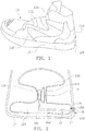
- FIG. 1 is an isometric view of a sports shoe according to a first embodiment of the present application.
- FIG. 2 is a schematic view of an inflatable tightening system of the sports shoe of FIG. 1 .
- the sports shoe with the inflatable tightening system includes a bottom sole 12 and an upper vamp 13 attached to the bottom sole 12.
- the bottom sole 12 is provided with an air cushion 120 which is compressible and stretchable.
- the upper vamp 13 is provided with at least one airbag 130 for covering and abutting against the foot.
- An air-charging valve 14 is provided between the air cushion 120 and the airbag 130.
- An air-intaking valve 15 is provided between the air cushion 120 and the external environment.
- An air-discharging duct 16 is connected between the airbag 130 and the external environment.
- the air-discharging duct 16 is provided with an air-discharging valve 17.
- the air cushion 120 is formed in the bottom sole 12 and located corresponding to the heel part of one' s foot. As a person puts his foot into the upper vamp 13 and the heel part of the foot stamps on the air cushion 120, the air cushion 120 inflates the airbag 130 by using the air-charging valve 14 and the air-intaking valve 15.
- the air-charging valve 14 when the air cushion 120 is compressed, the air-charging valve 14 is opened and the air-intaking valve 15 is closed, such that the air inside the air cushion 120 is filled into the airbag 130; when the air cushion 120 stretches and restores, the air-intaking valve 15 is opened and the air-charging valve 14 is closed, such that the air in the external environment enters into the air cushion 120; when the air-discharging valve 17 is activated to open, the air inside the airbag 130 is discharged out via the air-discharging duct 16; when the air-discharging valve 17 is closed, the air inside the airbag 130 is prevented from being discharged out via the air-discharging duct 16.
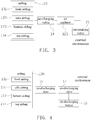
- FIG. 3 is a schematic diagram showing the inflatable tightening system of FIG. 2 when it is inflated.
- FIG. 4 is a schematic diagram showing the inflatable tightening system of FIG. 2 when it is deflated.
- the air-charging valve 14 is opened and the air-intaking valve 15 is closed, such that the air inside the air cushion 120 is pushed into the airbag 130 to inflate the airbag 130;
- the air-intaking valve 15 is opened and the air-charging valve 14 is closed, such that the air in the external environment is supplied into the air cushion 120, to cause the air cushion 120 to stretch and restore back to the original state before being stamped on.
- the foot stamps on the air cushion 120 repeatedly to cause the airbag 130 to be inflated continually, until the airbag 130 is inflated to a state in which the upper vamp 13 fits well with the foot. That is, when the air pressure in the airbag 130 reaches a certain value, the air-charging valve 14 is closed and no longer opens, the air cushion 120 stops to inflate the airbag 130. Thereafter, the air cushion 120 is used as a buffer for the shoe.
- the air-charging valve 14 when the air pressure in the air cushion 120 is greater than the air pressure in the airbag 130, the air-charging valve 14 is opened; when the air pressure in the airbag 130 is greater than the air pressure in the air cushion 120, the air-charging valve 14 is closed; when the air pressure in the air cushion 120 is greater than the air pressure in the external environment, the air-intaking valve 15 is closed; when the air pressure in the external environment is greater than the air pressure in the air cushion 120, the air-intaking valve 15 is opened.
- the air-discharging valve 17 when the air pressure in the airbag 130 is greater than the air pressure in the external environment.
- the air pressure closing the air-charging valve 14 can be determined according to the size or the type (e.g., for men's, women's, children) of the shoe. When the air pressure in the airbag 130 reaches the determined value, the air-charging valve 14 is closed and no longer opens.
- An air-charging channel 140 is connected between the air cushion 120 and the airbag 130, and the air-charging valve 14 is disposed in the air-charging channel 140.
- the air-charging valve 14 When the air-charging valve 14 is opened, the air inside the air cushion 120 is filled into the airbag 130 via the air-charging channel 140; when the air-charging valve 14 is closed, the air in the airbag 130 cannot flow back to the air cushion 120 via the air-charging channel 140.
- An air-intaking channel 150 is connected between the air cushion 120 and the external environment, and the air-intaking valve 15 is disposed in the air-intaking channel 150.
- the air-intaking valve 15 When the air-intaking valve 15 is opened, the air in the external environment is supplied into the air cushion 120 so that the air cushion 120 restores; when the air-intaking valve 15 is closed, the air inside the air cushion 120 cannot flow towards the external environment via the air-intaking channel 150.
- the air-discharging valve 17 is disposed in the air-discharging duct 16. In the embodiment, a first end of the air-discharging duct 16 is communicated with the airbag 130, and a second end of the air-discharging duct 16 extends to a side surface 125 of the bottom sole 12. The air-discharging valve 17 is disposed adjacent to the second end of the air-discharging duct 16. In order to save layout space, the air-intaking valve 15 and the air-discharging valve 17 may be integrated into one valve assembly.
- the air-intaking valve 15 is used to control the air in the external environment to enter into the air cushion 120, while the air-discharging valve 17 is used to control the air in the airbag 130 to be discharged out towards the external environment via the air-discharging duct 16.
- the air-discharging valve 17 is connected with an air-discharging button 18.
- the air-discharging button 18 is used to drive the air-discharging valve 17 to open, such that the air in the airbag 130 can be discharged out via the air-discharging duct 16.
- the air-discharging button 18 is disposed at the side surface 125 of the bottom sole 12, and the air-discharging button 18 is exposed.
- the air-discharging button 18 is disposed at the side surface 125 of the bottom sole 12, the air-discharging button 18 is prevented from being activated unintentionally by external objects to cause the airbag 130 to deflate; when taking off the shoe, the person needs only placing the two shoes worn by him towards each other and using the air-discharging button 18 of one shoe to activate the air-discharging button 18 of the other shoe.
- the air-discharging valves 17 of the two shoes are driven to be opened simultaneously, such that the air inside the airbag 130 of each shoe is discharged out via the air-discharging duct 16, the air pressure inside the airbag 130 is lowered down, the upper vamp 13 of each shoe begins to loosen with respect to the foot, such that the person can finally take off the shoe.
- the person does not have to stoop down to touch the air-discharging button 18 with his hand in order to open the air-discharging valve 17.
- the air-discharging duct 16 is a hose made of a soft material.
- the air-discharging duct 16 is partially received in the air cushion 120, and the air-discharging duct 16 passes through the air cushion 120 to communicate with the airbag 130.
- the air-discharging duct 16 is L-shaped, including a vertical section 161 and a horizontal section 162 connecting with the vertical section 161.
- the vertical section 161 is communicated with the airbag 130, and the horizontal section 162 extends to the side surface 125 of the bottom sole 12.
- a fixing hole 160 is provided between the air cushion 120 and the airbag 130, the vertical section 161 of the air-discharging duct 16 is fixed and sealed in the fixing hole 160, such that the air inside the air cushion 120 cannot flow to the airbag 130 via the fixing hole 160, and the air inside the airbag 130 cannot flow to the air cushion 120 via the fixing hole 160.
- the airbag 130 may include a front airbag 131 adapted for covering a front part of the foot, a side airbag 132 adapted for covering a side part of the foot, a bottom airbag 133 adapted for covering a heel part of the foot, and a top airbag 134 adapted for covering an ankle part of the foot.
- Each shoe may include at least one of these airbags.
- the multiple airbags 130 are distributed over the upper vamp 13, and the multiple airbags 130 are communicated with each other.
- multiple airbags including a front airbag 131, a side airbag 132, a bottom airbag 133 and a top airbag 134 are provided at different locations for each shoe, such that the foot is fully surrounded by the multiple airbags 130, to thereby protect the critical areas of the foot from sports injuries.
- FIG. 5 is an isometric view of a sports shoe according to an example, not forming part of the invention.
- the difference between this embodiment and the above-mentioned first embodiment mainly lies in that, the air-discharging duct 16 is embedded in a sidewall 135 of the upper vamp 13, such that the air-discharging duct 16 does not have to pass through the air cushion 120, it is not required to define a fixing hole 160 between the air cushion 120 and the airbag 130 for fixing the air-discharging duct 16, and it is also not required to think about the sealing problem between the air-discharging duct 16 and the air cushion 120. Therefore, this embodiment has a simpler structure.
- the sports shoe with inflatable tightening system has the following advantages: when the sports shoe is taken on the foot, the air cushion is used to inflate the airbag of the upper vamp automatically. After being inflated, the airbag surrounds the foot to cause the upper vamp of the shoe to fit well with the foot, to thereby improve wearing comfort of the shoe and solve the problem that the existing sports shoe is not comfortable and may incur sports injuries because the upper vamp does not fit well with the foot.
- the sports shoe with inflatable tightening system has the following advantages: when the sports shoe is taken on the foot, the air cushion is used to inflate the airbag of the upper vamp automatically. After being inflated, the airbag surrounds the foot to cause the upper vamp of the shoe to fit well with the foot, to thereby improve wearing comfort of the shoe and solve the problem that the existing sports shoe is not comfortable and may incur sports injuries because the upper vamp does not fit well with the foot.
Landscapes
- Health & Medical Sciences (AREA)
- General Health & Medical Sciences (AREA)
- Physical Education & Sports Medicine (AREA)
- Footwear And Its Accessory, Manufacturing Method And Apparatuses (AREA)
Claims (12)
- Ein Sportschuh mit aufblasbaren Befestigungssystem, bestehend aus:einer Fußsohle (12) die mit einem komprimierbaren und dehnbaren Luftpolster (120) ausgestattet ist;ein Oberleder (13), dass an der Fußsohle (12) befestigt ist, dass Oberleder (13) ist mit zumindest einem Luftpolster (130) ausgestattet und eingerichtet für die Bedeckung des Fußes und Stöße gegen ihn;ein Luft ladendes Ventil (14) dass zwischen dem Luftpolster (120) und zumindest einem der Luftsäcke (130) eingerichtet ist:ein Lufteinlass-Ventil (15) das zwischen dem Luftpolster (120) und der äußeren Umgebung eingerichtet ist; undein Luftablasskanal (16) der zwischen zumindest einem der Luftsäcke (130) und der äußeren Umgebung eingerichtet ist, der Luft-Ablasskanal wird teilweise vom Luftpolster (120) aufgenommen und läuft durch das Luftpolster (120) um mit zumindest einem der Luftsäcke (130) in Verbindung zu treten, der Luftablasskanal (16) ist mit einem Luftablassventil (17) ausgestattet, das Lufteinlass-Ventil (15) und das Luftablassventil (17) sind in eine Ventileinheit integriert;innerhalb derer bei der Kompression des Luftpolsters (120) das Luftladeventil (14) geöffnet und das Lufteinlassventil (15) geschlossen wird, sodass die Luft innerhalb des Luftpolsters in zumindest einen der Luftsäcke (130) gefüllt wird;wenn das Luftpolster (120) sich dehnt und wiederherstellt wird das Lufteinlassventil (15) geöffnet und das Luftladeventil (14) geschlossen, sodass die Luft aus der äußeren Umgebung in das Luftpolster (120) gelangt;wenn das Luftentladeventil (17) zum Öffnen aktiviert wird, wird die Luft aus zumindest einem Luftsack (130) durch den Luftentladekanal (16) entladen;wenn das Luftentladeventil (17) geschlossen wird, dann wird die Luft in zumindest einem Luftsack (130) davon gehindert über den Luftentladekanal (16) entladen zu werden.
- Der Sportschuh von Anspruch 1, in dem der Luftladekanal (140) zwischen dem Luftpolster (120) und zumindest einem Luftsack (130) verbunden ist, und das Luftladeventil (14) in den Luftladekanal (140) entsorgt wird.
- Der Sportschuh von Anspruch 1, in dem der Lufteinlasskanal (150) zwischen Luftpolster (120) und der äußeren Umgebung verbunden ist, und das Lufteinlassventil (15) in den Lufteinlasskanal (150) entsorgt wird.
- Der Sportschuh von Anspruch 1, in dem das Luftablassventil (17) in den Luftablasskanal (16) entsorgt wird, zum Beispiel das erste Ende des Luftablasskanals (16) ist in Verbindung mit zumindest einem Luftsack (130), das zweite Ende des Luftablasskanals (16) ist zur seitlichen Oberfläche (125) der Fußsohle (12) verlängert ist und an das Luftablassventil (17) aneinandergrenzend an daszweiten Ende des Luftablassventils angelegt ist.
- Der Sportschuh von Anspruch 1, in dem das Luftablassventil (17) mit den Luftablassknopf (18) verbunden ist, der Luftablassknopf (18) veranlasst das Luftablassventil (17) sich zu öffnen, wenn der Luftablassknopf (18) aktiviert wird, zum Beispiel, der Lustablassknopf (18) wird zur seitlichen Oberfläche (125) der Fußsohle (12) gesetzt, der Luftablassknopf (18) liegt frei und die Luftablassknöpfe (18) von zwei Sportschuhen eines Paares sind einer dem anderen gegenüber gesetzt.
- Ein Sportschuh von Anspruch 1, in dem der Luftablasskanal (16) ein Schlauch aus weichem Material ist.
- Der Sportschuh aus Anspruch 1, indem der Luftablasskanal (16) in L-Form ist und einen vertikalen (161) und einen horizontalen (162) Abschnitt, der mit dem vertikalen Abschnitt (161) verbunden ist, einschließt; der vertikale Abschnitt (161) steht in Verbindung mit zumindest einem Luftpolster (130) und der horizontalen Abschnitt (162) reicht bis zur seitlichen Oberfläche der Fußsohle (12).
- Der Sportschuh von Anspruch 7, in dem ein Befestigungsloch (160) zwischen dem Luftpolster (120) und zumindest einem Luftsack (130) befindet, der vertikale Teil (161) des Luftablasskanals (16) wird in dem Befestigungsloch (160) befestigt und versiegelt.
- Der Sportschuh von Anspruch 1, in dem zumindest ein Luftsack (130) mehrere Luftsäcke hat, die Luftsäcke sind über das Oberleder (13) verteilt, und mehrere Luftsäcke (130) stehen in Verbindung miteinander, zum Beispiel, zum Beispiel der zumindest ein Luftsack (130) schließt einen der vorderen Luftsäcke (131) ein, der zur Abdeckung des vorderen Teil des Fußes angepasst ist, einen seitlichen Luftsack (132), der zur Abdeckung des Seitenteil des Fußes angepasst ist, einen unteren Luftsack (133), der zur Abdeckung des Hackenteils des Fußes angepasst ist, und einen oberen Luftsack (134), der für die Abdeckung des Knöchelteils des Fußes angepasst ist.
- Der Sportschuh von Anspruch 1, in dem das Luftpolster (120) in der Fußsohle (12) gebildet wird und sich entsprechend des Hackenteiles des Fußes befindet.
- Der Sportschuh von Anspruch 1, wenn der Luftdruck im Luftpolster (120) größer als der Luftdruck in zumindest einem Luftsack (130) ist, dann wird das Luftladeventil (14) geöffnet; wenn der Luftdruck in zumindest einem Luftsack (130) größer ist als im Luftpolster (120) dann wird das Luftladeventil (14) geschlossen; wenn der Luftdruck im Luftpolster (120) größer als der Luftdruck in der äußeren Umgebung ist, dann wird dass Lufteinlassventil (15) geschlossen; wenn der Luftdruck in der äußeren Umgebung größer ist als der Luftdruck im Luftpolster (120), dann wird das Lufteinlassventil (15) geöffnet.
- Der Sportschuh von Anspruch 11, in dem wenn der Luftdruck in zumindest einem Luftsack (130) größer als der Luftdruck in der äußeren Umgebung ist, dass Luftentladeventil (17) geschlossen wird
Applications Claiming Priority (2)
| Application Number | Priority Date | Filing Date | Title |
|---|---|---|---|
| CN201710054976.0A CN106993841A (zh) | 2017-01-24 | 2017-01-24 | 具有充气收紧系统的运动鞋 |
| PCT/CN2017/116895 WO2018137440A1 (en) | 2017-01-24 | 2017-12-18 | Sports shoe with inflatable tightening system |
Publications (3)
| Publication Number | Publication Date |
|---|---|
| EP3547865A1 EP3547865A1 (de) | 2019-10-09 |
| EP3547865A4 EP3547865A4 (de) | 2019-11-06 |
| EP3547865B1 true EP3547865B1 (de) | 2020-09-16 |
Family
ID=59431275
Family Applications (1)
| Application Number | Title | Priority Date | Filing Date |
|---|---|---|---|
| EP17893949.2A Active EP3547865B1 (de) | 2017-01-24 | 2017-12-18 | Sportschuh mit aufblasbarem spannsystem |
Country Status (5)
| Country | Link |
|---|---|
| US (1) | US11083247B2 (de) |
| EP (1) | EP3547865B1 (de) |
| JP (1) | JP6722825B2 (de) |
| CN (1) | CN106993841A (de) |
| WO (1) | WO2018137440A1 (de) |
Families Citing this family (26)
| Publication number | Priority date | Publication date | Assignee | Title |
|---|---|---|---|---|
| EP3445198B1 (de) | 2016-04-22 | 2022-12-14 | Fast IP, LLC | Schuhwerk mit schnellem einstieg und rückfederungspasssystem |
| CN106993841A (zh) | 2017-01-24 | 2017-08-01 | 浙江吉利控股集团有限公司 | 具有充气收紧系统的运动鞋 |
| CN108464564B (zh) * | 2018-05-31 | 2020-05-26 | 中国人民解放军陆军军医大学第一附属医院 | 便捷式手术用拖鞋 |
| WO2020006490A1 (en) | 2018-06-28 | 2020-01-02 | Fast Ip, Llc | Rapid-entry footwear having an actuator arm |
| WO2020146113A1 (en) | 2019-01-07 | 2020-07-16 | Fast Ip, Llc | Rapid-entry footwear having a compressible lattice structure |
| EP3930527B1 (de) | 2019-02-26 | 2025-09-24 | Fast IP, LLC | Schuhwerk für schnelles anziehen mit einem fersenarm und einem elastischen element |
| JP2021022064A (ja) * | 2019-07-25 | 2021-02-18 | 豊田合成株式会社 | 触感提示装置 |
| EP4640101A3 (de) | 2019-07-29 | 2025-12-24 | Fast IP, LLC | Schuh zum schnellen anziehen mit einem stabilisator und einem elastischen element |
| US10905192B1 (en) * | 2019-09-03 | 2021-02-02 | Fast Ip, Llc | Rapid-entry footwear having a pocket for a compressed medium |
| AU2020344538B2 (en) | 2019-09-09 | 2024-01-11 | Fast Ip, Llc | Rapid-entry footwear having an arm for expanding an opening |
| WO2021077098A1 (en) | 2019-10-17 | 2021-04-22 | Fast Ip, Llc | Rapid-entry footwear comprised of a unified material |
| US11576468B2 (en) | 2019-10-24 | 2023-02-14 | Nike, Inc. | Vacuum adjustment device for article of apparel or footwear |
| CA3165989A1 (en) | 2020-01-28 | 2021-08-05 | Fast Ip, Llc | Rapid-entry footwear having rotatable straps |
| CN115697125A (zh) * | 2020-05-29 | 2023-02-03 | 耐克创新有限合伙公司 | 用于鞋类物品的缓冲鞋面 |
| WO2022081735A1 (en) | 2020-10-13 | 2022-04-21 | Fast Ip, Llc | Rapid-entry footwear having a rotating rear portion and a fulcrum |
| CN116507235A (zh) | 2020-11-20 | 2023-07-28 | 飞思特知识产权有限责任公司 | 具有分裂后部的快速进入式鞋类 |
| CN116847752A (zh) | 2021-02-17 | 2023-10-03 | 飞思特知识产权有限责任公司 | 具有变形鞋床的快速进入式鞋类 |
| WO2022204444A1 (en) | 2021-03-24 | 2022-09-29 | Fast Ip, Llc | Rapid-entry footwear having a rotating tongue |
| CN113208226A (zh) * | 2021-05-27 | 2021-08-06 | 李青 | 一种助力鞋 |
| WO2023049414A1 (en) | 2021-09-23 | 2023-03-30 | Fast Ip, Llc | Rapid-entry footwear having a multi-action counter |
| US12471677B2 (en) | 2021-11-10 | 2025-11-18 | Nike, Inc. | Bladders, footwear uppers including bladders, and articles of footwear including bladders in the upper |
| CN114658876B (zh) * | 2022-03-23 | 2024-05-10 | 特技阀门集团有限公司 | 一种带智能控制系统的球阀 |
| CN115155047B (zh) * | 2022-06-20 | 2024-09-13 | 中国人民解放军西部战区总医院 | 一种防止足踝扭伤的装置及其使用方法 |
| CN116548699A (zh) * | 2023-05-04 | 2023-08-08 | 宁波德士马实业有限公司 | 一种鞋面可拆卸的安全鞋 |
| CN122295018A (zh) * | 2023-12-19 | 2026-06-26 | 耐克创新有限合伙公司 | 用于鞋类制品的调节系统 |
| US12672699B2 (en) | 2023-12-19 | 2026-07-07 | Nike, Inc. | Adjustment system for article of footwear |
Family Cites Families (31)
| Publication number | Priority date | Publication date | Assignee | Title |
|---|---|---|---|---|
| US850327A (en) * | 1906-11-16 | 1907-04-16 | Isidor Tauber | Pneumatic tread for boots and shoes. |
| US5846063A (en) * | 1987-05-26 | 1998-12-08 | Nikola Lakic | Miniature universal pump and valve for inflatable liners |
| US4991317A (en) * | 1987-05-26 | 1991-02-12 | Nikola Lakic | Inflatable sole lining for shoes and boots |
| US5025575A (en) * | 1989-03-14 | 1991-06-25 | Nikola Lakic | Inflatable sole lining for shoes and boots |
| US6014823A (en) * | 1987-05-26 | 2000-01-18 | Lakic; Nikola | Inflatable sole lining for shoes and boots |
| AU631191B2 (en) | 1989-02-08 | 1992-11-19 | Reebok International Ltd. | An article of footwear |
| US4999932A (en) * | 1989-02-14 | 1991-03-19 | Royce Medical Company | Variable support shoe |
| US5392534A (en) | 1992-10-23 | 1995-02-28 | Grim; Tracy E. | Vacuum formed conformable shoe |
| CN2337805Y (zh) * | 1998-05-08 | 1999-09-15 | 杨思军 | 一种鞋底 |
| CN2396670Y (zh) * | 1999-10-14 | 2000-09-20 | 杨玉平 | 气垫排汗运动鞋 |
| US6463679B1 (en) * | 1999-10-21 | 2002-10-15 | Yamamoto Limited | Forced ventilation system inside soles |
| US6409486B1 (en) * | 2000-09-12 | 2002-06-25 | Dc Shoes, Inc. | Shoe with inflatable bladder and secure deflation valve |
| US20040010939A1 (en) * | 2001-09-24 | 2004-01-22 | Liu Chang Yuen | Shoes having ventilation devices |
| US6785985B2 (en) * | 2002-07-02 | 2004-09-07 | Reebok International Ltd. | Shoe having an inflatable bladder |
| US8677652B2 (en) * | 2002-07-02 | 2014-03-25 | Reebok International Ltd. | Shoe having an inflatable bladder |
| US7278445B2 (en) * | 2002-07-02 | 2007-10-09 | Reebok International Ltd. | Shoe having an inflatable bladder |
| CN2627868Y (zh) * | 2003-03-05 | 2004-07-28 | 代贵民 | 通风气垫保健鞋 |
| KR100534033B1 (ko) * | 2003-07-12 | 2005-12-08 | 주식회사 피스포스 | 신발의 펌핑구조 |
| CN2703434Y (zh) * | 2004-03-11 | 2005-06-08 | 庄铭焕 | 带充气气囊的鞋帮面 |
| US7013585B2 (en) * | 2004-08-12 | 2006-03-21 | Chie-Fang Lo | Cushion device for shoes |
| US7478488B1 (en) * | 2005-10-31 | 2009-01-20 | Reebok International Ltd. | Inflatable and ventilating upper for an article of footwear |
| CN201097691Y (zh) * | 2007-07-06 | 2008-08-13 | 王伟康 | 一种运动鞋鞋底 |
| US20100199518A1 (en) * | 2007-08-28 | 2010-08-12 | Prontopharma-Europe S.R.L. | Sole including a system of blisters and devices for their deflation |
| US8800167B2 (en) * | 2009-09-19 | 2014-08-12 | Harold S. Doyle | Pneumatic inflating device contained entirely within shoe sole |
| CN102894540A (zh) * | 2012-10-29 | 2013-01-30 | 程建英 | 喷气式助力鞋底 |
| CN103783731B (zh) * | 2012-10-31 | 2016-03-30 | 欣合信股份有限公司 | 可手动与自动控压的鞋气垫 |
| CN103431574A (zh) * | 2013-08-26 | 2013-12-11 | 陈兆平 | 全方位充气运动鞋 |
| CN204104979U (zh) * | 2014-11-07 | 2015-01-21 | 李秀杰 | 具有排气功能的运动鞋 |
| CN205597252U (zh) * | 2016-02-23 | 2016-09-28 | 张萌 | 一种可充气运动鞋 |
| CN106993841A (zh) * | 2017-01-24 | 2017-08-01 | 浙江吉利控股集团有限公司 | 具有充气收紧系统的运动鞋 |
| US10258102B2 (en) * | 2017-03-07 | 2019-04-16 | Welter's Co., Ltd. | Airbag device with pressure regulating function |
-
2017
- 2017-01-24 CN CN201710054976.0A patent/CN106993841A/zh active Pending
- 2017-12-18 EP EP17893949.2A patent/EP3547865B1/de active Active
- 2017-12-18 US US16/480,668 patent/US11083247B2/en active Active
- 2017-12-18 WO PCT/CN2017/116895 patent/WO2018137440A1/en not_active Ceased
- 2017-12-18 JP JP2019524416A patent/JP6722825B2/ja active Active
Non-Patent Citations (1)
| Title |
|---|
| None * |
Also Published As
| Publication number | Publication date |
|---|---|
| JP6722825B2 (ja) | 2020-07-15 |
| CN106993841A (zh) | 2017-08-01 |
| US20210127788A1 (en) | 2021-05-06 |
| EP3547865A1 (de) | 2019-10-09 |
| JP2019533544A (ja) | 2019-11-21 |
| WO2018137440A1 (en) | 2018-08-02 |
| EP3547865A4 (de) | 2019-11-06 |
| US11083247B2 (en) | 2021-08-10 |
Similar Documents
| Publication | Publication Date | Title |
|---|---|---|
| US11083247B2 (en) | Sports shoe with inflatable tightening system | |
| US10251450B2 (en) | Shoe having an inflatable bladder | |
| US7340851B2 (en) | Shoe having an inflatable bladder | |
| EP0389215B1 (de) | Laufschuh mit gepresster Knöchelstütze | |
| JP5219510B2 (ja) | 膨張可能空気袋を有する履物の空気抜きメカニズム | |
| US4999932A (en) | Variable support shoe | |
| CN101415349A (zh) | 具有可充气鞋舌的运动鞋 | |
| KR20090111748A (ko) | 기능성 굴림 신발창 |
Legal Events
| Date | Code | Title | Description |
|---|---|---|---|
| STAA | Information on the status of an ep patent application or granted ep patent |
Free format text: STATUS: THE INTERNATIONAL PUBLICATION HAS BEEN MADE |
|
| PUAI | Public reference made under article 153(3) epc to a published international application that has entered the european phase |
Free format text: ORIGINAL CODE: 0009012 |
|
| STAA | Information on the status of an ep patent application or granted ep patent |
Free format text: STATUS: REQUEST FOR EXAMINATION WAS MADE |
|
| 17P | Request for examination filed |
Effective date: 20190701 |
|
| AK | Designated contracting states |
Kind code of ref document: A1 Designated state(s): AL AT BE BG CH CY CZ DE DK EE ES FI FR GB GR HR HU IE IS IT LI LT LU LV MC MK MT NL NO PL PT RO RS SE SI SK SM TR |
|
| AX | Request for extension of the european patent |
Extension state: BA ME |
|
| STAA | Information on the status of an ep patent application or granted ep patent |
Free format text: STATUS: EXAMINATION IS IN PROGRESS |
|
| A4 | Supplementary search report drawn up and despatched |
Effective date: 20191007 |
|
| RIC1 | Information provided on ipc code assigned before grant |
Ipc: A43B 5/00 20060101AFI20190930BHEP |
|
| 17Q | First examination report despatched |
Effective date: 20191017 |
|
| REG | Reference to a national code |
Ref country code: DE Ref legal event code: R079 Ref document number: 602017023937 Country of ref document: DE Free format text: PREVIOUS MAIN CLASS: A43B0005000000 Ipc: A43B0013200000 |
|
| GRAP | Despatch of communication of intention to grant a patent |
Free format text: ORIGINAL CODE: EPIDOSNIGR1 |
|
| STAA | Information on the status of an ep patent application or granted ep patent |
Free format text: STATUS: GRANT OF PATENT IS INTENDED |
|
| RIC1 | Information provided on ipc code assigned before grant |
Ipc: A43C 11/00 20060101ALI20200317BHEP Ipc: A43B 13/20 20060101AFI20200317BHEP Ipc: A43B 23/02 20060101ALI20200317BHEP |
|
| DAV | Request for validation of the european patent (deleted) | ||
| DAX | Request for extension of the european patent (deleted) | ||
| INTG | Intention to grant announced |
Effective date: 20200402 |
|
| GRAS | Grant fee paid |
Free format text: ORIGINAL CODE: EPIDOSNIGR3 |
|
| GRAA | (expected) grant |
Free format text: ORIGINAL CODE: 0009210 |
|
| STAA | Information on the status of an ep patent application or granted ep patent |
Free format text: STATUS: THE PATENT HAS BEEN GRANTED |
|
| AK | Designated contracting states |
Kind code of ref document: B1 Designated state(s): AL AT BE BG CH CY CZ DE DK EE ES FI FR GB GR HR HU IE IS IT LI LT LU LV MC MK MT NL NO PL PT RO RS SE SI SK SM TR |
|
| REG | Reference to a national code |
Ref country code: GB Ref legal event code: FG4D |
|
| REG | Reference to a national code |
Ref country code: CH Ref legal event code: EP |
|
| REG | Reference to a national code |
Ref country code: DE Ref legal event code: R096 Ref document number: 602017023937 Country of ref document: DE |
|
| REG | Reference to a national code |
Ref country code: IE Ref legal event code: FG4D |
|
| REG | Reference to a national code |
Ref country code: AT Ref legal event code: REF Ref document number: 1313306 Country of ref document: AT Kind code of ref document: T Effective date: 20201015 |
|
| PG25 | Lapsed in a contracting state [announced via postgrant information from national office to epo] |
Ref country code: FI Free format text: LAPSE BECAUSE OF FAILURE TO SUBMIT A TRANSLATION OF THE DESCRIPTION OR TO PAY THE FEE WITHIN THE PRESCRIBED TIME-LIMIT Effective date: 20200916 Ref country code: NO Free format text: LAPSE BECAUSE OF FAILURE TO SUBMIT A TRANSLATION OF THE DESCRIPTION OR TO PAY THE FEE WITHIN THE PRESCRIBED TIME-LIMIT Effective date: 20201216 Ref country code: BG Free format text: LAPSE BECAUSE OF FAILURE TO SUBMIT A TRANSLATION OF THE DESCRIPTION OR TO PAY THE FEE WITHIN THE PRESCRIBED TIME-LIMIT Effective date: 20201216 Ref country code: SE Free format text: LAPSE BECAUSE OF FAILURE TO SUBMIT A TRANSLATION OF THE DESCRIPTION OR TO PAY THE FEE WITHIN THE PRESCRIBED TIME-LIMIT Effective date: 20200916 Ref country code: GR Free format text: LAPSE BECAUSE OF FAILURE TO SUBMIT A TRANSLATION OF THE DESCRIPTION OR TO PAY THE FEE WITHIN THE PRESCRIBED TIME-LIMIT Effective date: 20201217 Ref country code: HR Free format text: LAPSE BECAUSE OF FAILURE TO SUBMIT A TRANSLATION OF THE DESCRIPTION OR TO PAY THE FEE WITHIN THE PRESCRIBED TIME-LIMIT Effective date: 20200916 |
|
| REG | Reference to a national code |
Ref country code: AT Ref legal event code: MK05 Ref document number: 1313306 Country of ref document: AT Kind code of ref document: T Effective date: 20200916 |
|
| REG | Reference to a national code |
Ref country code: NL Ref legal event code: MP Effective date: 20200916 |
|
| PG25 | Lapsed in a contracting state [announced via postgrant information from national office to epo] |
Ref country code: LV Free format text: LAPSE BECAUSE OF FAILURE TO SUBMIT A TRANSLATION OF THE DESCRIPTION OR TO PAY THE FEE WITHIN THE PRESCRIBED TIME-LIMIT Effective date: 20200916 Ref country code: RS Free format text: LAPSE BECAUSE OF FAILURE TO SUBMIT A TRANSLATION OF THE DESCRIPTION OR TO PAY THE FEE WITHIN THE PRESCRIBED TIME-LIMIT Effective date: 20200916 |
|
| REG | Reference to a national code |
Ref country code: LT Ref legal event code: MG4D |
|
| PG25 | Lapsed in a contracting state [announced via postgrant information from national office to epo] |
Ref country code: CZ Free format text: LAPSE BECAUSE OF FAILURE TO SUBMIT A TRANSLATION OF THE DESCRIPTION OR TO PAY THE FEE WITHIN THE PRESCRIBED TIME-LIMIT Effective date: 20200916 Ref country code: RO Free format text: LAPSE BECAUSE OF FAILURE TO SUBMIT A TRANSLATION OF THE DESCRIPTION OR TO PAY THE FEE WITHIN THE PRESCRIBED TIME-LIMIT Effective date: 20200916 Ref country code: PT Free format text: LAPSE BECAUSE OF FAILURE TO SUBMIT A TRANSLATION OF THE DESCRIPTION OR TO PAY THE FEE WITHIN THE PRESCRIBED TIME-LIMIT Effective date: 20210118 Ref country code: EE Free format text: LAPSE BECAUSE OF FAILURE TO SUBMIT A TRANSLATION OF THE DESCRIPTION OR TO PAY THE FEE WITHIN THE PRESCRIBED TIME-LIMIT Effective date: 20200916 Ref country code: SM Free format text: LAPSE BECAUSE OF FAILURE TO SUBMIT A TRANSLATION OF THE DESCRIPTION OR TO PAY THE FEE WITHIN THE PRESCRIBED TIME-LIMIT Effective date: 20200916 Ref country code: LT Free format text: LAPSE BECAUSE OF FAILURE TO SUBMIT A TRANSLATION OF THE DESCRIPTION OR TO PAY THE FEE WITHIN THE PRESCRIBED TIME-LIMIT Effective date: 20200916 |
|
| PG25 | Lapsed in a contracting state [announced via postgrant information from national office to epo] |
Ref country code: AL Free format text: LAPSE BECAUSE OF FAILURE TO SUBMIT A TRANSLATION OF THE DESCRIPTION OR TO PAY THE FEE WITHIN THE PRESCRIBED TIME-LIMIT Effective date: 20200916 Ref country code: AT Free format text: LAPSE BECAUSE OF FAILURE TO SUBMIT A TRANSLATION OF THE DESCRIPTION OR TO PAY THE FEE WITHIN THE PRESCRIBED TIME-LIMIT Effective date: 20200916 Ref country code: ES Free format text: LAPSE BECAUSE OF FAILURE TO SUBMIT A TRANSLATION OF THE DESCRIPTION OR TO PAY THE FEE WITHIN THE PRESCRIBED TIME-LIMIT Effective date: 20200916 Ref country code: IS Free format text: LAPSE BECAUSE OF FAILURE TO SUBMIT A TRANSLATION OF THE DESCRIPTION OR TO PAY THE FEE WITHIN THE PRESCRIBED TIME-LIMIT Effective date: 20210116 Ref country code: PL Free format text: LAPSE BECAUSE OF FAILURE TO SUBMIT A TRANSLATION OF THE DESCRIPTION OR TO PAY THE FEE WITHIN THE PRESCRIBED TIME-LIMIT Effective date: 20200916 |
|
| REG | Reference to a national code |
Ref country code: DE Ref legal event code: R097 Ref document number: 602017023937 Country of ref document: DE |
|
| PG25 | Lapsed in a contracting state [announced via postgrant information from national office to epo] |
Ref country code: SK Free format text: LAPSE BECAUSE OF FAILURE TO SUBMIT A TRANSLATION OF THE DESCRIPTION OR TO PAY THE FEE WITHIN THE PRESCRIBED TIME-LIMIT Effective date: 20200916 |
|
| PLBE | No opposition filed within time limit |
Free format text: ORIGINAL CODE: 0009261 |
|
| STAA | Information on the status of an ep patent application or granted ep patent |
Free format text: STATUS: NO OPPOSITION FILED WITHIN TIME LIMIT |
|
| REG | Reference to a national code |
Ref country code: CH Ref legal event code: PL |
|
| 26N | No opposition filed |
Effective date: 20210617 |
|
| PG25 | Lapsed in a contracting state [announced via postgrant information from national office to epo] |
Ref country code: DK Free format text: LAPSE BECAUSE OF FAILURE TO SUBMIT A TRANSLATION OF THE DESCRIPTION OR TO PAY THE FEE WITHIN THE PRESCRIBED TIME-LIMIT Effective date: 20200916 Ref country code: SI Free format text: LAPSE BECAUSE OF FAILURE TO SUBMIT A TRANSLATION OF THE DESCRIPTION OR TO PAY THE FEE WITHIN THE PRESCRIBED TIME-LIMIT Effective date: 20200916 Ref country code: MC Free format text: LAPSE BECAUSE OF FAILURE TO SUBMIT A TRANSLATION OF THE DESCRIPTION OR TO PAY THE FEE WITHIN THE PRESCRIBED TIME-LIMIT Effective date: 20200916 |
|
| REG | Reference to a national code |
Ref country code: BE Ref legal event code: MM Effective date: 20201231 |
|
| PG25 | Lapsed in a contracting state [announced via postgrant information from national office to epo] |
Ref country code: IE Free format text: LAPSE BECAUSE OF NON-PAYMENT OF DUE FEES Effective date: 20201218 Ref country code: LU Free format text: LAPSE BECAUSE OF NON-PAYMENT OF DUE FEES Effective date: 20201218 Ref country code: IT Free format text: LAPSE BECAUSE OF FAILURE TO SUBMIT A TRANSLATION OF THE DESCRIPTION OR TO PAY THE FEE WITHIN THE PRESCRIBED TIME-LIMIT Effective date: 20200916 |
|
| PG25 | Lapsed in a contracting state [announced via postgrant information from national office to epo] |
Ref country code: LI Free format text: LAPSE BECAUSE OF NON-PAYMENT OF DUE FEES Effective date: 20201231 Ref country code: CH Free format text: LAPSE BECAUSE OF NON-PAYMENT OF DUE FEES Effective date: 20201231 |
|
| PG25 | Lapsed in a contracting state [announced via postgrant information from national office to epo] |
Ref country code: TR Free format text: LAPSE BECAUSE OF FAILURE TO SUBMIT A TRANSLATION OF THE DESCRIPTION OR TO PAY THE FEE WITHIN THE PRESCRIBED TIME-LIMIT Effective date: 20200916 Ref country code: MT Free format text: LAPSE BECAUSE OF FAILURE TO SUBMIT A TRANSLATION OF THE DESCRIPTION OR TO PAY THE FEE WITHIN THE PRESCRIBED TIME-LIMIT Effective date: 20200916 Ref country code: CY Free format text: LAPSE BECAUSE OF FAILURE TO SUBMIT A TRANSLATION OF THE DESCRIPTION OR TO PAY THE FEE WITHIN THE PRESCRIBED TIME-LIMIT Effective date: 20200916 |
|
| PG25 | Lapsed in a contracting state [announced via postgrant information from national office to epo] |
Ref country code: MK Free format text: LAPSE BECAUSE OF FAILURE TO SUBMIT A TRANSLATION OF THE DESCRIPTION OR TO PAY THE FEE WITHIN THE PRESCRIBED TIME-LIMIT Effective date: 20200916 |
|
| PG25 | Lapsed in a contracting state [announced via postgrant information from national office to epo] |
Ref country code: BE Free format text: LAPSE BECAUSE OF NON-PAYMENT OF DUE FEES Effective date: 20201231 |
|
| PG25 | Lapsed in a contracting state [announced via postgrant information from national office to epo] |
Ref country code: NL Free format text: LAPSE BECAUSE OF NON-PAYMENT OF DUE FEES Effective date: 20200923 |
|
| PGFP | Annual fee paid to national office [announced via postgrant information from national office to epo] |
Ref country code: GB Payment date: 20251104 Year of fee payment: 9 |
|
| PGFP | Annual fee paid to national office [announced via postgrant information from national office to epo] |
Ref country code: FR Payment date: 20251117 Year of fee payment: 9 |
|
| PGFP | Annual fee paid to national office [announced via postgrant information from national office to epo] |
Ref country code: DE Payment date: 20251222 Year of fee payment: 9 |