EP3548207B1 - Rouleau de coulée et procédé de coulée d'une bande métallique à réglage de couronne - Google Patents
Rouleau de coulée et procédé de coulée d'une bande métallique à réglage de couronne Download PDFInfo
- Publication number
- EP3548207B1 EP3548207B1 EP18706193.2A EP18706193A EP3548207B1 EP 3548207 B1 EP3548207 B1 EP 3548207B1 EP 18706193 A EP18706193 A EP 18706193A EP 3548207 B1 EP3548207 B1 EP 3548207B1
- Authority
- EP
- European Patent Office
- Prior art keywords
- casting
- expansion
- roll
- expansion elements
- cylindrical tube
- Prior art date
- Legal status (The legal status is an assumption and is not a legal conclusion. Google has not performed a legal analysis and makes no representation as to the accuracy of the status listed.)
- Active
Links
Images





Classifications
-
- B—PERFORMING OPERATIONS; TRANSPORTING
- B22—CASTING; POWDER METALLURGY
- B22D—CASTING OF METALS; CASTING OF OTHER SUBSTANCES BY THE SAME PROCESSES OR DEVICES
- B22D11/00—Continuous casting of metals, i.e. casting in indefinite lengths
- B22D11/06—Continuous casting of metals, i.e. casting in indefinite lengths into moulds with travelling walls, e.g. with rolls, plates, belts, caterpillars
- B22D11/0622—Continuous casting of metals, i.e. casting in indefinite lengths into moulds with travelling walls, e.g. with rolls, plates, belts, caterpillars formed by two casting wheels
-
- B—PERFORMING OPERATIONS; TRANSPORTING
- B22—CASTING; POWDER METALLURGY
- B22D—CASTING OF METALS; CASTING OF OTHER SUBSTANCES BY THE SAME PROCESSES OR DEVICES
- B22D11/00—Continuous casting of metals, i.e. casting in indefinite lengths
- B22D11/06—Continuous casting of metals, i.e. casting in indefinite lengths into moulds with travelling walls, e.g. with rolls, plates, belts, caterpillars
- B22D11/0637—Accessories therefor
- B22D11/0648—Casting surfaces
- B22D11/0651—Casting wheels
-
- B—PERFORMING OPERATIONS; TRANSPORTING
- B22—CASTING; POWDER METALLURGY
- B22D—CASTING OF METALS; CASTING OF OTHER SUBSTANCES BY THE SAME PROCESSES OR DEVICES
- B22D11/00—Continuous casting of metals, i.e. casting in indefinite lengths
- B22D11/06—Continuous casting of metals, i.e. casting in indefinite lengths into moulds with travelling walls, e.g. with rolls, plates, belts, caterpillars
- B22D11/0637—Accessories therefor
- B22D11/0665—Accessories therefor for treating the casting surfaces, e.g. calibrating, cleaning, dressing, preheating
-
- B—PERFORMING OPERATIONS; TRANSPORTING
- B22—CASTING; POWDER METALLURGY
- B22D—CASTING OF METALS; CASTING OF OTHER SUBSTANCES BY THE SAME PROCESSES OR DEVICES
- B22D11/00—Continuous casting of metals, i.e. casting in indefinite lengths
- B22D11/16—Controlling or regulating processes or operations
- B22D11/168—Controlling or regulating processes or operations for adjusting the mould size or mould taper
Definitions
- This invention relates to the casting of metal strip by continuous casting in a twin roll caster.
- the invention relates to a casting roll, for the casting of metal strip by continuous casting in a twin roll caster,
- the thickness of a casting roll tube often is less than 120 mm, e.g. less than 100 mm or even less than 80 mm.
- the casting roll tube material usually is selected from the group consisting of copper and copper alloy, optionally with a coating thereon.
- the casting roll usually has a plurality of longitudinal water flow passages extending through the cylindrical tube.
- the invention also refers to an apparatus for continuously casting thin strip by controlling roll crown and to a method of continuously casting thin strip by controlling roll crown,
- molten metal is introduced between a pair of counter-rotated horizontal casting rolls that are cooled so that metal shells solidify on the moving roll surfaces and are brought together at a nip between them to produce a solidified strip product delivered downwardly from the nip between the rolls.
- the term "nip" is used herein to refer to the general region at which the rolls are closest together.
- the molten metal may be poured from a ladle into a smaller vessel or series of smaller vessels from which it flows through a metal delivery nozzle located above the nip forming a casting pool of molten metal supported on the casting surfaces of the rolls immediately above the nip and extending along the length of the nip. This casting pool is usually confined between side plates or dams held in sliding engagement with end surfaces of the rolls so as to dam the two ends of the casting pool against outflow.
- the twin roll caster is capable of continuously producing cast strip from molten steel through a sequence of ladles positioned on a turret. Pouring the molten metal from the ladle into a tundish and then a moveable tundish before flowing through the metal delivery nozzle enables the exchange of an empty ladle for a full ladle on the turret without disrupting the production of the cast strip.
- the crown of the casting surfaces of the casting rolls varies during a casting campaign.
- the crown of the casting surfaces of the casting rolls in turn determines the strip thickness profile, i.e., cross-sectional shape, of the thin cast strip produce by the twin roll caster.
- Casting rolls with convex (i.e. positive crown) casting surfaces produce cast strip with a negative (i.e. depressed) cross-sectional shape; and casting rolls with concave (i.e. negative crown) casting surfaces produce cast strip with a positive (i.e. raised) cross-sectional shape.
- the casting rolls generally are formed of copper or copper alloy, usually coated with chromium or nickel, with internal passages for circulation of cooling water enabling high heat fluxes for rapid solidification where the casting rolls undergo substantial thermal deformation with exposure to the molten metal during a casting campaign.
- a roll crown is desired to produce a desired strip cross-sectional thickness profile under typical casting conditions. It is usual to machine the casting rolls when cold with an initial crown based on the projected crown in the casting surfaces of the casting rolls during casting. However, the differences between the shape of the casting surfaces of the casting rolls between cold and casting conditions are difficult to predict. Moreover, the crown of the casting surfaces of the casting rolls during the casting campaign can vary significantly. The crown of the casting surfaces of the casting rolls can change during casting due to changes in the temperature of the molten metal supplied to the casting pool of the caster, changes in casting speed of the casting rolls, and other casting conditions, such as slight changes in molten steel composition.
- WO 2016/083506 A1 discloses a method of controlling casting roll crown and, in turn, the cross-sectional strip thickness profile by controlling the crown in the casting surfaces by expansion rings positioned within and adjacent cylindrical tubes forming the casting rolls.
- the expansion rings are heated electrically, here at the edges of the casting roll and/or in the center of the casting roll. This method already shows some positive effect to control edge drop.
- Patent documents FR1343136 , WO2016/107715 and EP0429385 also disclose a method of controlling the casting roll crown.
- One object of the present invention is to further reduce the peaks and valleys of the strip surface across the strip width.
- Switching electrical power supply from one or more expansion elements to one or more other expansion elements means that electrical power which is fed into one or more expansion elements is reduced, while electrical power which is fed into one or more other expansion elements is increased.
- the reduction of electrical power for a specific expansion element can, but will in most cases not be, reduced to zero when the electrical power fed into one or more expansion elements is reduced.
- a specific expansion element can at that moment already receive electrical power, or it does at that moment not receive electrical power.
- the expansion elements are distributed along the cylindrical tube (which is also referred to as the casting roll sleeve) it is possible to vary the diameter of the casting surface and/or the temperature of the casting surface for the whole casting surface, and not just for the edges or the center.
- a multitude of expansion elements is necessary to locally vary the diameter of the casting surface and/or the temperature of the casting surface.
- the invention needs at least two expansion elements per casting roll, it is preferred that at least three expansion elements are provided. Still more preferred are more than ten, more than fifteen or even more than twenty expansion elements per casting roll. So a typical number of expansion elements are sixteen to thirty axially symmetric expansion elements, such as expansion rings.
- the axially symmetric expansion elements such as expansion rings, are distributed along the entire length of the cylindrical tube including the end portions of the casting surface.
- a power switch is situated in or on the casting roll, this in order to distribute the totally available electrical power that is supplied to the casting roll for e.g. expansion element heating to many of the connected expansion elements in equal portions or at different percentages.
- expansion element can be heated separately by using electricity, and thus can be controlled in temperature separately.
- an expansion element preferably the multitude of the expansion elements, especially each expansion element, has a width (measured parallel to the axis of the casting roll) between 40 and 150 mm, preferably between 40 and 100 mm, more preferably between 50 and 85 mm.
- the expansion elements can have the form of a ring which per definition has a central hole, or the expansion elements can have the form of a disk, without a center ring hole.
- the outer diameter of the expansion element shall in any case be tolerance-fitted with the roll tube inner diameter.
- each expansion ring is has a radial ring thickness (i.e. the difference between outer and inner diameter of the ring) between 40 and 150 mm, preferably between 40 and 100 mm, more preferably 45 - 75 mm.
- the expansion rings can be mounted on an internal pipe, preferably having a wall thickness of at least 10-50 mm and at least an outer diameter of not less than 110 mm onto which the expansion rings are tolerance fitted.
- the axial position of the expansion rings on the internal pipe can be fixed by spacers between the rings or by respective press fit tolerances of the rings (e.g. shrinkage mounted rings).
- each expansion element is equipped with electrical resistance heating elements being able to supply the expansion ring with up to 15 kW, preferably 3-10 kW heating power.
- the electrical resistance heating elements can be wires or rods in the form of a ring which are in contact with the expansion elements.
- the total electrical energy power provided for all expansion elements together can be up to 70 kW, preferably not more than 35 kW per meter of external circumference of the casting roll.
- a claimed embodiment of the invention is that a centrally mounted expansion element is constructed as to be permanently heated. This assures contact between the outer surface of the expansion element and the inner surface of the cylindrical tube (casting roll sleeve) or even an outward bulging of the cylindrical tube, superposed to the local (thermal) crown.
- the centrally mounted expansion element may have the same width as most other expansion rings or may have a significantly larger width than all other expansion rings, e.g. up to 150 until 400 mm.
- the expansion elements located at the end portions of the casting surface are constructed as to be permanently heated. Again, this assures contact between the outer surface of the two expansion elements and the inner surface of the cylindrical tube (casting roll sleeve) or even an outward bulging of the cylindrical tube, superposed to the local (thermal) crown at the ends of the cylindrical tube.
- a preferred embodiment of the invention is that a controller is constructed to control the radial dimension of each of the expansion elements responsive to at least a temperature process model of the casting roll and/or the expansion rings, or responsive to temperature measurements foreseen within some or all of the expansion elements, by respective temperature sensors.
- the expansion elements can be equipped with at least one temperature sensor each, for providing respective signals to the controller.
- a preferred embodiment of the invention is that the expansion elements are equipped with at least one RFID-tag each, for identifying the expansion element when sending temperature information to a controller, preferably a controller situated within the casting roll.
- Such a controller e.g. a microcontroller
- a microcontroller can be part of a main controller of the control system and can be connected to the RFID-tags for detecting temperature and evaluating the temperature values.
- the microcontroller can issue a thermal profile over all expansion elements (i.e. over the width of the casting roll) every two to sixty seconds, preferably every five to thirty seconds, and send it to the main controller which uses this temperature profile (e.g. in combination with a thermal profile computed by a process model) as input for control which expansion elements are to be increased, i.e. heated.
- An apparatus according to the invention for continuously casting thin strip by controlling roll crown comprises
- the object of the present invention is also achieved by a method of continuously casting thin strip by controlling roll crown disclosed in appended claim 13.
- control of which expansion elements are to be increased is done on the basis of the measured temperature of expansion elements, the temperature of two or more expansion elements of one casting roll is measured, or the temperature of two or more expansion elements of both casting rolls is measured.
- the temperature profile of one or both of the casting rolls is given by a process model which outputs in real time a two- or three-dimensional temperature field of the interior of the cylindrical tube.
- the temperature profile of one or both of the casting rolls is given by a process model which outputs in real time the average temperature of each expansion element.
- the process model is real time calculating the two- or three-dimensional temperature field within the cylindrical tube (casting roll sleeve) and/or the average temperature of each expansion element in calculation cycle which last at least one, two or up to fifteen seconds, as well as the average temperature of the cylindrical tube (casting roll sleeve) in a circular cross section and can hence - by means of a deformation field calculation for the cylindrical tube (casting roll sleeve) and for the expansion elements - forecast which of the expansion elements is touching the cylindrical tube and must be heated and hence dilated more or less to eliminate certain strip profile valleys or strip surface temperature spots.
- the process model for the temperature field within the cylindrical tube (casting roll sleeve) and the process model for the average temperature of each expansion element can be designed as separate models and can therefore be used and calculated separately.
- the process model for the temperature field within the cylindrical tube (casting roll sleeve) can help save external sensors.
- the process model for the average temperature of each expansion element can help save the temperature sensors within the expansion elements.
- artificial intelligence or machine learning methods and models may be used to fine tune the selection of heat rings for heating.
- a preferred embodiment of the invention is that additionally artificial intelligence, e.g. in form of a neural network algorithm or a symbolic regression algorithm, is used for determining which expansion elements have to be increased, preferably heated.
- One preferred embodiment of the invention provides that only a centrally mounted expansion element is permanently increased, preferably heated.
- the expansion elements located at the end portions of the casting surface are permanently increased, preferably heated.
- At least one of the casting rolls is designed according to the claimed casting roll.
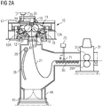
- a twin roll caster is illustrated that comprises a main machine frame 10 that stands up from the factory floor and supports a pair of counter-rotatable casting rolls 12 mounted in a module in a roll cassette 11.
- the casting rolls 12 are mounted in the roll cassette 11 for ease of operation and movement as described below.
- the roll cassette 11 facilitates rapid movement of the casting rolls 12 ready for casting from a setup position into an operative casting position in the caster as a unit, and ready removal of the casting rolls 12 from the casting position when the casting rolls 12 are to be replaced.
- the casting apparatus for continuously casting thin steel strip includes the pair of counter-rotatable casting rolls 12 having casting surfaces 12A laterally positioned to form a nip 18 there between.
- Molten metal is supplied from a ladle 13 through a metal delivery system to a metal delivery nozzle 17, core nozzle, positioned between the casting rolls 12 above the nip 18.
- Molten metal thus delivered forms a casting pool 19 of molten metal above the nip 18 supported on the casting surfaces 12A of the casting rolls 12.
- This casting pool 19 is confined in the casting area at the ends of the casting rolls 12 by a pair of side closure plates, or side dams 20, (shown in dotted line in FIGS. 2A and 2B ).
- the upper surface of the casting pool 19 (generally referred to as the "meniscus" level) may rise above the lower end of the delivery nozzle 17 so that the lower end of the delivery nozzle 17 is immersed within the casting pool 19.
- the casting area includes the addition of a protective atmosphere above the casting pool 19 to inhibit oxidation of the molten metal in the casting area.
- the ladle 13 typically is of a conventional construction supported on a rotating turret 40.
- the ladle 13 is positioned over a movable tundish 14 in the casting position to fill the tundish 14 with molten metal.
- the movable tundish 14 may be positioned on a tundish car 66 capable of transferring the tundish 14 from a heating station (not shown), where the tundish 14 is heated to near a casting temperature, to the casting position.
- a tundish guide, such as rails 39, may be positioned beneath the tundish car 66 to enable moving the movable tundish 14 from the heating station to the casting position.
- the movable tundish 14 may be fitted with a slide gate 25, actuable by a servo mechanism, to allow molten metal to flow from the tundish 14 through the slide gate 25, and then through a refractory outlet shroud 15 to a transition piece or distributor 16 in the casting position. From the distributor 16, the molten metal flows to the delivery nozzle 17 positioned between the casting rolls 12 above the nip 18.
- the side dams 20 may be made from a refractory material such as zirconia graphite, graphite alumina, boron nitride, boron nitride-zirconia, or other suitable composites.
- the side dams 20 have a face surface capable of physical contact with the casting rolls 12 and molten metal in the casting pool 19.
- the side dams 20 are mounted in side dam holders (not shown), which are movable by side dam actuators (not shown), such as a hydraulic or pneumatic cylinder, servo mechanism, or other actuator to bring the side dams 20 into engagement with the ends of the casting rolls 12. Additionally, the side dam actuators are capable of positioning the side dams 20 during casting.
- the side dams 20 form end closures for the molten pool of metal on the casting rolls 12 during the casting operation.
- FIG. 1 shows the twin roll caster producing the cast strip 21, which passes across a guide table 30 to a pinch roll stand 31, comprising pinch rolls 31 A.
- the thin cast strip 21 may pass through a hot rolling mill 32, comprising a pair of work rolls 32A, and backup rolls 32B, forming a gap capable of hot rolling the cast strip 21 delivered from the casting rolls 12, where the cast strip 21 is hot rolled to reduce the strip to a desired thickness, improve the strip surface, and improve the strip flatness.
- the work rolls 32A have work surfaces relating to the desired strip profile across the work rolls 32A.
- the hot rolled cast strip 21 then passes onto a run-out table 33, where it may be cooled by contact with a coolant, such as water, supplied via water jets 90 or other suitable means, and by convection and radiation. In any event, the hot rolled cast strip 21 may then pass through a second pinch roll stand 91 to provide tension of the cast strip 21, and then to a coiler 92.
- the cast strip 21 may be between about 0.3 and 2.0 millimeters in thickness before hot rolling.
- a short length of imperfect strip is typically produced as casting conditions stabilize.
- the casting rolls 12 are moved apart slightly and then brought together again to cause this leading end of the cast strip 21 to break away forming a clean head end of the following cast strip 21.
- the imperfect material drops into a scrap receptacle 26, which is movable on a scrap receptacle guide.
- the scrap receptacle 26 is located in a scrap receiving position beneath the caster and forms part of a sealed enclosure 27 as described below.
- the enclosure 27 is typically water cooled.
- a water-cooled apron 28 that normally hangs downwardly from a pivot 29 to one side in the enclosure 27 is swung into position to guide the clean end of the cast strip 21 onto the guide table 30 that feeds it to the pinch roll stand 31.
- the apron 28 is then retracted back to its hanging position to allow the cast strip 21 to hang in a loop beneath the casting rolls 12 in enclosure 27 before it passes to the guide table 30 where it engages a succession of guide rollers.
- An overflow container 38 may be provided beneath the movable tundish 14 to receive molten material that may spill from the tundish 14. As shown in FIG. 1 , the overflow container 38 may be movable on rails 39 or another guide such that the overflow container 38 may be placed beneath the movable tundish 14 as desired in casting locations. Additionally, an optional overflow container (not shown) may be provided for the distributor 16 adjacent the distributor 16.
- the sealed enclosure 27 is formed by a number of separate wall sections that fit together at various seal connections to form a continuous enclosure wall that permits control of the atmosphere within the enclosure 27. Additionally, the scrap receptacle 26 may be capable of attaching with the enclosure 27 so that the enclosure 27 is capable of supporting a protective atmosphere immediately beneath the casting rolls 12 in the casting position.
- the enclosure 27 includes an opening in the lower portion of the enclosure 27, lower enclosure portion 44, providing an outlet for scrap to pass from the enclosure 27 into the scrap receptacle 26 in the scrap receiving position.
- the lower enclosure portion 44 may extend downwardly as a part of the enclosure 27, the opening being positioned above the scrap receptacle 26 in the scrap receiving position.
- a rim portion 45 may surround the opening of the lower enclosure portion 44 and may be movably positioned above the scrap receptacle 26, capable of sealingly engaging and/or attaching to the scrap receptacle 26 in the scrap receiving position.
- the rim portion 45 may be movable between a sealing position in which the rim portion 45 engages the scrap receptacle 26, and a clearance position in which the rim portion 45 is disengaged from the scrap receptacle 26.
- the caster or the scrap receptacle 26 may include a lifting mechanism to raise the scrap receptacle 26 into sealing engagement with the rim portion 45 of the enclosure 27, and then lower the scrap receptacle 26 into the clearance position.
- the enclosure 27 and scrap receptacle 26 are filled with a desired gas, such as nitrogen, to reduce the amount of oxygen in the enclosure 27 and provide a protective atmosphere for the cast strip 21.
- the enclosure 27 may include an upper collar portion 43 supporting a protective atmosphere immediately beneath the casting rolls 12 in the casting position.
- the upper collar portion 43 is moved to the extended position closing the space between a housing portion 53 adjacent the casting rolls 12, as shown in FIG. 2 , and the enclosure 27.
- the upper collar portion 43 may be provided within or adjacent the enclosure 27 and adjacent the casting rolls 12, and may be moved by a plurality of actuators (not shown) such as servo-mechanisms, hydraulic mechanisms, pneumatic mechanisms, and rotating actuators.
- the casting rolls 12 are internally water cooled as described below so that as the casting rolls 12 are counter-rotated, shells solidify on the casting surfaces 12A, as the casting surfaces 12A move into contact with and through the casting pool 19 with each revolution of the casting rolls 12.
- the shells are brought close together at the nip 18 between the casting rolls 12 to produce a thin cast strip product 21 delivered downwardly from the nip 18.
- the thin cast strip product 21 is formed from the shells at the nip 18 between the casting rolls 12 and delivered downwardly and moved downstream as described above.
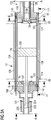
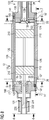
- each casting roll 12 includes a cylindrical tube 120 of a metal selected from the group consisting of copper and copper alloy, optionally with a coating thereon, e.g., chromium or nickel, to form the casting surfaces 12A.
- a coating thereon e.g., chromium or nickel.
- an expansion ring 220 may be positioned within and adjacent the cylindrical tube 120 at a position corresponding to center portions of the cast strip formed on the casting surfaces of the casting rolls during casting.
- Each cylindrical tube 120 may be mounted between a pair of stub shaft assemblies 121 and 122.
- the stub shaft assemblies 121 and 122 have end portions 127 and 128, respectively (shown in FIGS 4-6 ), which fit snugly within the ends of cylindrical tube 120 to form the casting roll 12.
- the cylindrical tube 120 is thus supported by end portions 127 and 128 having flange portions 129 and 130, respectively, to form internal cavity 163 therein, and support the assembled casting roll between the stub shaft assemblies 121 and 122.
- each cylindrical tube 120 is a roll casting surface 12A.
- the radial thickness of the cylindrical tube 120 may be no more than 80 millimeters thick.
- the thickness of the tube 120 may range between 40 and 80 millimeters in thickness or between 60 and 80 millimeters in thickness.
- Each cylindrical tube 120 is provided with a series of longitudinal water flow passages 126, which may be formed by drilling long holes through the circumferential thickness of the cylindrical tube 120 from one end to the other. The ends of the holes are subsequently closed by end plugs 141 attached to the end portions 127 and 128 of stub shaft assemblies 121 and 122 by fasteners 171.
- the water flow passages 126 are formed through the thickness of the cylindrical tube 120 with end plugs 141.
- the number of stub shaft fasteners 171 and end plugs 141 may be selected as desired.
- End plugs 141 may be arranged to provide, with water passage in the stub shaft assemblies described below, in single pass cooling from one end to the other of the roll 12, or alternatively, to provide multi-pass cooling where, for example, the flow passages 126 are connected to provide three passes of cooling water through adjacent flow passages 126 before returning the water to the water supply directly or through the cavity 163.
- the water flow passages 126 through the thickness of the cylindrical tube 120 may be connected to water supply in series with the cavity 163.
- the water passages 126 may be connected to the water supply so that the cooling water first passes through the cavity 163 and then the water supply passages 126 to the return lines, or first through the water supply passages 126 and then through the cavity 163 to the return lines.
- the cylindrical tube 120 may be provided with circumferential steps 123 at end to form shoulders 124 with the working portion of the roll casting surface 12A of the roll 12 there between.
- the shoulders 124 are arranged to engage the side dams 20 and confine the casting pool 19 as described above during the casting operation.
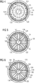
- End portions 127 and 128 of stub shaft assemblies 121 and 122 typically sealingly engage the ends of cylindrical tube 120 and have radially extending water passages 135 and 136 shown in FIGS. 4-6 to deliver water to the water flow passages 126 extending through the cylindrical tube 120.
- the radial flow passages 135 and 136 are connected to the ends of at least some of the water flow passages 126, for example, in threaded arrangement, depending on whether the cooling is a single pass or multi-pass cooling system.
- the remaining ends of the water flow passages 126 may be closed by, for example, threaded end plugs 141 as described where the water cooling is a multi-pass system.
- cylindrical tube 120 may be positioned in annular arrays in the thickness of cylindrical tube 120 either in single pass or multi-pass arrays of water flow passages 126 as desired.
- the water flow passages 126 are connected at one end of the casting roll 12 by radial ports 160 to the annular gallery 140 and in turn radially flow passages 135 of end portion 127 in stub shaft assembly 120, and are connected at the other end of the casting roll 12 by radial ports 161 to annular gallery 150 and in turn radial flow passages 136 of end portions 128 in stub shaft assembly 121.
- Water supplied through one annular gallery, 140 or 150, at one end of the roll 12 can flow in parallel through all of the water flow passages 126 in a single pass to the other end of the roll 12 and out through the radial passages, 135 or 136, and the other annular gallery, 150 or 140, at that other end of the cylindrical tube 120.
- the directional flow may be reversed by appropriate connections of the supply and return line(s) as desired.
- selective ones of the water flow passages 126 may be optionally connected or blocked from the radial passages 135 and 136 to provide a multi pass arrangement, such as a three pass.
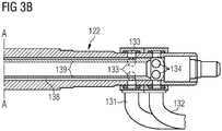
- the stub shaft assembly 122 may be longer than the stub shaft assembly 121, and the stub shaft assembly 122 provided with two sets of water flow ports 133 and 134.
- Water flow ports 133 and 134 are capable of connection with rotary water flow couplings 131 and 132 by which water is delivered to and from the casting roll 12 axially through stub shaft assembly 122.
- cooling water passes to and from the water flow passages 126 in the cylindrical tube 120 through radial passages 135 and 136 extending through end portions 127 and 128 of the stub shaft assemblies 121 and 122, respectively.
- the stub shaft assembly 121 is fitted with axial tube 137, to provide fluid communication between the radial passages 135 in end portions 127 and the central cavity within the casting roll 12.
- the stub shaft assembly 122 is fitted with axial space tube 138, to separate a central water duct 138, in fluid communication with the central cavity 163, and from annular water flow duct 139 in fluid communication with radial passages 136 in end portion 122 of stub shaft assembly 122.
- Central water duct 138 and annular water duct 139 are capable of providing inflow and outflow of cooling water to and from the casting roll 12.
- incoming cooling water may be supplied through supply line 131 to annular duct 139 through ports 133, which is in turn in fluid communication with the radial passages 136, gallery 150 and water flow passages 126, and then returned through the gallery 140, the radial passages 135, axial tube 137, central cavity 163, and central water duct 138 to outflow line 132 through water flow ports 134.
- the water flow to, from and through the casting roll 12 may be in the reverse direction as desired.
- the water flow ports 133 and 134 may be connected to water supply and return lines so that water may flow to and from water flow passages 126 in the cylindrical tube 120 of the casting roll 12 in either direction, as desired.
- the cooling water flows through the cavity 163 either before or after flow through the water flow passages 126.
- each cylindrical tube 120 is usually provided with more than three expansion rings.
- each cylindrical tube 120 may be provided with at least two expansion rings 210 spaced on opposite end portions of the cylindrical tube 120 inward within 450 mm of edge portions of the cast strip formed on opposite end portions of the casting rolls during the casting campaign.
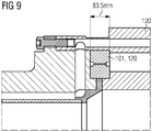
- FIG. 9 which also belongs to prior art, shows a cross sectional view longitudinally through a portion of a casting roll with an expansion ring 210 spaced from the edge portions of the cast strip.
- two expansion rings 210 may be spaced on opposite end portions of the cylindrical tube within 450 mm of edge portions of the cast strip formed on opposite end portions of the casting rolls during the casting campaign and an additional expansion ring 200 may be positioned within and adjacent the cylindrical tube 120 at a position corresponding to center portions of the cast strip formed on the casting surfaces of the casting rolls during casting.
- Power wire 222 and control wire 224 extend from slip ring 220 to each expansion ring.
- Power wire 222 supplies the energy to electrically power the expansion ring 200, 210.
- Control wire 224 modulates the energy to electrically power the expansion ring.
- FIG. 11 is a sectional view longitudinally through a casting roll with nineteen expansion rings 101-119 according to the present invention, whereas the inner part of the casting roll 12 has been omitted.
- expansion rings 101-119 have approximately the same width and the same ring thickness.
- Expansion rings 101 and 119 are located at the edge of the casting surface 12A. Seen in axial direction, part of the expansion ring 101, 119 is located within the casting surface 12A and part of the expansion ring 101, 119 is located outside the casting surface 12A.
- the distance of an expansion ring 101, 119 at the edge of the casting surface 12A to the next expansion ring 102, 118 is here larger than the distance between two adjacent inner expansion rings 102-118.
- the distance of an expansion ring 101, 119 at the edge of the casting surface 12A to the next expansion ring 102, 118 in this example is between 1,0 and 1,5 the width of one expansion ring 101-119.
- the distance between two adjacent inner expansion rings 102-118 is less than the width of one expansion ring 101-119, here approximately between 0,5 and 0,8 the width of one expansion ring 101-119.
- the expansion rings 101-119 are mounted on the outer surface of an internal pipe 180, e.g. by shrinkage mounting.
- This internal pipe 180 can contain the wires or cables for providing electrical energy from the wires 181 to each of the expansion rings 101-119.
- a power switch can be situated in the internal pipe 180 in order to switch electrical power supply from one or more expansion rings to one or more other expansion rings.
- the internal pipe 180 can also contain part of the water cooling, similar to FIG. 4-7 .
- the centrally mounted expansion ring which would be expansion ring 110 in this case, could be permanently connected to the wires 181 so as to be heated permanently, or the power switch is constructed or programmed or controlled as to permanently heat the centrally mounted expansion ring 110.
- the same could apply to the expansion rings 101 and 119 which are located at the edge of the casting surface 12A.
- Each expansion ring 101-119 is equipped with electrical resistance heating elements which supply each expansion ring with up to 15 kW, preferably 3-10 kW heating power via wires 181 leading to and from a slip ring (not to be seen here).
- the total electrical power provided through the slip ring of one casting roll may total up to 70, preferably up to 35 kW per meter of external circumference of the respective casting roll.
- a controller can be situated outside the casting roll 12 and can be connected via control wires (not shown) with the heating elements of the expansion rings 101-119 or the power switch in the internal pipe 180.
- the controller controls the radial dimension of each of the expansion rings 101-119 by controlling the electrical energy provided to each expansion ring 101-119, e.g. responsive to at least a temperature process model of the casting roll 12 and/or the expansion rings 101-119 and/or responsive to a measured expansion ring temperature.
- Deformation of the crown of the casting surfaces may be controlled by regulating the radial dimension of the respective expansion rings 101-119 located inside the cylindrical tube 120.
- the radial dimension of the expansion rings 101-119 may be controlled by regulating the temperature of the expansion ring.
- the thickness profile of cast strip may be controlled with the control of the crown of the casting surfaces 12A of the casting rolls 12. Since the circumferential thickness of the cylindrical tube 120 normally is made to a thickness of no more than 120 mm, the crown of the casting surfaces 12A may be deformed responsive to changes in the radial dimension of the expansion rings 101-119.
- Each expansion ring 101-119 is adapted to increase in radial dimension causing the cylindrical tube 120 to expand changing the crown of the casting surfaces 12A and the thickness profile of the cast strip 21 during casting.
- Each expansion ring is electrically heated increasing in radial dimension.
- Each expansion ring 101-119 may provide a heating input of up to 15 kW; preferably, of 3-10 kW.
- the force generated from the increase in radial dimension will be applied on the cylindrical tube 120 causing the cylindrical tube to expand changing the crown of the casting surfaces and the thickness profile of the cast strip.
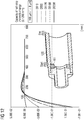
- FIG. 12 shows the effect of expansion ring temperature on the cast strip thickness profile.
- Fig. 12 is a graph of the profile correction of half strip thickness versus the length along the cylindrical tube (mm) for expansion temperatures from 40°C to 200°C.
- a strip thickness profile sensor 71 may be positioned downstream to detect the thickness profile of the cast strip 21 as shown in FIGS. 2 and 2A .
- the strip thickness sensor 71 is provided typically between the nip 18 and the pinch rolls 31A to provide for direct control of the casting roll 12.
- the sensor may be an x-ray gauge or other suitable device capable of directly measuring the thickness profile across the width of the strip periodically or continuously.
- a plurality of non-contact type sensors are arranged across the cast strip 21 at the roller table 30 and the combination of thickness measurements from the plurality of positions across the cast strip 21 are processed by a controller 72 to determine the thickness profile of the strip periodically or continuously.
- the thickness profile of the cast strip 21 may be determined from this data periodically or continuously as desired.
- each expansion ring 101-119 may be independently controlled from the radial dimension of the other expansion rings.
- the sensor 71 generates signals indicative of the thickness profile of the cast strip 21.
- the radial dimension of each expansion rings 101-119 is controlled according to the signals generated by the sensor, which in turns control roll crown of the casting surfaces 12A of the casting rolls 12 during the casting campaign.
- the casting roll drive may be controlled to vary the speed of rotation of the casting rolls while also varying the radial dimension of the expansion ring 101-119 responsive to the electrical signals received from the sensor 71 controlling in turn the roll crown of the casting surfaces of the casting rolls during the casting campaign.
- the expansion rings may be made of an austenitic stainless steel such as 18/8 austenitic stainless steel.
- Each expansion ring may have an annular dimension between 40 to 100 millimeters.
- Each expansion ring 101-119 may have a width of up to 200 millimeters, preferably between 50 and 100 mm, more preferably between 60 and 85 mm.
- the centrally mounted expansion ring 110 may have a larger width than all other expansion rings, e.g. up to 150 until 400 mm.
Landscapes
- Engineering & Computer Science (AREA)
- Mechanical Engineering (AREA)
- Continuous Casting (AREA)
Claims (20)
- Rouleau de coulée (12) pour la coulée d'une bande métallique (21) par coulée continue dans une machine de coulée entre cylindres,ayant une surface de coulée (12A) formée par un tube sensiblement cylindrique (120),ayant des éléments d'expansion axialement symétriques, tels que des bagues d'expansion (101-119), agencés dans et de manière adjacente au tube cylindrique (120), chaque élément d'expansion étant espacé d'un autre élément d'expansion, et les éléments d'expansion étant adaptés pour augmenter en dimension radiale, amenant le tube cylindrique à expanser la cambrure de rouleau de changement des surfaces de coulée des rouleaux de coulée et le profil d'épaisseur de la bande coulée pendant la coulée,ayant une multitude d'éléments d'expansion axialement symétriques, telles que des bagues d'expansion (101-119), qui sont répartis le long de toute la longueur du tube cylindrique (120) et un interrupteur d'alimentation est situé dans ou sur le rouleau de coulée (12) afin de commuter l'alimentation électrique des éléments d'expansion (101-119) d'un ou de plusieurs éléments d'expansion aux un ou plusieurs autres éléments d'expansion en utilisant un fil d'alimentation (181), de sorte que chaque élément d'expansion (101-119) est équipé d'éléments chauffants à résistance électrique qui peuvent fournir à l'élément d'expansion jusqu'à 15 kW, de préférence 3-10 kW de puissance de chauffage et en ce qu'un élément d'expansion (110) monté de manière centrale est construit afin d'être chauffé en permanence, caractérisé en ce que l'interrupteur d'alimentation est construit pour commuter la puissance d'alimentation entre différents éléments d'expansion (101-119) toutes les deux à trente secondes, de préférence toutes les cinq à quinze secondes.
- Rouleau de coulée (12) selon la revendication 1, caractérisé en ce qu'un élément d'expansion (101-119) a une largeur comprise entre 40 et 150 mm, de préférence entre 40 et 100 mm, encore de préférence entre 50 et 85 mm.
- Rouleau de coulée (12) selon la revendication 1 ou 2, caractérisé en ce que chaque bague d'expansion (101-119) a une épaisseur de bague radiale comprise entre 40 et 150 mm, de préférence entre 40 et 100 mm.
- Rouleau de coulée (12) selon l'une des revendications précédentes, caractérisé en ce que les éléments d'expansion ont la forme d'une bague (101-119) ou d'un disque.
- Rouleau de coulée selon la revendication 1, caractérisé en ce que la puissance électrique totale fournie pour tous les éléments d'expansion (101-119) ensemble va jusqu'à 70 kW, de préférence non supérieure à 35 kW, par mètre de circonférence externe du rouleau de coulée (12).
- Rouleau de coulée (12) selon l'une des revendications précédentes, caractérisé en ce que plus de quinze, de préférence de seize à trente éléments d'expansion axialement symétriques, telles que des bagues d'expansion (101-119), sont agencés à l'intérieur de et de manière adjacente au tube cylindrique (120) .
- Rouleau de coulée (12) selon l'une des revendications précédentes, caractérisé en ce qu'une multitude d'éléments d'expansion axialement symétriques, telles que des bagues d'expansion (101-119), sont répartis le long de toute la longueur du tube cylindrique (120) comprenant les parties d'extrémité de la surface de coulée (12A).
- Rouleau de coulée (12) selon la revendication 1, caractérisé en ce que les éléments d'expansion (101, 119) positionnés au niveau des parties d'extrémité de la surface de coulée (12A), sont construits afin d'être chauffés en permanence.
- Rouleau de coulée (12) selon l'une des revendications précédentes, caractérisé en ce que les éléments d'expansion (101-119) sont équipés avec au moins un capteur de température chacun, pour fournir des signaux respectifs à un organe de commande.
- Rouleau de coulée (12) selon l'une des revendications précédentes, caractérisé en ce que les éléments d'expansion (101-119) sont équipés avec au moins une étiquette RFID chacun, pour identifier l'élément d'expansion lors de l'envoi de l'information de température à un organe de commande, de préférence un organe de commande situé à l'intérieur du rouleau de coulée (12).
- Rouleau de coulée (12) selon l'une des revendications précédentes, caractérisé en ce qu'un organe de commande est construit pour contrôler la dimension radiale de chacun des éléments d'expansion (101-119) en réponse à au moins un modèle de traitement de température du rouleau de coulée (12) et/ou un modèle de traitement de température des éléments d'expansion (101-119) et/ou aux changements de température mesurés pour les éléments d'expansion (101-119).
- Appareil pour couler, en continu, une fine bande en commandant la cambrure d'un rouleau, comprenant :une paire de rouleaux de coulée contrarotatifs (12) avec une ligne de contact (18) entre eux pouvant délivrer la bande coulée (21) vers le bas à partir de la ligne de contact, chaque rouleau de coulée ayant une surface de coulée (12A) formée par un tube sensiblement cylindrique (120),un système de distribution de métal positionné au-dessus de la ligne de contact (18) et pouvant former un bassin de coulée (19) supporté sur les surfaces de coulée des rouleaux de coulée (12) avec des barrages latéraux (20) adjacents aux extrémités de la ligne de contact pour confiner le bassin de coulée,caractérisé en ce qu'au moins un rouleau de coulée (12) est conçu selon l'une des revendications 1 à 11.
- Procédé pour couler, en continu, une bande fine en commandant une cambrure d'un rouleau, comprenant les étapes consistant à :utiliser une paire de rouleaux de coulée contrarotatifs (12) avec une ligne de contact (18) entre eux pour délivrer une bande coulée (21) vers le bas à partir de la ligne de contact, chaque rouleau de coulée ayant une surface de coulée (12A) formée par un tube sensiblement cylindrique (120),utiliser en outre un système de distribution de métal positionné au-dessus de la ligne de contact (18) afin de former un bassin de coulée (19) supporté sur les surfaces de coulée (12A) des rouleaux de coulée (12) avec des barrages latéraux (20) adjacents aux extrémités de la ligne de contact afin de confiner le bassin de coulée,au moins un rouleau de coulée (12) ayant des éléments d'expansion axialement symétriques, telles que des bagues d'expansion (101-119), agencés à l'intérieur et de manière adjacente au tube cylindrique (120), chaque élément d'expansion étant espacé d'un autre élément d'expansion, et les éléments d'expansion étant adaptés pour augmenter en dimension radiale, amenant le tube cylindrique (120) à expanser la cambrure d'un rouleau de changement des surfaces de coulée des rouleaux de coulée et le profil d'épaisseur de la bande coulée (21) pendant la coulée,au moins un élément d'expansion est augmenté en dimension radiale, de préférence par chauffage, amenant le tube cylindrique (120) à s'expanser alors qu'au moins un autre élément d'expansion n'augmente pas en dimension radiale, tandis que la commande de ces éléments d'expansion qui doivent être augmentés, est réalisée sur la base de :le profil de température enregistré de la bande coulée (21), et/oule profil d'épaisseur de bande mesuré de la bande coulée (21), et/oula couronne chaude mesurée des rouleaux de coulée (12), et/oule profil de température d'un ou des deux des rouleaux de coulée (12), et/oula température mesurée des éléments d'expansion,caractérisé en ce que la commutation entre différents éléments d'expansion (101-119) est réalisée toutes les deux à soixante secondes, de préférence toutes les cinq à trente secondes.
- Procédé selon la revendication 13, caractérisé en ce que le profil de température d'un ou des deux rouleaux de coulée (12) est donné par un modèle de traitement qui produit en temps réel un champ de température en deux ou trois dimensions de l'intérieur du tube cylindrique (120).
- Procédé selon l'une quelconque des revendications 13 ou 14, caractérisé en ce que le profil de température d'un ou de deux des rouleaux de coulée (12) est donné par un modèle de traitement qui produit en temps réel la température moyenne de chaque élément d'expansion (101-119).
- Procédé selon l'une quelconque des revendications 13 à 15, caractérisé en ce que l'on utilise de plus l'intelligence artificielle, par exemple sous la forme d'un algorithme de réseau neural ou d'un algorithme de régression symbolique, pour déterminer quels éléments d'expansion (101-119) doivent être augmentés, de préférence chauffés.
- Procédé selon l'une quelconque des revendications 13 à 16, caractérisé en ce qu'uniquement trois à neuf, de préférence trois à cinq éléments d'expansion sont augmentés, de préférence chauffés, à la fois.
- Procédé selon l'une quelconque des revendications 13 à 17, caractérisé en ce qu'uniquement un élément d'expansion (110) monté de manière centrale est augmenté en permanence, de préférence chauffé.
- Procédé selon la revendication 18, caractérisé en ce que les éléments d'expansion (101, 109) positionnés au niveau des parties d'extrémité de la surface de coulée (12A) sont augmentés en permanence, de préférence chauffés.
- Procédé selon l'une quelconque des revendications 13 à 19, caractérisé en ce qu'au moins l'un des rouleaux de coulée (12) est conçu selon l'une des revendications 1 à 11.
Applications Claiming Priority (2)
| Application Number | Priority Date | Filing Date | Title |
|---|---|---|---|
| AT500702017 | 2017-01-31 | ||
| PCT/EP2018/052269 WO2018141744A1 (fr) | 2017-01-31 | 2018-01-30 | Rouleau de coulée et procédé de coulée de bande de métal à réglage de bombage |
Publications (2)
| Publication Number | Publication Date |
|---|---|
| EP3548207A1 EP3548207A1 (fr) | 2019-10-09 |
| EP3548207B1 true EP3548207B1 (fr) | 2021-11-17 |
Family
ID=61249601
Family Applications (1)
| Application Number | Title | Priority Date | Filing Date |
|---|---|---|---|
| EP18706193.2A Active EP3548207B1 (fr) | 2017-01-31 | 2018-01-30 | Rouleau de coulée et procédé de coulée d'une bande métallique à réglage de couronne |
Country Status (5)
| Country | Link |
|---|---|
| EP (1) | EP3548207B1 (fr) |
| JP (1) | JP6865840B2 (fr) |
| KR (1) | KR102365633B1 (fr) |
| CN (1) | CN110214060B (fr) |
| WO (1) | WO2018141744A1 (fr) |
Families Citing this family (5)
| Publication number | Priority date | Publication date | Assignee | Title |
|---|---|---|---|---|
| EP3556488A1 (fr) | 2018-04-19 | 2019-10-23 | Primetals Technologies Austria GmbH | Rouleau de coulée et procédé de coulée de bande de métal avec commande de couronne |
| EP4405120A4 (fr) * | 2021-09-29 | 2025-07-30 | Nucor Corp | Application d'un agent d'apprentissage pour réaliser le fonctionnement autonome d'une machine à couler à cylindres jumelés |
| DE102022204686A1 (de) | 2022-05-13 | 2023-11-16 | Sms Group Gmbh | Zwei-Rollen-Gießeinrichtung zur Erzeugung eines gegossenen Metallbandes, und Verfahren zur Kühlung und/oder Reinigung einer Außenoberfläche einer Gießrolle einer Zwei-Rollen-Gießeinrichtung |
| DE102022207236A1 (de) | 2022-07-15 | 2024-01-18 | Sms Group Gmbh | Gießrolle für eine Stranggießanlage |
| CN115971436B (zh) * | 2023-03-16 | 2023-05-26 | 张家港中美超薄带科技有限公司 | 一种控制薄带钢凸度的方法 |
Family Cites Families (6)
| Publication number | Priority date | Publication date | Assignee | Title |
|---|---|---|---|---|
| FR1343136A (fr) * | 1962-01-19 | 1963-11-15 | Goodyear Tire & Rubber | Appareil et procédé de calandrage |
| FR2654656A1 (fr) * | 1989-11-22 | 1991-05-24 | Siderurgie Fse Inst Rech | Cylindre pour dispositif de coulee continue de bandes minces de metal. |
| CH696063A5 (de) * | 2001-09-18 | 2006-12-15 | Main Man Inspiration Ag | Giessrolle für eine Zweirollen-Giessmaschine. |
| GB2522873A (en) * | 2014-02-07 | 2015-08-12 | Siemens Vai Metals Tech Gmbh | A method of forming tailored cast blanks |
| WO2016083506A1 (fr) * | 2014-11-28 | 2016-06-02 | Siemens Vai Metals Technologies Gmbh | Procédé de coulée d'une bande métallique à réglage de couronne |
| DE102014226998A1 (de) * | 2014-12-29 | 2016-06-30 | Siemens Vai Metals Technologies Gmbh | Rolle für eine metallurgische Anlage |
-
2018
- 2018-01-30 CN CN201880009590.0A patent/CN110214060B/zh active Active
- 2018-01-30 EP EP18706193.2A patent/EP3548207B1/fr active Active
- 2018-01-30 WO PCT/EP2018/052269 patent/WO2018141744A1/fr not_active Ceased
- 2018-01-30 KR KR1020197025557A patent/KR102365633B1/ko active Active
- 2018-01-30 JP JP2019541337A patent/JP6865840B2/ja active Active
Non-Patent Citations (1)
| Title |
|---|
| None * |
Also Published As
| Publication number | Publication date |
|---|---|
| KR102365633B1 (ko) | 2022-02-18 |
| JP2020505236A (ja) | 2020-02-20 |
| CN110214060B (zh) | 2022-08-30 |
| WO2018141744A1 (fr) | 2018-08-09 |
| CN110214060A (zh) | 2019-09-06 |
| KR20190112788A (ko) | 2019-10-07 |
| JP6865840B2 (ja) | 2021-04-28 |
| EP3548207A1 (fr) | 2019-10-09 |
Similar Documents
| Publication | Publication Date | Title |
|---|---|---|
| EP3204177B1 (fr) | Procédé de coulée d'une bande métallique à réglage de couronne | |
| US20210001396A1 (en) | Method for casting metal strip with crown control | |
| EP3548207B1 (fr) | Rouleau de coulée et procédé de coulée d'une bande métallique à réglage de couronne | |
| EP2313220B1 (fr) | Procédé de coulée de bande de métal avec régulation dynamique du bombage | |
| US11148193B2 (en) | Method for casting metal strip with edge control | |
| US8607847B2 (en) | Method for casting metal strip with dynamic crown control | |
| EP3556488A1 (fr) | Rouleau de coulée et procédé de coulée de bande de métal avec commande de couronne |
Legal Events
| Date | Code | Title | Description |
|---|---|---|---|
| STAA | Information on the status of an ep patent application or granted ep patent |
Free format text: STATUS: UNKNOWN |
|
| STAA | Information on the status of an ep patent application or granted ep patent |
Free format text: STATUS: THE INTERNATIONAL PUBLICATION HAS BEEN MADE |
|
| PUAI | Public reference made under article 153(3) epc to a published international application that has entered the european phase |
Free format text: ORIGINAL CODE: 0009012 |
|
| STAA | Information on the status of an ep patent application or granted ep patent |
Free format text: STATUS: REQUEST FOR EXAMINATION WAS MADE |
|
| 17P | Request for examination filed |
Effective date: 20190705 |
|
| AK | Designated contracting states |
Kind code of ref document: A1 Designated state(s): AL AT BE BG CH CY CZ DE DK EE ES FI FR GB GR HR HU IE IS IT LI LT LU LV MC MK MT NL NO PL PT RO RS SE SI SK SM TR |
|
| AX | Request for extension of the european patent |
Extension state: BA ME |
|
| DAV | Request for validation of the european patent (deleted) | ||
| DAX | Request for extension of the european patent (deleted) | ||
| STAA | Information on the status of an ep patent application or granted ep patent |
Free format text: STATUS: EXAMINATION IS IN PROGRESS |
|
| 17Q | First examination report despatched |
Effective date: 20200526 |
|
| RIC1 | Information provided on ipc code assigned before grant |
Ipc: B22D 11/06 20060101AFI20201016BHEP Ipc: B22D 11/16 20060101ALI20201016BHEP |
|
| GRAP | Despatch of communication of intention to grant a patent |
Free format text: ORIGINAL CODE: EPIDOSNIGR1 |
|
| STAA | Information on the status of an ep patent application or granted ep patent |
Free format text: STATUS: GRANT OF PATENT IS INTENDED |
|
| INTG | Intention to grant announced |
Effective date: 20210716 |
|
| GRAS | Grant fee paid |
Free format text: ORIGINAL CODE: EPIDOSNIGR3 |
|
| GRAA | (expected) grant |
Free format text: ORIGINAL CODE: 0009210 |
|
| STAA | Information on the status of an ep patent application or granted ep patent |
Free format text: STATUS: THE PATENT HAS BEEN GRANTED |
|
| AK | Designated contracting states |
Kind code of ref document: B1 Designated state(s): AL AT BE BG CH CY CZ DE DK EE ES FI FR GB GR HR HU IE IS IT LI LT LU LV MC MK MT NL NO PL PT RO RS SE SI SK SM TR |
|
| REG | Reference to a national code |
Ref country code: GB Ref legal event code: FG4D |
|
| REG | Reference to a national code |
Ref country code: DE Ref legal event code: R096 Ref document number: 602018026774 Country of ref document: DE |
|
| REG | Reference to a national code |
Ref country code: IE Ref legal event code: FG4D |
|
| REG | Reference to a national code |
Ref country code: AT Ref legal event code: REF Ref document number: 1447637 Country of ref document: AT Kind code of ref document: T Effective date: 20211215 |
|
| REG | Reference to a national code |
Ref country code: LT Ref legal event code: MG9D |
|
| REG | Reference to a national code |
Ref country code: NL Ref legal event code: MP Effective date: 20211117 |
|
| REG | Reference to a national code |
Ref country code: AT Ref legal event code: MK05 Ref document number: 1447637 Country of ref document: AT Kind code of ref document: T Effective date: 20211117 |
|
| PG25 | Lapsed in a contracting state [announced via postgrant information from national office to epo] |
Ref country code: RS Free format text: LAPSE BECAUSE OF FAILURE TO SUBMIT A TRANSLATION OF THE DESCRIPTION OR TO PAY THE FEE WITHIN THE PRESCRIBED TIME-LIMIT Effective date: 20211117 Ref country code: LT Free format text: LAPSE BECAUSE OF FAILURE TO SUBMIT A TRANSLATION OF THE DESCRIPTION OR TO PAY THE FEE WITHIN THE PRESCRIBED TIME-LIMIT Effective date: 20211117 Ref country code: FI Free format text: LAPSE BECAUSE OF FAILURE TO SUBMIT A TRANSLATION OF THE DESCRIPTION OR TO PAY THE FEE WITHIN THE PRESCRIBED TIME-LIMIT Effective date: 20211117 Ref country code: BG Free format text: LAPSE BECAUSE OF FAILURE TO SUBMIT A TRANSLATION OF THE DESCRIPTION OR TO PAY THE FEE WITHIN THE PRESCRIBED TIME-LIMIT Effective date: 20220217 Ref country code: AT Free format text: LAPSE BECAUSE OF FAILURE TO SUBMIT A TRANSLATION OF THE DESCRIPTION OR TO PAY THE FEE WITHIN THE PRESCRIBED TIME-LIMIT Effective date: 20211117 |
|
| PG25 | Lapsed in a contracting state [announced via postgrant information from national office to epo] |
Ref country code: IS Free format text: LAPSE BECAUSE OF FAILURE TO SUBMIT A TRANSLATION OF THE DESCRIPTION OR TO PAY THE FEE WITHIN THE PRESCRIBED TIME-LIMIT Effective date: 20220317 Ref country code: SE Free format text: LAPSE BECAUSE OF FAILURE TO SUBMIT A TRANSLATION OF THE DESCRIPTION OR TO PAY THE FEE WITHIN THE PRESCRIBED TIME-LIMIT Effective date: 20211117 Ref country code: PT Free format text: LAPSE BECAUSE OF FAILURE TO SUBMIT A TRANSLATION OF THE DESCRIPTION OR TO PAY THE FEE WITHIN THE PRESCRIBED TIME-LIMIT Effective date: 20220317 Ref country code: PL Free format text: LAPSE BECAUSE OF FAILURE TO SUBMIT A TRANSLATION OF THE DESCRIPTION OR TO PAY THE FEE WITHIN THE PRESCRIBED TIME-LIMIT Effective date: 20211117 Ref country code: NO Free format text: LAPSE BECAUSE OF FAILURE TO SUBMIT A TRANSLATION OF THE DESCRIPTION OR TO PAY THE FEE WITHIN THE PRESCRIBED TIME-LIMIT Effective date: 20220217 Ref country code: NL Free format text: LAPSE BECAUSE OF FAILURE TO SUBMIT A TRANSLATION OF THE DESCRIPTION OR TO PAY THE FEE WITHIN THE PRESCRIBED TIME-LIMIT Effective date: 20211117 Ref country code: LV Free format text: LAPSE BECAUSE OF FAILURE TO SUBMIT A TRANSLATION OF THE DESCRIPTION OR TO PAY THE FEE WITHIN THE PRESCRIBED TIME-LIMIT Effective date: 20211117 Ref country code: HR Free format text: LAPSE BECAUSE OF FAILURE TO SUBMIT A TRANSLATION OF THE DESCRIPTION OR TO PAY THE FEE WITHIN THE PRESCRIBED TIME-LIMIT Effective date: 20211117 Ref country code: GR Free format text: LAPSE BECAUSE OF FAILURE TO SUBMIT A TRANSLATION OF THE DESCRIPTION OR TO PAY THE FEE WITHIN THE PRESCRIBED TIME-LIMIT Effective date: 20220218 Ref country code: ES Free format text: LAPSE BECAUSE OF FAILURE TO SUBMIT A TRANSLATION OF THE DESCRIPTION OR TO PAY THE FEE WITHIN THE PRESCRIBED TIME-LIMIT Effective date: 20211117 |
|
| PG25 | Lapsed in a contracting state [announced via postgrant information from national office to epo] |
Ref country code: SM Free format text: LAPSE BECAUSE OF FAILURE TO SUBMIT A TRANSLATION OF THE DESCRIPTION OR TO PAY THE FEE WITHIN THE PRESCRIBED TIME-LIMIT Effective date: 20211117 Ref country code: SK Free format text: LAPSE BECAUSE OF FAILURE TO SUBMIT A TRANSLATION OF THE DESCRIPTION OR TO PAY THE FEE WITHIN THE PRESCRIBED TIME-LIMIT Effective date: 20211117 Ref country code: RO Free format text: LAPSE BECAUSE OF FAILURE TO SUBMIT A TRANSLATION OF THE DESCRIPTION OR TO PAY THE FEE WITHIN THE PRESCRIBED TIME-LIMIT Effective date: 20211117 Ref country code: EE Free format text: LAPSE BECAUSE OF FAILURE TO SUBMIT A TRANSLATION OF THE DESCRIPTION OR TO PAY THE FEE WITHIN THE PRESCRIBED TIME-LIMIT Effective date: 20211117 Ref country code: DK Free format text: LAPSE BECAUSE OF FAILURE TO SUBMIT A TRANSLATION OF THE DESCRIPTION OR TO PAY THE FEE WITHIN THE PRESCRIBED TIME-LIMIT Effective date: 20211117 Ref country code: CZ Free format text: LAPSE BECAUSE OF FAILURE TO SUBMIT A TRANSLATION OF THE DESCRIPTION OR TO PAY THE FEE WITHIN THE PRESCRIBED TIME-LIMIT Effective date: 20211117 |
|
| REG | Reference to a national code |
Ref country code: DE Ref legal event code: R097 Ref document number: 602018026774 Country of ref document: DE |
|
| PG25 | Lapsed in a contracting state [announced via postgrant information from national office to epo] |
Ref country code: MC Free format text: LAPSE BECAUSE OF FAILURE TO SUBMIT A TRANSLATION OF THE DESCRIPTION OR TO PAY THE FEE WITHIN THE PRESCRIBED TIME-LIMIT Effective date: 20211117 |
|
| REG | Reference to a national code |
Ref country code: CH Ref legal event code: PL |
|
| PLBE | No opposition filed within time limit |
Free format text: ORIGINAL CODE: 0009261 |
|
| STAA | Information on the status of an ep patent application or granted ep patent |
Free format text: STATUS: NO OPPOSITION FILED WITHIN TIME LIMIT |
|
| REG | Reference to a national code |
Ref country code: BE Ref legal event code: MM Effective date: 20220131 |
|
| 26N | No opposition filed |
Effective date: 20220818 |
|
| GBPC | Gb: european patent ceased through non-payment of renewal fee |
Effective date: 20220217 |
|
| PG25 | Lapsed in a contracting state [announced via postgrant information from national office to epo] |
Ref country code: AL Free format text: LAPSE BECAUSE OF FAILURE TO SUBMIT A TRANSLATION OF THE DESCRIPTION OR TO PAY THE FEE WITHIN THE PRESCRIBED TIME-LIMIT Effective date: 20211117 Ref country code: LU Free format text: LAPSE BECAUSE OF NON-PAYMENT OF DUE FEES Effective date: 20220130 |
|
| PG25 | Lapsed in a contracting state [announced via postgrant information from national office to epo] |
Ref country code: SI Free format text: LAPSE BECAUSE OF FAILURE TO SUBMIT A TRANSLATION OF THE DESCRIPTION OR TO PAY THE FEE WITHIN THE PRESCRIBED TIME-LIMIT Effective date: 20211117 Ref country code: FR Free format text: LAPSE BECAUSE OF NON-PAYMENT OF DUE FEES Effective date: 20220131 Ref country code: BE Free format text: LAPSE BECAUSE OF NON-PAYMENT OF DUE FEES Effective date: 20220131 |
|
| PG25 | Lapsed in a contracting state [announced via postgrant information from national office to epo] |
Ref country code: LI Free format text: LAPSE BECAUSE OF NON-PAYMENT OF DUE FEES Effective date: 20220131 Ref country code: CH Free format text: LAPSE BECAUSE OF NON-PAYMENT OF DUE FEES Effective date: 20220131 |
|
| PG25 | Lapsed in a contracting state [announced via postgrant information from national office to epo] |
Ref country code: IE Free format text: LAPSE BECAUSE OF NON-PAYMENT OF DUE FEES Effective date: 20220130 Ref country code: GB Free format text: LAPSE BECAUSE OF NON-PAYMENT OF DUE FEES Effective date: 20220217 |
|
| PG25 | Lapsed in a contracting state [announced via postgrant information from national office to epo] |
Ref country code: MK Free format text: LAPSE BECAUSE OF FAILURE TO SUBMIT A TRANSLATION OF THE DESCRIPTION OR TO PAY THE FEE WITHIN THE PRESCRIBED TIME-LIMIT Effective date: 20211117 Ref country code: CY Free format text: LAPSE BECAUSE OF FAILURE TO SUBMIT A TRANSLATION OF THE DESCRIPTION OR TO PAY THE FEE WITHIN THE PRESCRIBED TIME-LIMIT Effective date: 20211117 |
|
| PG25 | Lapsed in a contracting state [announced via postgrant information from national office to epo] |
Ref country code: HU Free format text: LAPSE BECAUSE OF FAILURE TO SUBMIT A TRANSLATION OF THE DESCRIPTION OR TO PAY THE FEE WITHIN THE PRESCRIBED TIME-LIMIT; INVALID AB INITIO Effective date: 20180130 |
|
| PG25 | Lapsed in a contracting state [announced via postgrant information from national office to epo] |
Ref country code: MT Free format text: LAPSE BECAUSE OF FAILURE TO SUBMIT A TRANSLATION OF THE DESCRIPTION OR TO PAY THE FEE WITHIN THE PRESCRIBED TIME-LIMIT Effective date: 20211117 |
|
| PG25 | Lapsed in a contracting state [announced via postgrant information from national office to epo] |
Ref country code: TR Free format text: LAPSE BECAUSE OF FAILURE TO SUBMIT A TRANSLATION OF THE DESCRIPTION OR TO PAY THE FEE WITHIN THE PRESCRIBED TIME-LIMIT Effective date: 20211117 |
|
| PGFP | Annual fee paid to national office [announced via postgrant information from national office to epo] |
Ref country code: DE Payment date: 20260320 Year of fee payment: 9 |
|
| PGFP | Annual fee paid to national office [announced via postgrant information from national office to epo] |
Ref country code: IT Payment date: 20260127 Year of fee payment: 9 |