EP3548237B1 - Formation de mat de fibres mélangées pour applications structurales - Google Patents
Formation de mat de fibres mélangées pour applications structurales Download PDFInfo
- Publication number
- EP3548237B1 EP3548237B1 EP17875916.3A EP17875916A EP3548237B1 EP 3548237 B1 EP3548237 B1 EP 3548237B1 EP 17875916 A EP17875916 A EP 17875916A EP 3548237 B1 EP3548237 B1 EP 3548237B1
- Authority
- EP
- European Patent Office
- Prior art keywords
- fiber
- fibers
- chopped
- mat
- blended
- Prior art date
- Legal status (The legal status is an assumption and is not a legal conclusion. Google has not performed a legal analysis and makes no representation as to the accuracy of the status listed.)
- Active
Links
Images


Classifications
-
- B—PERFORMING OPERATIONS; TRANSPORTING
- B29—WORKING OF PLASTICS; WORKING OF SUBSTANCES IN A PLASTIC STATE IN GENERAL
- B29B—PREPARATION OR PRETREATMENT OF THE MATERIAL TO BE SHAPED; MAKING GRANULES OR PREFORMS; RECOVERY OF PLASTICS OR OTHER CONSTITUENTS OF WASTE MATERIAL CONTAINING PLASTICS
- B29B7/00—Mixing; Kneading
- B29B7/80—Component parts, details or accessories; Auxiliary operations
- B29B7/88—Adding charges, i.e. additives
- B29B7/90—Fillers or reinforcements, e.g. fibres
-
- B—PERFORMING OPERATIONS; TRANSPORTING
- B29—WORKING OF PLASTICS; WORKING OF SUBSTANCES IN A PLASTIC STATE IN GENERAL
- B29B—PREPARATION OR PRETREATMENT OF THE MATERIAL TO BE SHAPED; MAKING GRANULES OR PREFORMS; RECOVERY OF PLASTICS OR OTHER CONSTITUENTS OF WASTE MATERIAL CONTAINING PLASTICS
- B29B7/00—Mixing; Kneading
- B29B7/80—Component parts, details or accessories; Auxiliary operations
- B29B7/88—Adding charges, i.e. additives
- B29B7/90—Fillers or reinforcements, e.g. fibres
- B29B7/905—Fillers or reinforcements, e.g. fibres with means for pretreatment of the charges or fibres
-
- B—PERFORMING OPERATIONS; TRANSPORTING
- B29—WORKING OF PLASTICS; WORKING OF SUBSTANCES IN A PLASTIC STATE IN GENERAL
- B29B—PREPARATION OR PRETREATMENT OF THE MATERIAL TO BE SHAPED; MAKING GRANULES OR PREFORMS; RECOVERY OF PLASTICS OR OTHER CONSTITUENTS OF WASTE MATERIAL CONTAINING PLASTICS
- B29B13/00—Conditioning or physical treatment of the material to be shaped
- B29B13/08—Conditioning or physical treatment of the material to be shaped by using wave energy or particle radiation
-
- B—PERFORMING OPERATIONS; TRANSPORTING
- B29—WORKING OF PLASTICS; WORKING OF SUBSTANCES IN A PLASTIC STATE IN GENERAL
- B29B—PREPARATION OR PRETREATMENT OF THE MATERIAL TO BE SHAPED; MAKING GRANULES OR PREFORMS; RECOVERY OF PLASTICS OR OTHER CONSTITUENTS OF WASTE MATERIAL CONTAINING PLASTICS
- B29B9/00—Making granules
- B29B9/12—Making granules characterised by structure or composition
- B29B9/14—Making granules characterised by structure or composition fibre-reinforced
-
- B—PERFORMING OPERATIONS; TRANSPORTING
- B29—WORKING OF PLASTICS; WORKING OF SUBSTANCES IN A PLASTIC STATE IN GENERAL
- B29B—PREPARATION OR PRETREATMENT OF THE MATERIAL TO BE SHAPED; MAKING GRANULES OR PREFORMS; RECOVERY OF PLASTICS OR OTHER CONSTITUENTS OF WASTE MATERIAL CONTAINING PLASTICS
- B29B9/00—Making granules
- B29B9/16—Auxiliary treatment of granules
-
- B—PERFORMING OPERATIONS; TRANSPORTING
- B29—WORKING OF PLASTICS; WORKING OF SUBSTANCES IN A PLASTIC STATE IN GENERAL
- B29C—SHAPING OR JOINING OF PLASTICS; SHAPING OF MATERIAL IN A PLASTIC STATE, NOT OTHERWISE PROVIDED FOR; AFTER-TREATMENT OF THE SHAPED PRODUCTS, e.g. REPAIRING
- B29C66/00—General aspects of processes or apparatus for joining preformed parts
- B29C66/01—General aspects dealing with the joint area or with the area to be joined
- B29C66/02—Preparation of the material, in the area to be joined, prior to joining or welding
- B29C66/028—Non-mechanical surface pre-treatments, i.e. by flame treatment, electric discharge treatment, plasma treatment, wave energy or particle radiation
-
- B—PERFORMING OPERATIONS; TRANSPORTING
- B29—WORKING OF PLASTICS; WORKING OF SUBSTANCES IN A PLASTIC STATE IN GENERAL
- B29C—SHAPING OR JOINING OF PLASTICS; SHAPING OF MATERIAL IN A PLASTIC STATE, NOT OTHERWISE PROVIDED FOR; AFTER-TREATMENT OF THE SHAPED PRODUCTS, e.g. REPAIRING
- B29C70/00—Shaping composites, i.e. plastics material comprising reinforcements, fillers or preformed parts, e.g. inserts
- B29C70/04—Shaping composites, i.e. plastics material comprising reinforcements, fillers or preformed parts, e.g. inserts comprising reinforcements only, e.g. self-reinforcing plastics
- B29C70/06—Fibrous reinforcements only
- B29C70/08—Fibrous reinforcements only comprising combinations of different forms of fibrous reinforcements incorporated in matrix material, forming one or more layers, and with or without non-reinforced layers
-
- B—PERFORMING OPERATIONS; TRANSPORTING
- B29—WORKING OF PLASTICS; WORKING OF SUBSTANCES IN A PLASTIC STATE IN GENERAL
- B29C—SHAPING OR JOINING OF PLASTICS; SHAPING OF MATERIAL IN A PLASTIC STATE, NOT OTHERWISE PROVIDED FOR; AFTER-TREATMENT OF THE SHAPED PRODUCTS, e.g. REPAIRING
- B29C70/00—Shaping composites, i.e. plastics material comprising reinforcements, fillers or preformed parts, e.g. inserts
- B29C70/04—Shaping composites, i.e. plastics material comprising reinforcements, fillers or preformed parts, e.g. inserts comprising reinforcements only, e.g. self-reinforcing plastics
- B29C70/06—Fibrous reinforcements only
- B29C70/10—Fibrous reinforcements only characterised by the structure of fibrous reinforcements, e.g. hollow fibres
- B29C70/12—Fibrous reinforcements only characterised by the structure of fibrous reinforcements, e.g. hollow fibres using fibres of short length, e.g. in the form of a mat
-
- B—PERFORMING OPERATIONS; TRANSPORTING
- B29—WORKING OF PLASTICS; WORKING OF SUBSTANCES IN A PLASTIC STATE IN GENERAL
- B29C—SHAPING OR JOINING OF PLASTICS; SHAPING OF MATERIAL IN A PLASTIC STATE, NOT OTHERWISE PROVIDED FOR; AFTER-TREATMENT OF THE SHAPED PRODUCTS, e.g. REPAIRING
- B29C70/00—Shaping composites, i.e. plastics material comprising reinforcements, fillers or preformed parts, e.g. inserts
- B29C70/04—Shaping composites, i.e. plastics material comprising reinforcements, fillers or preformed parts, e.g. inserts comprising reinforcements only, e.g. self-reinforcing plastics
- B29C70/28—Shaping operations therefor
- B29C70/40—Shaping or impregnating by compression not applied
- B29C70/50—Shaping or impregnating by compression not applied for producing articles of indefinite length, e.g. prepregs, sheet moulding compounds [SMC] or cross moulding compounds [XMC]
- B29C70/504—Shaping or impregnating by compression not applied for producing articles of indefinite length, e.g. prepregs, sheet moulding compounds [SMC] or cross moulding compounds [XMC] using rollers or pressure bands
- B29C70/506—Shaping or impregnating by compression not applied for producing articles of indefinite length, e.g. prepregs, sheet moulding compounds [SMC] or cross moulding compounds [XMC] using rollers or pressure bands and impregnating by melting a solid material, e.g. sheet, powder, fibres
-
- B—PERFORMING OPERATIONS; TRANSPORTING
- B32—LAYERED PRODUCTS
- B32B—LAYERED PRODUCTS, i.e. PRODUCTS BUILT-UP OF STRATA OF FLAT OR NON-FLAT, e.g. CELLULAR OR HONEYCOMB, FORM
- B32B5/00—Layered products characterised by the non- homogeneity or physical structure, i.e. comprising a fibrous, filamentary, particulate or foam layer; Layered products characterised by having a layer differing constitutionally or physically in different parts
- B32B5/22—Layered products characterised by the non- homogeneity or physical structure, i.e. comprising a fibrous, filamentary, particulate or foam layer; Layered products characterised by having a layer differing constitutionally or physically in different parts characterised by the presence of two or more layers which are next to each other and are fibrous, filamentary, formed of particles or foamed
- B32B5/24—Layered products characterised by the non- homogeneity or physical structure, i.e. comprising a fibrous, filamentary, particulate or foam layer; Layered products characterised by having a layer differing constitutionally or physically in different parts characterised by the presence of two or more layers which are next to each other and are fibrous, filamentary, formed of particles or foamed one layer being a fibrous or filamentary layer
- B32B5/26—Layered products characterised by the non- homogeneity or physical structure, i.e. comprising a fibrous, filamentary, particulate or foam layer; Layered products characterised by having a layer differing constitutionally or physically in different parts characterised by the presence of two or more layers which are next to each other and are fibrous, filamentary, formed of particles or foamed one layer being a fibrous or filamentary layer another layer next to it also being fibrous or filamentary
-
- D—TEXTILES; PAPER
- D04—BRAIDING; LACE-MAKING; KNITTING; TRIMMINGS; NON-WOVEN FABRICS
- D04H—MAKING TEXTILE FABRICS, e.g. FROM FIBRES OR FILAMENTARY MATERIAL; FABRICS MADE BY SUCH PROCESSES OR APPARATUS, e.g. FELTS, NON-WOVEN FABRICS; COTTON-WOOL; WADDING ; NON-WOVEN FABRICS FROM STAPLE FIBRES, FILAMENTS OR YARNS, BONDED WITH AT LEAST ONE WEB-LIKE MATERIAL DURING THEIR CONSOLIDATION
- D04H1/00—Non-woven fabrics formed wholly or mainly of staple fibres or like relatively short fibres
- D04H1/40—Non-woven fabrics formed wholly or mainly of staple fibres or like relatively short fibres from fleeces or layers composed of fibres without existing or potential cohesive properties
- D04H1/42—Non-woven fabrics formed wholly or mainly of staple fibres or like relatively short fibres from fleeces or layers composed of fibres without existing or potential cohesive properties characterised by the use of certain kinds of fibres insofar as this use has no preponderant influence on the consolidation of the fleece
- D04H1/4209—Inorganic fibres
- D04H1/4242—Carbon fibres
-
- D—TEXTILES; PAPER
- D04—BRAIDING; LACE-MAKING; KNITTING; TRIMMINGS; NON-WOVEN FABRICS
- D04H—MAKING TEXTILE FABRICS, e.g. FROM FIBRES OR FILAMENTARY MATERIAL; FABRICS MADE BY SUCH PROCESSES OR APPARATUS, e.g. FELTS, NON-WOVEN FABRICS; COTTON-WOOL; WADDING ; NON-WOVEN FABRICS FROM STAPLE FIBRES, FILAMENTS OR YARNS, BONDED WITH AT LEAST ONE WEB-LIKE MATERIAL DURING THEIR CONSOLIDATION
- D04H1/00—Non-woven fabrics formed wholly or mainly of staple fibres or like relatively short fibres
- D04H1/40—Non-woven fabrics formed wholly or mainly of staple fibres or like relatively short fibres from fleeces or layers composed of fibres without existing or potential cohesive properties
- D04H1/42—Non-woven fabrics formed wholly or mainly of staple fibres or like relatively short fibres from fleeces or layers composed of fibres without existing or potential cohesive properties characterised by the use of certain kinds of fibres insofar as this use has no preponderant influence on the consolidation of the fleece
- D04H1/4382—Stretched reticular film fibres; Composite fibres; Mixed fibres; Ultrafine fibres; Fibres for artificial leather
- D04H1/43835—Mixed fibres, e.g. at least two chemically different fibres or fibre blends
-
- D—TEXTILES; PAPER
- D04—BRAIDING; LACE-MAKING; KNITTING; TRIMMINGS; NON-WOVEN FABRICS
- D04H—MAKING TEXTILE FABRICS, e.g. FROM FIBRES OR FILAMENTARY MATERIAL; FABRICS MADE BY SUCH PROCESSES OR APPARATUS, e.g. FELTS, NON-WOVEN FABRICS; COTTON-WOOL; WADDING ; NON-WOVEN FABRICS FROM STAPLE FIBRES, FILAMENTS OR YARNS, BONDED WITH AT LEAST ONE WEB-LIKE MATERIAL DURING THEIR CONSOLIDATION
- D04H1/00—Non-woven fabrics formed wholly or mainly of staple fibres or like relatively short fibres
- D04H1/40—Non-woven fabrics formed wholly or mainly of staple fibres or like relatively short fibres from fleeces or layers composed of fibres without existing or potential cohesive properties
- D04H1/58—Non-woven fabrics formed wholly or mainly of staple fibres or like relatively short fibres from fleeces or layers composed of fibres without existing or potential cohesive properties by applying, incorporating or activating chemical or thermoplastic bonding agents, e.g. adhesives
-
- D—TEXTILES; PAPER
- D04—BRAIDING; LACE-MAKING; KNITTING; TRIMMINGS; NON-WOVEN FABRICS
- D04H—MAKING TEXTILE FABRICS, e.g. FROM FIBRES OR FILAMENTARY MATERIAL; FABRICS MADE BY SUCH PROCESSES OR APPARATUS, e.g. FELTS, NON-WOVEN FABRICS; COTTON-WOOL; WADDING ; NON-WOVEN FABRICS FROM STAPLE FIBRES, FILAMENTS OR YARNS, BONDED WITH AT LEAST ONE WEB-LIKE MATERIAL DURING THEIR CONSOLIDATION
- D04H1/00—Non-woven fabrics formed wholly or mainly of staple fibres or like relatively short fibres
- D04H1/70—Non-woven fabrics formed wholly or mainly of staple fibres or like relatively short fibres characterised by the method of forming fleeces or layers, e.g. reorientation of fibres
- D04H1/72—Non-woven fabrics formed wholly or mainly of staple fibres or like relatively short fibres characterised by the method of forming fleeces or layers, e.g. reorientation of fibres the fibres being randomly arranged
- D04H1/732—Non-woven fabrics formed wholly or mainly of staple fibres or like relatively short fibres characterised by the method of forming fleeces or layers, e.g. reorientation of fibres the fibres being randomly arranged by fluid current, e.g. air-lay
-
- D—TEXTILES; PAPER
- D06—TREATMENT OF TEXTILES OR THE LIKE; LAUNDERING; FLEXIBLE MATERIALS NOT OTHERWISE PROVIDED FOR
- D06M—TREATMENT, NOT PROVIDED FOR ELSEWHERE IN CLASS D06, OF FIBRES, THREADS, YARNS, FABRICS, FEATHERS OR FIBROUS GOODS MADE FROM SUCH MATERIALS
- D06M10/00—Physical treatment of fibres, threads, yarns, fabrics or fibrous goods made from such materials, e.g. by ultrasonic waves, corona discharge, irradiation, electric currents or magnetic fields; Physical treatment combined with treatment with chemical compounds or elements
- D06M10/02—Sonic or ultrasonic waves; Corona discharge
- D06M10/025—Corona discharge or low temperature plasma
-
- B—PERFORMING OPERATIONS; TRANSPORTING
- B29—WORKING OF PLASTICS; WORKING OF SUBSTANCES IN A PLASTIC STATE IN GENERAL
- B29B—PREPARATION OR PRETREATMENT OF THE MATERIAL TO BE SHAPED; MAKING GRANULES OR PREFORMS; RECOVERY OF PLASTICS OR OTHER CONSTITUENTS OF WASTE MATERIAL CONTAINING PLASTICS
- B29B15/00—Pretreatment of the material to be shaped, not covered by groups B29B7/00 - B29B13/00
- B29B15/08—Pretreatment of the material to be shaped, not covered by groups B29B7/00 - B29B13/00 of reinforcements or fillers
-
- B—PERFORMING OPERATIONS; TRANSPORTING
- B29—WORKING OF PLASTICS; WORKING OF SUBSTANCES IN A PLASTIC STATE IN GENERAL
- B29B—PREPARATION OR PRETREATMENT OF THE MATERIAL TO BE SHAPED; MAKING GRANULES OR PREFORMS; RECOVERY OF PLASTICS OR OTHER CONSTITUENTS OF WASTE MATERIAL CONTAINING PLASTICS
- B29B9/00—Making granules
- B29B9/16—Auxiliary treatment of granules
- B29B2009/163—Coating, i.e. applying a layer of liquid or solid material on the granule
-
- B—PERFORMING OPERATIONS; TRANSPORTING
- B32—LAYERED PRODUCTS
- B32B—LAYERED PRODUCTS, i.e. PRODUCTS BUILT-UP OF STRATA OF FLAT OR NON-FLAT, e.g. CELLULAR OR HONEYCOMB, FORM
- B32B2310/00—Treatment by energy or chemical effects
- B32B2310/14—Corona, ionisation, electrical discharge, plasma treatment
Definitions
- the present invention in general relates to fiber mat formation using bulk chopped fibers and in particular to using a blend of fibers to form chopped fiber preform mats for structural applications.
- thermoset or thermoplastic with fiber reinforcement As a polymeric matrix of thermoset or thermoplastic with fiber reinforcement has attractive properties in terms of high strength to weight ratios.
- Sheet molding compositions (SMCs) have long been considered in automotive and aerospace applications as an alternative to metal body components.
- thermoplastics with fiber reinforcements are able to meet performance requirements that could not be attained by thermoplastics absent such reinforcements. While there have been numerous attempts to develop models to create preforms, these have generally relied on a process of catching fibers from a slurry on a screen contoured in the shape of the desired preform, followed by a secondary drying to set the shape of the preform. Thermoplastic binders have been used in concert with heat to set the fibers in the preform shape.
- the preform is then subjected to optional trimming and impregnated with reactive resin through a reaction injection molding process to form a composite article.
- a molding technique is detailed, for example, in U.S. Patent 4,849,147 .
- a lifting screen preform mold process and apparatus is provided for example in U.S. Patent 6,086,720 .
- the fiber preforms and mats have piece-topiece constituency and a uniform fiber density within various regions of the perform or mat.
- preforms tend to accumulate excess fibers proximal to edges while the center regions tend to be fiber deficient. This inhomogeneity in fiber density and also a degree of undesirable fiber preferential orientation are caused by fiber movement between contact with the preform mold screen and preform set of fiber position.
- Fibers for fiber reinforced resin molding are typically produced by chopping a tow formed bundles of long fiber lengths into preselected lengths. While glass fibers are usually produced in tows of a few hundred fibers and cut cleanly to produce individual fibers, carbon fibers as stated previously have diameters of about 2 to 10 micrometers, much smaller than glass fibers with diameters of 10 to 25 micrometers, and are manufactured in tows that contain tens of thousands of fibers. Owing to physical and chemical differences carbon fibers tend to form clumps of fibers rather than randomly oriented, individual fibers commonly observed with glass fibers.
- a process of forming a hybrid reinforcement material comprises comingling a plurality of reinforcement fibers, for example reinforcement fibers comprising at least one of glass, aramid and high modulus organic fibers, and a plurality of carbon fibers that are previously coated with a sizing composition and then that are post-coated with a compatibilizer.
- US 5,001,172 discloses a fiber reinforced plastic that comprises a resin and chopped strands dispersed in the resin, and wherein the chopped strands comprise glass fiber, chopped strands composed of cut assemblies of glass filaments and high elastic chopped strands composed of cut assemblies of high modulus inorganic filaments.
- a process defined in claim 1 is provided for forming a mat containing a blended fiber filler.
- a system defined in claim 8 is provided for forming a blended fiber mat.
- the present invention has utility as a process and system for introducing a blend of chopped and dispersed fibers on an automated production line amenable for inclusion in molding compositions as a blended fiber mat for structural applications.
- the blend of fibers may include thermoplastic, glass, carbon, polyimides, polyaramides, polyesters, polyamides, and binder fibers.
- the blend of fibers may be simultaneously supplied to an automated cutting machine illustratively including a rotary blade chopper disposed above a vortex supporting chamber.
- the blended ratio of fibers may be as follows: thermoplastic fiber from 25% to 80% by weight, glass fiber from 0% to 70% by weight, carbon fiber from 0% to 70% by weight, and a binder in the range of 0% to 30% by weight.
- the blend of chopped fibers and binder may be used to form a chopped mat.
- the chopped mat may have a veil mat placed on either side.
- the veiled mat may be formed of glass fiber, carbon fiber, thermoplastic fiber, or a combination thereof.
- the mat may be consolidated with the veil mat using heated rollers maintained at the softening temperature of thermoplastic binder, with consolidated mats being amenable to being stored in rolls or as flat sheets.
- a charge pattern may be made using the consolidated mat, which may be heated in an oven to a temperature at or higher than the melting point of the thermoplastic fibers. The preheated charge pattern may then be compression molded in a mold maintained at a temperature lower than the melting point of the thermoplastic fibers.
- Curie fillers may be included in the mat for faster pre-heating.
- a Curie filler promotes rapid drying of the preform mat by thermal exposure.
- High thermal conductivity fillers operative herein illustratively include carbon fibers with values of 8-70 W/m-K (pan) and 20-1000 W/m-K (pitch), AIN 260 W/m-K, BN 300 W/m-K, graphite 600 W/m-K, or carbon black, alumina, or combinations thereof.
- Incorporating fillers with paramagnetic properties in the fiber matrix allows the preform to be heated rapidly by induction heating for rapid cure cycles and for improved fiber wet-out.
- paramagnetic properties keeps the preform from overheating above the Curie temperature of the paramagnetic particle.
- Paramagnetic fillers of gadolinium and CrO 2 with Curie temperatures of 292 and 386 Kelvin, respectively are used, each alone or in combination to promote self-limiting induction heating.
- High thermal conductivity fillers or paramagnetic fillers are present from 0.0001 to 5 total weight percent of the stack.
- range is intended to encompass not only the end point values of the range but also intermediate values of the range as explicitly being included within the range and varying by the last significant figure of the range.
- a recited range of from 1 to 4 is intended to include 1-2, 1-3, 2-4, 3-4, and 1-4.
- the tow volume is defined by the maximal area in a given cross section of tow multiplied by the length of the tow.
- the tow is a single carbon fiber; a single glass fiber tow, or a hybrid tow containing both glass and carbon fibers that is chopped and distributed.
- multiple tows are simultaneously input, the multiple tows being carbon, glass, or a combination thereof.
- Typical lengths of chopped fibers used in the present invention typically range from 0.1 to 5 centimeters (cm).
- the diameters of fibers are appreciated to vary widely based on commercial sources with glass filler fibers having typical diameters of between 16 and 30 microns carbon fibers having typical diameters of between 2 and 10 microns. It should be appreciated that fiber dimensions outside of the aforementioned typical ranges exist and are intended to be within the scope of the present invention
- the tow or tows are subjected to a cutting element that divides the tow into preselected lengths of cylindrical bundles of fibers.
- the cutting element includes a variety of conventional blades including a spinning chopper blade, a liner actuated chopper blade, a water jet, and a laser cutter.
- chopped tow fibers are fed into a pressuring gas flow in a tube to induce a vortex of tumbling fibers.
- a desired degree of tow dispersion into small clusters of fibers, individual fibers or a combination thereof is obtained.
- the vortex formation dynamics are known to the art ( M. F. Unal and D. Rockwell (1988). Journal of Fluid Mechanics, 190, pp 491-512 ).
- a cylinder as a tube is appreciated to offer advantages in terms of uniformity owing to the limited ability of swirling gas and fibers to form eddies therein and is uniform in vertical cross-section
- other tube shapes are also operative herein including spherical, hemispherical, conical, and polygonal cross-section shapes, where the cross-section is triangular, square, and higher order right polygons.
- a pressurized gas flow at and into a tube containing the chopped fibers with both rotary and vertical flow components, a vortex is formed.
- the dwell time of fibers in the cylinder may be extended to near infinite time by controlling the upward gas flow.
- the tube itself is rotated as well to further enhance fiber debundling and mixing in the vortex.
- Gases suitable for forming a vortex in a tube are limited only to compatibility with the fibers.
- Exemplary gases operative herein illustratively include air, nitrogen, carbon dioxide, carbon monoxide, hydrogen, noble gases, and a combination thereof.
- the tube is readily provided with electrodes, 24 in FIG. 2 , to support an atmospheric pressure plasma to perform surface modification of the fibers during debundling.
- surface functionality is added through plasma treatment during debundling or a fiber sizing is chemically modified to render the fiber more reactive toward a subsequently applied matrix.
- US Patent 9,149,834 is representative of such fiber modification.
- the gas flow entrains a stream of particulate fillers so as to form a debundled fiber mass that includes such filler particles interspersed therethrough.
- Particulate fillers that are entrained within such a gas flow illustratively include inorganic particles such as silica, carbon black, calcium carbonate, and hollow glass microspheres; synthetic organic particles such as polymeric beads of polystyrene, and hollow polymeric beads; and naturally occurring particles such as ground shells and husks of plants such as coconut, rice hulls, walnut shells; egg shells; and combinations thereof.
- Particles for entrainment are provided in a particulate reservoir 22 in FIG. 2 that meters particulate into a gas stream passing thereby.
- the debundled fibers are gravity fed onto an underlying belt with a generally random fiber orientation in the plane defined by the belt. It is appreciated that such debundled fibers will tend to lay in the plane of the belt on initial deposition, defined a zero-degree angle relative to the belt plane, yet as the thickness of a layer of fibers builds on the belt, the average fiber angle of incline relative to the belt increases to values from greater than 0 to 60 degrees.
- a lateral distribution of fibers is obtained that varies by less than 20 fiber number percent across the width of the chopped fiber mass on the belt in some inventive embodiments. While in other inventive embodiments, the later distribution of fibers is less than 10 fiber number percent. It is appreciated that with resort to an inward angled rail, relative to the direction of movement of the belt, that fibers at the edges of the belt are preferentially urged inward to create a narrower lateral width of fibers on the belt, but a width that is more uniform. In some embodiments the tube is pivoted side to side relative to the direction of belt movement to vary the lateral distribution of chopped fibers on the belt.
- the debundled fibers in some embodiments are chemically treated either within the tube or on the belt.
- Chemical treatments operative herein illustratively include silanes, silisequioxanes (SQs), and combinations thereof. It is appreciated that chemical treatments in some embodiments are accomplished with heating, actinic radiation, or plasma to promote bond formation between the additive and the fiber.
- particulate filler is applied as a layer at this point in the belt transit.
- the particulate fillers including the aforementioned materials.
- a binder may then be sprayed on the chopped fiber mass. It is appreciated that the fiber mass in some inventive embodiments is compressed prior to spray application of the binder.
- the binder is applied neat or a suspension or solvate in a solvent.
- Binders operative herein illustratively include powders, fibers, resins, and solvent sprays. Exemplary binders include latexes, epoxies, phenolic resins, polyesters, solvents that solubilize the thermoplastic fibers, and combinations thereof. It is appreciated that binder spray in some embodiments are accomplished with heating, actinic radiation, or plasma to promote bond formation between the binder and the fiber, which simply solubilizes or at least renders thermoplastic fibers tacky to induce joinder as the solvent is driven off.
- Embodiments of the present invention provide an improved fiber dispersion in terms of lateral uniformity, randomness in the plane of the belt, inclusion of particulate therein, debundling, or a combination of any of the aforementioned as compared to existing processes.
- the control of fiber properties and the continuous production process to produce a binder retained fiber mass according to the present invention is then available in certain embodiments to be dispersed in molding composition formulations prior to formulation cure, as well as for use in perform mats for use in composite molds illustratively including SMC and resin transfer molding (RTM).
- Preform mats formed by the inventive process and system for thermoset resin composition molding that upon cure form a variety of molded and fiber reinforced articles.
- Such articles are used in a variety of applications such as vehicle components such as bed lines, body components, trim, interior components, and undercar components; architectural components such as trim and doors, marine components such as hulls, trim, and cockpit pieces; and similar structures in aerospace settings.
- FIGs. 1-3 illustrate a system 30 for forming blended fiber mats 44 for use in SMC and RTM.
- FIG. 1 is a function block diagram of the system 30 showing the major functional blocks including a fiber dosing and cutting machine 10 and a treatment chamber 34 with two or more sources of differing fibers 12.
- FIG. 2 is a cross sectional view of a fiber dosing and cutting machine and is shown generally at 10. Two or more differing fiber tows 12 are fed from feeder reels 13 into a cutting element 14 as detailed above for chopping the tow.
- the one or more fiber tows may be a mixture of glass, carbon, natural, and chemical based tows.
- the blended chopped fibers are dropped downward through a tube 16 under helical gas flow in a vortex to separate and disperse the chopped fibers 18 on to a moving belt 20.
- the tube 16 in some embodiments includes a plasma generation electrode set 24.
- the chopped fibers 18 exiting from the fiber dosing and cutting machine 10 and on to the moving belt are coated with a binder applied from a dispenser 32.
- a dispenser 32 The nature of the binder having been detailed above. It is appreciated that a similar dispenser to dispenser 32 is used to dispense a chemical additive prior to, or subsequent to the binder dispenser 32. Such additives include the aforementioned.
- a binder or an additive each independently is accompanied with an activation energy input such as a thermal source, a light source, or a plasma source.
- the treated fibers are then moved in to a treatment chamber 34 where the fibers are pressed with rollers 38 between the moving belt 20 and an upper moving belt 42 into a sheet or mat 44.
- the treatment chamber has a first heating section 36 that cures the chemically treated fibers, and a second cooling section 40 prior to the exit of the sheet or mat from the chamber 34.
- the atmosphere in chamber sections 36 and 40 are each independently controlled and illustratively include air or inert gases of a preselected temperature.
- two or more tows of differing fiber 52 are fed into a conventional chopper 54 at a preselected rate relative to the speed of operation of the chopper 54 to yield preselected lengths of blended fiber tow 52.
- These lengths of chopped carbon fiber tow 56 are collected on a conveyor 58 passing beneath the chopper 54.
- the chopped lengths of tow 56 are further randomized as to position and orientation along the width of the conveyor 58 with resort to spreader 55.
- the one or more plasma generating sources 60 are mounted above the conveyor 58 such that the preselected lengths of chopped carbon fiber tow 56 are exposed to plasma generated by the one or more plasma generating sources 60.
- the conveyor 58 has a width that ranges between 0.9 to 1.8 meters. The extent of the volume increase is controlled by factors including the ion energy of the plasma, the plasma flux, rate of conveyor movement, carbon fiber sizing identity, number of fibers in the tow, and proximity of plasma source to carbon fibers.
- hot plasma is used to effectively debundle both chopped carbon fibers and intact carbon fiber tows.
- one or more plasma generating sources 60' are provided in place of, or in concert with the one or more plasma generating sources 60. It is appreciated that the plasma generating source 60' is of the same type as a generator 60, or varied as to operational parameters to loft the tow 52 prior to entering the chopper 54. In an inventive embodiment, the carbon fiber tow 52 ranges at least 1,000 carbon fibers to at least 10,000 carbon fibers and in other embodiments 50,000 carbon fibers or even more fibers per tow. It is appreciated that the plasma generating source 60 emits a cylindrical plasma from a circular electrode, or a rectilinear volume of plasma from a race track-shaped annulus.
- the chopped carbon fiber obtained according to the present invention is then available in certain embodiments to be dispersed in sheets of molding composition formulations prior to formulation cure as the sheets move along a production line conveyor.
- the molding composition monomer polarity in a thermoset resin Through control of the molding composition monomer polarity in a thermoset resin, still further dispersion and anisotropy of the chopped, plasma lofted carbon fibers is obtained.
- the debundled fibers are conveyed into a rapid thermal multi-processing (RTM) system in general and specifically to mold corresponding to a carbon fiber pre-form or mat for an RTM molding.
- RTM rapid thermal multi-processing
- the debundled blended fibers of the present invention provide higher strength moldings. Without intending to be bound to a particular theory fiber wetting is enhanced by the inventive process.
- the stability of the plasma, the heat stress on the fibers and particles, fiber and particle surface area, fiber and particle loading, and the homogeneity and quality of the activation of the fiber and particles are influenced by the pressure and gas flow conditions within the plasma and in the fluidized bed. Determination of a desired level of activation is measured by iteration with iodometry titration, or simply reaction with coupling agents to the activated particles and testing of final thermoset article properties.
- jacketed cooling tubes are employed that are charged with a suitable gaseous or liquid coolant. Air and water are exemplary gaseous and liquid coolant fluids.
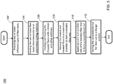
- FIG. 5 is a flow diagram of a process 100 using a blend of fibers to form chopped fiber perform mats for structural applications.
- the process starts with providing two or more different fiber tows (step 102) that will constitute the blended fiber content of the mat in desired weight proportions.
- Fiber tows may illustratively include thermoplastic, glass, carbon, and binder fibers.
- the various fiber tow are simultaneously fed to an automated cutting machine (step 104), and the resultant chopped blended fibers are coated with a binder and other additives and the blended fibers may be plasma treated (step 106).
- the coated and treated fibers are then moved to a treatment chamber to form a blended fiber mat (step 108).
- a veil mat is then applied to either side of the blended mat to form a consolidated mat (step 110).
- the consolidated mat is stored for later use as a charge pattern (step 112), and the process concludes.
Landscapes
- Engineering & Computer Science (AREA)
- Mechanical Engineering (AREA)
- Textile Engineering (AREA)
- Chemical & Material Sciences (AREA)
- Composite Materials (AREA)
- Physics & Mathematics (AREA)
- Plasma & Fusion (AREA)
- Toxicology (AREA)
- Health & Medical Sciences (AREA)
- Inorganic Chemistry (AREA)
- Reinforced Plastic Materials (AREA)
- Nonwoven Fabrics (AREA)
- Treatment Of Fiber Materials (AREA)
- Chemical Or Physical Treatment Of Fibers (AREA)
Claims (15)
- Procédé de formation d'un mat contenant une charge de fibres mélangées, comprenant les étapes suivantes :fournir deux ou plus de deux types différents d'étoupe de fibres ;acheminer lesdits deux ou plus de deux types de fibres simultanément jusqu'à une machine de coupe automatique dans le but de produire des fibres hachées qui forment la charge de fibres mélangées ;diriger un flux de gaz sous pression qui présente des composantes de flux à la fois rotative et verticale sur et dans un tube contenant les fibres hachées ;enduire les fibres hachées avec un liant et avec d'autres additifs ; etdéplacer les fibres mélangées enduites et traitées jusqu'à une chambre de traitement à l'intérieur de laquelle un ensemble de rouleaux est utilisé pour aplatir les fibres mélangées traitées sur une courroie mobile de manière à former un mat de fibres mélangées.
- Procédé selon la revendication 1, dans lequel lesdits deux ou plus de deux types de fibres différents comprennent au moins deux composants parmi le verre, le carbone, les polyimides, les polyaramides, les polyesters, les polyamides, et un liant, et/ou dans lequel les deux ou plus de deux types de fibres sont prévus de manière à obtenir un rapport en poids défini dans le mat de fibres mélangées, ou dans lequel le rapport de mélange des deux ou plus de deux types de fibres est le suivant : fibre thermoplastique de 25 % en poids à 80 % en poids, fibre de verre de renforcement de 0 % en poids à 70 % en poids, fibre de carbone de 0 % en poids à 70 % en poids, et un liant dans la gamme de 0 % en poids à 30 % en poids.
- Procédé selon la revendication 1, dans lequel ladite machine de coupe automatique est un hachoir rotatif vertical qui est disposé au-dessus d'une chambre à tourbillon.
- Procédé selon l'une quelconque des revendications 1 à 3, comprenant en outre l'ajout de charges de Curie.
- Procédé selon la revendication 1, comprenant en outre l'exposition des fibres hachées à un traitement au plasma, et plus particulièrement dans lequel l'exposition au plasma est réalisée à l'intérieur d'un réacteur à lit fluidisé, ou dans lequel le plasma est un plasma froid ou est un plasma chaud.
- Procédé selon la revendication 5, comprenant en outre la mise en place d'un mat en voile de part et d'autre du mat de fibres mélangées, et plus particulièrement dans lequel le mat en voile est constitué de fibres de verre, de fibres de carbone, de fibres thermoplastiques ou d'une combinaison de celles-ci.
- Procédé selon la revendication 6, comprenant en outre la consolidation du mat de fibres mélangées avec le mat en voile en utilisant un ensemble de rouleaux chauffés qui sont maintenus à la température de ramollissement d'un liant thermoplastique à la fois dans le mat en voile et dans le mat de fibres mélangées, et plus particulièrement dans lequel ledit liant se présente sous la forme d'une poudre, d'une fibre ou d'un solvant pulvérisé.
- Système pour former un mat de fibres mélangées, comprenant :deux ou plus de deux bobines de types différents d'étoupe de fibres ;un élément de coupe qui est configuré de manière à recevoir les deux ou plus de deux types d'étoupe de fibres dans le but de former des fibres hachées à partir desdites deux ou plus de deux bobines d'étoupe de fibres ;un tube qui est configuré de manière à recevoir la fibre hachée et dans lequel les fibres hachées sont soumises à un flux de gaz sous pression qui présente des composantes de flux à la fois rotative et verticale ;une courroie mobile qui est positionnée en dessous du tube de manière à collecter la fibre hachée qui sort du tube sous l'effet de la gravité ;un distributeur qui est positionné le long de la courroie mobile dans le but d'appliquer un liant sur la fibre hachée ; etune chambre de traitement qui reçoit la fibre hachée enduite du liant et qui comprend un ensemble de rouleaux destinés à aplatir la fibre hachée traitée sur la courroie mobile.
- Système selon la revendication 8, dans lequel lesdites deux ou plus de deux bobines de types différents d'étoupe de fibres sont constituées de verre, de carbone, de polyimides, de polyaramides, de polyesters et de polyamides, ainsi que de combinaisons de ceux-ci.
- Système selon la revendication 8, dans lequel le liant est appliqué à l'intérieur de la chambre de traitement.
- Système selon l'une quelconque des revendications 8 à 10, comprenant en outre un réservoir de particules qui se trouve en communication fluidique avec le flux de gaz.
- Système selon l'une quelconque des revendications 8 à 11, comprenant en outre un rail qui est incliné vers l'intérieur par rapport à la direction de déplacement de la courroie mobile de manière à pousser une partie de la fibre hachée en direction d'un axe médian de la courroie mobile.
- Système selon l'une quelconque des revendications 8 à 12, comprenant en outre une source d'énergie thermique, actinique ou de plasma qui est associée au distributeur dans le but de favoriser une réaction chimique entre le liant de l'additif et la fibre hachée.
- Système selon l'une quelconque des revendications 8 à 13, dans lequel la chambre de traitement comprend en outre une première section de chauffage qui durcit les fibres hachées traitées chimiquement, et une seconde section de refroidissement avant la sortie du mat de fibres mélangées hors de la chambre de traitement, ou dans lequel la chambre de traitement comprend en outre une courroie mobile supérieure.
- Système selon l'une quelconque des revendications 8 à 14, dans lequel le système de coupe comprend en outre une série de lames.
Applications Claiming Priority (2)
| Application Number | Priority Date | Filing Date | Title |
|---|---|---|---|
| US201662428035P | 2016-11-30 | 2016-11-30 | |
| PCT/US2017/063693 WO2018102404A1 (fr) | 2016-11-30 | 2017-11-29 | Formation de mat de fibres mélangées pour applications structurales |
Publications (3)
| Publication Number | Publication Date |
|---|---|
| EP3548237A1 EP3548237A1 (fr) | 2019-10-09 |
| EP3548237A4 EP3548237A4 (fr) | 2020-07-08 |
| EP3548237B1 true EP3548237B1 (fr) | 2022-01-05 |
Family
ID=62242629
Family Applications (1)
| Application Number | Title | Priority Date | Filing Date |
|---|---|---|---|
| EP17875916.3A Active EP3548237B1 (fr) | 2016-11-30 | 2017-11-29 | Formation de mat de fibres mélangées pour applications structurales |
Country Status (7)
| Country | Link |
|---|---|
| US (2) | US11072092B2 (fr) |
| EP (1) | EP3548237B1 (fr) |
| JP (1) | JP7164523B2 (fr) |
| CA (1) | CA3037052A1 (fr) |
| MX (1) | MX2019006321A (fr) |
| PT (1) | PT3548237T (fr) |
| WO (1) | WO2018102404A1 (fr) |
Families Citing this family (2)
| Publication number | Priority date | Publication date | Assignee | Title |
|---|---|---|---|---|
| US11642815B2 (en) * | 2016-11-30 | 2023-05-09 | Teijin Automotive Technologies, Inc. | Fiber mat formation for structural applications |
| JP7849788B2 (ja) * | 2021-09-13 | 2026-04-22 | 株式会社Subaru | 繊維強化熱可塑性樹脂の製造装置及び製造方法 |
Family Cites Families (21)
| Publication number | Priority date | Publication date | Assignee | Title |
|---|---|---|---|---|
| US2546266A (en) * | 1948-10-20 | 1951-03-27 | William J Kropp | Apparatus for making insulation batts and boards |
| US4863771A (en) | 1985-08-22 | 1989-09-05 | The Budd Company | Hollow fiber reinforced structure and method of making same |
| JPH0757820B2 (ja) * | 1987-12-19 | 1995-06-21 | トヨタ自動車株式会社 | 繊維強化樹脂組成物 |
| US5001172A (en) * | 1987-12-19 | 1991-03-19 | Kabushiki Kaisha Toyota Chuo Kenkyusho | Fiber reinforced plastics |
| EP0370512B1 (fr) | 1988-11-24 | 1995-03-01 | Kuraray Co., Ltd. | Nattes de fibres coupées et feuilles thermoplastiques |
| CA2102361C (fr) | 1993-07-23 | 2000-09-19 | F. Arthur Simmons | Methode de fabrication de matelas avec des materiaux fibreux en copeaux |
| US5972169A (en) | 1998-01-15 | 1999-10-26 | The Budd Company | Slurry preform system |
| US6029897A (en) * | 1998-03-19 | 2000-02-29 | N.V. Owens-Corning S.A. | Method of dispensing chopped reinforcement strand using a vortex nozzle |
| US7932193B2 (en) | 2004-02-17 | 2011-04-26 | Johns Manville | Coated mat products, laminates and method |
| US20070023975A1 (en) | 2005-08-01 | 2007-02-01 | Buckley Daniel T | Method for making three-dimensional preforms using anaerobic binders |
| FR2899146B1 (fr) * | 2006-03-28 | 2008-05-16 | Materials Technics Holding Sa | Procede pour la realisation d'un semi-produit composite renforce et estampable |
| US9663882B2 (en) | 2008-11-12 | 2017-05-30 | Thomas E. Haskett | Natural fiber nonwoven scouring material and methods of making |
| US20100143692A1 (en) | 2008-12-10 | 2010-06-10 | Ryan James P | Carbon and Glass Fiber Reinforced Composition |
| US9149834B2 (en) | 2011-07-22 | 2015-10-06 | Continental Structural Plastics, Inc. | Plasma treated molding composition and process for modifying a surface thereof |
| US10337129B2 (en) | 2012-05-01 | 2019-07-02 | Continental Structural Plastics, Inc. | Process of debundling carbon fiber tow and molding compositions containing such fibers |
| JP5979426B2 (ja) | 2012-07-12 | 2016-08-24 | 三菱レイヨン株式会社 | シートモールディングコンパウンド |
| JP5996320B2 (ja) * | 2012-08-01 | 2016-09-21 | 帝人株式会社 | ランダムマットの製造方法 |
| EP3077182A4 (fr) * | 2013-12-03 | 2017-08-09 | Continental Structural Plastics, Inc. | Source de plasma en ligne permettant l'introduction de morceaux d'un câble en fibres de carbone dispersées dans des compositions de moulage d'une chaîne de production de composés |
| US20150258762A1 (en) | 2014-03-14 | 2015-09-17 | Teijin Limited | Method of Producing Isotropic Random Mat for Forming Thermoplastic Composite Material |
| GB2528134A (en) | 2014-07-11 | 2016-01-13 | Colpac Ltd | Film lidded tray |
| WO2016057734A1 (fr) | 2014-10-08 | 2016-04-14 | Ocv Intellectual Capital, Llc | Composites thermoplastiques hybrides à fibres longues |
-
2017
- 2017-11-29 US US16/465,467 patent/US11072092B2/en active Active
- 2017-11-29 PT PT178759163T patent/PT3548237T/pt unknown
- 2017-11-29 JP JP2019527169A patent/JP7164523B2/ja active Active
- 2017-11-29 WO PCT/US2017/063693 patent/WO2018102404A1/fr not_active Ceased
- 2017-11-29 EP EP17875916.3A patent/EP3548237B1/fr active Active
- 2017-11-29 CA CA3037052A patent/CA3037052A1/fr active Pending
- 2017-11-29 MX MX2019006321A patent/MX2019006321A/es unknown
-
2021
- 2021-03-19 US US17/206,197 patent/US11717986B2/en active Active
Also Published As
| Publication number | Publication date |
|---|---|
| JP2020501032A (ja) | 2020-01-16 |
| JP7164523B2 (ja) | 2022-11-01 |
| MX2019006321A (es) | 2019-08-14 |
| EP3548237A1 (fr) | 2019-10-09 |
| US20210206024A1 (en) | 2021-07-08 |
| WO2018102404A8 (fr) | 2019-08-01 |
| CA3037052A1 (fr) | 2018-06-07 |
| US11072092B2 (en) | 2021-07-27 |
| EP3548237A4 (fr) | 2020-07-08 |
| PT3548237T (pt) | 2022-02-01 |
| US20200001503A1 (en) | 2020-01-02 |
| US11717986B2 (en) | 2023-08-08 |
| WO2018102404A1 (fr) | 2018-06-07 |
Similar Documents
| Publication | Publication Date | Title |
|---|---|---|
| KR101536502B1 (ko) | 강화 섬유 복합재료 | |
| KR101444631B1 (ko) | 랜덤 매트, 및 강화섬유 복합재료 | |
| EP2674447B1 (fr) | Objet moulé présentant un gradient d'épaisseur et son procédé de production | |
| CN104105743B (zh) | 无序毡和纤维增强复合材料 | |
| JP2011178890A (ja) | 炭素繊維複合材料 | |
| WO2014208626A1 (fr) | Mat aléatoire, article moulé en un matériau composite renforcé par des fibres, et mat de fibres de carbone | |
| JP2014030913A (ja) | ランダムマットの製造方法 | |
| US11717986B2 (en) | Blended fiber mat formation for structural applications | |
| US11066762B2 (en) | Process and system of debundling fiber tow for use in preform mats and molding compositions containing such fibers | |
| US11904502B2 (en) | Dispersed fiber mat formation | |
| Miller et al. | Impregnation techniques for thermoplastic matrix composites | |
| US20150258762A1 (en) | Method of Producing Isotropic Random Mat for Forming Thermoplastic Composite Material | |
| EP3548260B1 (fr) | Formation de mat de fibres pour applications structurales | |
| CA3012639C (fr) | Procede et systeme de demelage d'etoupe de fibre a utiliser dans des tapis de preforme, et compositions de moulage contenant de telles fibres | |
| Moradi | Development of High-Temperature and High-Performance Glass Fibre/PAEK Thermoplastic Prepregs |
Legal Events
| Date | Code | Title | Description |
|---|---|---|---|
| STAA | Information on the status of an ep patent application or granted ep patent |
Free format text: STATUS: THE INTERNATIONAL PUBLICATION HAS BEEN MADE |
|
| PUAI | Public reference made under article 153(3) epc to a published international application that has entered the european phase |
Free format text: ORIGINAL CODE: 0009012 |
|
| STAA | Information on the status of an ep patent application or granted ep patent |
Free format text: STATUS: REQUEST FOR EXAMINATION WAS MADE |
|
| 17P | Request for examination filed |
Effective date: 20190314 |
|
| AK | Designated contracting states |
Kind code of ref document: A1 Designated state(s): AL AT BE BG CH CY CZ DE DK EE ES FI FR GB GR HR HU IE IS IT LI LT LU LV MC MK MT NL NO PL PT RO RS SE SI SK SM TR |
|
| AX | Request for extension of the european patent |
Extension state: BA ME |
|
| DAV | Request for validation of the european patent (deleted) | ||
| DAX | Request for extension of the european patent (deleted) | ||
| A4 | Supplementary search report drawn up and despatched |
Effective date: 20200609 |
|
| RIC1 | Information provided on ipc code assigned before grant |
Ipc: D04H 1/732 20120101ALI20200603BHEP Ipc: B29C 70/50 20060101ALI20200603BHEP Ipc: B29B 7/90 20060101ALI20200603BHEP Ipc: B29B 13/08 20060101ALI20200603BHEP Ipc: D04H 1/58 20120101ALI20200603BHEP Ipc: D04H 1/4382 20120101ALI20200603BHEP Ipc: C08J 5/04 20060101ALI20200603BHEP Ipc: B29C 70/12 20060101ALI20200603BHEP Ipc: B29B 9/14 20060101AFI20200603BHEP Ipc: B29B 9/16 20060101ALI20200603BHEP |
|
| STAA | Information on the status of an ep patent application or granted ep patent |
Free format text: STATUS: EXAMINATION IS IN PROGRESS |
|
| 17Q | First examination report despatched |
Effective date: 20210122 |
|
| GRAP | Despatch of communication of intention to grant a patent |
Free format text: ORIGINAL CODE: EPIDOSNIGR1 |
|
| STAA | Information on the status of an ep patent application or granted ep patent |
Free format text: STATUS: GRANT OF PATENT IS INTENDED |
|
| RIC1 | Information provided on ipc code assigned before grant |
Ipc: B29B 7/90 20060101AFI20210521BHEP Ipc: B29B 13/08 20060101ALI20210521BHEP Ipc: B29C 70/12 20060101ALI20210521BHEP Ipc: B29C 70/50 20060101ALI20210521BHEP Ipc: D04H 1/4382 20120101ALI20210521BHEP Ipc: D04H 1/58 20120101ALI20210521BHEP Ipc: D04H 1/732 20120101ALI20210521BHEP Ipc: B29B 15/08 20060101ALN20210521BHEP |
|
| INTG | Intention to grant announced |
Effective date: 20210629 |
|
| GRAS | Grant fee paid |
Free format text: ORIGINAL CODE: EPIDOSNIGR3 |
|
| GRAJ | Information related to disapproval of communication of intention to grant by the applicant or resumption of examination proceedings by the epo deleted |
Free format text: ORIGINAL CODE: EPIDOSDIGR1 |
|
| GRAL | Information related to payment of fee for publishing/printing deleted |
Free format text: ORIGINAL CODE: EPIDOSDIGR3 |
|
| STAA | Information on the status of an ep patent application or granted ep patent |
Free format text: STATUS: EXAMINATION IS IN PROGRESS |
|
| REG | Reference to a national code |
Ref country code: DE Ref legal event code: R079 Ref document number: 602017052084 Country of ref document: DE Free format text: PREVIOUS MAIN CLASS: B29B0009140000 Ipc: B29B0007900000 |
|
| GRAP | Despatch of communication of intention to grant a patent |
Free format text: ORIGINAL CODE: EPIDOSNIGR1 |
|
| STAA | Information on the status of an ep patent application or granted ep patent |
Free format text: STATUS: GRANT OF PATENT IS INTENDED |
|
| INTC | Intention to grant announced (deleted) | ||
| RIC1 | Information provided on ipc code assigned before grant |
Ipc: B29B 15/08 20060101ALN20211004BHEP Ipc: D04H 1/732 20120101ALI20211004BHEP Ipc: D04H 1/58 20120101ALI20211004BHEP Ipc: D04H 1/4382 20120101ALI20211004BHEP Ipc: B29C 70/50 20060101ALI20211004BHEP Ipc: B29C 70/12 20060101ALI20211004BHEP Ipc: B29B 13/08 20060101ALI20211004BHEP Ipc: B29B 7/90 20060101AFI20211004BHEP |
|
| INTG | Intention to grant announced |
Effective date: 20211029 |
|
| GRAA | (expected) grant |
Free format text: ORIGINAL CODE: 0009210 |
|
| STAA | Information on the status of an ep patent application or granted ep patent |
Free format text: STATUS: THE PATENT HAS BEEN GRANTED |
|
| AK | Designated contracting states |
Kind code of ref document: B1 Designated state(s): AL AT BE BG CH CY CZ DE DK EE ES FI FR GB GR HR HU IE IS IT LI LT LU LV MC MK MT NL NO PL PT RO RS SE SI SK SM TR |
|
| REG | Reference to a national code |
Ref country code: GB Ref legal event code: FG4D |
|
| REG | Reference to a national code |
Ref country code: CH Ref legal event code: EP |
|
| REG | Reference to a national code |
Ref country code: AT Ref legal event code: REF Ref document number: 1460126 Country of ref document: AT Kind code of ref document: T Effective date: 20220115 |
|
| REG | Reference to a national code |
Ref country code: DE Ref legal event code: R096 Ref document number: 602017052084 Country of ref document: DE |
|
| REG | Reference to a national code |
Ref country code: PT Ref legal event code: SC4A Ref document number: 3548237 Country of ref document: PT Date of ref document: 20220201 Kind code of ref document: T Free format text: AVAILABILITY OF NATIONAL TRANSLATION Effective date: 20220125 |
|
| REG | Reference to a national code |
Ref country code: IE Ref legal event code: FG4D |
|
| REG | Reference to a national code |
Ref country code: LT Ref legal event code: MG9D |
|
| REG | Reference to a national code |
Ref country code: NL Ref legal event code: MP Effective date: 20220105 |
|
| REG | Reference to a national code |
Ref country code: AT Ref legal event code: MK05 Ref document number: 1460126 Country of ref document: AT Kind code of ref document: T Effective date: 20220105 |
|
| PG25 | Lapsed in a contracting state [announced via postgrant information from national office to epo] |
Ref country code: NL Free format text: LAPSE BECAUSE OF FAILURE TO SUBMIT A TRANSLATION OF THE DESCRIPTION OR TO PAY THE FEE WITHIN THE PRESCRIBED TIME-LIMIT Effective date: 20220105 |
|
| PG25 | Lapsed in a contracting state [announced via postgrant information from national office to epo] |
Ref country code: SE Free format text: LAPSE BECAUSE OF FAILURE TO SUBMIT A TRANSLATION OF THE DESCRIPTION OR TO PAY THE FEE WITHIN THE PRESCRIBED TIME-LIMIT Effective date: 20220105 Ref country code: RS Free format text: LAPSE BECAUSE OF FAILURE TO SUBMIT A TRANSLATION OF THE DESCRIPTION OR TO PAY THE FEE WITHIN THE PRESCRIBED TIME-LIMIT Effective date: 20220105 Ref country code: NO Free format text: LAPSE BECAUSE OF FAILURE TO SUBMIT A TRANSLATION OF THE DESCRIPTION OR TO PAY THE FEE WITHIN THE PRESCRIBED TIME-LIMIT Effective date: 20220405 Ref country code: LT Free format text: LAPSE BECAUSE OF FAILURE TO SUBMIT A TRANSLATION OF THE DESCRIPTION OR TO PAY THE FEE WITHIN THE PRESCRIBED TIME-LIMIT Effective date: 20220105 Ref country code: HR Free format text: LAPSE BECAUSE OF FAILURE TO SUBMIT A TRANSLATION OF THE DESCRIPTION OR TO PAY THE FEE WITHIN THE PRESCRIBED TIME-LIMIT Effective date: 20220105 Ref country code: ES Free format text: LAPSE BECAUSE OF FAILURE TO SUBMIT A TRANSLATION OF THE DESCRIPTION OR TO PAY THE FEE WITHIN THE PRESCRIBED TIME-LIMIT Effective date: 20220105 Ref country code: BG Free format text: LAPSE BECAUSE OF FAILURE TO SUBMIT A TRANSLATION OF THE DESCRIPTION OR TO PAY THE FEE WITHIN THE PRESCRIBED TIME-LIMIT Effective date: 20220405 |
|
| PG25 | Lapsed in a contracting state [announced via postgrant information from national office to epo] |
Ref country code: PL Free format text: LAPSE BECAUSE OF FAILURE TO SUBMIT A TRANSLATION OF THE DESCRIPTION OR TO PAY THE FEE WITHIN THE PRESCRIBED TIME-LIMIT Effective date: 20220105 Ref country code: LV Free format text: LAPSE BECAUSE OF FAILURE TO SUBMIT A TRANSLATION OF THE DESCRIPTION OR TO PAY THE FEE WITHIN THE PRESCRIBED TIME-LIMIT Effective date: 20220105 Ref country code: GR Free format text: LAPSE BECAUSE OF FAILURE TO SUBMIT A TRANSLATION OF THE DESCRIPTION OR TO PAY THE FEE WITHIN THE PRESCRIBED TIME-LIMIT Effective date: 20220406 Ref country code: FI Free format text: LAPSE BECAUSE OF FAILURE TO SUBMIT A TRANSLATION OF THE DESCRIPTION OR TO PAY THE FEE WITHIN THE PRESCRIBED TIME-LIMIT Effective date: 20220105 Ref country code: AT Free format text: LAPSE BECAUSE OF FAILURE TO SUBMIT A TRANSLATION OF THE DESCRIPTION OR TO PAY THE FEE WITHIN THE PRESCRIBED TIME-LIMIT Effective date: 20220105 |
|
| PG25 | Lapsed in a contracting state [announced via postgrant information from national office to epo] |
Ref country code: IS Free format text: LAPSE BECAUSE OF FAILURE TO SUBMIT A TRANSLATION OF THE DESCRIPTION OR TO PAY THE FEE WITHIN THE PRESCRIBED TIME-LIMIT Effective date: 20220505 |
|
| REG | Reference to a national code |
Ref country code: DE Ref legal event code: R097 Ref document number: 602017052084 Country of ref document: DE |
|
| PG25 | Lapsed in a contracting state [announced via postgrant information from national office to epo] |
Ref country code: SM Free format text: LAPSE BECAUSE OF FAILURE TO SUBMIT A TRANSLATION OF THE DESCRIPTION OR TO PAY THE FEE WITHIN THE PRESCRIBED TIME-LIMIT Effective date: 20220105 Ref country code: SK Free format text: LAPSE BECAUSE OF FAILURE TO SUBMIT A TRANSLATION OF THE DESCRIPTION OR TO PAY THE FEE WITHIN THE PRESCRIBED TIME-LIMIT Effective date: 20220105 Ref country code: RO Free format text: LAPSE BECAUSE OF FAILURE TO SUBMIT A TRANSLATION OF THE DESCRIPTION OR TO PAY THE FEE WITHIN THE PRESCRIBED TIME-LIMIT Effective date: 20220105 Ref country code: EE Free format text: LAPSE BECAUSE OF FAILURE TO SUBMIT A TRANSLATION OF THE DESCRIPTION OR TO PAY THE FEE WITHIN THE PRESCRIBED TIME-LIMIT Effective date: 20220105 Ref country code: DK Free format text: LAPSE BECAUSE OF FAILURE TO SUBMIT A TRANSLATION OF THE DESCRIPTION OR TO PAY THE FEE WITHIN THE PRESCRIBED TIME-LIMIT Effective date: 20220105 |
|
| PLBE | No opposition filed within time limit |
Free format text: ORIGINAL CODE: 0009261 |
|
| STAA | Information on the status of an ep patent application or granted ep patent |
Free format text: STATUS: NO OPPOSITION FILED WITHIN TIME LIMIT |
|
| PG25 | Lapsed in a contracting state [announced via postgrant information from national office to epo] |
Ref country code: AL Free format text: LAPSE BECAUSE OF FAILURE TO SUBMIT A TRANSLATION OF THE DESCRIPTION OR TO PAY THE FEE WITHIN THE PRESCRIBED TIME-LIMIT Effective date: 20220105 |
|
| 26N | No opposition filed |
Effective date: 20221006 |
|
| PG25 | Lapsed in a contracting state [announced via postgrant information from national office to epo] |
Ref country code: SI Free format text: LAPSE BECAUSE OF FAILURE TO SUBMIT A TRANSLATION OF THE DESCRIPTION OR TO PAY THE FEE WITHIN THE PRESCRIBED TIME-LIMIT Effective date: 20220105 |
|
| P01 | Opt-out of the competence of the unified patent court (upc) registered |
Effective date: 20230508 |
|
| PG25 | Lapsed in a contracting state [announced via postgrant information from national office to epo] |
Ref country code: MC Free format text: LAPSE BECAUSE OF FAILURE TO SUBMIT A TRANSLATION OF THE DESCRIPTION OR TO PAY THE FEE WITHIN THE PRESCRIBED TIME-LIMIT Effective date: 20220105 |
|
| REG | Reference to a national code |
Ref country code: CH Ref legal event code: PL |
|
| REG | Reference to a national code |
Ref country code: DE Ref legal event code: R081 Ref document number: 602017052084 Country of ref document: DE Owner name: TEIJIN AUTOMOTIVE TECHNOLOGIES, INC., AUBURN H, US Free format text: FORMER OWNER: CONTINENTAL STRUCTURAL PLASTICS, INC., AUBURN HILLS, MI, US |
|
| GBPC | Gb: european patent ceased through non-payment of renewal fee |
Effective date: 20221129 |
|
| REG | Reference to a national code |
Ref country code: BE Ref legal event code: MM Effective date: 20221130 |
|
| PG25 | Lapsed in a contracting state [announced via postgrant information from national office to epo] |
Ref country code: LI Free format text: LAPSE BECAUSE OF NON-PAYMENT OF DUE FEES Effective date: 20221130 Ref country code: IT Free format text: LAPSE BECAUSE OF FAILURE TO SUBMIT A TRANSLATION OF THE DESCRIPTION OR TO PAY THE FEE WITHIN THE PRESCRIBED TIME-LIMIT Effective date: 20220105 Ref country code: CH Free format text: LAPSE BECAUSE OF NON-PAYMENT OF DUE FEES Effective date: 20221130 |
|
| PG25 | Lapsed in a contracting state [announced via postgrant information from national office to epo] |
Ref country code: LU Free format text: LAPSE BECAUSE OF NON-PAYMENT OF DUE FEES Effective date: 20221129 |
|
| PG25 | Lapsed in a contracting state [announced via postgrant information from national office to epo] |
Ref country code: IE Free format text: LAPSE BECAUSE OF NON-PAYMENT OF DUE FEES Effective date: 20221129 Ref country code: GB Free format text: LAPSE BECAUSE OF NON-PAYMENT OF DUE FEES Effective date: 20221129 |
|
| PG25 | Lapsed in a contracting state [announced via postgrant information from national office to epo] |
Ref country code: BE Free format text: LAPSE BECAUSE OF NON-PAYMENT OF DUE FEES Effective date: 20221130 |
|
| PG25 | Lapsed in a contracting state [announced via postgrant information from national office to epo] |
Ref country code: HU Free format text: LAPSE BECAUSE OF FAILURE TO SUBMIT A TRANSLATION OF THE DESCRIPTION OR TO PAY THE FEE WITHIN THE PRESCRIBED TIME-LIMIT; INVALID AB INITIO Effective date: 20171129 |
|
| PG25 | Lapsed in a contracting state [announced via postgrant information from national office to epo] |
Ref country code: CY Free format text: LAPSE BECAUSE OF FAILURE TO SUBMIT A TRANSLATION OF THE DESCRIPTION OR TO PAY THE FEE WITHIN THE PRESCRIBED TIME-LIMIT Effective date: 20220105 |
|
| PG25 | Lapsed in a contracting state [announced via postgrant information from national office to epo] |
Ref country code: MK Free format text: LAPSE BECAUSE OF FAILURE TO SUBMIT A TRANSLATION OF THE DESCRIPTION OR TO PAY THE FEE WITHIN THE PRESCRIBED TIME-LIMIT Effective date: 20220105 |
|
| PG25 | Lapsed in a contracting state [announced via postgrant information from national office to epo] |
Ref country code: TR Free format text: LAPSE BECAUSE OF FAILURE TO SUBMIT A TRANSLATION OF THE DESCRIPTION OR TO PAY THE FEE WITHIN THE PRESCRIBED TIME-LIMIT Effective date: 20220105 |
|
| PG25 | Lapsed in a contracting state [announced via postgrant information from national office to epo] |
Ref country code: MT Free format text: LAPSE BECAUSE OF FAILURE TO SUBMIT A TRANSLATION OF THE DESCRIPTION OR TO PAY THE FEE WITHIN THE PRESCRIBED TIME-LIMIT Effective date: 20220105 |
|
| PGFP | Annual fee paid to national office [announced via postgrant information from national office to epo] |
Ref country code: PT Payment date: 20241121 Year of fee payment: 8 |
|
| PGFP | Annual fee paid to national office [announced via postgrant information from national office to epo] |
Ref country code: DE Payment date: 20241121 Year of fee payment: 8 |
|
| PGFP | Annual fee paid to national office [announced via postgrant information from national office to epo] |
Ref country code: FR Payment date: 20241128 Year of fee payment: 8 |
|
| PGFP | Annual fee paid to national office [announced via postgrant information from national office to epo] |
Ref country code: CZ Payment date: 20241125 Year of fee payment: 8 |