EP3548362B1 - Redundante lenkkontrollen für automatisiertes fahren - Google Patents
Redundante lenkkontrollen für automatisiertes fahren Download PDFInfo
- Publication number
- EP3548362B1 EP3548362B1 EP17784803.3A EP17784803A EP3548362B1 EP 3548362 B1 EP3548362 B1 EP 3548362B1 EP 17784803 A EP17784803 A EP 17784803A EP 3548362 B1 EP3548362 B1 EP 3548362B1
- Authority
- EP
- European Patent Office
- Prior art keywords
- hydraulic motor
- fluid
- control module
- brake
- brake control
- Prior art date
- Legal status (The legal status is an assumption and is not a legal conclusion. Google has not performed a legal analysis and makes no representation as to the accuracy of the status listed.)
- Active
Links
Images

Classifications
-
- B—PERFORMING OPERATIONS; TRANSPORTING
- B62—LAND VEHICLES FOR TRAVELLING OTHERWISE THAN ON RAILS
- B62D—MOTOR VEHICLES; TRAILERS
- B62D11/00—Steering non-deflectable wheels; Steering endless tracks or the like
- B62D11/02—Steering non-deflectable wheels; Steering endless tracks or the like by differentially driving ground-engaging elements on opposite vehicle sides
-
- B—PERFORMING OPERATIONS; TRANSPORTING
- B62—LAND VEHICLES FOR TRAVELLING OTHERWISE THAN ON RAILS
- B62D—MOTOR VEHICLES; TRAILERS
- B62D5/00—Power-assisted or power-driven steering
- B62D5/04—Power-assisted or power-driven steering electrical, e.g. using an electric servo-motor connected to, or forming part of, the steering gear
- B62D5/0457—Power-assisted or power-driven steering electrical, e.g. using an electric servo-motor connected to, or forming part of, the steering gear characterised by control features of the drive means as such
- B62D5/0481—Power-assisted or power-driven steering electrical, e.g. using an electric servo-motor connected to, or forming part of, the steering gear characterised by control features of the drive means as such monitoring the steering system, e.g. failures
- B62D5/0484—Power-assisted or power-driven steering electrical, e.g. using an electric servo-motor connected to, or forming part of, the steering gear characterised by control features of the drive means as such monitoring the steering system, e.g. failures for reaction to failures, e.g. limp home
-
- B—PERFORMING OPERATIONS; TRANSPORTING
- B60—VEHICLES IN GENERAL
- B60T—VEHICLE BRAKE CONTROL SYSTEMS OR PARTS THEREOF; BRAKE CONTROL SYSTEMS OR PARTS THEREOF, IN GENERAL; ARRANGEMENT OF BRAKING ELEMENTS ON VEHICLES IN GENERAL; PORTABLE DEVICES FOR PREVENTING UNWANTED MOVEMENT OF VEHICLES; VEHICLE MODIFICATIONS TO FACILITATE COOLING OF BRAKES
- B60T1/00—Arrangements of braking elements, i.e. of those parts where braking effect occurs specially for vehicles
- B60T1/02—Arrangements of braking elements, i.e. of those parts where braking effect occurs specially for vehicles acting by retarding wheels
- B60T1/10—Arrangements of braking elements, i.e. of those parts where braking effect occurs specially for vehicles acting by retarding wheels by utilising wheel movement for accumulating energy, e.g. driving air compressors
-
- B—PERFORMING OPERATIONS; TRANSPORTING
- B60—VEHICLES IN GENERAL
- B60T—VEHICLE BRAKE CONTROL SYSTEMS OR PARTS THEREOF; BRAKE CONTROL SYSTEMS OR PARTS THEREOF, IN GENERAL; ARRANGEMENT OF BRAKING ELEMENTS ON VEHICLES IN GENERAL; PORTABLE DEVICES FOR PREVENTING UNWANTED MOVEMENT OF VEHICLES; VEHICLE MODIFICATIONS TO FACILITATE COOLING OF BRAKES
- B60T11/00—Transmitting braking action from initiating means to ultimate brake actuator without power assistance or drive or where such assistance or drive is irrelevant
- B60T11/10—Transmitting braking action from initiating means to ultimate brake actuator without power assistance or drive or where such assistance or drive is irrelevant transmitting by fluid means, e.g. hydraulic
- B60T11/103—Transmitting braking action from initiating means to ultimate brake actuator without power assistance or drive or where such assistance or drive is irrelevant transmitting by fluid means, e.g. hydraulic in combination with other control devices
-
- B—PERFORMING OPERATIONS; TRANSPORTING
- B60—VEHICLES IN GENERAL
- B60T—VEHICLE BRAKE CONTROL SYSTEMS OR PARTS THEREOF; BRAKE CONTROL SYSTEMS OR PARTS THEREOF, IN GENERAL; ARRANGEMENT OF BRAKING ELEMENTS ON VEHICLES IN GENERAL; PORTABLE DEVICES FOR PREVENTING UNWANTED MOVEMENT OF VEHICLES; VEHICLE MODIFICATIONS TO FACILITATE COOLING OF BRAKES
- B60T13/00—Transmitting braking action from initiating means to ultimate brake actuator with power assistance or drive; Brake systems incorporating such transmitting means, e.g. air-pressure brake systems
- B60T13/02—Transmitting braking action from initiating means to ultimate brake actuator with power assistance or drive; Brake systems incorporating such transmitting means, e.g. air-pressure brake systems with mechanical assistance or drive
- B60T13/04—Transmitting braking action from initiating means to ultimate brake actuator with power assistance or drive; Brake systems incorporating such transmitting means, e.g. air-pressure brake systems with mechanical assistance or drive by spring or weight
-
- B—PERFORMING OPERATIONS; TRANSPORTING
- B60—VEHICLES IN GENERAL
- B60T—VEHICLE BRAKE CONTROL SYSTEMS OR PARTS THEREOF; BRAKE CONTROL SYSTEMS OR PARTS THEREOF, IN GENERAL; ARRANGEMENT OF BRAKING ELEMENTS ON VEHICLES IN GENERAL; PORTABLE DEVICES FOR PREVENTING UNWANTED MOVEMENT OF VEHICLES; VEHICLE MODIFICATIONS TO FACILITATE COOLING OF BRAKES
- B60T13/00—Transmitting braking action from initiating means to ultimate brake actuator with power assistance or drive; Brake systems incorporating such transmitting means, e.g. air-pressure brake systems
- B60T13/10—Transmitting braking action from initiating means to ultimate brake actuator with power assistance or drive; Brake systems incorporating such transmitting means, e.g. air-pressure brake systems with fluid assistance, drive, or release
- B60T13/66—Electrical control in fluid-pressure brake systems
- B60T13/68—Electrical control in fluid-pressure brake systems by electrically-controlled valves
- B60T13/686—Electrical control in fluid-pressure brake systems by electrically-controlled valves in hydraulic systems or parts thereof
-
- B—PERFORMING OPERATIONS; TRANSPORTING
- B60—VEHICLES IN GENERAL
- B60T—VEHICLE BRAKE CONTROL SYSTEMS OR PARTS THEREOF; BRAKE CONTROL SYSTEMS OR PARTS THEREOF, IN GENERAL; ARRANGEMENT OF BRAKING ELEMENTS ON VEHICLES IN GENERAL; PORTABLE DEVICES FOR PREVENTING UNWANTED MOVEMENT OF VEHICLES; VEHICLE MODIFICATIONS TO FACILITATE COOLING OF BRAKES
- B60T7/00—Brake-action initiating means
- B60T7/12—Brake-action initiating means for automatic initiation; for initiation not subject to will of driver or passenger
-
- B—PERFORMING OPERATIONS; TRANSPORTING
- B62—LAND VEHICLES FOR TRAVELLING OTHERWISE THAN ON RAILS
- B62D—MOTOR VEHICLES; TRAILERS
- B62D11/00—Steering non-deflectable wheels; Steering endless tracks or the like
- B62D11/001—Steering non-deflectable wheels; Steering endless tracks or the like control systems
- B62D11/003—Electric or electronic control systems
-
- B—PERFORMING OPERATIONS; TRANSPORTING
- B62—LAND VEHICLES FOR TRAVELLING OTHERWISE THAN ON RAILS
- B62D—MOTOR VEHICLES; TRAILERS
- B62D5/00—Power-assisted or power-driven steering
- B62D5/06—Power-assisted or power-driven steering fluid, i.e. using a pressurised fluid for most or all the force required for steering a vehicle
- B62D5/07—Supply of pressurised fluid for steering also supplying other consumers ; control thereof
-
- B—PERFORMING OPERATIONS; TRANSPORTING
- B62—LAND VEHICLES FOR TRAVELLING OTHERWISE THAN ON RAILS
- B62D—MOTOR VEHICLES; TRAILERS
- B62D9/00—Steering deflectable wheels not otherwise provided for
- B62D9/002—Steering deflectable wheels not otherwise provided for combined with means for differentially distributing power on the deflectable wheels during cornering
-
- F—MECHANICAL ENGINEERING; LIGHTING; HEATING; WEAPONS; BLASTING
- F16—ENGINEERING ELEMENTS AND UNITS; GENERAL MEASURES FOR PRODUCING AND MAINTAINING EFFECTIVE FUNCTIONING OF MACHINES OR INSTALLATIONS; THERMAL INSULATION IN GENERAL
- F16D—COUPLINGS FOR TRANSMITTING ROTATION; CLUTCHES; BRAKES
- F16D61/00—Brakes with means for making the energy absorbed available for use
-
- B—PERFORMING OPERATIONS; TRANSPORTING
- B60—VEHICLES IN GENERAL
- B60T—VEHICLE BRAKE CONTROL SYSTEMS OR PARTS THEREOF; BRAKE CONTROL SYSTEMS OR PARTS THEREOF, IN GENERAL; ARRANGEMENT OF BRAKING ELEMENTS ON VEHICLES IN GENERAL; PORTABLE DEVICES FOR PREVENTING UNWANTED MOVEMENT OF VEHICLES; VEHICLE MODIFICATIONS TO FACILITATE COOLING OF BRAKES
- B60T2260/00—Interaction of vehicle brake system with other systems
- B60T2260/02—Active Steering, Steer-by-Wire
Definitions
- the invention relates generally to a steering system which is controlled by a redundant brake control system, for an autonomous driving vehicle.
- Vehicles with autonomous driving capabilities are becoming increasingly common. Some vehicles are fully autonomous, and do not require the input of a driver. These types of vehicle may have different modes of operation, where in one mode of operation, the driver controls the vehicle, and in another mode of operation, the vehicle is operating in a fully autonomous driving mode, with no input from the driver. Furthermore, there are also vehicles which are used for transporting passengers or cargo, but do not have a driver, and are designed such that a driver never provides any type of input to control the vehicle. Therefore the operation of the vehicle, such as steering, acceleration, braking, and parking, are controlled by various components, such as control modules and the like.
- the control modules receive input from various devices, such as sensors, GPS, and the like, to determine what operations are to be performed based on certain parameters such as local speed limits, oncoming traffic signals, and the speed and location of nearby vehicles.
- various devices such as sensors, GPS, and the like
- the automated driving system of the vehicle With more vehicles being fully operational without the use of driver input, there is a need for the automated driving system of the vehicle to have various redundancies to ensure safe handling of the vehicle in fallback conditions.
- the present invention is a redundant steering system which is powered by components of a redundant brake system, where the redundant steering system is activated upon failure of the primary steering system.
- the present invention is a brake system operable for controlling a steering system, which includes a primary brake control module for controlling fluid pressure in the brake system, a secondary brake control module for controlling fluid pressure in the brake system independently of the primary brake control module, and a plurality of brake units controlled by the primary brake control module or the secondary brake control module, where the brake units are used for decelerating the vehicle.
- There is at least one hydraulic motor and the fluid pressure in the hydraulic motor is controlled by the secondary brake control module.
- a steering system is used for steering a plurality of wheels of the vehicle, and the hydraulic motor is connected to a component of the steering system, such as a steering knuckle.
- a first fluid conduit is connected to and in fluid communication with the hydraulic motor and the secondary brake control module, and a second fluid conduit connected to and in fluid communication with the hydraulic motor and the secondary brake control module.
- a virtual driver is in electrical communication with the primary brake control module and the secondary brake control module.
- the secondary brake control module controls the brake units based on input from the virtual driver when the secondary brake control module is active.
- fluid is pumped from the secondary brake control module through the first fluid conduit to the hydraulic motor, and fluid is pumped from the hydraulic motor through the second fluid conduit to the secondary brake control module.
- fluid is pumped from the secondary brake control module through the second fluid conduit to the hydraulic motor, and fluid is pumped from the hydraulic motor through the first fluid conduit to the secondary brake control module.
- the wheels are configured for making a right-hand turn
- the wheels are configured for making a left-hand turn.
- the wheels are configured to make a right-hand turn when the secondary brake control module operates the hydraulic motor during the first mode of operation, and the wheels are configured to make a left-hand turn when the secondary brake control module operates the hydraulic motor during the second mode of operation.
- the secondary brake control module is active and controls the fluid pressure in the secondary brake system when there is a malfunction in the primary brake system.
- first hydraulic motor connected to a first component of the steering system, the first hydraulic motor being connected to and in fluid communication with the first fluid conduit, and a second hydraulic motor connected to a second component of the steering system, the second hydraulic motor being connected to and in fluid communication with the second fluid conduit.
- first mode of operation fluid is pumped from the secondary brake control module through the first fluid conduit to the first hydraulic motor to actuate the first hydraulic motor, and fluid is pumped from the second hydraulic motor, through the second fluid conduit, to the secondary brake control module.
- second mode of operation fluid is pumped from the secondary brake control module through the second fluid conduit to the second hydraulic motor to actuate the second hydraulic motor, and fluid is pumped from the first hydraulic motor, through the first fluid conduit, to the secondary brake control module.
- the brake system operable for controlling the steering system also includes a first brake unit and a second brake unit, both of which are part of the plurality of brake units.
- the brake system also includes a second brake conduit connected to and in fluid communication with the second fluid conduit, the second brake conduit also connected to and in fluid communication with the secondary brake control module and the second brake unit such that during the second mode of operation, fluid is pumped from the secondary brake control module through the second fluid conduit to the second hydraulic motor to actuate the second hydraulic motor, and through the second brake conduit to actuate the second brake unit.
- first hydraulic motor and the first brake unit are actuated simultaneously during the first mode of operation, and the second hydraulic motor and the second brake unit are actuated simultaneously during the second mode of operation.
- the brake system which is operable for controlling the steering system also includes a third mode of operation.
- fluid is pumped from the secondary brake control module through the first fluid conduit to the first hydraulic motor to actuate the first hydraulic motor, and through the first brake conduit to actuate the first brake unit, and fluid is also pumped from the secondary brake control module through the second fluid conduit to the second hydraulic motor to actuate the second hydraulic motor, and through the second brake conduit to actuate the second brake unit.
- the first hydraulic motor, the first brake unit, the second hydraulic motor, and the second brake unit are actuated simultaneously, such that the vehicle decelerates, and moves in a substantially straight direction.
- FIG. 1 A diagram of a braking system used to provide redundant controls for a steering system according to a first embodiment of the present invention is shown in Figure 1 , generally at 10.
- the system 10 includes a body electronic control unit (ECU) 12 in electrical communication with a Fluid Level Indicator (FLI) 14 connected to a first, or primary, brake control module (BCM) 16.
- the BCM 16 is in fluid communication with a reservoir 18, and the reservoir 18 is also in fluid communication with a second, or backup BCM 20.
- FLI 22 connected to the reservoir 18, and in electrical communication with the backup BCM 20.
- Power is supplied to the primary BCM 16 by a first power supply 24, and there is a brake pedal 26 mechanically connected to the primary BCM 16.
- the primary BCM 16 is in fluid communication with one or more brake units 28a,28b,28c,28d such that when the operator, or driver, of the vehicle applies force to the brake pedal 26, the primary BCM 16 detects the force applied to the brake pedal 26, which results in the actuation of one or more brake units 28a,28b,28c,28d.
- the change in position of the brake pedal 26 is detected by the primary BCM 16 through the use of a position sensor 30.
- the position sensor 30 is also in electrical communication with the backup BCM 20, such that the backup BCM 20 also receives a signal from the position sensor 30 indicating the position of the brake pedal 26.
- the primary BCM 16 is also in electrical communication and fluid communication with the backup BCM 20, and the primary BCM 16 is also in fluid communication with a pressure sensor 30a.
- the backup BCM 20 is also in fluid communication with the first two brake unit units 28a,28b and also actuates a bi-directional hydraulic motor 32, which is part of a steering system, shown generally at 50.
- the system 10 also includes several components to perform a parking brake function.
- the primary BCM 16 and backup BCM 20 are both in electrical communication with a first parking brake unit 36a and a second parking brake unit 36b.
- EPB electronic parking brake
- the system 10 may also be controlled by a virtual driver, when the vehicle is operating in an autonomous driving mode.
- the virtual driver is shown in Figure 1 , generally at 38, where the virtual driver 38 is in electrical communication with both BCM 16,20.
- the virtual driver 38 includes a primary controller 40 and a secondary, or redundant, controller 42.
- the primary controller 40 is powered by the first power supply 24, and there is a second power supply 44 which supplies power to the secondary controller 42, as well as the backup BCM 20, and the position sensor 30.
- IMU Inertial Measurement Unit
- wheel speed sensors 48a,48b,48c,48d used to detect the speed of each wheel of the vehicle.
- the steering system 50 includes a plurality of linkage arms 52a,52b,52c,52d.
- the motor 32 is connected to a component of the steering system 50, and used to control the steering system 50 when the vehicle is operating in an autonomous driving mode, and there is a failure somewhere in the primary controls of the steering system 50.
- the component is a steering knuckle 54a, but it is within the scope of the invention that the motor 32 may be attached to other components of the steering system 50 to control the steering system 50.
- the first linkage arm 54a is fixedly connected to the first steering knuckle 54a, and there is a first wheel 56a mounted to the first steering knuckle 54a.
- a second linkage arm 52b is pivotally connected to the first linkage arm 52a and a steering rack 58 which is in mesh with a pinion gear 60.
- the fourth linkage arm 52d is fixedly connected to a second steering knuckle 54b, and there is a second wheel 56b mounted to the second steering knuckle 54b.
- first fluid conduit 62a and a second fluid conduit 62b are connected to and in fluid communication with the backup BCM 20 and the motor 32.
- the driver rotates the steering wheel (not shown) such that other various steering components rotate the pinion gear 60 to move the steering rack 58, which moves the linkage arms 52a,52b and rotates the first steering knuckle 54a and first wheel 56a about a first axis 64. Movement of the steering rack 58 also moves the linkage arms 52c,52d and rotates the second steering knuckle 54b and second wheel 56b about a second axis 66.
- the knuckles 54a,54b and wheels 56a,56b are able to be rotated in a first direction, as indicated by a first arrow 68, to configure the wheels 56a,56b for making a right-hand turn, and the knuckles 54a,54b and wheels 56a,56b are able to be rotated in a second direction, as indicated by a second arrow 70, to configure the wheels 56a,56b for making a left-hand turn.
- the vehicle includes a redundancy operating mode, which is used to control the steering system 50 when there is a failure elsewhere in the vehicle. In the redundancy operating mode, instead of the pinion gear 60 being rotated to move the steering rack 58, the motor 32 is actuated to rotate the first steering knuckle 54a.
- the backup BCM 20 is used to transfer fluid through one of the fluid conduits 62a,62b to control the motor 32.
- the backup BCM 20 is able to control the motor 32 in two modes of operation.
- the backup BCM 20 pumps fluid through the first fluid conduit 62a. Because the motor 32 pumps fluid, the fluid pumped by the motor 32 enters the second fluid conduit 62b such that the second fluid conduit 62b acts as a return conduit, where fluid exiting the motor 32 flows back towards the backup BCM 20.
- the backup BCM 20 pumps fluid through the second fluid conduit 62b. Because the motor 32 in Figure 1 is a bi-directional hydraulic motor 32, fluid entering the motor 32 from the second fluid conduit 62b, is pumped out of the motor 32 into the first fluid conduit 62a, such that the first fluid conduit 62a acts as a return conduit, where fluid exiting the motor 32 flows back towards the backup BCM 20.
- the motor 32 is a bi-directional hydraulic motor 32, there is a pre-determined amount of fluid needed in the system 10, since the fluid is pumped between the backup BCM 20 and the motor 32 during the two modes of operation.
- the motor 32 is actuated to rotate the knuckles 54a,54b and wheels 56a,56b in the first direction 68, to configure the wheels 56a,56b for making a right-hand turn.
- the knuckles 54a,54b and wheels 56a,56b are rotated in the second direction 70, to configure the wheels 56a,56b for making a left-hand turn.
- the redundancy operating mode is active when there is some failure that occurs when the vehicle is operating in the autonomous driving mode, and the primary controls of the steering system 50 are not working, which may result from a failure in the first power supply 24.
- the redundant controller 42 of the virtual driver 38 is used to control the backup BCM 20, and therefore the steering system 50 when the vehicle is operating in the redundancy operating mode. This helps to ensure that even if there is a failure during the autonomous driving mode, control of the vehicle may still be maintained.
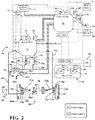
- FIG. 2 Another embodiment of the present invention is shown in Figure 2 , with like numbers referring to like elements.
- there is no bi-directional hydraulic motor 32 but rather there is a first uni-directional hydraulic motor 72a attached to the first steering knuckle 54a, and a second uni-directional hydraulic motor 72b attached to the second steering knuckle 54b.
- the first fluid conduit 62a is connected to and in fluid communication with the first uni-directional hydraulic motor 72a
- the second fluid conduit 62b is connected to and in fluid communication with the second uni-directional hydraulic motor 72b.
- each of the uni-directional hydraulic motors 72a,72b is able to receive fluid from the backup BCM 20, and are also able to pump fluid to the backup BCM 20, depending upon whether the backup BCM 20 is operating in the first mode of operation, or the second mode of operation.
- the backup BCM 20 pumps fluid through the first fluid conduit 62a to the first uni-directional hydraulic motor 72a, such that the motor 72a rotates the first steering knuckle 54a in the first direction 68.
- the rotation of the knuckles 54a,54b and wheels 56a,56b in the first direction 68 configures the wheels 56a,56b for making a right-hand turn.
- the second uni-directional hydraulic motor 72b is also rotated by the second steering knuckle 54b such that fluid in the second uni-directional hydraulic motor 72b is pumped through the second fluid conduit 62b back into the backup BCM 20.
- the second fluid conduit 62b functions as a return conduit in a similar manner to the previous embodiment.
- the backup BCM 20 pumps fluid through the second fluid conduit 62b to the second uni-directional hydraulic motor 72b, such that the motor 72b rotates the second steering knuckle 54b in the second direction 70.
- the rotation of the knuckles 54a,54b and wheels 56a,56b in the second direction 70 configures the wheels 56a,56b for making a left-hand turn.
- the first uni-directional hydraulic motor 72a is also rotated by the first steering knuckle 54a such that fluid in the first uni-directional hydraulic motor 72a is pumped through the first fluid conduit 62a back into the backup BCM 20.
- the first fluid conduit 62a functions as a return conduit in a similar manner to the previous embodiment.
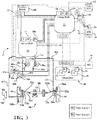
- a third embodiment of the present invention is shown in Figure 3 , with like numbers referring to like elements.
- first brake conduit 74a connected to and in fluid communication with the backup BCM 20 and the first brake unit 28a.
- second brake conduit 74b connected to and in fluid communication with the backup BCM 20 and the second brake unit 28b.
- the first fluid conduit 62a is connected to and in fluid communication with the first brake conduit 74a
- the second fluid conduit 62b is connected to and in fluid communication with the second brake conduit 74b.
- This embodiment also includes the uni-directional hydraulic motors 72a,72b, such that the motors 72a,72b and the steering system 50 function in the same manner as the embodiment shown in Figure 2 .
- the wheels 56a,56b are configured for making a right-hand turn
- the wheels 56a,56b are configured for making a left-hand turn
- the backup BCM 20 pumps fluid through the first brake conduit 74a, such that fluid is also pumped through the first fluid conduit 62a.
- both the first brake unit 28a is actuated, and the first uni-directional hydraulic motor 72a is also actuated such that the wheels 56a,56b are configured for making a right-hand turn in the same manner as described in the embodiment shown in Figure 2 . This simultaneously causes the vehicle to brake and decrease speed, as well as steer to the right.
- the second fluid conduit 62b also functions as a return conduit, as described in the previous embodiment.
- the backup BCM 20 pumps fluid through the second brake conduit 74b, such that fluid is also pumped through the second fluid conduit 62b.
- both the second brake unit 28b is actuated, and the second uni-directional hydraulic motor 72b is also actuated such that the wheels 56a,56b are configured for making a left-hand turn. This simultaneously causes the vehicle to brake and decrease speed, as well as steer to the left.
- the first fluid conduit 62b also functions as a return conduit, as described in the previous embodiment.
- the third embodiment of the present invention also includes a third mode of operation.
- BCM 20 pumps fluid through both fluid conduits 62a,62b and both brake conduits 74a,74b such that both of the brake units 28a,28b are actuated, and fluid is pumped to each uni-directional hydraulic motor 72a,72b.
- the motors 72a,72b work against each other such that the wheels 56a,56b remain in the position shown in Figure 3 , and the vehicle moves in a substantially straight direction while braking.
- the backup BCM 20 may be used to control the steering system 50 for an indefinite period of time, or a defined period of time. In one embodiment, the backup BCM 20 is used to control the steering system 50 for as long as desired, such that the vehicle may reach a specific destination. In another embodiment, the backup BCM 20 may be used to control the steering system 50 long enough to bring the vehicle to a controlled stop, such as the side of a road, or a parking lot, after the primary controls of the steering system 50 have failed.
Landscapes
- Engineering & Computer Science (AREA)
- Mechanical Engineering (AREA)
- Transportation (AREA)
- Combustion & Propulsion (AREA)
- Chemical & Material Sciences (AREA)
- General Engineering & Computer Science (AREA)
- Automation & Control Theory (AREA)
- Physics & Mathematics (AREA)
- Fluid Mechanics (AREA)
- Valves And Accessory Devices For Braking Systems (AREA)
- Steering Control In Accordance With Driving Conditions (AREA)
- Control Of Driving Devices And Active Controlling Of Vehicle (AREA)
- Power Steering Mechanism (AREA)
- Braking Systems And Boosters (AREA)
Claims (18)
- Vorrichtung, Folgendes umfassend:
ein Bremssystem, das dazu funktionsfähig ist, ein Lenksystem zu steuern, Folgendes umfassend:ein primäres Bremssteuerungsmodul, um den Fluiddruck im Bremssystem zu steuern;ein sekundäres Bremssteuerungsmodul, um den Fluiddruck im Bremssystem unabhängig vom primären Bremssteuerungsmodul zu steuern;mindestens eine Bremseinheit, die vom primären Bremssteuerungsmodul oder vom sekundären Bremssteuerungsmodul gesteuert wird, wobei die mindestens eine Bremseinheit dazu verwendet wird, ein Fahrzeug zu verlangsamen;mindestens einen Hydraulikmotor, der vom sekundären Bremssteuerungsmodul gesteuert wird;ein Lenksystem, das zum Lenken des Fahrzeugs verwendet wird, wobei der mindestens eine Hydraulikmotor Teil des Lenksystems ist;mindestens ein Rad, das Teil des Lenksystems ist;einen virtuellen Fahrer, der mit dem primären Bremssteuerungsmodul und dem sekundären Bremssteuerungsmodul elektrisch kommuniziert;einen ersten Betriebsmodus, wobei das mindestens eine Rad dazu ausgelegt ist, während des ersten Betriebsmodus rechts abzubiegen; undeinen zweiten Betriebsmodus, wobei das mindestens eine Rad dazu ausgelegt ist, während des zweiten Betriebsmodus links abzubiegen;wobei der virtuelle Fahrer Befehle an das sekundäre Bremssteuerungsmodul senden kann, sodass das sekundäre Bremssteuerungsmodul den mindestens einen Hydraulikmotor im ersten Betriebsmodus betreibt, um rechts abzubiegen, und das sekundäre Bremssteuerungsmodul den mindestens einen Hydraulikmotor im zweiten Betriebsmodus betreibt, um links abzubiegen. - Vorrichtung nach Anspruch 1, ferner Folgendes umfassend:eine erste Fluidleitung, die mit dem mindestens einen Hydraulikmotor verbunden ist und in Fluidverbindung steht; undeine zweite Fluidleitung, die mit dem mindestens einen Hydraulikmotor verbunden ist und in Fluidverbindung steht;wobei im ersten Betriebsmodus Fluid vom sekundären Bremssteuerungsmodul durch die erste Fluidleitung zu dem mindestens einen Hydraulikmotor gepumpt wird und Fluid von dem mindestens einen Hydraulikmotor durch die zweite Fluidleitung zum sekundären Bremssteuerungsmodul gepumpt wird und im zweiten Betriebsmodus Fluid vom sekundären Bremssteuerungsmodul durch die zweite Fluidleitung zu dem mindestens einen Hydraulikmotor gepumpt wird und Fluid von dem mindestens einen Hydraulikmotor durch die erste Fluidleitung zum sekundären Bremssteuerungsmodul gepumpt wird.
- Vorrichtung nach Anspruch 2, wobei der mindestens eine Hydraulikmotor ferner Folgendes umfasst:einen ersten Hydraulikmotor, der mit einer ersten Komponente des Lenksystems verbunden ist, wobei der erste Hydraulikmotor mit der ersten Fluidleitung verbunden ist und in Fluidverbindung steht; undeinen zweiten Hydraulikmotor, der mit einer zweiten Komponente des Lenksystems verbunden ist, wobei der zweite Hydraulikmotor mit der zweiten Fluidleitung verbunden ist und in Fluidverbindung steht;wobei im ersten Betriebsmodus Fluid vom sekundären Bremssteuerungsmodul durch die erste Fluidleitung zum ersten Hydraulikmotor gepumpt wird, um den ersten Hydraulikmotor zu betätigen, und Fluid vom zweiten Hydraulikmotor durch die zweite Fluidleitung zum sekundären Bremssteuerungsmodul gepumpt wird und im zweiten Betriebsmodus Fluid vom sekundären Bremssteuerungsmodul durch die zweite Fluidleitung zum zweiten Hydraulikmotor gepumpt wird, um den zweiten Hydraulikmotor zu betätigen, und Fluid vom ersten Hydraulikmotor durch die erste Fluidleitung zum sekundären Bremssteuerungsmodul gepumpt wird.
- Vorrichtung nach Anspruch 3, ferner Folgendes umfassend:dass die mindestens eine Bremseinheit ferner eine erste Bremseinheit umfasst;eine erste Bremsleitung, die mit der ersten Fluidleitung verbunden ist und in Fluidverbindung steht, wobei die erste Bremsleitung außerdem mit dem sekundären Bremssteuerungsmodul und der ersten Bremseinheit verbunden ist und in Fluidverbindung steht, sodass im ersten Betriebsmodus Fluid vom sekundären Bremssteuerungsmodul durch die erste Fluidleitung zum ersten Hydraulikmotor gepumpt wird, um den ersten Hydraulikmotor zu betätigen, und durch die erste Bremsleitung, um die erste Bremseinheit zu betätigen;wobei die mindestens eine Bremseinheit ferner eine zweite Bremseinheit umfasst; undeine zweite Bremsleitung, die mit der zweiten Fluidleitung verbunden ist und in Fluidverbindung steht, wobei die zweite Bremsleitung außerdem mit dem sekundären Bremssteuerungsmodul und der zweiten Bremseinheit verbunden ist und in Fluidverbindung steht, sodass im zweiten Betriebsmodus Fluid vom sekundären Bremssteuerungsmodul durch die zweite Fluidleitung zum zweiten Hydraulikmotor gepumpt wird, um den zweiten Hydraulikmotor zu betätigen, und durch die zweite Bremsleitung, um die zweite Bremseinheit zu betätigen;wobei der erste Hydraulikmotor und die erste Bremseinheit im ersten Betriebsmodus gleichzeitig betätigt werden und der zweite Hydraulikmotor und die zweite Bremseinheit im zweiten Betriebsmodus gleichzeitig betätigt werden.
- Vorrichtung nach Anspruch 4, ferner einen dritten Betriebsmodus umfassend, wobei im dritten Betriebsmodus Fluid vom sekundären Bremssteuerungsmodul durch die erste Fluidleitung zum ersten Hydraulikmotor gepumpt wird, um den ersten Hydraulikmotor zu betätigen, und durch die erste Bremsleitung, um die erste Bremseinheit zu betätigen, und Fluid außerdem vom sekundären Bremssteuerungsmodul durch die zweite Fluidleitung zum zweiten Hydraulikmotor gepumpt wird, um den zweiten Hydraulikmotor zu betätigen, und durch die zweite Bremsleitung, um die zweite Bremseinheit zu betätigen.
- Vorrichtung nach Anspruch 4, wobei der erste Hydraulikmotor, die erste Bremseinheit, der zweite Hydraulikmotor und die zweite Bremseinheit im dritten Betriebsmodus gleichzeitig betätigt werden, sodass das Fahrzeug verlangsamt wird und sich im Wesentlichen geradeaus bewegt.
- Bremssystem, das dazu funktionsfähig ist, ein Lenksystem zu steuern, Folgendes umfassend:ein primäres Bremssteuerungsmodul, um den Fluiddruck im Bremssystem zu steuern;ein sekundäres Bremssteuerungsmodul, um den Fluiddruck im Bremssystem unabhängig vom primären Bremssteuerungsmodul zu steuern;mehrere Bremseinheiten, die vom primären Bremssteuerungsmodul oder vom sekundären Bremssteuerungsmodul gesteuert werden, wobei die mehreren Bremseinheiten dazu verwendet werden, das Fahrzeug zu verlangsamen;mindestens einen Hydraulikmotor, wobei der Fluiddruck in dem mindestens einen Hydraulikmotor vom sekundären Bremssteuerungsmodul gesteuert wird;ein Lenksystem, das zum Lenken des Fahrzeugs verwendet wird, wobei der mindestens eine Hydraulikmotor mit einer Komponente des Lenksystems verbunden ist;mehrere Räder, die Teil des Lenksystems sind;eine erste Fluidleitung, die mit dem mindestens einen Hydraulikmotor und dem sekundären Bremssteuerungsmodul verbunden ist und in Fluidverbindung steht; undeine zweite Fluidleitung, die mit dem mindestens einen Hydraulikmotor und dem sekundären Bremssteuerungsmodul verbunden ist und in Fluidverbindung steht;einen virtuellen Fahrer, der mit dem primären Bremssteuerungsmodul und dem sekundären Bremssteuerungsmodul elektrisch kommuniziert;einen ersten Betriebsmodus, wobei im ersten Betriebsmodus Fluid vom sekundären Bremssteuerungsmodul durch die erste Fluidleitung zu dem mindestens einen Hydraulikmotor gepumpt wird und Fluid von dem mindestens einen Hydraulikmotor durch die zweite Fluidleitung zum sekundären Bremssteuerungsmodul gepumpt wird; undeinen zweiten Betriebsmodus, wobei im zweiten Betriebsmodus Fluid vom sekundären Bremssteuerungsmodul durch die zweite Fluidleitung zu dem mindestens einen Hydraulikmotor gepumpt wird und Fluid von dem mindestens einen Hydraulikmotor durch die erste Fluidleitung zum sekundären Bremssteuerungsmodul gepumpt wird;wobei die mehreren Räder dazu ausgelegt sind, rechts abzubiegen, wenn das sekundäre Bremssteuerungsmodul den mindestens einen Hydraulikmotor im ersten Betriebsmodus betreibt, und wobei die mehreren Räder dazu ausgelegt sind, links abzubiegen, wenn das sekundäre Bremssteuerungsmodul den mindestens einen Hydraulikmotor im zweiten Betriebsmodus betreibt.
- Bremssystem, das dazu funktionsfähig ist, ein Lenksystem nach Anspruch 7 zu steuern, wobei das sekundäre Bremssteuerungsmodul aktiv ist und den Fluiddruck im sekundären Bremssystem steuert, wenn im primären Bremssystem eine Fehlfunktion auftritt.
- Bremssystem, das dazu funktionsfähig ist, ein Lenksystem nach Anspruch 7 zu steuern, wobei der mindestens eine Hydraulikmotor ferner Folgendes umfasst:einen ersten Hydraulikmotor, der mit einer ersten Komponente des Lenksystems verbunden ist, wobei der erste Hydraulikmotor mit der ersten Fluidleitung verbunden ist und in Fluidverbindung steht; undeinen zweiten Hydraulikmotor, der mit einer zweiten Komponente des Lenksystems verbunden ist, wobei der zweite Hydraulikmotor mit der zweiten Fluidleitung verbunden ist und in Fluidverbindung steht;wobei im ersten Betriebsmodus Fluid vom sekundären Bremssteuerungsmodul durch die erste Fluidleitung zum ersten Hydraulikmotor gepumpt wird, um den ersten Hydraulikmotor zu betätigen, und Fluid vom zweiten Hydraulikmotor durch die zweite Fluidleitung zum sekundären Bremssteuerungsmodul gepumpt wird und im zweiten Betriebsmodus Fluid vom sekundären Bremssteuerungsmodul durch die zweite Fluidleitung zum zweiten Hydraulikmotor gepumpt wird, um den zweiten Hydraulikmotor zu betätigen, und Fluid vom ersten Hydraulikmotor durch die erste Fluidleitung zum sekundären Bremssteuerungsmodul gepumpt wird.
- Bremssystem, das dazu funktionsfähig ist, ein Lenksystem nach Anspruch 9 zu steuern, ferner Folgendes umfassend:eine erste Bremseinheit, wobei die erste Bremseinheit, eine der mehreren Bremseinheiten ist;eine erste Bremsleitung, die mit der ersten Fluidleitung verbunden ist und in Fluidverbindung steht, wobei die erste Bremsleitung außerdem mit dem sekundären Bremssteuerungsmodul und der ersten Bremseinheit verbunden ist und in Fluidverbindung steht, sodass im ersten Betriebsmodus Fluid vom sekundären Bremssteuerungsmodul durch die erste Fluidleitung zum ersten Hydraulikmotor gepumpt wird, um den ersten Hydraulikmotor zu betätigen, und durch die erste Bremsleitung, um die erste Bremseinheit zu betätigen;eine zweite Bremseinheit, wobei die zweite Bremseinheit, eine der mehreren Bremseinheiten ist; undeine zweite Bremsleitung, die mit der zweiten Fluidleitung verbunden ist und in Fluidverbindung steht, wobei die zweite Bremsleitung außerdem mit dem sekundären Bremssteuerungsmodul und der zweiten Bremseinheit verbunden ist und in Fluidverbindung steht, sodass im zweiten Betriebsmodus Fluid vom sekundären Bremssteuerungsmodul durch die zweite Fluidleitung zum zweiten Hydraulikmotor gepumpt wird, um den zweiten Hydraulikmotor zu betätigen, und durch die zweite Bremsleitung, um die zweite Bremseinheit zu betätigen;wobei der erste Hydraulikmotor und die erste Bremseinheit im ersten Betriebsmodus gleichzeitig betätigt werden und der zweite Hydraulikmotor und die zweite Bremseinheit im zweiten Betriebsmodus gleichzeitig betätigt werden.
- Bremssystem, das dazu funktionsfähig ist, ein Lenksystem nach Anspruch 10 zu steuern, ferner einen dritten Betriebsmodus umfassend, wobei im dritten Betriebsmodus Fluid vom sekundären Bremssteuerungsmodul durch die erste Fluidleitung zum ersten Hydraulikmotor gepumpt wird, um den ersten Hydraulikmotor zu betätigen, und durch die erste Bremsleitung, um die erste Bremseinheit zu betätigen, und Fluid außerdem vom sekundären Bremssteuerungsmodul durch die zweite Fluidleitung zum zweiten Hydraulikmotor gepumpt wird, um den zweiten Hydraulikmotor zu betätigen, und durch die zweite Bremsleitung, um die zweite Bremseinheit zu betätigen.
- Bremssystem, das dazu funktionsfähig ist, ein Lenksystem nach Anspruch 11 zu steuern, wobei der erste Hydraulikmotor, die erste Bremseinheit, der zweite Hydraulikmotor und die zweite Bremseinheit im dritten Betriebsmodus gleichzeitig betätigt werden, sodass das Fahrzeug verlangsamt wird und sich im Wesentlichen geradeaus bewegt.
- Bremssystem, das dazu funktionsfähig ist, ein Lenksystem nach Anspruch 10 zu steuern, wobei das sekundäre Bremssteuerungsmodul die erste Bremseinheit und die zweite Bremseinheit auf Grundlage von Eingaben des virtuellen Fahrers steuert, wenn das sekundäre Bremssteuerungsmodul aktiv ist.
- Verfahren zum Steuern eines Lenksystems mit einem redundanten Bremssystem eines Fahrzeugs, die folgenden Schritte umfassend:Vorsehen eines primären Bremssteuerungsmoduls;Vorsehen eines sekundären Bremssteuerungsmoduls;Vorsehen mehrerer Bremseinheiten, die vom primären Bremssteuerungsmodul oder vom sekundären Bremssteuerungsmodul gesteuert werden;Vorsehen eines Lenksystems;Vorsehen mehrerer Räder, die Teil des Lenksystems sind;Vorsehen mindestens eines Hydraulikmotors, der durch das sekundäre Bremssteuerungsmodul gesteuert wird, wobei der mindestens eine Hydraulikmotor mit mindestens einer Komponente des Lenksystems verbunden ist;Vorsehen eines virtuellen Fahrers, der mit dem primären Bremssteuerungsmodul und dem sekundären Bremssteuerungsmodul elektrisch kommuniziert;Vorsehen eines ersten Betriebsmodus; undVorsehen eines zweiten Betriebsmodus;Senden von Befehlen zum sekundären Bremssteuerungsmodul vom virtuellen Fahrer, um den mindestens einen Hydraulikmotor im ersten Betriebsmodus oder im zweiten Betriebsmodus zu betreiben;Auslegen der mehreren Räder, um im ersten Betriebsmodus rechts abzubiegen;Auslegen der mehreren Räder, um im zweiten Betriebsmodus links abzubiegen.
- Verfahren nach Anspruch 14, ferner die folgenden Schritte umfassend:Vorsehen einer ersten Fluidleitung, die mit dem mindestens einen Hydraulikmotor verbunden ist und in Fluidverbindung steht; undVorsehen einer zweiten Fluidleitung, die mit dem mindestens einen Hydraulikmotor verbunden ist und in Fluidverbindung steht;Pumpen von Fluid vom sekundären Bremssteuerungsmodul durch die erste Fluidleitung zum mindestens einen Hydraulikmotor im ersten Betriebsmodus;Pumpen von Fluid vom mindestens einen Hydraulikmotor durch die zweite Fluidleitung zum sekundären Bremssteuerungsmodul im ersten Betriebsmodus;Pumpen von Fluid vom sekundären Bremssteuerungsmodul durch die zweite Fluidleitung zum mindestens einen Hydraulikmotor im ersten Betriebsmodus;Pumpen von Fluid vom mindestens einen Hydraulikmotor durch die erste Fluidleitung zum sekundären Bremssteuerungsmodul im zweiten Betriebsmodus.
- Verfahren nach Anspruch 15, ferner die folgenden Schritte umfassend:Vorsehen des mindestens einen Hydraulikmotors, um einen ersten Hydraulikmotor zu umfassen, der mit einer ersten Komponente des Lenksystems verbunden ist;Vorsehen des mindestens einen Hydraulikmotors, um einen zweiten Hydraulikmotor zu umfassen, der mit einer zweiten Komponente des Lenksystems verbunden ist;Pumpen von Fluid vom sekundären Bremssteuerungsmodul durch die erste Fluidleitung zum ersten Hydraulikmotor, um den ersten Hydraulikmotor zu betätigen, sodass im ersten Betriebsmodus Fluid vom zweiten Hydraulikmotor durch die zweite Fluidleitung und zum sekundären Bremssteuerungsmodul gepumpt wird;Pumpen von Fluid vom sekundären Bremssteuerungsmodul durch die zweite Fluidleitung zum zweiten Hydraulikmotor, um den zweiten Hydraulikmotor zu betätigen, sodass im zweiten Betriebsmodus Fluid vom ersten Hydraulikmotor durch die erste Fluidleitung und zum sekundären Bremssteuerungsmodul gepumpt wird.
- Verfahren nach Anspruch 16, ferner die folgenden Schritte umfassend:Vorsehen der mehreren Bremseinheiten, um eine erste Bremseinheit zu umfassen;Vorsehen der mehreren Bremseinheiten, um eine zweite Bremseinheit zu umfassen;Vorsehen einer ersten Bremsleitung, die mit dem sekundären Bremssteuerungsmodul und der ersten Bremseinheit verbunden ist und in Fluidverbindung steht, wobei die erste Fluidleitung außerdem mit der ersten Bremsleitung verbunden ist und in Fluidverbindung steht;Vorsehen einer zweiten Bremsleitung, die mit dem sekundären Bremssteuerungsmodul und der zweiten Bremseinheit verbunden ist und in Fluidverbindung steht, wobei die zweite Fluidleitung außerdem mit der zweiten Bremsleitung verbunden ist und in Fluidverbindung steht;Pumpen von Fluid vom sekundären Bremssteuerungsmodul durch die erste Fluidleitung zum ersten Hydraulikmotor und zur ersten Bremsleitung, sodass der erste Hydraulikmotor und die erste Bremseinheit im ersten Betriebsmodus gleichzeitig betätigt werden;Pumpen von Fluid vom sekundären Bremssteuerungsmodul durch die zweite Fluidleitung zum zweiten Hydraulikmotor und zur zweiten Bremsleitung, sodass der zweite Hydraulikmotor und die zweite Bremseinheit im zweiten Betriebsmodus gleichzeitig betätigt werden.
- Verfahren nach Anspruch 17, ferner die folgenden Schritte umfassend:Vorsehen eines dritten Betriebsmodus;gleichzeitiges Betätigen des ersten Hydraulikmotors, des zweiten Hydraulikmotors, der ersten Bremseinheit und der zweiten Bremseinheit im dritten Betriebsmodus, sodass sich das Fahrzeug im Wesentlichen geradeaus verlangsamt.
Applications Claiming Priority (2)
| Application Number | Priority Date | Filing Date | Title |
|---|---|---|---|
| US15/287,424 US10137931B2 (en) | 2016-10-06 | 2016-10-06 | Redundant steering controls for automated driving |
| PCT/US2017/055137 WO2018067699A1 (en) | 2016-10-06 | 2017-10-04 | Redundant steering controls for automated driving |
Publications (2)
| Publication Number | Publication Date |
|---|---|
| EP3548362A1 EP3548362A1 (de) | 2019-10-09 |
| EP3548362B1 true EP3548362B1 (de) | 2021-01-20 |
Family
ID=60117823
Family Applications (1)
| Application Number | Title | Priority Date | Filing Date |
|---|---|---|---|
| EP17784803.3A Active EP3548362B1 (de) | 2016-10-06 | 2017-10-04 | Redundante lenkkontrollen für automatisiertes fahren |
Country Status (5)
| Country | Link |
|---|---|
| US (1) | US10137931B2 (de) |
| EP (1) | EP3548362B1 (de) |
| JP (1) | JP6914327B2 (de) |
| CN (1) | CN109789892B (de) |
| WO (1) | WO2018067699A1 (de) |
Families Citing this family (15)
| Publication number | Priority date | Publication date | Assignee | Title |
|---|---|---|---|---|
| US10618506B2 (en) | 2016-11-28 | 2020-04-14 | Allison Transmission, Inc. | Utilization of brakes and transmission system to affect steering of a vehicle and method thereof |
| US10752282B2 (en) * | 2017-10-04 | 2020-08-25 | Steering Solutions Ip Holding Corporation | Triple redundancy failsafe for steering systems |
| EP3626555B1 (de) * | 2018-09-18 | 2022-07-20 | KNORR-BREMSE Systeme für Nutzfahrzeuge GmbH | Steuerungsarchitektur für elektrifiziertes bremsen und elektrifiziertes lenken eines fahrzeugs |
| JP7061055B2 (ja) * | 2018-11-06 | 2022-04-27 | 日立Astemo株式会社 | ステアリング装置 |
| CN109917779A (zh) * | 2019-03-26 | 2019-06-21 | 中国第一汽车股份有限公司 | 面向l3自动驾驶的冗余控制系统 |
| CN113365878B (zh) * | 2019-09-03 | 2025-06-06 | 北京航迹科技有限公司 | 自动驾驶系统的冗余结构 |
| US11427175B2 (en) | 2019-12-16 | 2022-08-30 | Waymo Llc | Vehicle braking systems and methods |
| CN112319653B (zh) * | 2020-09-30 | 2021-10-12 | 中国煤炭科工集团太原研究院有限公司 | 一种煤矿井下无轨辅助运输机器人 |
| EP4063238B1 (de) * | 2021-03-22 | 2026-02-18 | Volvo Truck Corporation | Lenkbare radachsenanordnung und verfahren zur steuerung einer lenkbaren radachsenanordnung |
| US20230130534A1 (en) * | 2021-10-26 | 2023-04-27 | Ford Global Technologies, Llc | Methods and apparatus for vehicle turning in confined spaces |
| CN114274941B (zh) * | 2022-01-06 | 2024-06-07 | 唐义诚 | 一种智能转向触发相应速度变化的控制系统 |
| WO2023146354A1 (ko) * | 2022-01-27 | 2023-08-03 | 에이치엘만도 주식회사 | 브레이크 장치 및 그 제어 방법 |
| CN114559920A (zh) * | 2022-03-25 | 2022-05-31 | 苏州海之博电子科技有限公司 | Ipb与ehps或eps安全冗余系统 |
| CN114715171A (zh) * | 2022-03-31 | 2022-07-08 | 重庆长安汽车股份有限公司 | L4级及以上自动驾驶的自适应整车电子电器架构及车辆 |
| CN116985901A (zh) * | 2023-05-29 | 2023-11-03 | 北京踏歌智行科技有限公司 | 一种无人驾驶矿用自卸车冗余转向控制系统和方法 |
Family Cites Families (10)
| Publication number | Priority date | Publication date | Assignee | Title |
|---|---|---|---|---|
| US2347241A (en) * | 1942-06-27 | 1944-04-25 | Wagner Electric Corp | Brake control system |
| DE1655926A1 (de) * | 1967-04-05 | 1971-07-22 | Zahnradfabrik Friedrichshafen | Elektrohydraulische Stellvorrichtung fuer die Einrichtung zur UEbersteuerung des Hauptfahrstandes von Kraftfahrzeugen |
| SE447566B (sv) * | 1986-01-24 | 1986-11-24 | Hegglund & Soner Ab | Forfarande och anordning for styrning av fordon |
| US20020005302A1 (en) * | 1999-09-16 | 2002-01-17 | Shigemi Hidaka | Working vehicle |
| DE19946073A1 (de) * | 1999-09-25 | 2001-05-10 | Volkswagen Ag | System zur Steuerung von Fahrzeugkomponenten nach dem "Drive By Wire"-Prinzip |
| JP2001294164A (ja) * | 2000-04-11 | 2001-10-23 | Koyo Seiko Co Ltd | 車両用操舵装置 |
| JP3872992B2 (ja) * | 2002-03-08 | 2007-01-24 | カヤバ工業株式会社 | 自動操舵システム |
| CN102815335B (zh) | 2012-09-06 | 2015-06-10 | 三一矿机有限公司 | 一种转向制动集成控制系统及矿用自卸车 |
| DE102014220440A1 (de) | 2014-01-15 | 2015-07-16 | Continental Teves Ag & Co. Ohg | Bremsensteuervorrichtung sowie Bremsanlage für Fahrzeuge |
| SE539681C2 (sv) | 2014-11-28 | 2017-10-31 | Scania Cv Ab | Förfarande och system för tillhandahållande av servostyrningsassistans vid styrservobortfall |
-
2016
- 2016-10-06 US US15/287,424 patent/US10137931B2/en not_active Expired - Fee Related
-
2017
- 2017-10-04 JP JP2019518518A patent/JP6914327B2/ja active Active
- 2017-10-04 EP EP17784803.3A patent/EP3548362B1/de active Active
- 2017-10-04 WO PCT/US2017/055137 patent/WO2018067699A1/en not_active Ceased
- 2017-10-04 CN CN201780061903.2A patent/CN109789892B/zh active Active
Non-Patent Citations (1)
| Title |
|---|
| None * |
Also Published As
| Publication number | Publication date |
|---|---|
| WO2018067699A1 (en) | 2018-04-12 |
| EP3548362A1 (de) | 2019-10-09 |
| US10137931B2 (en) | 2018-11-27 |
| JP2020500118A (ja) | 2020-01-09 |
| CN109789892B (zh) | 2026-03-24 |
| US20180099694A1 (en) | 2018-04-12 |
| CN109789892A (zh) | 2019-05-21 |
| JP6914327B2 (ja) | 2021-08-04 |
Similar Documents
| Publication | Publication Date | Title |
|---|---|---|
| EP3548362B1 (de) | Redundante lenkkontrollen für automatisiertes fahren | |
| EP3448730B1 (de) | Fahrzeug, bremssystem und verfahren zum fahrerunabhängigen bremsen eines fahrzeugs | |
| CN105829177B (zh) | 机动车 | |
| JP5254334B2 (ja) | 車両用ブレーキ装置および車両用ブレーキ装置の作動方法 | |
| CN107709139A (zh) | 具有前桥转向系统和后桥转向系统的自动驾驶的机动车 | |
| KR102050471B1 (ko) | 브레이크 제어 장치 | |
| US10683000B2 (en) | Hydraulic safety system, brake system, and operating method | |
| US9296370B2 (en) | Hydraulic and electronic braking system for autonomous braking | |
| KR101724902B1 (ko) | 차량의 통합형 전, 후륜 파워 조향 시스템 및 그 제어 방법 | |
| CN113329924A (zh) | 制动系统 | |
| JP7217655B2 (ja) | 作業車両 | |
| US11548488B2 (en) | Control devices for motorized pressure build-up devices and method for transmitting at least one piece of information between two motorized pressure build-up devices | |
| CN111874099A (zh) | 车辆转向的控制方法和车辆的线控转向装置 | |
| SE530628C3 (sv) | Ledstyrsystem | |
| CN115246438A (zh) | 用于操纵车辆的方法 | |
| US12447980B2 (en) | System unit including a first actuator system and a second actuator system | |
| CN114981147B (zh) | 转向系统 | |
| US12351250B2 (en) | Auxiliary steering device for a hydrostatic vehicle steering system | |
| US12472915B2 (en) | Controlled deceleration for parking of a vehicle | |
| JP2007245821A (ja) | 車両用操舵装置 | |
| EP4663514A1 (de) | Hydraulische lenkeinrichtung zum lenken eines fahrzeugs mit einer lenkmechanik | |
| KR20130044734A (ko) | 차량자세제어를 위한 페일 세이프 제어 방법 및 장치 | |
| CN115489591A (zh) | 用于机动车的转向齿轮设备 | |
| JP2008132826A (ja) | 車両用操舵装置 |
Legal Events
| Date | Code | Title | Description |
|---|---|---|---|
| STAA | Information on the status of an ep patent application or granted ep patent |
Free format text: STATUS: UNKNOWN |
|
| STAA | Information on the status of an ep patent application or granted ep patent |
Free format text: STATUS: THE INTERNATIONAL PUBLICATION HAS BEEN MADE |
|
| PUAI | Public reference made under article 153(3) epc to a published international application that has entered the european phase |
Free format text: ORIGINAL CODE: 0009012 |
|
| STAA | Information on the status of an ep patent application or granted ep patent |
Free format text: STATUS: REQUEST FOR EXAMINATION WAS MADE |
|
| 17P | Request for examination filed |
Effective date: 20190506 |
|
| AK | Designated contracting states |
Kind code of ref document: A1 Designated state(s): AL AT BE BG CH CY CZ DE DK EE ES FI FR GB GR HR HU IE IS IT LI LT LU LV MC MK MT NL NO PL PT RO RS SE SI SK SM TR |
|
| AX | Request for extension of the european patent |
Extension state: BA ME |
|
| DAV | Request for validation of the european patent (deleted) | ||
| DAX | Request for extension of the european patent (deleted) | ||
| RIC1 | Information provided on ipc code assigned before grant |
Ipc: F16D 61/00 20060101ALI20200708BHEP Ipc: B60T 1/10 20060101ALI20200708BHEP Ipc: B60T 13/04 20060101ALI20200708BHEP Ipc: B60T 11/10 20060101ALI20200708BHEP Ipc: B62D 5/07 20060101AFI20200708BHEP Ipc: B62D 5/04 20060101ALI20200708BHEP Ipc: B62D 9/00 20060101ALI20200708BHEP Ipc: B60T 13/68 20060101ALI20200708BHEP |
|
| GRAP | Despatch of communication of intention to grant a patent |
Free format text: ORIGINAL CODE: EPIDOSNIGR1 |
|
| STAA | Information on the status of an ep patent application or granted ep patent |
Free format text: STATUS: GRANT OF PATENT IS INTENDED |
|
| INTG | Intention to grant announced |
Effective date: 20200929 |
|
| GRAS | Grant fee paid |
Free format text: ORIGINAL CODE: EPIDOSNIGR3 |
|
| GRAA | (expected) grant |
Free format text: ORIGINAL CODE: 0009210 |
|
| STAA | Information on the status of an ep patent application or granted ep patent |
Free format text: STATUS: THE PATENT HAS BEEN GRANTED |
|
| RAP1 | Party data changed (applicant data changed or rights of an application transferred) |
Owner name: CONTINENTAL AUTOMOTIVE SYSTEMS, INC. |
|
| AK | Designated contracting states |
Kind code of ref document: B1 Designated state(s): AL AT BE BG CH CY CZ DE DK EE ES FI FR GB GR HR HU IE IS IT LI LT LU LV MC MK MT NL NO PL PT RO RS SE SI SK SM TR |
|
| REG | Reference to a national code |
Ref country code: GB Ref legal event code: FG4D |
|
| REG | Reference to a national code |
Ref country code: CH Ref legal event code: EP |
|
| REG | Reference to a national code |
Ref country code: DE Ref legal event code: R096 Ref document number: 602017031731 Country of ref document: DE |
|
| REG | Reference to a national code |
Ref country code: AT Ref legal event code: REF Ref document number: 1356149 Country of ref document: AT Kind code of ref document: T Effective date: 20210215 |
|
| REG | Reference to a national code |
Ref country code: IE Ref legal event code: FG4D |
|
| REG | Reference to a national code |
Ref country code: SE Ref legal event code: TRGR |
|
| REG | Reference to a national code |
Ref country code: NL Ref legal event code: MP Effective date: 20210120 |
|
| REG | Reference to a national code |
Ref country code: LT Ref legal event code: MG9D |
|
| REG | Reference to a national code |
Ref country code: AT Ref legal event code: MK05 Ref document number: 1356149 Country of ref document: AT Kind code of ref document: T Effective date: 20210120 |
|
| PG25 | Lapsed in a contracting state [announced via postgrant information from national office to epo] |
Ref country code: LT Free format text: LAPSE BECAUSE OF FAILURE TO SUBMIT A TRANSLATION OF THE DESCRIPTION OR TO PAY THE FEE WITHIN THE PRESCRIBED TIME-LIMIT Effective date: 20210120 Ref country code: BG Free format text: LAPSE BECAUSE OF FAILURE TO SUBMIT A TRANSLATION OF THE DESCRIPTION OR TO PAY THE FEE WITHIN THE PRESCRIBED TIME-LIMIT Effective date: 20210420 Ref country code: FI Free format text: LAPSE BECAUSE OF FAILURE TO SUBMIT A TRANSLATION OF THE DESCRIPTION OR TO PAY THE FEE WITHIN THE PRESCRIBED TIME-LIMIT Effective date: 20210120 Ref country code: GR Free format text: LAPSE BECAUSE OF FAILURE TO SUBMIT A TRANSLATION OF THE DESCRIPTION OR TO PAY THE FEE WITHIN THE PRESCRIBED TIME-LIMIT Effective date: 20210421 Ref country code: HR Free format text: LAPSE BECAUSE OF FAILURE TO SUBMIT A TRANSLATION OF THE DESCRIPTION OR TO PAY THE FEE WITHIN THE PRESCRIBED TIME-LIMIT Effective date: 20210120 Ref country code: PT Free format text: LAPSE BECAUSE OF FAILURE TO SUBMIT A TRANSLATION OF THE DESCRIPTION OR TO PAY THE FEE WITHIN THE PRESCRIBED TIME-LIMIT Effective date: 20210520 Ref country code: NO Free format text: LAPSE BECAUSE OF FAILURE TO SUBMIT A TRANSLATION OF THE DESCRIPTION OR TO PAY THE FEE WITHIN THE PRESCRIBED TIME-LIMIT Effective date: 20210420 |
|
| PG25 | Lapsed in a contracting state [announced via postgrant information from national office to epo] |
Ref country code: LV Free format text: LAPSE BECAUSE OF FAILURE TO SUBMIT A TRANSLATION OF THE DESCRIPTION OR TO PAY THE FEE WITHIN THE PRESCRIBED TIME-LIMIT Effective date: 20210120 Ref country code: PL Free format text: LAPSE BECAUSE OF FAILURE TO SUBMIT A TRANSLATION OF THE DESCRIPTION OR TO PAY THE FEE WITHIN THE PRESCRIBED TIME-LIMIT Effective date: 20210120 Ref country code: RS Free format text: LAPSE BECAUSE OF FAILURE TO SUBMIT A TRANSLATION OF THE DESCRIPTION OR TO PAY THE FEE WITHIN THE PRESCRIBED TIME-LIMIT Effective date: 20210120 Ref country code: AT Free format text: LAPSE BECAUSE OF FAILURE TO SUBMIT A TRANSLATION OF THE DESCRIPTION OR TO PAY THE FEE WITHIN THE PRESCRIBED TIME-LIMIT Effective date: 20210120 |
|
| PG25 | Lapsed in a contracting state [announced via postgrant information from national office to epo] |
Ref country code: IS Free format text: LAPSE BECAUSE OF FAILURE TO SUBMIT A TRANSLATION OF THE DESCRIPTION OR TO PAY THE FEE WITHIN THE PRESCRIBED TIME-LIMIT Effective date: 20210520 |
|
| REG | Reference to a national code |
Ref country code: DE Ref legal event code: R097 Ref document number: 602017031731 Country of ref document: DE |
|
| PG25 | Lapsed in a contracting state [announced via postgrant information from national office to epo] |
Ref country code: CZ Free format text: LAPSE BECAUSE OF FAILURE TO SUBMIT A TRANSLATION OF THE DESCRIPTION OR TO PAY THE FEE WITHIN THE PRESCRIBED TIME-LIMIT Effective date: 20210120 Ref country code: EE Free format text: LAPSE BECAUSE OF FAILURE TO SUBMIT A TRANSLATION OF THE DESCRIPTION OR TO PAY THE FEE WITHIN THE PRESCRIBED TIME-LIMIT Effective date: 20210120 Ref country code: SM Free format text: LAPSE BECAUSE OF FAILURE TO SUBMIT A TRANSLATION OF THE DESCRIPTION OR TO PAY THE FEE WITHIN THE PRESCRIBED TIME-LIMIT Effective date: 20210120 |
|
| PLBE | No opposition filed within time limit |
Free format text: ORIGINAL CODE: 0009261 |
|
| STAA | Information on the status of an ep patent application or granted ep patent |
Free format text: STATUS: NO OPPOSITION FILED WITHIN TIME LIMIT |
|
| PG25 | Lapsed in a contracting state [announced via postgrant information from national office to epo] |
Ref country code: RO Free format text: LAPSE BECAUSE OF FAILURE TO SUBMIT A TRANSLATION OF THE DESCRIPTION OR TO PAY THE FEE WITHIN THE PRESCRIBED TIME-LIMIT Effective date: 20210120 Ref country code: DK Free format text: LAPSE BECAUSE OF FAILURE TO SUBMIT A TRANSLATION OF THE DESCRIPTION OR TO PAY THE FEE WITHIN THE PRESCRIBED TIME-LIMIT Effective date: 20210120 Ref country code: SK Free format text: LAPSE BECAUSE OF FAILURE TO SUBMIT A TRANSLATION OF THE DESCRIPTION OR TO PAY THE FEE WITHIN THE PRESCRIBED TIME-LIMIT Effective date: 20210120 |
|
| 26N | No opposition filed |
Effective date: 20211021 |
|
| PG25 | Lapsed in a contracting state [announced via postgrant information from national office to epo] |
Ref country code: AL Free format text: LAPSE BECAUSE OF FAILURE TO SUBMIT A TRANSLATION OF THE DESCRIPTION OR TO PAY THE FEE WITHIN THE PRESCRIBED TIME-LIMIT Effective date: 20210120 Ref country code: ES Free format text: LAPSE BECAUSE OF FAILURE TO SUBMIT A TRANSLATION OF THE DESCRIPTION OR TO PAY THE FEE WITHIN THE PRESCRIBED TIME-LIMIT Effective date: 20210120 |
|
| PG25 | Lapsed in a contracting state [announced via postgrant information from national office to epo] |
Ref country code: SI Free format text: LAPSE BECAUSE OF FAILURE TO SUBMIT A TRANSLATION OF THE DESCRIPTION OR TO PAY THE FEE WITHIN THE PRESCRIBED TIME-LIMIT Effective date: 20210120 |
|
| PG25 | Lapsed in a contracting state [announced via postgrant information from national office to epo] |
Ref country code: IS Free format text: LAPSE BECAUSE OF FAILURE TO SUBMIT A TRANSLATION OF THE DESCRIPTION OR TO PAY THE FEE WITHIN THE PRESCRIBED TIME-LIMIT Effective date: 20210520 |
|
| REG | Reference to a national code |
Ref country code: CH Ref legal event code: PL |
|
| REG | Reference to a national code |
Ref country code: BE Ref legal event code: MM Effective date: 20211031 |
|
| GBPC | Gb: european patent ceased through non-payment of renewal fee |
Effective date: 20211004 |
|
| PG25 | Lapsed in a contracting state [announced via postgrant information from national office to epo] |
Ref country code: MC Free format text: LAPSE BECAUSE OF FAILURE TO SUBMIT A TRANSLATION OF THE DESCRIPTION OR TO PAY THE FEE WITHIN THE PRESCRIBED TIME-LIMIT Effective date: 20210120 |
|
| PG25 | Lapsed in a contracting state [announced via postgrant information from national office to epo] |
Ref country code: LU Free format text: LAPSE BECAUSE OF NON-PAYMENT OF DUE FEES Effective date: 20211004 Ref country code: GB Free format text: LAPSE BECAUSE OF NON-PAYMENT OF DUE FEES Effective date: 20211004 Ref country code: BE Free format text: LAPSE BECAUSE OF NON-PAYMENT OF DUE FEES Effective date: 20211031 |
|
| PG25 | Lapsed in a contracting state [announced via postgrant information from national office to epo] |
Ref country code: LI Free format text: LAPSE BECAUSE OF NON-PAYMENT OF DUE FEES Effective date: 20211031 Ref country code: CH Free format text: LAPSE BECAUSE OF NON-PAYMENT OF DUE FEES Effective date: 20211031 |
|
| PG25 | Lapsed in a contracting state [announced via postgrant information from national office to epo] |
Ref country code: IE Free format text: LAPSE BECAUSE OF NON-PAYMENT OF DUE FEES Effective date: 20211004 |
|
| PG25 | Lapsed in a contracting state [announced via postgrant information from national office to epo] |
Ref country code: NL Free format text: LAPSE BECAUSE OF NON-PAYMENT OF DUE FEES Effective date: 20210120 Ref country code: CY Free format text: LAPSE BECAUSE OF FAILURE TO SUBMIT A TRANSLATION OF THE DESCRIPTION OR TO PAY THE FEE WITHIN THE PRESCRIBED TIME-LIMIT Effective date: 20210120 |
|
| PG25 | Lapsed in a contracting state [announced via postgrant information from national office to epo] |
Ref country code: HU Free format text: LAPSE BECAUSE OF FAILURE TO SUBMIT A TRANSLATION OF THE DESCRIPTION OR TO PAY THE FEE WITHIN THE PRESCRIBED TIME-LIMIT; INVALID AB INITIO Effective date: 20171004 |
|
| P01 | Opt-out of the competence of the unified patent court (upc) registered |
Effective date: 20230623 |
|
| PG25 | Lapsed in a contracting state [announced via postgrant information from national office to epo] |
Ref country code: MK Free format text: LAPSE BECAUSE OF FAILURE TO SUBMIT A TRANSLATION OF THE DESCRIPTION OR TO PAY THE FEE WITHIN THE PRESCRIBED TIME-LIMIT Effective date: 20210120 |
|
| PG25 | Lapsed in a contracting state [announced via postgrant information from national office to epo] |
Ref country code: MT Free format text: LAPSE BECAUSE OF FAILURE TO SUBMIT A TRANSLATION OF THE DESCRIPTION OR TO PAY THE FEE WITHIN THE PRESCRIBED TIME-LIMIT Effective date: 20210120 |
|
| PG25 | Lapsed in a contracting state [announced via postgrant information from national office to epo] |
Ref country code: TR Free format text: LAPSE BECAUSE OF FAILURE TO SUBMIT A TRANSLATION OF THE DESCRIPTION OR TO PAY THE FEE WITHIN THE PRESCRIBED TIME-LIMIT Effective date: 20210120 |
|
| PGFP | Annual fee paid to national office [announced via postgrant information from national office to epo] |
Ref country code: DE Payment date: 20251031 Year of fee payment: 9 |
|
| PGFP | Annual fee paid to national office [announced via postgrant information from national office to epo] |
Ref country code: IT Payment date: 20251024 Year of fee payment: 9 |
|
| PGFP | Annual fee paid to national office [announced via postgrant information from national office to epo] |
Ref country code: FR Payment date: 20251027 Year of fee payment: 9 |
|
| PGFP | Annual fee paid to national office [announced via postgrant information from national office to epo] |
Ref country code: SE Payment date: 20251024 Year of fee payment: 9 |