EP3548367B1 - Véhicule à mobilité à chenille en forme de glissière - Google Patents
Véhicule à mobilité à chenille en forme de glissière Download PDFInfo
- Publication number
- EP3548367B1 EP3548367B1 EP17872897.8A EP17872897A EP3548367B1 EP 3548367 B1 EP3548367 B1 EP 3548367B1 EP 17872897 A EP17872897 A EP 17872897A EP 3548367 B1 EP3548367 B1 EP 3548367B1
- Authority
- EP
- European Patent Office
- Prior art keywords
- track
- curvature
- vehicle
- tracks
- rollers
- Prior art date
- Legal status (The legal status is an assumption and is not a legal conclusion. Google has not performed a legal analysis and makes no representation as to the accuracy of the status listed.)
- Active
Links
Images


Classifications
-
- B—PERFORMING OPERATIONS; TRANSPORTING
- B62—LAND VEHICLES FOR TRAVELLING OTHERWISE THAN ON RAILS
- B62D—MOTOR VEHICLES; TRAILERS
- B62D55/00—Endless track vehicles
- B62D55/08—Endless track units; Parts thereof
- B62D55/18—Tracks
- B62D55/20—Tracks of articulated type, e.g. chains
- B62D55/22—Arrangements for preventing or modifying back-flexing
-
- B—PERFORMING OPERATIONS; TRANSPORTING
- B60—VEHICLES IN GENERAL
- B60K—ARRANGEMENT OR MOUNTING OF PROPULSION UNITS OR OF TRANSMISSIONS IN VEHICLES; ARRANGEMENT OR MOUNTING OF PLURAL DIVERSE PRIME-MOVERS IN VEHICLES; AUXILIARY DRIVES FOR VEHICLES; INSTRUMENTATION OR DASHBOARDS FOR VEHICLES; ARRANGEMENTS IN CONNECTION WITH COOLING, AIR INTAKE, GAS EXHAUST OR FUEL SUPPLY OF PROPULSION UNITS IN VEHICLES
- B60K26/00—Arrangement or mounting of propulsion-unit control devices in vehicles
- B60K26/02—Arrangement or mounting of propulsion-unit control devices in vehicles of initiating means or elements
-
- B—PERFORMING OPERATIONS; TRANSPORTING
- B60—VEHICLES IN GENERAL
- B60Q—ARRANGEMENT OF SIGNALLING OR LIGHTING DEVICES, THE MOUNTING OR SUPPORTING THEREOF OR CIRCUITS THEREFOR, FOR VEHICLES IN GENERAL
- B60Q1/00—Arrangement of optical signalling or lighting devices, the mounting or supporting thereof or circuits therefor
- B60Q1/02—Arrangement of optical signalling or lighting devices, the mounting or supporting thereof or circuits therefor the devices being primarily intended to illuminate the way ahead or to illuminate other areas of way or environments
-
- B—PERFORMING OPERATIONS; TRANSPORTING
- B62—LAND VEHICLES FOR TRAVELLING OTHERWISE THAN ON RAILS
- B62D—MOTOR VEHICLES; TRAILERS
- B62D51/00—Motor vehicles characterised by the driver not being seated
- B62D51/02—Motor vehicles characterised by the driver not being seated the driver standing in the vehicle
-
- B—PERFORMING OPERATIONS; TRANSPORTING
- B62—LAND VEHICLES FOR TRAVELLING OTHERWISE THAN ON RAILS
- B62D—MOTOR VEHICLES; TRAILERS
- B62D55/00—Endless track vehicles
- B62D55/06—Endless track vehicles with tracks without ground wheels
- B62D55/065—Multi-track vehicles, i.e. more than two tracks
-
- B—PERFORMING OPERATIONS; TRANSPORTING
- B62—LAND VEHICLES FOR TRAVELLING OTHERWISE THAN ON RAILS
- B62D—MOTOR VEHICLES; TRAILERS
- B62D55/00—Endless track vehicles
- B62D55/06—Endless track vehicles with tracks without ground wheels
- B62D55/075—Tracked vehicles for ascending or descending stairs, steep slopes or vertical surfaces
-
- B—PERFORMING OPERATIONS; TRANSPORTING
- B62—LAND VEHICLES FOR TRAVELLING OTHERWISE THAN ON RAILS
- B62D—MOTOR VEHICLES; TRAILERS
- B62D55/00—Endless track vehicles
- B62D55/08—Endless track units; Parts thereof
- B62D55/18—Tracks
- B62D55/20—Tracks of articulated type, e.g. chains
- B62D55/205—Connections between track links
Definitions
- the present invention relates to a mobility vehicle similar to bicycle, scooter, motorcycle, segway, wheelchair, scooter for elderly or recent class of "rideable vehicles". It could be also a multi-person vehicle similar to a car with high off-road drivability, cross-country agility, traction in deep snow or sand.
- Mobility vehicles are mostly based on wheels for their simplicity of operation and low maintenance costs.
- One of paramount properties of a wheel is their drivability necessary to go beyond obstacles and provide smooth motion to the vehicle and passengers. It is common knowledge that bigger the wheel diameter, bigger the drivability and off-road performance.
- Some heavy-duty vehicles like tractors have wheels that are sometimes almost as high as the vehicle itself for guaranteeing traction in wet soil, dirt, swamps, stairs slopes or the like. So, the bigger the wheel, the better the wheel. However, bigger is the wheel, less comfortable it is for example for entering a parking, for driver visibility or for entering the vehicle).
- document WO 99/21749 Al describes a conventional mobility vehicle.
- Current invention corresponds to a mobility vehicle that draws its properties from a special kind of a track that can change its rigidity. It can become rigid with fixed form and curvature corresponding to a wheel shape with large diameter on lower side of the track or totally flexible as usual track on upper side to not create problems with its practical use.
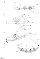
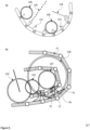
- FIG. 1 The general view of a Personal mobility vehicle 1 is presented on Figure 1 in one of its general embodiments.
- the vehicle relies on a Standing platform 3, a Guiding device 4, Optional seat 5 and Motor or pedals 7. Its main part is composed of Variable flexibility tracks 2 in contact with the ground.
- Controlling rollers 6 can change the track's rigidity from flexible to rigid and back. They can also change the track's curvature. Mobile vehicle lean on the tracks with Controlling rollers 6. The radius of a "wheel part" of the track curvature can be varied by the Controlling rollers 6 for example by the distance between those rollers. Most of the functionality is provided by those tracks and rollers.
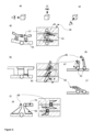
- the Standing platform 3 and the Variable flexibility tracks 2 are presented more in detail in Figure 2a that illustrates the principle of the invention.
- the Direction of motion 9 indicates the possible direction in which the vehicle advances.
- the Variable flexibility track 2 has four consecutive states of operation.
- the first state is a Locking mechanism 14 is where the track is switched from a flexible to a rigid state and remains in the rigid state.
- the operation of switching is performed by the Controlling roller 18 in locking mode (when rotating clockwise).
- the track remains rigid during the second state which is a Rigid state 15 where it plays a role of a wheel and is essential to the operation of the vehicle.
- the track enters into the third state which is an Unlocking state 16 where the operation of switching is done by Controlling roller 19 in unlocking mode where the track is switched back from a rigid state to a flexible state and continues in the fourth an last state which is the Flexible state 17, and so on.
- Unlocking state 16 the operation of switching is done by Controlling roller 19 in unlocking mode where the track is switched back from a rigid state to a flexible state and continues in the fourth an last state which is the Flexible state 17, and so on.
- the roles of rollers is inversed.
- the first one is a track locking mechanism that can be realized in various embodiments which will be shown in detail below.
- the second is a roller that plays both the locking and the unlocking role, the contact role, the guiding role and the traction role.
- variable flexibility tracks The goal of variable flexibility tracks is three-fold. First, it can provide a big wheel radius allowing going beyond obstacles in a smooth manner. Second, it provides comfort to use upper part of a vehicle without constraints. Third, it serves as a shock absorber. Indeed, the flexible curve based on limited flexibility of metal and joints between the track pieces produce a cumulated effect of a spring absorbing shocks. Among other benefits one can mention easier folding of a vehicle, easier maintenance and reduced weight due to the fact that variable flexibility track plays several roles and thus reduced the vehicle weight.
- the central point of the track is its ability to change from a rigid to a flexible state. This change operates on the level of track pieces which can be "locked” in certain range of positions by pairs or multiple locking mechanisms and form a rigid system.
- FIG. 3a-3.c the general principle of the locking mechanism is presented (a side view is used across figure).
- a track is in the flexible state where multiple Track elements 12 are connected by multiple Track hinges 13.
- Figure 3b shows a detailed view of two Track elements 12 that are not locked and can move in a Positive folding direction 47 and/or a Negative folding direction 48 to achieve Maximum positive folding 10 and a Maximum negative folding 11 limited by the Track hinge 13 only.
- the angle between the positive and the negative folding corresponds to an Unlocked flexibility angle range 24.
- Figure 3c shows a view off two Track elements 12 which are linked and blocked by a Locking mechanism 14 that limits the rotation of two Track elements 12 with respect to each other.
- the locking mechanism blocks the position of a Track element 12 at a certain Locked angle 31.
- the Locking mechanism 14 can have multiple steps of locking, thereby leading to various Locked angles 31. If the locking mechanisms between the multiple track elements are locked, the track will represent a semi-rigid structure of circular form with a certain curvature radius.
- the Locked angle 31 will not be fixed and will vary due to inherent flexibility of material from which elements are made, to the drift of the Track hinge 13 and the drift of the Locking mechanism 14 and the elasticity of the materials. Combined, those effects lead to a Locked flexibility angle range 25.
- Figure 3d is a general view of several Track element 12 that are locked between them.
- the semi-rigid structure is characterized by an Effective wheel curve 50 and an Effective wheel radius 51. Therefore, this semi-rigid structure can play a role of a wheel with a radius and rigidity that is controlled by the Locking mechanisms 14.
- Both properties are key to the invention which targets to obtain a foldable wheel with large radius and whose elasticity plays a role of a shock absorber.
- This curvature and radius vary because of the Locked flexibility angle range 25 and by locking the track its curvature varies in a certain range. It should be noted that locking could be positive to obtain circular curvature, but it could be also negative if it is necessary to keep track in inverted position.
- Locking mechanism 14 embodiments are presented in Figure 3a-3d , Figure 4a-4c , Figure 5a-5c , Figure 6a-6b and Figure 7a-7b .
- Figure 3a-3d Figure 4a-4c
- Figure 5a-5c Figure 6a-6b
- Figure 7a-7b Figure 7a-7b
- a Side view 40 a Top view 41 and Front view 42. All solutions above summarize the possibility to have a principle of the "big wheel" realized with tracks.
- FIG. 4a-4c Three configurations of locking mechanism of a sliding type are presented on Figure 4a-4c .
- a configuration on Figure 4a is where every Track element 12 bears a Locking element 30 that can move along a Guiding rail 28, have a form that completes a Fixed hook 29 and can enter into a rigid configuration of Locked position 27 with a Fixed hook 29 on another Track element 12.
- the Locking element 30 When the Locking element 30 is in a central Locked position 27 it hooks to a Fixed hook 29 and makes two Track element 12 locked to each other.
- the Locking element 30 is moved aside to an Unlocked position 26, the two Track element 12 are not locked any more and can move freely around the Track hinge 13 thus putting the track in its usual foldable state.
- the Locking element 30 also prevents that Track element 12 moves in the direction of Negative folding direction 48.
- a configuration on Figure 4b is similar to the previous solution. The difference resides in the fact that three Track element 12 are locked together.
- one Track element 12 bears a Fixed element with holes 61 that is firmly fixed to the Track element 12 and has one or several Multiple locking hole 63.
- the second track element bears a Sliding element with rod 60 that moves along a Guiding rail 28 and has a Rod 62. At different angles between the two track elements, the Sliding element with rod 60 can move along the Guiding rail 28 and lock the two track elements by positioning the Rod 62 in one Multiple locking hole 63. The selected hole defines the angle between the two track elements.
- the Sliding element with rod 60 In an unlocked state, the Sliding element with rod 60 is in an Unlocked position 26 and the Track element 12 can move in the positive and the negative folding directions.
- Figure 5c shows a configuration where one track element bears a Fixed hook 68 and a second track element bears a Locking hook 69 that have a Rotating latch 70 that has one or more holes.
- the Rotating latch 70 When the Rotating latch 70 is in the Unlocked position 26, the two track elements can move freely.
- Rotating latch 70 When Rotating latch 70 is in the Locked position 27 the Rotating latch 70 rotates until its hole coincides with the Fixed hook 68 and the two track elements are in the locked position with respect to each other.
- Figure 6a shows an embodiment where a Track element 12 rotates around Track hinge 13 and can be locked by a second chain also composed of an Element of second chain 74 with an Opening 75 rotating around a Hinge of second chain 73.
- the first main chain bears Forward pointing hook 76 and Backward pointing hook 77.
- To reach a locking position two elements of the first chain are folded so that tips of the two hooks of adjacent elements align and can be passed into the Opening 75 of the Element of second chain 74 by lowering the second chain on the first. Then by unfolding the two elements of the track tips of the two hooks are locked in the Opening 75 due to their form and are set in a locked position.
- the Opening 75 thas several separated holes, locking is possible at various angles and at negative folding as well (e.g. necessary to keep the track having a specific form on it upper side with respect to rollers).
- Figure 6b shows an embodiment where the track elements contains the same Forward pointing hook 76 and Backward pointing hook 77.
- the second upper chain contains a locking element being a Dovetail hook 78 to keep the track elements in a locked position. It operates in a similar way as the previous solution.
- the two elements of the track need to be folded to align two hooks and let them enter into the Dovetail hook 78 of the second chain by lowering it. Once done, the track elements unfolds and lock themselves reaching the situation shown on the figure where two hooks of the first main chain are locked in the Dovetail hook 78 of the second chain.
- the form of Dovetail hook 78 also prevents negative folding.
- FIG. 7a and Figure 7b two other embodiments are presented.
- a locking mechanism is placed inside a hinge linking two Track elements 12 that have each half of a Cylindrical part of hinge 84.
- the cylindrical parts rotate around an Axis with tips 85 that rotates in an Axis space 86 and can also shift in the direction of its axis of rotation.
- the Axis with tips 85 contains a First tip on axis 79 that is positioned in a First locking hole 87 of the first cylindrical part of the first track element and can only shift in axis direction but not rotate. Therefore the Axis with tips 85 and first that track element can not rotate with respect to each other.
- the axis also contains a Second tip on axis 80 that can freely move in a Corridor of rotation 88 which represent a wider space over 360 degrees around the axis.
- the Corridor of rotation 88 allows the cylindrical part of the second hinge to rotate around the axis.
- a Second tip on axis 80 is aligned with a Second locking hole 89 that is present in the Axis space 86 at certain angle only (as First tip on axis 79).
- the Axis with tips 85 can then be shifted to a position where the First locking hole 87 coincides with the Second locking hole 89.
- the Axis with tips 85 is then locked with respect to both cylindrical parts of the hinge.
- the two track elements and the axis become a rigid system where elements stay at a defined angle with respect to each other.
- Multiple Second locking holes 89 can provide multiple locking angles of the track elements. Shifting of the Axis with tips 85 can be reached by mechanically shifting as in clutch, or using contactless force (f.ex. Magnetic). In the latter case axis is more protected from dust.
- the first track element contains a Cogwheel 93 and the second track element contains a Cog 91.
- the Cog 91 advances and rotates the Cogwheel 93 around an Axis 92.
- a Spring for clutch 94 is in contact with Cogwheel 93 and allows its rotation in one direction only.
- a Locking clutch 95 prevents the Cog 91 to advance beyond certain limit and locks the two track elements at specific angle because the Spring for clutch 94 prevents the Cogwheel 93 from backward rotation. To unlock the system and return to flexible folding of the track elements, the Spring for clutch 94 should be moved aside.
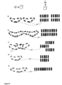
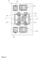
- FIG. 8 Various embodiments of tracks assemblies are illustrated on Figure 8 .
- the number of tracks is four and they provide four Contact point with the ground 107 as in a normal four-wheel car or a motorcycle.
- Four-point contact provides maximum stability for necessary maneuvers that will be performed.
- Each track is guided by two rollers resulting eight rollers.
- a second embodiment shown on Figure 8b illustrates a combination of two tracks, but involves still eight rollers and still deliver four points of contact.
- Third embodiment is shown on Figure 8c where three tracks are involved and three Contact point with the ground 107 are achieved. This configuration is less stable that four point of contact.
- Fourth embodiment shown on Figure 8d features two tracks with two Contact point with the ground 107 are used.
- An Encoding roller for track 126 positions adjacent track elements at specified angle with respect to each other and a specified position with respect to a locking chain.
- An Encoding roller for chain 127 positions the chain so that an Element of second chain 74 position and angle allows that a Forward pointing hook 76 and a Backward pointing hook 77 can enter into an Opening 75 of the locking chain coinciding with track hooks.
- the locking occurs by lowering the chain on the track to overlay opening on the hooks and further unfolding of the track with a Lean roller for track 125 and a Guiding roller for chain 124. The correct locking occurs at specific position of two rollers.
- a top view of the rollers positions is explained on Figure 10 .
- the Encoding roller for track 126 and the Encoding roller for chain 127 are positioned so that to achieve locking effect.
- Track elements and their Forward pointing hook 76 and Backward pointing hook 77 are positioned with respect to the Element of second chain 74 so that they can enter into the Opening 75 at a specific time.
- the Guiding roller for chain 124 unfold the locking chain and when the Lean roller for track 125 is in contact with rigidly locked track elements, it's already a rigid system.
- a Roller 120 (or system of rollers as explained above) can set the angle of locking mechanism for every pair of track elements from a Locking mechanism position one 121 to a Locking mechanism position two 122 (and vice versa depending on the direction of motion).
- the combined effect of angles between individual track elements is the change of a curvature of the track from a Larger radius 118 to a Smaller radius 119.
- a change of curvature occurs in various embodiments adapted for each locking mechanism.
- a first embodiment is that track does not change and bears a Forward pointing hook 76 and a Backward pointing hook 77 but angle at which they are blocked is controlled by the Opening 75 of locking chain.
- the Element of second chain 74 could have openings of several sizes that would block hooks of the track at different angles. Size of such openings are controlled for example by sliding elements reducing the opening or that opening has various gradations of gaps and by positioning the locking chain hooks are locked at desired angles.
- Another embodiment is where opening remains the same, but hooks have several steps at different heights which with same opening of locking chain would correspond to different angles of locking between track elements.
- the advantage of the second embodiment is a difference in lever allowing to lock track elements at more open angles with bigger lever (where more force is needed) and at higher curvatures (where less force is needed) the lever is smaller.
- the original track form is a High curvature with small radius 143 and track is locked at its Big radius of low curvature 148.
- This configuration provides that position is Platform height at low curvature 157 above the ground.
- the result of the operation is a Low curvature with big radius 142 where track is locked at its Small radius of high curvature 149 and Platform height at high curvature 158 above the ground.
- the platform changes its height above the ground by a Height difference 159 between two states of high and low track curvature. Changing height of the platform or one of the tracks provides very useful functionality in various drivability scenarios.
- a transitions between a Low curvature with big radius 142 and a High curvature with small radius 143 occurs across one half-cycle of track rotation around rollers.
- a Controlling roller 18 starts to change the curvature of the track.
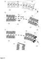
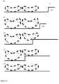
- Intermediate states of the track are shown on Figure 11a, Figure 11b and Figure 11c. In each of those states the track has one part of low curvature and one part of high curvature separated by a Joint point 144.
- a curvature decrease effect shown on Figure 11b has a reverse effect. Let's assume that motion occurs in the same direction. The track goes from a High curvature with small radius 143 to a Low curvature with big radius 142 and the radius goes from a Small radius of high curvature 149 to a Big radius of low curvature 148. Subsequently platform (or track alone) goes from bigger height to lower height.
- the operation of change goes through intermediate states: Intermediate track state four 173, Intermediate track state five 174.
- a forward roller first changes the curvature of the Joint point 144 with given angle between track elements and continues to do so at High curvature with small radius 143.
- achieving smoothness between two circular parts of the track with different radiuses is unlikely and a Tangent bigger curvature 145 and a Tangent smaller curvature 146 can not be equal because of negative angle.
- the track gradually passes from a Intermediate track state four 173 to an Intermediate track state five 174 and at the end to a Low curvature with big radius 142.
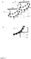
- the Figure 12a-c explains three various turning options for a vehicle where three turning methods are present. For each method a Position before turning 136 and a Position after turning 137 are shown as well as a Rotating trajectory 139.
- a first turning method shown in Figure 12a implies configuration of four tracks or two tracks one after another as shown in the Position before turning 136.
- the forward pair of tracks or First pair of track rotates 133 turns to follow the Rotating trajectory 139 as a normal four-wheel car would do.
- a second turning method shown in shown in Figure 12b implies that at the Position before turning 136 the Speed of outer track 134 becomes higher respectively to Speed of inner track 135. Therefore, Position after turning 137 follows the Rotating trajectory 139 similar to tanks.
- a third turning method shown in shown in Figure 12c implies that at the Position before turning 136 the two tracks deform in the direction Rotating trajectory 139 to reach Deformed curved state 138. This can be achieved with Additional hinges 190 between the track elements.
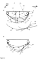
- the Figure 13a-e explain the use of track curvature change to overcome boardwalk steps in a city.
- the four track configuration (seen from the side) moves in Direction of motion 9 where it approaches a Sidewalk step 105. View is fixed on the tracks meaning that ground moves leftwards.
- both tracks change their curvature to heighten the position of the platform before touching Sidewalk step 105.
- the first track starts to change its curvature to normal.
- the first track is now present on the Sidewalk step 105 level with normal curvature and the second track is at lower level with its higher curvature.
- the second track follows the same behavior as the first one and ends on Sidewalk step 105 with the lower curvature.
- the Figure 14 explains the way a platform of four tracks can optionally move on stairs.
- tracks can change curvature and lift rear part of the platform to maintain the driver at best possible horizontal orientation with respect to stairs inclination.
- the most comfortable solution seems, however, to be achieved with a mode illustrated on the figure where a platform splits into a section First section 187 and a Second section 188.
- the two tracks At the moment of reaching a stairs the two tracks (on one side) achieve four Contact point with staircase 150.
- the Lifting step of first section 151 raises as well as the Lifting step of second section 153.
- the Extending floor 152 bridges the space between two sections at the same way as escalator.
- the platform remains horizontal and composed of two sections.
- the track elements can have a Low grip 154 and High grip 155 making Contact gripping point 156 much more stable (shown on lower part of the figure).
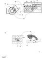
- the Figure 15a-b show some optional comfort elements of the invention.
- the platform remains flat for the driver and the luggage.
- the Motor 162 is beneath the platform.
- an option is to have the Battery 164 located directly below the platform near the motor or in the track elements. This would make the weight supported by tracks and rollers lower.
- the Pedals 167 remain in front and can be connected to front roller with changing speeds.
- the Guiding pad 168 allows controlling direction of the vehicle, changing gears, a reverse motion, making the vehicle rotate around its vertical axis, etc.
- An Umbrella 165 or holder for normal umbrella would protect from rain and can be attached to the same vertical stand as the control pad or be more towards rear of the vehicle (and be foldable).
- the Seat 163 can be foldable and allow luggage beneath. Additional elements like Barrier 166 to lean upon can be provided.
- the vehicle can contain usual elements like lights, etc.
- the front lights would include laser pointers projecting lines and curves on the ground, said lines and curves indicating the trajectory of the vehicle and its dimensions corridor. With two curves lines on the ground, driver can have a clear understanding where the vehicle is advancing and if it passes between two trees and if its turn trajectory is compatible with obstacles.
Landscapes
- Engineering & Computer Science (AREA)
- Mechanical Engineering (AREA)
- Chemical & Material Sciences (AREA)
- Combustion & Propulsion (AREA)
- Transportation (AREA)
- Motorcycle And Bicycle Frame (AREA)
- Toys (AREA)
Claims (9)
- Système mobile comprenant au moins une piste à flexibilité variable (2) et au moins deux rouleaux (6, 18, 19) autour desquels la piste à flexibilité variable est enroulée, dans lequel les rouleaux sont adaptés pour modifier la rigidité et la courbure de la piste à flexibilité variable afin de modifier sa forme de manière à ce qu'elle soit une roue ou qu'elle ait une partie correspondant à une roue circulaire avec une courbure différente ou qu'elle soit pliable, ladite piste à flexibilité variable étant composée de :- une pluralité d'éléments de voie (12) et des charnières (13) reliant ladite pluralité d'éléments de voie de manière à permettre la rotation des éléments de voie les uns par rapport aux autres autour des charnières, et- un mécanisme de verrouillage (14) sur chaque élément de la voie qui permet de verrouiller une position des éléments de la voie par rapport aux éléments adjacents à différents angles ; et lesdits rouleaux étant en contact avec la voie à flexibilité variable et comprenant au moins l'un des éléments suivants- un mécanisme qui interagit avec le mécanisme de verrouillage (14) de chaque élément de voie (12) pour modifier la rigidité de la voie à flexibilité variable (2) qui peut être présente dans la voie à flexibilité variable à l'intérieur des rouleaux,- un mécanisme permettant de modifier la courbure ou la position relative des chenilles afin de permettre la navigation dans les escaliers et le franchissement d'autres obstacles,- un mécanisme permettant de diriger le système mobile en appliquant une vitesse et/ou une courbure différente aux pistes.
- Le système mobile selon la revendication 1, dans lequel les rouleaux (6, 18, 19) sont des éléments de guidage des chenilles et peuvent bloquer les éléments de chenille (12) entre eux en fonction de la direction du mouvement et à différents angles résultant d'une courbure variée de la chenille à flexibilité variable (2).
- Le système mobile selon l'une quelconque des revendications précédentes, adapté pour produire une courbure donnée élément rigide circulaire sur la partie inférieure de la piste qui correspond à une roue, tandis que la partie supérieure de la piste reste souple et n'occupe pas l'espace au-dessus des rouleaux.
- Le système mobile selon l'une des revendications précédentes, qui est composé de différentes configurations de pistes comprenant une piste pour un mouvement de type "skate", deux pistes pour une navigation de type "segway", trois ou quatre pour un mouvement plus stable comme dans une plate-forme personnelle ou un véhicule de type voiture ou plus de pistes.
- Véhicule de mobilité personnelle (1) comprenant le système mobile selon l'une des revendications précédentes, combiné aux éléments suivants :- une plate-forme (3) en matériau rigide en contact avec des rouleaux pour supporter la charge opérationnelle du véhicule, ladite plate-forme étant en contact avec les rouleaux ;- un mécanisme d'activation de la propulsion, tel qu'un moteur, des pédales ou un mécanisme d'activation électrique ;- un pavé de commande de guidage (168) sur un support rigide permettant de contrôler le véhicule ;- un ensemble d'éléments de confort optionnels (163) tels que quatre sièges ou plus, un toit pliant de type parapluie et des bagages ;- des indicateurs laser qui projettent sur la route des motifs laser correspondant à la trajectoire attendue du véhicule et à la distance de freinage possible.
- Véhicule de mobilité personnelle selon la revendication 5, dans lequel le mécanisme de rotation du véhicule est réalisé en tournant au moins une partie des chenilles, en modifiant la vitesse des chenilles du côté extérieur de la rotation ou en déformant les chenilles pour former une courbe.
- Véhicule de mobilité personnelle selon la revendication 5 ou 6, dans lequel le mécanisme de navigation dans les escaliers pour véhicule personnel est réalisé en changeant la courbure des voies ou en changeant la forme d'une plate-forme.
- Véhicule de mobilité personnelle selon l'une quelconque des revendications précédentes, où si le moteur est électrique, les batteries de ce moteur peuvent être situées n'importe où dans le véhicule, y compris à l'intérieur des éléments de la voie pour réduire le poids sur les rouleaux.
- Méthode de pilotage du véhicule de mobilité personnelle des revendications 5 à 8 avec des moyens informatiques, ladite méthode comprenant les étapes suivantes :- calculer la position, la vitesse, l'inclinaison, le type d'obstacle à venir et la position de l'utilisateur par rapport audit véhicule de mobilité personnelle, sur la base de capteurs,- adapter la géométrie, la courbure, la vitesse et la forme de la plate-forme pour franchir les obstacles du véhicule de mobilité personnelle ;- l'application de la configuration nécessaire pour alléger la navigation sur le terrain marécageux à l'aide dudit véhicule à mobilité personnelle, et- projeter sur la route des motifs laser indiquant la trajectoire prévue du véhicule afin d'informer l'utilisateur de la faisabilité de telle ou telle trajectoire et de la distance de freinage.
Applications Claiming Priority (2)
| Application Number | Priority Date | Filing Date | Title |
|---|---|---|---|
| IB2016001732 | 2016-12-05 | ||
| PCT/IB2017/001476 WO2018104770A2 (fr) | 2016-12-05 | 2017-11-29 | Véhicule à mobilité à chenille en forme de glissière |
Publications (3)
| Publication Number | Publication Date |
|---|---|
| EP3548367A2 EP3548367A2 (fr) | 2019-10-09 |
| EP3548367B1 true EP3548367B1 (fr) | 2025-02-26 |
| EP3548367C0 EP3548367C0 (fr) | 2025-02-26 |
Family
ID=62200480
Family Applications (1)
| Application Number | Title | Priority Date | Filing Date |
|---|---|---|---|
| EP17872897.8A Active EP3548367B1 (fr) | 2016-12-05 | 2017-11-29 | Véhicule à mobilité à chenille en forme de glissière |
Country Status (3)
| Country | Link |
|---|---|
| US (1) | US11345421B2 (fr) |
| EP (1) | EP3548367B1 (fr) |
| WO (1) | WO2018104770A2 (fr) |
Families Citing this family (2)
| Publication number | Priority date | Publication date | Assignee | Title |
|---|---|---|---|---|
| DE102019209620A1 (de) | 2019-07-01 | 2021-01-07 | Rud Ketten Rieger & Dietz Gmbh U. Co. Kg | Gleitschutzkette mit Verdrehsperre |
| DE102021004436A1 (de) | 2021-09-01 | 2023-03-02 | Torsten Fette | Elektrisches Transportmittel mit einer Vorrichtung zur Lastenaufnahme |
Family Cites Families (7)
| Publication number | Priority date | Publication date | Assignee | Title |
|---|---|---|---|---|
| US1674133A (en) * | 1924-06-25 | 1928-06-19 | Moore And Moore Inc | Endless tread |
| US1868148A (en) * | 1930-06-09 | 1932-07-19 | Mcmillan Miller Road Machinery | Track link |
| US2371802A (en) * | 1943-05-20 | 1945-03-20 | Frederick W Chriswell | Endless traction belt |
| GB584239A (en) | 1944-12-21 | 1947-01-09 | Roadless Traction Ltd | Improvements in and relating to vehicular endless tracks of the "locked girder" type |
| US3056633A (en) | 1959-08-06 | 1962-10-02 | Lok Trak Inc | Traction chain and wheel assemblies |
| US3179431A (en) * | 1963-01-29 | 1965-04-20 | Otto G Pikl | Obstacle-climbing wheel chairs |
| IL122062A (en) | 1997-10-29 | 2000-08-13 | Galileo Mobility Instr Ltd | Transporting system |
-
2017
- 2017-11-29 EP EP17872897.8A patent/EP3548367B1/fr active Active
- 2017-11-29 US US16/466,538 patent/US11345421B2/en active Active
- 2017-11-29 WO PCT/IB2017/001476 patent/WO2018104770A2/fr not_active Ceased
Also Published As
| Publication number | Publication date |
|---|---|
| EP3548367A2 (fr) | 2019-10-09 |
| WO2018104770A2 (fr) | 2018-06-14 |
| US11345421B2 (en) | 2022-05-31 |
| WO2018104770A3 (fr) | 2018-09-27 |
| US20190291794A1 (en) | 2019-09-26 |
| EP3548367C0 (fr) | 2025-02-26 |
Similar Documents
| Publication | Publication Date | Title |
|---|---|---|
| US20240326944A1 (en) | Dynamically balanced in-line wheel vehicle | |
| EP2062808B1 (fr) | Vehicule avec deux roues paralleles | |
| CN105593044B (zh) | 可倾斜的三轮车辆 | |
| CN105857423B (zh) | 一种高机动高适应性地面无人平台 | |
| Brown et al. | A single-wheel, gyroscopically stabilized robot | |
| US8818700B2 (en) | Motorised vehicle with controlled inclination | |
| CN101596836B (zh) | 一种具有变径轮子的越障机器人 | |
| CN107529434B (zh) | 履带式移动机构 | |
| JP6003712B2 (ja) | キャスター式の後輪を備えた小型移動体 | |
| CN108024895B (zh) | 轮子与履带混合式移动机构 | |
| JP2011513119A (ja) | 制御される傾きをもつ原動機付き車両 | |
| EP3548367B1 (fr) | Véhicule à mobilité à chenille en forme de glissière | |
| JP2017518226A (ja) | 車台および振子ゴンドラを備えた乗り物 | |
| JP2001511092A (ja) | 道路車両の車軸のための少なくとも1本の路面レールにそった誘導システム | |
| CN105799838A (zh) | 折叠自行包 | |
| CA2672928A1 (fr) | Systemes et vehicules pour le transport de personnes et de marchandises | |
| CN203601479U (zh) | 两车轮随转向倾斜的自平衡车 | |
| CN205345242U (zh) | 折叠自行包 | |
| FR2640220A1 (fr) | Vehicule articule bidirectionnel guidable, notamment autobus articule | |
| JP2009113782A (ja) | 多輪タイヤキャスター及び無回転軸キャスター | |
| WO2018017040A1 (fr) | Tricycle transformable | |
| CN201161674Y (zh) | 承载转盘控向式代步车辆 | |
| WO2015165501A1 (fr) | Arrangement de roulette orientable | |
| CN109018069A (zh) | 轮式移动平台及移动小车 | |
| CN207550383U (zh) | 自动站立装置及其具有自动站立装置的偏摆式车辆 |
Legal Events
| Date | Code | Title | Description |
|---|---|---|---|
| STAA | Information on the status of an ep patent application or granted ep patent |
Free format text: STATUS: THE INTERNATIONAL PUBLICATION HAS BEEN MADE |
|
| PUAI | Public reference made under article 153(3) epc to a published international application that has entered the european phase |
Free format text: ORIGINAL CODE: 0009012 |
|
| STAA | Information on the status of an ep patent application or granted ep patent |
Free format text: STATUS: REQUEST FOR EXAMINATION WAS MADE |
|
| 17P | Request for examination filed |
Effective date: 20190620 |
|
| AK | Designated contracting states |
Kind code of ref document: A2 Designated state(s): AL AT BE BG CH CY CZ DE DK EE ES FI FR GB GR HR HU IE IS IT LI LT LU LV MC MK MT NL NO PL PT RO RS SE SI SK SM TR |
|
| AX | Request for extension of the european patent |
Extension state: BA ME |
|
| DAV | Request for validation of the european patent (deleted) | ||
| DAX | Request for extension of the european patent (deleted) | ||
| STAA | Information on the status of an ep patent application or granted ep patent |
Free format text: STATUS: EXAMINATION IS IN PROGRESS |
|
| 17Q | First examination report despatched |
Effective date: 20200703 |
|
| GRAP | Despatch of communication of intention to grant a patent |
Free format text: ORIGINAL CODE: EPIDOSNIGR1 |
|
| STAA | Information on the status of an ep patent application or granted ep patent |
Free format text: STATUS: GRANT OF PATENT IS INTENDED |
|
| INTG | Intention to grant announced |
Effective date: 20240918 |
|
| GRAS | Grant fee paid |
Free format text: ORIGINAL CODE: EPIDOSNIGR3 |
|
| GRAA | (expected) grant |
Free format text: ORIGINAL CODE: 0009210 |
|
| STAA | Information on the status of an ep patent application or granted ep patent |
Free format text: STATUS: THE PATENT HAS BEEN GRANTED |
|
| AK | Designated contracting states |
Kind code of ref document: B1 Designated state(s): AL AT BE BG CH CY CZ DE DK EE ES FI FR GB GR HR HU IE IS IT LI LT LU LV MC MK MT NL NO PL PT RO RS SE SI SK SM TR |
|
| REG | Reference to a national code |
Ref country code: GB Ref legal event code: FG4D |
|
| REG | Reference to a national code |
Ref country code: CH Ref legal event code: EP |
|
| REG | Reference to a national code |
Ref country code: DE Ref legal event code: R096 Ref document number: 602017088058 Country of ref document: DE |
|
| REG | Reference to a national code |
Ref country code: IE Ref legal event code: FG4D |
|
| U01 | Request for unitary effect filed |
Effective date: 20250312 |
|
| U07 | Unitary effect registered |
Designated state(s): AT BE BG DE DK EE FI FR IT LT LU LV MT NL PT RO SE SI Effective date: 20250320 |
|
| PG25 | Lapsed in a contracting state [announced via postgrant information from national office to epo] |
Ref country code: RS Free format text: LAPSE BECAUSE OF FAILURE TO SUBMIT A TRANSLATION OF THE DESCRIPTION OR TO PAY THE FEE WITHIN THE PRESCRIBED TIME-LIMIT Effective date: 20250526 |
|
| PG25 | Lapsed in a contracting state [announced via postgrant information from national office to epo] |
Ref country code: PL Free format text: LAPSE BECAUSE OF FAILURE TO SUBMIT A TRANSLATION OF THE DESCRIPTION OR TO PAY THE FEE WITHIN THE PRESCRIBED TIME-LIMIT Effective date: 20250226 |
|
| PG25 | Lapsed in a contracting state [announced via postgrant information from national office to epo] |
Ref country code: ES Free format text: LAPSE BECAUSE OF FAILURE TO SUBMIT A TRANSLATION OF THE DESCRIPTION OR TO PAY THE FEE WITHIN THE PRESCRIBED TIME-LIMIT Effective date: 20250226 |
|
| PG25 | Lapsed in a contracting state [announced via postgrant information from national office to epo] |
Ref country code: NO Free format text: LAPSE BECAUSE OF FAILURE TO SUBMIT A TRANSLATION OF THE DESCRIPTION OR TO PAY THE FEE WITHIN THE PRESCRIBED TIME-LIMIT Effective date: 20250526 Ref country code: IS Free format text: LAPSE BECAUSE OF FAILURE TO SUBMIT A TRANSLATION OF THE DESCRIPTION OR TO PAY THE FEE WITHIN THE PRESCRIBED TIME-LIMIT Effective date: 20250626 |
|
| PG25 | Lapsed in a contracting state [announced via postgrant information from national office to epo] |
Ref country code: HR Free format text: LAPSE BECAUSE OF FAILURE TO SUBMIT A TRANSLATION OF THE DESCRIPTION OR TO PAY THE FEE WITHIN THE PRESCRIBED TIME-LIMIT Effective date: 20250226 |
|
| PG25 | Lapsed in a contracting state [announced via postgrant information from national office to epo] |
Ref country code: GR Free format text: LAPSE BECAUSE OF FAILURE TO SUBMIT A TRANSLATION OF THE DESCRIPTION OR TO PAY THE FEE WITHIN THE PRESCRIBED TIME-LIMIT Effective date: 20250527 |
|
| PG25 | Lapsed in a contracting state [announced via postgrant information from national office to epo] |
Ref country code: SM Free format text: LAPSE BECAUSE OF FAILURE TO SUBMIT A TRANSLATION OF THE DESCRIPTION OR TO PAY THE FEE WITHIN THE PRESCRIBED TIME-LIMIT Effective date: 20250226 |
|
| PG25 | Lapsed in a contracting state [announced via postgrant information from national office to epo] |
Ref country code: CZ Free format text: LAPSE BECAUSE OF FAILURE TO SUBMIT A TRANSLATION OF THE DESCRIPTION OR TO PAY THE FEE WITHIN THE PRESCRIBED TIME-LIMIT Effective date: 20250226 |
|
| PG25 | Lapsed in a contracting state [announced via postgrant information from national office to epo] |
Ref country code: SK Free format text: LAPSE BECAUSE OF FAILURE TO SUBMIT A TRANSLATION OF THE DESCRIPTION OR TO PAY THE FEE WITHIN THE PRESCRIBED TIME-LIMIT Effective date: 20250226 |
|
| U20 | Renewal fee for the european patent with unitary effect paid |
Year of fee payment: 9 Effective date: 20251006 |
|
| PLBE | No opposition filed within time limit |
Free format text: ORIGINAL CODE: 0009261 |
|
| STAA | Information on the status of an ep patent application or granted ep patent |
Free format text: STATUS: NO OPPOSITION FILED WITHIN TIME LIMIT |
|
| 26N | No opposition filed |
Effective date: 20251127 |