EP3548728B1 - Verfahren zur steuerung eines turbokompressors zur aufladung für eine brennkraftmaschine - Google Patents
Verfahren zur steuerung eines turbokompressors zur aufladung für eine brennkraftmaschine Download PDFInfo
- Publication number
- EP3548728B1 EP3548728B1 EP17816988.4A EP17816988A EP3548728B1 EP 3548728 B1 EP3548728 B1 EP 3548728B1 EP 17816988 A EP17816988 A EP 17816988A EP 3548728 B1 EP3548728 B1 EP 3548728B1
- Authority
- EP
- European Patent Office
- Prior art keywords
- engine
- geometry
- compressor
- turbine
- adjustment
- Prior art date
- Legal status (The legal status is an assumption and is not a legal conclusion. Google has not performed a legal analysis and makes no representation as to the accuracy of the status listed.)
- Active
Links
Images

Classifications
-
- F—MECHANICAL ENGINEERING; LIGHTING; HEATING; WEAPONS; BLASTING
- F02—COMBUSTION ENGINES; HOT-GAS OR COMBUSTION-PRODUCT ENGINE PLANTS
- F02D—CONTROLLING COMBUSTION ENGINES
- F02D41/00—Electrical control of supply of combustible mixture or its constituents
- F02D41/0002—Controlling intake air
- F02D41/0007—Controlling intake air for control of turbo-charged or super-charged engines
-
- F—MECHANICAL ENGINEERING; LIGHTING; HEATING; WEAPONS; BLASTING
- F02—COMBUSTION ENGINES; HOT-GAS OR COMBUSTION-PRODUCT ENGINE PLANTS
- F02B—INTERNAL-COMBUSTION PISTON ENGINES; COMBUSTION ENGINES IN GENERAL
- F02B39/00—Component parts, details, or accessories relating to, driven charging or scavenging pumps, not provided for in groups F02B33/00 - F02B37/00
- F02B39/005—Cooling of pump drives
-
- F—MECHANICAL ENGINEERING; LIGHTING; HEATING; WEAPONS; BLASTING
- F02—COMBUSTION ENGINES; HOT-GAS OR COMBUSTION-PRODUCT ENGINE PLANTS
- F02D—CONTROLLING COMBUSTION ENGINES
- F02D41/00—Electrical control of supply of combustible mixture or its constituents
- F02D41/02—Circuit arrangements for generating control signals
- F02D41/04—Introducing corrections for particular operating conditions
- F02D41/045—Detection of accelerating or decelerating state
-
- F—MECHANICAL ENGINEERING; LIGHTING; HEATING; WEAPONS; BLASTING
- F02—COMBUSTION ENGINES; HOT-GAS OR COMBUSTION-PRODUCT ENGINE PLANTS
- F02D—CONTROLLING COMBUSTION ENGINES
- F02D41/00—Electrical control of supply of combustible mixture or its constituents
- F02D41/02—Circuit arrangements for generating control signals
- F02D41/04—Introducing corrections for particular operating conditions
- F02D41/10—Introducing corrections for particular operating conditions for acceleration
-
- F—MECHANICAL ENGINEERING; LIGHTING; HEATING; WEAPONS; BLASTING
- F02—COMBUSTION ENGINES; HOT-GAS OR COMBUSTION-PRODUCT ENGINE PLANTS
- F02D—CONTROLLING COMBUSTION ENGINES
- F02D41/00—Electrical control of supply of combustible mixture or its constituents
- F02D41/24—Electrical control of supply of combustible mixture or its constituents characterised by the use of digital means
- F02D41/2406—Electrical control of supply of combustible mixture or its constituents characterised by the use of digital means using essentially read only memories
- F02D41/2409—Addressing techniques specially adapted therefor
- F02D41/2422—Selective use of one or more tables
-
- F—MECHANICAL ENGINEERING; LIGHTING; HEATING; WEAPONS; BLASTING
- F02—COMBUSTION ENGINES; HOT-GAS OR COMBUSTION-PRODUCT ENGINE PLANTS
- F02B—INTERNAL-COMBUSTION PISTON ENGINES; COMBUSTION ENGINES IN GENERAL
- F02B37/00—Engines characterised by provision of pumps driven at least for part of the time by exhaust
- F02B37/12—Control of the pumps
- F02B37/18—Control of the pumps by bypassing exhaust from the inlet to the outlet of turbine or to the atmosphere
-
- F—MECHANICAL ENGINEERING; LIGHTING; HEATING; WEAPONS; BLASTING
- F02—COMBUSTION ENGINES; HOT-GAS OR COMBUSTION-PRODUCT ENGINE PLANTS
- F02B—INTERNAL-COMBUSTION PISTON ENGINES; COMBUSTION ENGINES IN GENERAL
- F02B37/00—Engines characterised by provision of pumps driven at least for part of the time by exhaust
- F02B37/12—Control of the pumps
- F02B37/24—Control of the pumps by using pumps or turbines with adjustable guide vanes
-
- F—MECHANICAL ENGINEERING; LIGHTING; HEATING; WEAPONS; BLASTING
- F02—COMBUSTION ENGINES; HOT-GAS OR COMBUSTION-PRODUCT ENGINE PLANTS
- F02D—CONTROLLING COMBUSTION ENGINES
- F02D2200/00—Input parameters for engine control
- F02D2200/02—Input parameters for engine control the parameters being related to the engine
- F02D2200/04—Engine intake system parameters
- F02D2200/0406—Intake manifold pressure
-
- F—MECHANICAL ENGINEERING; LIGHTING; HEATING; WEAPONS; BLASTING
- F02—COMBUSTION ENGINES; HOT-GAS OR COMBUSTION-PRODUCT ENGINE PLANTS
- F02D—CONTROLLING COMBUSTION ENGINES
- F02D2200/00—Input parameters for engine control
- F02D2200/02—Input parameters for engine control the parameters being related to the engine
- F02D2200/10—Parameters related to the engine output, e.g. engine torque or engine speed
- F02D2200/1002—Output torque
-
- F—MECHANICAL ENGINEERING; LIGHTING; HEATING; WEAPONS; BLASTING
- F02—COMBUSTION ENGINES; HOT-GAS OR COMBUSTION-PRODUCT ENGINE PLANTS
- F02D—CONTROLLING COMBUSTION ENGINES
- F02D2200/00—Input parameters for engine control
- F02D2200/02—Input parameters for engine control the parameters being related to the engine
- F02D2200/10—Parameters related to the engine output, e.g. engine torque or engine speed
- F02D2200/101—Engine speed
-
- F—MECHANICAL ENGINEERING; LIGHTING; HEATING; WEAPONS; BLASTING
- F02—COMBUSTION ENGINES; HOT-GAS OR COMBUSTION-PRODUCT ENGINE PLANTS
- F02D—CONTROLLING COMBUSTION ENGINES
- F02D2200/00—Input parameters for engine control
- F02D2200/60—Input parameters for engine control said parameters being related to the driver demands or status
- F02D2200/602—Pedal position
-
- Y—GENERAL TAGGING OF NEW TECHNOLOGICAL DEVELOPMENTS; GENERAL TAGGING OF CROSS-SECTIONAL TECHNOLOGIES SPANNING OVER SEVERAL SECTIONS OF THE IPC; TECHNICAL SUBJECTS COVERED BY FORMER USPC CROSS-REFERENCE ART COLLECTIONS [XRACs] AND DIGESTS
- Y02—TECHNOLOGIES OR APPLICATIONS FOR MITIGATION OR ADAPTATION AGAINST CLIMATE CHANGE
- Y02T—CLIMATE CHANGE MITIGATION TECHNOLOGIES RELATED TO TRANSPORTATION
- Y02T10/00—Road transport of goods or passengers
- Y02T10/10—Internal combustion engine [ICE] based vehicles
- Y02T10/12—Improving ICE efficiencies
Definitions
- the present invention relates generally to the field of the control of supercharging systems of internal combustion engines by turbocharger comprising a variable geometry compressor.
- a turbocharger is composed of a turbine and a compressor driven in rotation by the turbine, through a shaft connecting the turbine to the compressor.
- the turbine is arranged in an engine exhaust circuit in the path of the exhaust gases and is rotated by the exhaust gases.
- the compressor is disposed in an intake circuit on the air intake path in the engine. It compresses the air injected into the engine, allowing the engine to be supercharged with respect to intake rpm at atmospheric pressure.
- the power taken by the exhaust gas turbine can advantageously be modulated by providing movable fins with variable orientation at the level of the turbine inlet, making it possible to modify the geometry of the turbine so as to influence the flow of exhaust gas on the turbine. This is called a variable geometry turbine.
- the power supplied by the compressor can also be modulated by arranging fins with variable orientation at the inlet or at the outlet of the compressor. We talk about variable geometry compressor.
- Actuators are provided to control the opening and closing of the variable orientation fins, which respectively equip the turbine and the compressor.
- the control signals for these actuators are provided by an electronic engine control unit (ECU) as a function of engine speed and torque, so as to control the pressure in the engine intake manifold.
- ECU electronic engine control unit
- the document FR 2 915 237 A1 describes the control of a supercharging turbocharger adjusting the geometry of a variable geometry compressor, during which a modification of the setting of the geometry of the compressor corresponding to an optimized efficiency of the compressor for a transient operation of the engine is ordered.
- variable geometry compressor systems as described above are generally adjusted to optimize engine performance during these stabilized phases, or even to reduce vehicle consumption and pollutant emissions during operating phases. at partial load. However, during a transient phase, the performance of the engine is lower than the load level that the engine would have in the stabilized phase, due to the time it takes for the supercharging system to activate.
- one switches progressively from the second map to the first map when the engine torque is at least equal to 90% of the maximum torque level obtained when the engine speed is stabilized.
- the detection of the transient operation of the engine comprises the comparison with a predefined threshold of the evolution over time of the degree of depression of the accelerator pedal associated with the engine.
- the transient operation is detected when the derivative with respect to time of the degree of depression of the accelerator pedal is greater than the predefined threshold.
- the adjustment values of the geometry of the compressor mapped in the first and second mappings make it possible to adjust the orientation of the variable-orientation fins fitted to the compressor, the adjustment values of the second mapping being adapted to control a position of. greater opening of the fins than the adjustment values of the first map according to the engine speed.
- the turbine of the turbocharger being a variable-geometry turbine equipped with variable-orientation fins
- the orientation of the control fins is adjusted.
- the turbine in a closed position of the fins and a richness setpoint is developed for the engine corresponding to the maximum richness permissible by the engine, as long as the pressure measured in the engine intake manifold is less than a setpoint pressure representative of the required boost pressure.
- the turbocharger turbine being a fixed-geometry turbine
- a discharge valve is controlled, arranged upstream of the inlet of the compressor. the turbine, in a closed position, so as to pass all the exhaust gases through the turbine and a richness setpoint is developed for the engine corresponding to the maximum richness admissible by the engine, as long as the measured pressure in the engine intake manifold is less than a set pressure representative of the required boost pressure.
- the boost pressure in the intake manifold is regulated around the boost pressure required for achieve maximum torque when the engine speed is stabilized, by changing the geometry of the turbine or controlling the relief valve.
- the invention also relates to a supercharged internal combustion engine comprising a turbocharger of the type comprising a turbine and a variable geometry compressor, in which an electronic engine control unit acts on a control of the geometry of the compressor, said control unit setting implementing the method as described above.
- the invention also relates to a motor vehicle comprising an engine as described above.
- the control method of the invention applies to a variable geometry turbocharger intended to supercharge an internal combustion engine, in particular of the diesel type, fitted to a motor vehicle, of the type comprising an actuator controlled by the unit.
- electronic engine control ECU as a function of engine speed and torque, to control the opening of variable-orientation vanes placed either upstream or downstream of the compressor wheel, and which make it possible to influence the 'gas flow in the compressor wheel so as to improve aerodynamic performance and extend the operating range of the compressor.
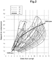
- the figure 2 illustrates different compressor fields, translating for different compressor geometries identified by the angles of the fins, the compression ratio as a function of the air flow in the compressor, the compression ratio being defined as the ratio of the air pressure leaving the compressor on the pressure of the air entering the compressor.
- the angle of 55 ° applied to the orientation of the fins corresponds to an open position of the system, while the angle of 90 ° corresponds to the most closed position, that is to say the section of passage of the gases towards the compressor wheel. the most closed. Note that the actual compressor field at a given position is an interpolation of the compressor fields at the positions closest to that position.
- the adjustment of the opening of the compressor fins is obtained so as to optimize the outputs of the compressor at constant engine speed, ie to optimize the performance of the stabilized engine.
- the figure 3 illustrates in this regard an example of a first map C1 of adjustment values of the geometry of the compressor as a function of the engine speed, corresponding to the adjustment values for the opening of the fins for which the efficiency of the compressor is optimized in stabilized operation of the engine at substantially constant engine speed.
- the figure 3 also shows a second map C2 of values for adjusting the geometry of the compressor as a function of the engine speed, corresponding to optimal settings of the variable-geometry compressor during the transient phases of the engine, that is to say during requests for strong acceleration from the driver. It appears that these settings are very different from those optimized for the stabilized full load of the engine, with in particular larger opening angles of the fins. In fact, in stabilized operation, the search for optimum performance makes it necessary to close the system in order to obtain high compression ratios, and to keep a large margin with respect to the pumping phenomenon of the compressor.
- the method of the invention therefore proposes to adjust the position of the fins of the variable-geometry compressor differently for the transient operation of the engine, by applying the second adjustment map of the opening of the fins designed to optimize the outputs of the compressor during these phases. motor transients.
- the information collected by a boost pressure sensor and a position sensor of the accelerator pedal associated with the engine is used in order to locate the load level of the engine and to detect the demand for high torque in transient operation of the engine. engine.
- the transient operation of the motor is detected, in a step E1, by the comparison with a predefined threshold of the evolution over time of the degree of depression of the pedal accelerator.
- Transient operation is for example detected when the derivative with respect to time of the degree of depression of the accelerator pedal is greater than a predefined threshold or by a torque request corresponding for example to a value greater than 90% of the maximum torque. .
- step E2 in which the position of the compressor fins is adjusted by using a first map of values for adjusting the geometry of the compressor as a function of the operating speed. engine rotation, corresponding to optimized compressor efficiency for stabilized engine operation.
- a step E3 is applied, in which one uses for the adjustment of the position of the compressor fins, a second map of values for adjusting the geometry of the compressor as a function of the speed. engine rotation, corresponding to an optimized efficiency of the compressor for transient engine operation. More particularly, this second map, used when a transient operation of the engine is detected, is suitable for controlling an opening position of the fins greater than that resulting from the adjustment values of the first map as a function of the engine speed. This second map is used as long as the torque level has not reached, for example, 90% of the maximum torque level obtained when the engine speed is stabilized. When this torque value is reached or exceeded, in a step E4, we move progressively from the second map to the first map for adjusting the position of the compressor fins and the first map will be fully used at the end of transient engine operation. .
- the adjustment of the fins for modifying the geometry of the variable geometry compressor is ensured by applying two different adjustment strategies which are used depending on the operating state of the internal combustion engine, depending on whether an operating phase in transient is detected or not. Adjustments to the position of the fins when the transient phase is detected ensure greater opening of the fins during the duration of the transient phase.
- control process Simultaneously with changing the settings of the compressor geometry, which is applied by the control process when transient operation is detected during a high torque demand, the control process is also designed to act at the motor and of the turbine of the turbocharger in a step E5.
- step E5 the orientation of the blades of the turbine is simultaneously adjusted in a position of closed fins.
- step E5 a richness setpoint is developed for the engine corresponding to the maximum richness admissible by the engine.
- the maximum richness admissible by the engine corresponds to the limit below which the quality of combustion is acceptable (richness in smoke limit on a Diesel engine or optimal richness of the order of 1 to 1.15 on a gasoline engine. ).
- step E5 in the case where the turbine of the turbocharger is a turbine with a fixed geometry, the discharge valve (“waste gate” in English) is controlled in a closed position, so as to pass the entire exhaust gases through the turbine, and a richness setpoint is developed for the engine corresponding to the maximum richness admissible by the engine.
- a relief valve is conventionally fitted to turbocharged engines in order to prevent the turbocharger from "racing", that is to say that its speed of rotation does not become too high.
- This valve is arranged between the exhaust valve and the inlet of the turbine and when this valve is closed, all of the exhaust gas passes through the turbine.
- step E5 in the case of a gasoline engine, the throttle valve placed at the inlet of the intake manifold is fully opened to obtain full load as quickly as possible, and a richness setpoint is developed for the engine corresponding to the maximum richness admissible by the engine.
- step E5 at the level of the engine and the turbine of the turbocharger are applied as long as the PCOLL pressure measured in the engine intake manifold is lower than a target pressure PCOLL_cible representative of the required boost pressure, for example as long as the pressure in the intake manifold has not reached approximately 90% of the set pressure.
- step E6 the boost pressure in the intake manifold is regulated around the boost pressure required to achieve maximum torque when the engine speed is stabilized, by acting on the control of the position of the turbine blades or on the control of the opening of the discharge valve of the turbine.
- a step E7 the first map corresponding to the optimized settings of the geometry of the compressor in stabilized operation of the engine is completely used.
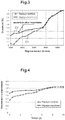
- the figure 4 which represents two curves of compressor efficiency as a function of time, respectively with and without application of the compressor fin position adjustments optimized for transient engine operation, illustrates the improvement in compressor efficiency obtained by switching on implementation of these settings in the case of transient operation. It thus appears that higher efficiencies are obtained, which are favorable for the performance and response time of the engine in transient operation, but which are also favorable for the consumption of the engine by reducing the pumping losses of the engine.
Landscapes
- Engineering & Computer Science (AREA)
- Chemical & Material Sciences (AREA)
- Combustion & Propulsion (AREA)
- Mechanical Engineering (AREA)
- General Engineering & Computer Science (AREA)
- Supercharger (AREA)
Claims (10)
- Verfahren zur Steuerung eines Turboladers für eine Brennkraftmaschine eines Kraftfahrzeugs, des Typs, welcher eine Turbine und einen Kompressor mit variabler Geometrie umfasst, wobei der Ladedruck geregelt wird, indem die Geometrie des Kompressors mit variabler Geometrie anhand eines Einstellwertes der Geometrie des Kompressors geregelt wird, wobei dieser Einstellwert aus einem ersten Kennfeld (C1) von Einstellwerten der Geometrie des Kompressors in Abhängigkeit von der Drehzahl des Motors entnommen wird, das einer optimalen Leistung des Kompressors für einen stabilisierten Betrieb des Motors entspricht,
und
ein transienter Betrieb des Motors im Anschluss an eine plötzliche Beschleunigungsanforderung des Motors detektiert wird (E1), dadurch gekennzeichnet, dass:- ab der Detektion eine Änderung der Einstellung der Geometrie des Kompressors mit variabler Geometrie anhand eines zweiten Kennfeldes (C2) von Einstellwerten der Geometrie des Kompressors in Abhängigkeit von der Drehzahl des Motors gesteuert wird (E3), das einer optimalen Leistung des Kompressors für einen transienten Betrieb des Motors entspricht, und- eine allmähliche Umschaltung von der Einstellung der Geometrie des Kompressors gemäß dem zweiten Kennfeld zur Einstellung gemäß dem ersten Kennfeld vorgenommen wird (E4), durch Detektion des zeitlichen Verlaufs des Niveaus des vom Motor erzeugten Drehmoments in Bezug auf das maximale Drehmomentniveau, das erhalten wird, wenn die Motordrehzahl stabilisiert ist. - Verfahren nach Anspruch 1, dadurch gekennzeichnet, dass allmählich vom zweiten Kennfeld zum ersten Kennfeld umgeschaltet wird, wenn das Motordrehmoment mindestens 90 % des maximalen Drehmomentniveaus beträgt, das erhalten wird, wenn die Motordrehzahl stabilisiert ist.
- Verfahren nach Anspruch 1 oder 2, dadurch gekennzeichnet, dass die Detektion (E1) des transienten Betriebs des Motors den Vergleich mit einem vordefinierten Schwellenwert des zeitlichen Verlaufs des Grades des Niedertretens des dem Motor zugeordneten Gaspedals umfasst.
- Verfahren nach Anspruch 3, dadurch gekennzeichnet, dass der transiente Betrieb detektiert wird, wenn die Ableitung des Grades des Niedertretens des Gaspedals nach der Zeit größer als der vordefinierte Schwellenwert ist.
- Verfahren nach einem der vorhergehenden Ansprüche, dadurch gekennzeichnet, dass die Einstellwerte der Geometrie des Kompressors, die im ersten und zweiten Kennfeld abgelegt sind, ermöglichen, die Ausrichtung von Schaufeln mit variabler Ausrichtung, mit denen der Kompressor ausgestattet ist, zu verstellen, wobei die Einstellwerte des zweiten Kennfeldes dafür ausgelegt sind, eine Position einer weiteren Öffnung der Schaufeln anzusteuern, als die Einstellwerte des ersten Kennfeldes in Abhängigkeit von der Motordrehzahl.
- Verfahren nach einem der vorhergehenden Ansprüche, dadurch gekennzeichnet, dass während der Durchführung der Steuerung (E3) der Geometrie des Kompressors mit variabler Geometrie gemäß dem zweiten Kennfeld (C2), wenn die Turbine des Turboladers eine Turbine mit variabler Geometrie ist, die mit Schaufeln mit variabler Ausrichtung ausgestattet ist, die Ausrichtung der Schaufeln der Turbine in eine Position des Schließens der Schaufeln eingestellt wird (E5) und ein Sollwert der Anreicherung für den Motor erstellt wird, welcher der für den Motor zulässigen maximalen Anreicherung entspricht, solange der im Ansaugkrümmer des Motors gemessene Druck niedriger als ein Solldruck ist, der für den erforderlichen Ladedruck repräsentativ ist.
- Verfahren nach einem der Ansprüche 1 bis 5, dadurch gekennzeichnet, dass während der Durchführung der Steuerung (E3) der Geometrie des Kompressors mit variabler Geometrie gemäß dem zweiten Kennfeld (C2), wenn die Turbine des Turboladers eine Turbine mit fester Geometrie ist, ein Wastegate, das zwischen einem Abgasauslassventil am Ausgang des Motors und dem Einlass der Turbine angeordnet ist, in eine Schließposition gestellt wird, um die gesamten Abgase durch die Turbine strömen zu lassen, und ein Sollwert der Anreicherung für den Motor erstellt wird, welcher der für den Motor zulässigen maximalen Anreicherung entspricht, solange der im Ansaugkrümmer des Motors gemessene Druck niedriger als ein Solldruck ist, der für den erforderlichen Ladedruck repräsentativ ist.
- Verfahren nach einem der Ansprüche 6 oder 7, dadurch gekennzeichnet, dass während der Durchführung der allmählichen Umschaltung (E4) von der Einstellung der Geometrie des Kompressors gemäß dem zweiten Kennfeld zur Einstellung gemäß dem ersten Kennfeld der Ladedruck im Ansaugkrümmer so geregelt wird (E6), dass er dem Ladedruck nahekommt, der erforderlich ist, um das maximale Drehmoment zu erreichen, wenn die Motordrehzahl stabilisiert ist, indem die Geometrie der Turbine geändert wird oder indem das Wastegate angesteuert wird.
- Brennkraftmaschine mit Aufladung, welche einen Turbolader des Typs umfasst, welcher eine Turbine und einen Kompressor mit variabler Geometrie aufweist, wobei ein elektronisches Steuergerät des Motors auf eine Steuerung der Geometrie des Kompressors einwirkt, dadurch gekennzeichnet, dass das Steuergerät dafür ausgelegt ist, alle Schritte des Verfahrens nach einem der vorhergehenden Ansprüche auszuführen.
- Kraftfahrzeug, dadurch gekennzeichnet, dass es eine Brennkraftmaschine nach Anspruch 9 umfasst.
Applications Claiming Priority (2)
| Application Number | Priority Date | Filing Date | Title |
|---|---|---|---|
| FR1661932A FR3059713B1 (fr) | 2016-12-05 | 2016-12-05 | Procede de commande d'un turbocompresseur de suralimentation pour moteur a combustion interne |
| PCT/FR2017/053387 WO2018104646A1 (fr) | 2016-12-05 | 2017-12-05 | Procédé de commande d'un turbocompresseur de suralimentation pour moteur à combustion interne |
Publications (2)
| Publication Number | Publication Date |
|---|---|
| EP3548728A1 EP3548728A1 (de) | 2019-10-09 |
| EP3548728B1 true EP3548728B1 (de) | 2020-10-07 |
Family
ID=57909731
Family Applications (1)
| Application Number | Title | Priority Date | Filing Date |
|---|---|---|---|
| EP17816988.4A Active EP3548728B1 (de) | 2016-12-05 | 2017-12-05 | Verfahren zur steuerung eines turbokompressors zur aufladung für eine brennkraftmaschine |
Country Status (5)
| Country | Link |
|---|---|
| EP (1) | EP3548728B1 (de) |
| CN (1) | CN110168211A (de) |
| FR (1) | FR3059713B1 (de) |
| RU (1) | RU2019120912A (de) |
| WO (1) | WO2018104646A1 (de) |
Families Citing this family (2)
| Publication number | Priority date | Publication date | Assignee | Title |
|---|---|---|---|---|
| FR3102216B1 (fr) * | 2019-10-17 | 2022-07-15 | Renault Sas | Procede de controle de la suralimentation en air d’un moteur a combustion |
| GB2591776B (en) * | 2020-02-06 | 2023-02-01 | Caterpillar Inc | Improvements in turbocharger efficiency |
Family Cites Families (11)
| Publication number | Priority date | Publication date | Assignee | Title |
|---|---|---|---|---|
| US4970864A (en) * | 1987-12-29 | 1990-11-20 | Honda Giken Kogyo K.K. | Supercharging pressure control method for internal combustion engines |
| US6000221A (en) * | 1997-11-04 | 1999-12-14 | Detroit Diesel Corporation | System for controlling a variable geometry turbocharger |
| DE19844214C1 (de) * | 1998-09-26 | 1999-05-27 | Daimler Chrysler Ag | Verfahren zur Regelung oder Steuerung einer aufgeladenen Brennkraftmaschine |
| JP3698673B2 (ja) * | 2001-12-25 | 2005-09-21 | 日野自動車株式会社 | ターボ過給機付エンジンの過給圧制御装置 |
| JP2003193852A (ja) * | 2001-12-26 | 2003-07-09 | Hino Motors Ltd | ターボ過給機付エンジンの吸気圧制御装置 |
| CN1162611C (zh) * | 2002-04-19 | 2004-08-18 | 清华大学 | 一种车用发动机可变喷嘴涡轮增压控制方法及系统 |
| US7124582B2 (en) * | 2004-07-26 | 2006-10-24 | International Engine Intellectual Property Company, Llc | Method and apparatus for determining turbocharger boost |
| JP2006242029A (ja) * | 2005-03-01 | 2006-09-14 | Denso Corp | 過給アシスト制御システム |
| FR2915237B1 (fr) * | 2007-04-20 | 2012-11-09 | Renault Sas | Systeme et procede de commande d'un turbocompresseur de suralimentation pour moteur a combustion interne |
| CN101328831A (zh) * | 2008-08-04 | 2008-12-24 | 清华大学 | 柴油机变海拔自适应增压控制方法及系统 |
| CN101387236B (zh) * | 2008-11-03 | 2010-06-23 | 北京汽车研究总院有限公司 | 一种可变喷嘴涡轮增压控制方法及系统 |
-
2016
- 2016-12-05 FR FR1661932A patent/FR3059713B1/fr not_active Expired - Fee Related
-
2017
- 2017-12-05 EP EP17816988.4A patent/EP3548728B1/de active Active
- 2017-12-05 RU RU2019120912A patent/RU2019120912A/ru not_active Application Discontinuation
- 2017-12-05 CN CN201780082463.9A patent/CN110168211A/zh active Pending
- 2017-12-05 WO PCT/FR2017/053387 patent/WO2018104646A1/fr not_active Ceased
Also Published As
| Publication number | Publication date |
|---|---|
| CN110168211A (zh) | 2019-08-23 |
| EP3548728A1 (de) | 2019-10-09 |
| RU2019120912A3 (de) | 2021-01-11 |
| WO2018104646A1 (fr) | 2018-06-14 |
| FR3059713A1 (fr) | 2018-06-08 |
| FR3059713B1 (fr) | 2018-11-16 |
| RU2019120912A (ru) | 2021-01-11 |
Similar Documents
| Publication | Publication Date | Title |
|---|---|---|
| CN101302942B (zh) | 控制可变几何涡轮增压器的最小流量的系统和方法 | |
| JP5786970B2 (ja) | 内燃機関の制御装置 | |
| JP2014015846A (ja) | 過給機付内燃機関の制御装置、過給機付内燃機関を搭載した車両 | |
| JP2010048225A (ja) | 内燃機関の過給システム | |
| WO2018104646A1 (fr) | Procédé de commande d'un turbocompresseur de suralimentation pour moteur à combustion interne | |
| JP2014196678A (ja) | 過給機付き内燃機関の制御装置 | |
| JP6462504B2 (ja) | 過給機付き内燃機関の制御装置およびその制御方法 | |
| FR3058472B1 (fr) | Procede de commande d'un moteur thermique suralimente equipe d'un mecanisme de deconnexion de cylindres. | |
| EP3155249B1 (de) | Verfahren zur ventilsteuerung zur rückführung von abgasen | |
| JP2007247540A (ja) | Egrシステムの制御方法及びegrシステム | |
| EP4229289B1 (de) | Verfahren zur bestimmung eines maximalen positionssollwerts für eine turboladerturbine | |
| JP4179263B2 (ja) | 過給機付内燃機関 | |
| FR2914949A1 (fr) | Moteur a combustion interne, appareil de commande du moteur et procede de gestion d'un moteur a combustion interne a turbocompresseur | |
| US11268436B2 (en) | Method and vehicle system using such method | |
| EP2452060A1 (de) | Verfahren zur steuerung des in einen motor injizierten luftstroms, anordnung mit einem computer zur umsetzung des verfahrens und fahrzeug mit der anordnung | |
| JP2004239112A (ja) | エンジンの吸気制御方法 | |
| JP7753945B2 (ja) | 内燃機関の最大充填効率推定方法および装置 | |
| EP3652426B1 (de) | Verfahren zur steuerung eines aufladeverbrennungsmotors | |
| FR2907848A1 (fr) | Moteur a combustion interne comportant au moins un turbocompresseur a fonctionnement a bas regime ameliore | |
| JP6154232B2 (ja) | 過給機付きエンジンの制御装置 | |
| FR3144846A1 (fr) | Procédé d'optimisation de la performance stabilisée en conditions extrêmes d'un moteur à combustion interne suralimenté | |
| EP3808959A1 (de) | Verfahren zur kontrolle der luftaufladung eines verbrennungsmotors | |
| WO2025104502A1 (en) | Method for increasing the torque of a heat engine, corresponding heat engine, and motor vehicle comprising such a heat engine | |
| FR3059712A1 (fr) | Procede de commande d'un moteur a combustion interne suralimente par un turbocompresseur couple a un compresseur additionnel ou a une assistance electrique | |
| FR2908475A1 (fr) | Moteur a combustion interne adapte a reduire le temps de transition pour le passage d'un fonctionnement du moteur a faible charge a un fonctionnement a pleine charge |
Legal Events
| Date | Code | Title | Description |
|---|---|---|---|
| STAA | Information on the status of an ep patent application or granted ep patent |
Free format text: STATUS: UNKNOWN |
|
| STAA | Information on the status of an ep patent application or granted ep patent |
Free format text: STATUS: THE INTERNATIONAL PUBLICATION HAS BEEN MADE |
|
| PUAI | Public reference made under article 153(3) epc to a published international application that has entered the european phase |
Free format text: ORIGINAL CODE: 0009012 |
|
| STAA | Information on the status of an ep patent application or granted ep patent |
Free format text: STATUS: REQUEST FOR EXAMINATION WAS MADE |
|
| 17P | Request for examination filed |
Effective date: 20190606 |
|
| AK | Designated contracting states |
Kind code of ref document: A1 Designated state(s): AL AT BE BG CH CY CZ DE DK EE ES FI FR GB GR HR HU IE IS IT LI LT LU LV MC MK MT NL NO PL PT RO RS SE SI SK SM TR |
|
| AX | Request for extension of the european patent |
Extension state: BA ME |
|
| DAV | Request for validation of the european patent (deleted) | ||
| DAX | Request for extension of the european patent (deleted) | ||
| RIC1 | Information provided on ipc code assigned before grant |
Ipc: F02B 37/24 20060101ALI20200309BHEP Ipc: F02D 33/02 20060101ALI20200309BHEP Ipc: F02B 37/18 20060101ALI20200309BHEP Ipc: F02B 39/00 20060101ALI20200309BHEP Ipc: F02D 23/02 20060101AFI20200309BHEP Ipc: F02D 41/10 20060101ALI20200309BHEP Ipc: F02D 41/24 20060101ALI20200309BHEP Ipc: F02D 41/04 20060101ALI20200309BHEP |
|
| GRAP | Despatch of communication of intention to grant a patent |
Free format text: ORIGINAL CODE: EPIDOSNIGR1 |
|
| STAA | Information on the status of an ep patent application or granted ep patent |
Free format text: STATUS: GRANT OF PATENT IS INTENDED |
|
| INTG | Intention to grant announced |
Effective date: 20200507 |
|
| GRAS | Grant fee paid |
Free format text: ORIGINAL CODE: EPIDOSNIGR3 |
|
| GRAA | (expected) grant |
Free format text: ORIGINAL CODE: 0009210 |
|
| STAA | Information on the status of an ep patent application or granted ep patent |
Free format text: STATUS: THE PATENT HAS BEEN GRANTED |
|
| AK | Designated contracting states |
Kind code of ref document: B1 Designated state(s): AL AT BE BG CH CY CZ DE DK EE ES FI FR GB GR HR HU IE IS IT LI LT LU LV MC MK MT NL NO PL PT RO RS SE SI SK SM TR |
|
| REG | Reference to a national code |
Ref country code: GB Ref legal event code: FG4D Free format text: NOT ENGLISH |
|
| REG | Reference to a national code |
Ref country code: AT Ref legal event code: REF Ref document number: 1321394 Country of ref document: AT Kind code of ref document: T Effective date: 20201015 Ref country code: CH Ref legal event code: EP |
|
| REG | Reference to a national code |
Ref country code: IE Ref legal event code: FG4D Free format text: LANGUAGE OF EP DOCUMENT: FRENCH |
|
| REG | Reference to a national code |
Ref country code: DE Ref legal event code: R096 Ref document number: 602017025183 Country of ref document: DE |
|
| REG | Reference to a national code |
Ref country code: NL Ref legal event code: MP Effective date: 20201007 |
|
| REG | Reference to a national code |
Ref country code: AT Ref legal event code: MK05 Ref document number: 1321394 Country of ref document: AT Kind code of ref document: T Effective date: 20201007 |
|
| PG25 | Lapsed in a contracting state [announced via postgrant information from national office to epo] |
Ref country code: GR Free format text: LAPSE BECAUSE OF FAILURE TO SUBMIT A TRANSLATION OF THE DESCRIPTION OR TO PAY THE FEE WITHIN THE PRESCRIBED TIME-LIMIT Effective date: 20210108 Ref country code: NO Free format text: LAPSE BECAUSE OF FAILURE TO SUBMIT A TRANSLATION OF THE DESCRIPTION OR TO PAY THE FEE WITHIN THE PRESCRIBED TIME-LIMIT Effective date: 20210107 Ref country code: RS Free format text: LAPSE BECAUSE OF FAILURE TO SUBMIT A TRANSLATION OF THE DESCRIPTION OR TO PAY THE FEE WITHIN THE PRESCRIBED TIME-LIMIT Effective date: 20201007 Ref country code: PT Free format text: LAPSE BECAUSE OF FAILURE TO SUBMIT A TRANSLATION OF THE DESCRIPTION OR TO PAY THE FEE WITHIN THE PRESCRIBED TIME-LIMIT Effective date: 20210208 Ref country code: FI Free format text: LAPSE BECAUSE OF FAILURE TO SUBMIT A TRANSLATION OF THE DESCRIPTION OR TO PAY THE FEE WITHIN THE PRESCRIBED TIME-LIMIT Effective date: 20201007 |
|
| REG | Reference to a national code |
Ref country code: LT Ref legal event code: MG4D |
|
| PG25 | Lapsed in a contracting state [announced via postgrant information from national office to epo] |
Ref country code: PL Free format text: LAPSE BECAUSE OF FAILURE TO SUBMIT A TRANSLATION OF THE DESCRIPTION OR TO PAY THE FEE WITHIN THE PRESCRIBED TIME-LIMIT Effective date: 20201007 Ref country code: LV Free format text: LAPSE BECAUSE OF FAILURE TO SUBMIT A TRANSLATION OF THE DESCRIPTION OR TO PAY THE FEE WITHIN THE PRESCRIBED TIME-LIMIT Effective date: 20201007 Ref country code: IS Free format text: LAPSE BECAUSE OF FAILURE TO SUBMIT A TRANSLATION OF THE DESCRIPTION OR TO PAY THE FEE WITHIN THE PRESCRIBED TIME-LIMIT Effective date: 20210207 Ref country code: SE Free format text: LAPSE BECAUSE OF FAILURE TO SUBMIT A TRANSLATION OF THE DESCRIPTION OR TO PAY THE FEE WITHIN THE PRESCRIBED TIME-LIMIT Effective date: 20201007 Ref country code: BG Free format text: LAPSE BECAUSE OF FAILURE TO SUBMIT A TRANSLATION OF THE DESCRIPTION OR TO PAY THE FEE WITHIN THE PRESCRIBED TIME-LIMIT Effective date: 20210107 Ref country code: ES Free format text: LAPSE BECAUSE OF FAILURE TO SUBMIT A TRANSLATION OF THE DESCRIPTION OR TO PAY THE FEE WITHIN THE PRESCRIBED TIME-LIMIT Effective date: 20201007 Ref country code: AT Free format text: LAPSE BECAUSE OF FAILURE TO SUBMIT A TRANSLATION OF THE DESCRIPTION OR TO PAY THE FEE WITHIN THE PRESCRIBED TIME-LIMIT Effective date: 20201007 |
|
| PG25 | Lapsed in a contracting state [announced via postgrant information from national office to epo] |
Ref country code: NL Free format text: LAPSE BECAUSE OF FAILURE TO SUBMIT A TRANSLATION OF THE DESCRIPTION OR TO PAY THE FEE WITHIN THE PRESCRIBED TIME-LIMIT Effective date: 20201007 Ref country code: HR Free format text: LAPSE BECAUSE OF FAILURE TO SUBMIT A TRANSLATION OF THE DESCRIPTION OR TO PAY THE FEE WITHIN THE PRESCRIBED TIME-LIMIT Effective date: 20201007 |
|
| REG | Reference to a national code |
Ref country code: DE Ref legal event code: R097 Ref document number: 602017025183 Country of ref document: DE |
|
| PG25 | Lapsed in a contracting state [announced via postgrant information from national office to epo] |
Ref country code: SM Free format text: LAPSE BECAUSE OF FAILURE TO SUBMIT A TRANSLATION OF THE DESCRIPTION OR TO PAY THE FEE WITHIN THE PRESCRIBED TIME-LIMIT Effective date: 20201007 Ref country code: LT Free format text: LAPSE BECAUSE OF FAILURE TO SUBMIT A TRANSLATION OF THE DESCRIPTION OR TO PAY THE FEE WITHIN THE PRESCRIBED TIME-LIMIT Effective date: 20201007 Ref country code: EE Free format text: LAPSE BECAUSE OF FAILURE TO SUBMIT A TRANSLATION OF THE DESCRIPTION OR TO PAY THE FEE WITHIN THE PRESCRIBED TIME-LIMIT Effective date: 20201007 Ref country code: CZ Free format text: LAPSE BECAUSE OF FAILURE TO SUBMIT A TRANSLATION OF THE DESCRIPTION OR TO PAY THE FEE WITHIN THE PRESCRIBED TIME-LIMIT Effective date: 20201007 Ref country code: SK Free format text: LAPSE BECAUSE OF FAILURE TO SUBMIT A TRANSLATION OF THE DESCRIPTION OR TO PAY THE FEE WITHIN THE PRESCRIBED TIME-LIMIT Effective date: 20201007 Ref country code: RO Free format text: LAPSE BECAUSE OF FAILURE TO SUBMIT A TRANSLATION OF THE DESCRIPTION OR TO PAY THE FEE WITHIN THE PRESCRIBED TIME-LIMIT Effective date: 20201007 |
|
| REG | Reference to a national code |
Ref country code: CH Ref legal event code: PL |
|
| PLBE | No opposition filed within time limit |
Free format text: ORIGINAL CODE: 0009261 |
|
| STAA | Information on the status of an ep patent application or granted ep patent |
Free format text: STATUS: NO OPPOSITION FILED WITHIN TIME LIMIT |
|
| PG25 | Lapsed in a contracting state [announced via postgrant information from national office to epo] |
Ref country code: MC Free format text: LAPSE BECAUSE OF FAILURE TO SUBMIT A TRANSLATION OF THE DESCRIPTION OR TO PAY THE FEE WITHIN THE PRESCRIBED TIME-LIMIT Effective date: 20201007 Ref country code: DK Free format text: LAPSE BECAUSE OF FAILURE TO SUBMIT A TRANSLATION OF THE DESCRIPTION OR TO PAY THE FEE WITHIN THE PRESCRIBED TIME-LIMIT Effective date: 20201007 |
|
| REG | Reference to a national code |
Ref country code: BE Ref legal event code: MM Effective date: 20201231 |
|
| 26N | No opposition filed |
Effective date: 20210708 |
|
| PG25 | Lapsed in a contracting state [announced via postgrant information from national office to epo] |
Ref country code: AL Free format text: LAPSE BECAUSE OF FAILURE TO SUBMIT A TRANSLATION OF THE DESCRIPTION OR TO PAY THE FEE WITHIN THE PRESCRIBED TIME-LIMIT Effective date: 20201007 Ref country code: LU Free format text: LAPSE BECAUSE OF NON-PAYMENT OF DUE FEES Effective date: 20201205 Ref country code: IT Free format text: LAPSE BECAUSE OF FAILURE TO SUBMIT A TRANSLATION OF THE DESCRIPTION OR TO PAY THE FEE WITHIN THE PRESCRIBED TIME-LIMIT Effective date: 20201007 Ref country code: IE Free format text: LAPSE BECAUSE OF NON-PAYMENT OF DUE FEES Effective date: 20201205 |
|
| PG25 | Lapsed in a contracting state [announced via postgrant information from national office to epo] |
Ref country code: LI Free format text: LAPSE BECAUSE OF NON-PAYMENT OF DUE FEES Effective date: 20201231 Ref country code: CH Free format text: LAPSE BECAUSE OF NON-PAYMENT OF DUE FEES Effective date: 20201231 Ref country code: SI Free format text: LAPSE BECAUSE OF FAILURE TO SUBMIT A TRANSLATION OF THE DESCRIPTION OR TO PAY THE FEE WITHIN THE PRESCRIBED TIME-LIMIT Effective date: 20201007 |
|
| PG25 | Lapsed in a contracting state [announced via postgrant information from national office to epo] |
Ref country code: IS Free format text: LAPSE BECAUSE OF FAILURE TO SUBMIT A TRANSLATION OF THE DESCRIPTION OR TO PAY THE FEE WITHIN THE PRESCRIBED TIME-LIMIT Effective date: 20210207 Ref country code: TR Free format text: LAPSE BECAUSE OF FAILURE TO SUBMIT A TRANSLATION OF THE DESCRIPTION OR TO PAY THE FEE WITHIN THE PRESCRIBED TIME-LIMIT Effective date: 20201007 Ref country code: MT Free format text: LAPSE BECAUSE OF FAILURE TO SUBMIT A TRANSLATION OF THE DESCRIPTION OR TO PAY THE FEE WITHIN THE PRESCRIBED TIME-LIMIT Effective date: 20201007 Ref country code: CY Free format text: LAPSE BECAUSE OF FAILURE TO SUBMIT A TRANSLATION OF THE DESCRIPTION OR TO PAY THE FEE WITHIN THE PRESCRIBED TIME-LIMIT Effective date: 20201007 |
|
| PG25 | Lapsed in a contracting state [announced via postgrant information from national office to epo] |
Ref country code: MK Free format text: LAPSE BECAUSE OF FAILURE TO SUBMIT A TRANSLATION OF THE DESCRIPTION OR TO PAY THE FEE WITHIN THE PRESCRIBED TIME-LIMIT Effective date: 20201007 |
|
| PG25 | Lapsed in a contracting state [announced via postgrant information from national office to epo] |
Ref country code: BE Free format text: LAPSE BECAUSE OF NON-PAYMENT OF DUE FEES Effective date: 20201231 |
|
| P01 | Opt-out of the competence of the unified patent court (upc) registered |
Effective date: 20230608 |
|
| REG | Reference to a national code |
Ref country code: GB Ref legal event code: 732E Free format text: REGISTERED BETWEEN 20231228 AND 20240103 |
|
| REG | Reference to a national code |
Ref country code: DE Ref legal event code: R081 Ref document number: 602017025183 Country of ref document: DE Owner name: AMPERE S.A.S., FR Free format text: FORMER OWNER: RENAULT S.A.S., BOULOGNE-BILLANCOURT, FR |
|
| PGFP | Annual fee paid to national office [announced via postgrant information from national office to epo] |
Ref country code: DE Payment date: 20251211 Year of fee payment: 9 |
|
| PGFP | Annual fee paid to national office [announced via postgrant information from national office to epo] |
Ref country code: GB Payment date: 20251219 Year of fee payment: 9 |
|
| PGFP | Annual fee paid to national office [announced via postgrant information from national office to epo] |
Ref country code: FR Payment date: 20251229 Year of fee payment: 9 |