EP3548986B1 - Kühlung mithilfe verstellbarer thermischer kopplung - Google Patents
Kühlung mithilfe verstellbarer thermischer kopplung Download PDFInfo
- Publication number
- EP3548986B1 EP3548986B1 EP17876717.4A EP17876717A EP3548986B1 EP 3548986 B1 EP3548986 B1 EP 3548986B1 EP 17876717 A EP17876717 A EP 17876717A EP 3548986 B1 EP3548986 B1 EP 3548986B1
- Authority
- EP
- European Patent Office
- Prior art keywords
- cold plate
- thermal interface
- thermally
- interface plane
- coupled
- Prior art date
- Legal status (The legal status is an assumption and is not a legal conclusion. Google has not performed a legal analysis and makes no representation as to the accuracy of the status listed.)
- Active
Links
Images


Classifications
-
- G—PHYSICS
- G06—COMPUTING OR CALCULATING; COUNTING
- G06F—ELECTRIC DIGITAL DATA PROCESSING
- G06F1/00—Details not covered by groups G06F3/00 - G06F13/00 and G06F21/00
- G06F1/16—Constructional details or arrangements
- G06F1/20—Cooling means
-
- F—MECHANICAL ENGINEERING; LIGHTING; HEATING; WEAPONS; BLASTING
- F28—HEAT EXCHANGE IN GENERAL
- F28F—DETAILS OF HEAT-EXCHANGE AND HEAT-TRANSFER APPARATUS, OF GENERAL APPLICATION
- F28F9/00—Casings; Header boxes; Auxiliary supports for elements; Auxiliary members within casings
- F28F9/26—Arrangements for connecting different sections of heat-exchange elements, e.g. of radiators
- F28F9/262—Arrangements for connecting different sections of heat-exchange elements, e.g. of radiators for radiators
- F28F9/266—Arrangements for connecting different sections of heat-exchange elements, e.g. of radiators for radiators by screw-type connections
-
- H—ELECTRICITY
- H05—ELECTRIC TECHNIQUES NOT OTHERWISE PROVIDED FOR
- H05K—PRINTED CIRCUITS; CASINGS OR CONSTRUCTIONAL DETAILS OF ELECTRIC APPARATUS; MANUFACTURE OF ASSEMBLAGES OF ELECTRICAL COMPONENTS
- H05K1/00—Printed circuits
- H05K1/02—Details
- H05K1/0201—Thermal arrangements, e.g. for cooling, heating or preventing overheating
- H05K1/0203—Cooling of mounted components
-
- H—ELECTRICITY
- H05—ELECTRIC TECHNIQUES NOT OTHERWISE PROVIDED FOR
- H05K—PRINTED CIRCUITS; CASINGS OR CONSTRUCTIONAL DETAILS OF ELECTRIC APPARATUS; MANUFACTURE OF ASSEMBLAGES OF ELECTRICAL COMPONENTS
- H05K1/00—Printed circuits
- H05K1/18—Printed circuits structurally associated with non-printed electric components
-
- H—ELECTRICITY
- H05—ELECTRIC TECHNIQUES NOT OTHERWISE PROVIDED FOR
- H05K—PRINTED CIRCUITS; CASINGS OR CONSTRUCTIONAL DETAILS OF ELECTRIC APPARATUS; MANUFACTURE OF ASSEMBLAGES OF ELECTRICAL COMPONENTS
- H05K7/00—Constructional details common to different types of electric apparatus
- H05K7/20—Modifications to facilitate cooling, ventilating, or heating
- H05K7/20218—Modifications to facilitate cooling, ventilating, or heating using a liquid coolant without phase change in electronic enclosures
- H05K7/20254—Cold plates transferring heat from heat source to coolant
-
- H—ELECTRICITY
- H05—ELECTRIC TECHNIQUES NOT OTHERWISE PROVIDED FOR
- H05K—PRINTED CIRCUITS; CASINGS OR CONSTRUCTIONAL DETAILS OF ELECTRIC APPARATUS; MANUFACTURE OF ASSEMBLAGES OF ELECTRICAL COMPONENTS
- H05K7/00—Constructional details common to different types of electric apparatus
- H05K7/20—Modifications to facilitate cooling, ventilating, or heating
- H05K7/2039—Modifications to facilitate cooling, ventilating, or heating characterised by the heat transfer by conduction from the heat generating element to a dissipating body
- H05K7/20436—Inner thermal coupling elements in heat dissipating housings, e.g. protrusions or depressions integrally formed in the housing
- H05K7/2049—Pressing means used to urge contact, e.g. springs
-
- H—ELECTRICITY
- H05—ELECTRIC TECHNIQUES NOT OTHERWISE PROVIDED FOR
- H05K—PRINTED CIRCUITS; CASINGS OR CONSTRUCTIONAL DETAILS OF ELECTRIC APPARATUS; MANUFACTURE OF ASSEMBLAGES OF ELECTRICAL COMPONENTS
- H05K7/00—Constructional details common to different types of electric apparatus
- H05K7/20—Modifications to facilitate cooling, ventilating, or heating
- H05K7/2039—Modifications to facilitate cooling, ventilating, or heating characterised by the heat transfer by conduction from the heat generating element to a dissipating body
- H05K7/20509—Multiple-component heat spreaders; Multi-component heat-conducting support plates; Multi-component non-closed heat-conducting structures
-
- H—ELECTRICITY
- H10—SEMICONDUCTOR DEVICES; ELECTRIC SOLID-STATE DEVICES NOT OTHERWISE PROVIDED FOR
- H10W—GENERIC PACKAGES, INTERCONNECTIONS, CONNECTORS OR OTHER CONSTRUCTIONAL DETAILS OF DEVICES COVERED BY CLASS H10
- H10W40/00—Arrangements for thermal protection or thermal control
- H10W40/40—Arrangements for thermal protection or thermal control involving heat exchange by flowing fluids
- H10W40/47—Arrangements for thermal protection or thermal control involving heat exchange by flowing fluids by flowing liquids, e.g. forced water cooling
-
- H—ELECTRICITY
- H10—SEMICONDUCTOR DEVICES; ELECTRIC SOLID-STATE DEVICES NOT OTHERWISE PROVIDED FOR
- H10W—GENERIC PACKAGES, INTERCONNECTIONS, CONNECTORS OR OTHER CONSTRUCTIONAL DETAILS OF DEVICES COVERED BY CLASS H10
- H10W40/00—Arrangements for thermal protection or thermal control
- H10W40/60—Securing means for detachable heating or cooling arrangements, e.g. clamps
-
- F—MECHANICAL ENGINEERING; LIGHTING; HEATING; WEAPONS; BLASTING
- F28—HEAT EXCHANGE IN GENERAL
- F28F—DETAILS OF HEAT-EXCHANGE AND HEAT-TRANSFER APPARATUS, OF GENERAL APPLICATION
- F28F2280/00—Mounting arrangements; Arrangements for facilitating assembling or disassembling of heat exchanger parts
- F28F2280/10—Movable elements, e.g. being pivotable
-
- G—PHYSICS
- G06—COMPUTING OR CALCULATING; COUNTING
- G06F—ELECTRIC DIGITAL DATA PROCESSING
- G06F1/00—Details not covered by groups G06F3/00 - G06F13/00 and G06F21/00
- G06F1/16—Constructional details or arrangements
- G06F1/18—Packaging or power distribution
- G06F1/183—Internal mounting support structures, e.g. for supporting printed circuit boards
- G06F1/188—Mounting of power supply units
-
- H—ELECTRICITY
- H10—SEMICONDUCTOR DEVICES; ELECTRIC SOLID-STATE DEVICES NOT OTHERWISE PROVIDED FOR
- H10W—GENERIC PACKAGES, INTERCONNECTIONS, CONNECTORS OR OTHER CONSTRUCTIONAL DETAILS OF DEVICES COVERED BY CLASS H10
- H10W40/00—Arrangements for thermal protection or thermal control
- H10W40/10—Arrangements for heating
-
- H—ELECTRICITY
- H10—SEMICONDUCTOR DEVICES; ELECTRIC SOLID-STATE DEVICES NOT OTHERWISE PROVIDED FOR
- H10W—GENERIC PACKAGES, INTERCONNECTIONS, CONNECTORS OR OTHER CONSTRUCTIONAL DETAILS OF DEVICES COVERED BY CLASS H10
- H10W40/00—Arrangements for thermal protection or thermal control
- H10W40/20—Arrangements for cooling
- H10W40/231—Arrangements for cooling characterised by their places of attachment or cooling paths
- H10W40/237—Arrangements for cooling characterised by their places of attachment or cooling paths attached to additional arrangements for cooling
Definitions
- Embodiments of the present disclosure generally relate to the field of computing systems. More specifically, embodiments of the present disclosure relate to cooling electronic and/or optical components in a computing system.
- CPU central processing unit
- TDP thermal design power
- Legacy air cooled reference platforms are typically built per American Society of Heating, Refrigerating and Air-Conditioning Engineers (ASHRAE) Class A2.
- HVAC Heating, Refrigerating and Air-Conditioning Engineers
- liquid-enhanced cooling solutions are typically used where components are cooled by liquid cold plates.
- gap filler thermal interface material in thermal contact with a cold plate and one or more heat-generating components, such as a central processing unit (CPU), that on a printed circuit board (PCB).
- CPU central processing unit
- PCB printed circuit board
- a first heat sink is engaged to and is in thermal communication with the first integrated circuit package
- a second heat sink is engaged to and is in thermal communication with the second integrated circuit package, wherein each of the first and second heat sinks are positioned over the first and second integrated circuit packages on a single side of the circuit board.
- the first heat sink may include-an opening extending therethrough and exposing the second integrated circuit package.
- the second heat sink may extend through the opening and engage the second integrated circuit package.
- Document US 2016/0284624 A1 describes a heat sink structure, which includes: a first heat sink; a second heat sink having a protrusion in a lower part of a side surface thereof; a thermal conductivity substance sandwiched between a side surface of the first heat sink and a side surface of the second heat sink; and a flexible cushioning material sandwiched between the bottom surface of the first heat sink and the top surface of the aforementioned protrusion.
- Document US 2016/0079140 A1 relates to a package for a multi-chip module, which includes a top cold plate and a bottom plate whose perimeters are in thermal communication so the plates together completely encase the module except for a connector passing through the bottom plate.
- the cold plate has copper tubing pressed into a groove formed in a serpentine pattern.
- the perimeter of the cold plate has thermal conduction fins which mate with thermal conduction slots in the perimeter of the bottom plate.
- Thermal interface material is disposed in gaps between the plates and chips on the module, the gaps having dimensions controlled by support ribs of plates which abut the module substrate.
- the cold plate is used on the hottest side of the module, e.g., the side having computationally-intensive chips such as ASICs. A densely packed array of these packages can be used in a central electronic complex drawer with a shared coolant circulation system.
- Embodiments described herein may include apparatus, system and/or processes to provide an adjustable thermal coupling between cold plate coupled to a first heat source and a liquid-cooled cold plate cooling a second heat source.
- the first heat source may be a liquid-cooled cold plate for a central processing unit (CPU).
- the second heat source may be an adaptable voltage regulator (VR) cold plate.
- VR adaptable voltage regulator
- the adjustable thermal coupling may allow Z-height flexibility for a VR cold plate with respect to a CPU liquid-cooled cold plate.
- Embodiments may have advantages in readily accommodating cooling VR components having different heights on a PCB by adjustably attaching a VR cold plate to an existing liquid-cooled cold plate of a CPU, also mounted on the PCB, in proximity to the VR. With these configurations, cold plates attached to different VR designs with different heights may be thermally coupled with liquid-cooled cold plates of the CPU by first adjusting for the different VR heights and then securing the adjustable thermal coupling. This process may reduce the strain on the PCB while providing cooling for both VR's and CPUs.
- a Z-height may represent a height distance perpendicular to the PCB plane.
- providing cooling using adjustable thermal coupling may provide several advantages.
- One advantage may relate to cost.
- the cost associated with liquid cooling may be high compared to existing air cooling approaches.
- Current VR liquid cooling approaches use a separate liquid loop or a large machined cooling block to cool the VR.
- Embodiments may leverage the cost invested into the CPU liquid-cooled cold plate by tying the VR cold plate thermally and mechanically to the CPU cold plate. Thus, no additional liquid lines may be needed for the VR.
- the VR cold plate may be pure copper and may rely on conduction to transfer heat from the VR to the CPU liquid-cooled cold plate.
- a VR cold plate may be able to use a universal interface with a CPU liquid-cooled cold plate. This may readily allow for different VR designs for PCB to have custom VR cold plates ready for manufacturing. The customer may use various VR cold plate designs while still having them interface with the same CPU cold plate.
- An adjustable VR cold plate Z-height setting may allow the user to accommodate different VR suppliers that may have different Z-height VR components for the same motherboard.
- adjustable thermal coupling may allow the cold plate to mechanically and thermally couple with the VR to minimize the thermal interface material (TIM) thickness between the VR and the VR cold plate. This may lead to improved thermal performance.
- TIM thermal interface material
- phrase “A and/or B” means (A), (B), or (A and B).
- phrase “A, B, and/or C” means (A), (B), (C), (A and B), (A and C), (B and C), or (A, B, and C).
- Coupled may mean one or more of the following. “Coupled” may mean that two or more elements are in direct physical, thermal or electrical contact. However, “coupled” may also mean that two or more elements indirectly contact each other, but yet still cooperate or interact with each other, and may mean that one or more other elements are coupled or connected between the elements that are said to be coupled with each other.
- “coupled” may mean two or more elements or devices are coupled by electrical connections on a printed circuit board such as a motherboard, for example.
- “coupled” may mean two or more elements/devices cooperate and/or interact.
- a computing apparatus may include two or more computing devices “coupled” on a motherboard or by one or more network linkages.
- FIG. 1 illustrates an example implementation of cooling using adjustable thermal coupling, in accordance with various embodiments.
- Diagram 100 shows a liquid-cooled cold plate 102 cooling a CPU (not shown) which may be thermally connected to the liquid-cooled cold plate 102. Liquid to cool the liquid-cooled cold plate may flow from an inlet 102a through the cold plate 102 to an outlet 102b.
- a VR cold plate 106 may be cooling a VR (not shown) underneath the VR cold plate 106.
- CPU and the VR may be attached to a PCB 108.
- the liquid-cooled cold plate 102 may be thermally coupled to the VR cold plate 106 via a thermal interface plane 104.
- the thermal interface plane 104 may provide adjustable thermal coupling based upon its connection to the VR cold plate 106 and the liquid-cooled cold plate 102, as discussed below.
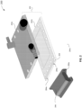
- FIG. 2 illustrates an exploded view of components used to implement cooling using adjustable thermal coupling, in accordance with various embodiments.
- Diagram 200 shows a liquid-cooled cold plate 202 that may be similar to liquid-cooled cold plate 102 of FIG. 1 .
- the liquid-cooled cold plate 202 may include a liquid-cooled sub plate 202a that may be thermally and/or mechanically coupled to a sub plate 202b.
- a thermal interface material (TIM) (not shown) may be used to thermally couple the liquid-cooled sub plate 202a and the sub plate 202b to form the liquid-cooled sub plate 202.
- TIM thermal interface material
- a thermal interface plane 204 may be mechanically and/or thermally coupled to the liquid-cooled cold plate 202. In embodiments, this coupling may be immobile and/or fixed. In embodiments, the thermal interface plane 204 may be mechanically and/or thermally coupled to the liquid-cooled sub plate 202a or the sub plate 202b. In embodiments, the thermal interface plane 204 includes one or more attachment features 204a to implement an adjustable thermal coupling with a VR cold plate 206, which may be similar to the VR cold plate 106 of FIG. 1 . In embodiments, the adjustable coupling via the thermal interface plane 204 may allow the VR cold plate 206 to be mechanically and thermally coupled to the liquid-cooled cold plate 202.
- the VR cold plate 206 may include one or more attachment features 206a to implement an adjustable coupling when used in conjunction with one or more attachment features 204a of the thermal interface plane 204.
- an adjustable coupling may include one or more fasteners that may be inserted through a thermal interface plane attachment feature 204a and fastened to a VR cold plate attachment feature 206a.
- Fastener 308 of FIG. 3 may be one non-limiting example of a fastener.
- a fastener may be a threaded screw, a threaded bolt, a rivet, or some other fastener.
- the VR cold plate attachment feature 206a is an elongated hole to receive a fastener.
- An elongated hole may allow a degree of freedom along an axis providing a plurality of relative positions at which a thermal and/or mechanical connection between the VR cold plate 206 and the thermal interface plane 204 may be set. In embodiments, this plurality of positions may be used to adjust the relative heights of the VR cold plate 206 and the liquid-cooled cold plate 202.
- fasteners may be further manipulated to cause the VR cold plate 206 and the thermal interface plane 204 to be immobily coupled, or fixed, at that position.
- heat may then readily flow from the VR cold plate 206 to the liquid-cooled cold plate 202.
- manipulating the fasters may include screwing in the fasteners to cause the VR cold plate to be securely pressed against the thermal interface plane 204.
- thermal conductivity may be enhanced by configuring the surfaces of the VR cold plate 206 and of the thermal interface plane 204 that come into contact. In non-limiting examples, these surfaces may be flat, or may be of some other shape to maximize the material contact, and therefore thermal conductivity, between the VR cold plate 206 and the thermal interface plane 204.
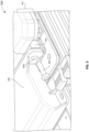
- FIG. 3 illustrates an exploded view of adjustable thermal coupling between a liquid-cooled cold plate and another cold plate, in accordance with various embodiments.
- Diagram 300 shows a VR cold plate 306, which may be similar to the VR cold plate 206 of FIG. 2 and the VR cold plate attachment feature 306a, which may be similar to the VR cold plate attachment feature 206a of FIG. 2 .
- a fastener 308 is to be inserted through the VR cold plate attachment feature 306a and into the attachment feature (not shown) of the thermal interface plane 304, which may be similar to the thermal interface plane 204 of FIG. 2 .
- the thermal interface plane 304 may be immobily and thermally coupled to the liquid-cooled cold plate 302, which may be similar to the liquid-cooled cold plate 202 of FIG. 2 .
- the VR cold plate attachment feature 306a may be elongated to allow the relative position of the VR cold plate 306 to move up and down relative to the position of the thermal interface plane 304 while the fastener 308 is inserted but not yet tightened.
- the VR cold plate attachment feature 306a may take other shapes that may be used to allow the VR cold plate 306 to move in other directions prior to the fastener 308 being secured to the thermal interface plane 304. For example if the VR cold plate 306 needed to be adjusted laterally with respect to the PCB in order to thermally couple with a VR component (not shown), the VR cold plate attachment feature 306a may be elongated in a horizontal direction.
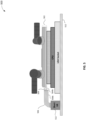
- FIG. 4 illustrates a first example of an adjustable thermal coupling configured for a tall voltage regulator, in accordance with various embodiments.
- a voltage regulator may be considered a tall voltage regulator if it has a height in the Z-dimension higher than the combined height in the Z-dimension of the CPU 414 and the socket 415, presenting a potential coupling issue for the CPU and VR cold plates.
- An example of socket 415 may be, but is not limited to, a land grid array (LGA) socket.
- Figure 400 shows a first side view of a liquid-cooled cold plate 402, which may be similar to liquid-cooled cold plate 202 of FIG. 2 that may be cooling a CPU 414 attached to a PCB 408.
- a VR component 410, attached to the PCB 408, may be thermally coupled to a VR cold plate 406, which may be similar to the VR cold plate 206 of FIG. 2 .
- the VR cold plate 406 may be thermally coupled to the thermal interface plane 404, which may be similar to the thermal interface plane 204 of FIG. 2 .
- the liquid-cooled cold plate 402 may be immobily attached to the thermal interface plane 404.
- the VR component 410 may be taller with respect to a height perpendicular to the PCB 408.
- the VR cold plate 406 and the thermal interface plane 404 may be adjusted such that the bottom of the VR cold plate 406b and the bottom of the thermal interface plane 404b may be aligned as shown. As a result, this will create a mechanical and/or thermal coupling between the VR cold plate 406 and the liquid-cooled cold plate 402 that may be properly adapted to the height of the VR component 410 without placing undue torque on the PCB 408.
- FIG. 5 illustrates a second example of an adjustable thermal coupling configured for a short voltage regulator, in accordance with various embodiments.
- a voltage regulator may be considered a short voltage regulator if it has a height in the Z-dimension shorter the combined height in the Z-dimension of the CPU and the socket, presenting a potential coupling issue for the CPU and VR cold plates.
- Diagram 500 shows a second side view that is similar to diagram 400 of FIG. 4 , except that the VR component 512 has a shorter height than the VR component 412 of FIG. 4 .
- the relative positions of the VR cold plate 506 and the thermal interface plane 504 may be adjusted to be in a position that is different than that shown for thermal interface plane 404 in FIG. 4 .
- the bottom of the VR cold plate 506b is not in alignment with the bottom of the thermal interface plane 504c. Because of the shorter height of the VR component 512, a different alignment from that shown in FIG. 4 is needed to create a mechanical and/or thermal coupling between the VR cold plate 506 and the liquid-cooled cold plate 502 without placing undue torque on the PCB 508.
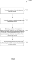
- FIG. 6 illustrates a block diagram of a process for implementing an adjustable thermal coupling between a liquid-cooled cold plate coupled to a CPU and a cold plate thermally coupled to a voltage regulator, in accordance with various embodiments.
- the process 600 may be implemented using the VR cooling plate 206, VR cooling plate attachment features 206a, thermal interface plane 204, thermal interface plane attachment features 204a, and liquid-cooled cooling plate 202 of FIG. 2 , and the fastener 308 of FIG. 3 .
- the process includes thermally coupling a first cold plate to a first heat source.
- the first heat source may be a VR component 410 of FIG. 4 .
- the first cold plate may be the VR cold plate 206 of FIG. 2 .
- the thermal coupling may include mechanically coupling the VR cold plate 206 with the VR component 410 so that heat may be readily transferred between the components.
- a thermal interface material may be used to thermally couple the VR cold plate 206 and VR component 410.
- the process includes thermally coupling a second cold plate to a second heat source.
- the second heat source may be a CPU 414 of FIG. 4 .
- the second cold plate may be the liquid-cooled cold plate 202 of FIG. 2 .
- the thermal coupling may include mechanically coupling the CPU 414 with the liquid-cooled cold plate 212 so that heat may be readily transferred between the components.
- a thermal interface material may be used to thermally couple the CPU 414 with the liquid-cooled cold plate 212.
- the process includes selecting a position of an adjustment feature to thermally couple the first cold plate to the second cold plate, wherein the adjustment feature is to provide a degree of freedom along an axis in accommodating a dimension requirement of the second heat source.
- the adjustment feature may include the thermal interface plane 404 of FIG. 4 that may be mechanically and/or thermally coupled to the first cold plate, which may be a VR cold plate 406 and to the second cold plate, which may be the liquid-cooled cold plate 402.
- an adjustment feature may enable thermal coupling between the thermal interface plane 404 and the VR cold plate 406 in a variety of positions.
- the adjustment feature may provide a degree of freedom along an axis representing a height of the VR component 410 above the PCB 408.
- the process includes securing the adjustment feature to cause the first cold plate and the second cold plate to be immobily coupled.
- the thermal interface plane 304 may be immobily coupled to the liquid-cooled cold plate 302 of FIG. 3 .
- Securing the adjustment feature may include modifying the fastener 308 of FIG. 3 that may be inserted into the VR cold plate attachment feature 306a.
- the fastener 308 may be a threaded bolt that is tightened into a threaded hole within the thermal interface plane 304 to immobily couple the VR cold plate 306 to the liquid-cooled cold plate 302. The result of this immobile coupling may be to immobily couple the VR cold plate 304 and the liquid-cooled cold plate 302.
- the process may result in efficient heat flow from the VR to the liquid-cooled cold plate of the CPU that minimizes torque on the PCB on which the VR component and the CPU may be attached.
Landscapes
- Engineering & Computer Science (AREA)
- Microelectronics & Electronic Packaging (AREA)
- Physics & Mathematics (AREA)
- Thermal Sciences (AREA)
- Theoretical Computer Science (AREA)
- General Engineering & Computer Science (AREA)
- Human Computer Interaction (AREA)
- General Physics & Mathematics (AREA)
- Mechanical Engineering (AREA)
- Cooling Or The Like Of Electrical Apparatus (AREA)
- Cooling Or The Like Of Semiconductors Or Solid State Devices (AREA)
Claims (11)
- Kühleinrichtung (100, 200, 300, 400, 500), umfassend:eine erste Kälteplatte (102, 202, 302, 402, 502), die mit einer ersten Wärmequelle thermisch koppelbar ist;eine zweite Kälteplatte (106, 206, 306, 406, 506), die mit einer zweiten Wärmequelle thermisch koppelbar ist;eine thermische Schnittstellenebene (104, 204, 304, 404, 504), die mit der ersten Kälteplatte (102, 202, 302, 402, 502) gekoppelt ist und eine einstellbare Kopplung bereitstellt, um die erste Kälteplatte (102, 202, 302, 402, 502) mit der zweiten Kälteplatte (106, 206, 306, 406, 506) an einer Position einer Mehrzahl von Positionen mechanisch und thermisch zu koppeln, wobei die thermische Schnittstellenebene (104, 204, 304, 404, 504) ein oder mehrere erste Befestigungsmerkmale (204a) umfasst, und wobei die zweite Kälteplatte (106, 206, 306, 406, 506) ein oder mehrere zweite Befestigungsmerkmale (206a, 306a) umfasst, um die einstellbare Kopplung bei Verwendung in Verbindung mit dem einen oder den mehreren ersten Befestigungsmerkmalen (204a) der thermischen Schnittstellenebene (104, 204, 304, 404, 504) zu implementieren, wobei das eine oder die mehreren Befestigungsmerkmale (206a, 306a) als ein Langloch in einem Flansch der zweiten Kälteplatte (106, 206, 306, 406, 506) bereitgestellt sind, das dazu ausgelegt ist, ein Befestigungselement (308) aufzunehmen, wobei das Langloch dazu ausgelegt ist, einen Freiheitsgrad entlang einer Achse bereitzustellen, um die Mehrzahl von Positionen zum Einstellen relativer Höhen der ersten Kälteplatte (102, 202, 302, 402, 502) und der zweiten Kälteplatte (106, 206, 306, 406, 506) bereitzustellen.
- Kühleinrichtung (100, 200, 300, 400, 500) nach Anspruch 1, wobei das Befestigungselement (308) eine Gewindeschraube oder ein Gewindebolzen ist, die bzw. der durch das Langloch in die thermische Schnittstellenebene (104, 204, 304, 404, 504) einsetzbar ist.
- Kühleinrichtung (100, 200, 300, 400, 500) nach Anspruch 1, wobei das thermische Koppeln der ersten Kälteplatte (102, 202, 302, 402, 502) mit der zweiten Kälteplatte (106, 206, 306, 406, 506) thermisches Koppeln einer Fläche der thermischen Schnittstellenebene (104, 204, 304, 404, 504) mit einer Fläche der zweiten Kälteplatte (106, 206, 306, 406, 506) umfasst.
- Kühleinrichtung (100, 200, 300, 400, 500) nach Anspruch 3, wobei die Fläche der thermischen Schnittstellenebene (104, 204, 304, 404, 504) und die Fläche der zweiten Kälteplatte (106, 206, 306, 406, 506) in einer Mehrzahl von Auslegungen thermisch gekoppelt werden können.
- Kühleinrichtung (100, 200, 300, 400, 500) nach Anspruch 1, wobei das eine oder die mehreren zweiten Einstellungsmerkmale (206a, 306a) die erste Kälteplatte (102, 202, 302, 402, 502) und die zweite Kälteplatte (106, 206, 306, 406, 506) veranlassen sollen, unbeweglich gekoppelt zu werden.
- Kühleinrichtung (100, 200, 300, 400, 500) nach Anspruch 5, wobei die erste Wärmequelle und die zweite Wärmequelle auf derselben gedruckten Leiterplatte, PCB (408) befestigt sind.
- Kühleinrichtung (100, 200, 300, 400, 500) nach Anspruch 6, wobei das unbewegliche Koppeln ein Drehmoment auf die PCB (408) weiter reduzieren soll.
- Verfahren (600) zum Kühlen einer Einrichtung, wobei das Verfahren Folgendes umfasst:thermisches Koppeln (602) einer ersten Kälteplatte (102, 202, 302, 402, 502) mit einer ersten Wärmequelle;thermisches Koppeln (604) einer zweiten Kälteplatte (106, 206, 306, 406, 506) mit einer zweiten Wärmequelle;Auswählen, aus einer Mehrzahl von Positionen, einer Position (606) einer thermischen Schnittstellenebene (104, 204, 304, 404, 504), die mit der ersten Kälteplatte (102, 202, 302, 402, 502) gekoppelt ist, für eine einstellbare Kopplung, um die erste Kälteplatte (102, 202, 302, 402, 502) mit der zweiten Kälteplatte (106, 206, 306, 406, 506) mechanisch und thermisch zu koppeln,wobei die thermische Schnittstellenebene (104, 204, 304, 404, 504) ein oder mehrere erste Befestigungsmerkmale (204a) umfasst, und wobei die zweite Kälteplatte (106, 206, 306, 406, 506) ein oder mehrere zweite Befestigungsmerkmale (206a, 306a) umfasst, um die einstellbare Kopplung bei Verwendung in Verbindung mit dem einen oder den mehreren ersten Befestigungsmerkmalen (204a) der thermischen Schnittstellenebene (104, 204, 304, 404, 504) zu implementieren, wobei das eine oder die mehreren Befestigungsmerkmale (206a, 306a) als ein Langloch in einem Flansch der zweiten Kälteplatte (106, 206, 306, 406, 506) bereitgestellt sind, das dazu ausgelegt ist, ein Befestigungselement (308) aufzunehmen, wobei das Langloch dazu ausgelegt ist, einen Freiheitsgrad entlang einer Achse bereitzustellen, um die Mehrzahl von Positionen zum Einstellen relativer Höhen der ersten Kälteplatte (102, 202, 302, 402, 502) und der zweiten Kälteplatte (106, 206, 306, 406, 506) bereitzustellen; undSichern (608) der Befestigungsmerkmale (204a, 206a, 306a), um die erste Kälteplatte (102, 202, 302, 402, 502) und die zweite Kälteplatte (106, 206, 306, 406, 506) zu veranlassen, unbeweglich gekoppelt zu werden, wobei Sichern der Befestigungsmerkmale (204a, 206a, 306a) Aufnehmen eines Befestigungselements (308) durch das Langloch umfasst.
- Verfahren (600) nach Anspruch 8, wobei Aufnehmen des Befestigungselements (308) durch das Langloch Einsetzen einer Gewindeschraube oder eines Gewindebolzens durch das Langloch in der zweiten Kälteplatte (106, 206, 306, 406, 506) in die erste Kälteplatte (102, 202, 302, 402, 502) umfasst.
- Verfahren (600) nach Anspruch 8, wobei thermisches Koppeln der ersten Kälteplatte (102, 202, 302, 402, 502) mit der zweiten Kälteplatte (106, 206, 306, 406, 506) thermisches Koppeln einer Fläche der ersten Kälteplatte (102, 202, 302, 402, 502) mit einer Fläche der zweiten Kälteplatte (106, 206, 306, 406, 506) umfasst.
- Verfahren (600) nach Anspruch 10, wobei die Fläche der ersten Kälteplatte (102, 202, 302, 402, 502) und die Fläche der zweiten Kälteplatte (106, 206, 306, 406, 506) in einer Mehrzahl von Auslegungen thermisch gekoppelt werden können.
Applications Claiming Priority (2)
| Application Number | Priority Date | Filing Date | Title |
|---|---|---|---|
| US15/366,799 US10168749B2 (en) | 2016-12-01 | 2016-12-01 | Cooling using adjustable thermal coupling |
| PCT/US2017/055174 WO2018102027A1 (en) | 2016-12-01 | 2017-10-04 | Cooling using adjustable thermal coupling |
Publications (3)
| Publication Number | Publication Date |
|---|---|
| EP3548986A1 EP3548986A1 (de) | 2019-10-09 |
| EP3548986A4 EP3548986A4 (de) | 2020-07-22 |
| EP3548986B1 true EP3548986B1 (de) | 2023-11-01 |
Family
ID=62241781
Family Applications (1)
| Application Number | Title | Priority Date | Filing Date |
|---|---|---|---|
| EP17876717.4A Active EP3548986B1 (de) | 2016-12-01 | 2017-10-04 | Kühlung mithilfe verstellbarer thermischer kopplung |
Country Status (3)
| Country | Link |
|---|---|
| US (1) | US10168749B2 (de) |
| EP (1) | EP3548986B1 (de) |
| WO (1) | WO2018102027A1 (de) |
Families Citing this family (6)
| Publication number | Priority date | Publication date | Assignee | Title |
|---|---|---|---|---|
| FR3075560B1 (fr) * | 2017-12-15 | 2020-10-16 | Bull Sas | Systeme de refroidissement liquide pour carte electronique constituee d'une plaque froide et de dissipateurs thermiques relies en liaisons souples avec ladite plaque froide |
| US10548239B1 (en) * | 2018-10-23 | 2020-01-28 | Google Llc | Cooling electronic devices in a data center |
| US11416045B2 (en) | 2020-04-13 | 2022-08-16 | International Business Machines Corporation | Thermal interface material structures for directing heat in a three-dimensional space |
| US11310938B2 (en) * | 2020-06-09 | 2022-04-19 | Dell Products, L.P. | Leak sensor drip tray |
| US12055986B2 (en) * | 2021-02-26 | 2024-08-06 | Intel Corporation | Flexible and modular top and bottom side processor unit module cooling |
| US11749923B2 (en) | 2021-04-15 | 2023-09-05 | Te Connectivity Solutions Gmbh | Cooling system for socket connector |
Family Cites Families (18)
| Publication number | Priority date | Publication date | Assignee | Title |
|---|---|---|---|---|
| US5829516A (en) | 1993-12-15 | 1998-11-03 | Aavid Thermal Products, Inc. | Liquid cooled heat sink for cooling electronic components |
| US6191945B1 (en) | 1997-07-30 | 2001-02-20 | Hewlett-Packard Company | Cold plate arrangement for cooling processor and companion voltage regulator |
| US6452804B1 (en) | 1999-07-15 | 2002-09-17 | Incep Technologies, Inc. | Method and apparatus for thermal and mechanical management of a power regulator module and microprocessor in contact with a thermally conducting plate |
| US6285550B1 (en) | 2000-01-04 | 2001-09-04 | Hewlett Packard Company | Sub-cooled processor and companion voltage regulator |
| US7971632B2 (en) | 2003-11-07 | 2011-07-05 | Asetek A/S | Cooling system for a computer system |
| US7149087B2 (en) | 2004-09-08 | 2006-12-12 | Thermal Corp. | Liquid cooled heat sink with cold plate retention mechanism |
| US7298622B2 (en) * | 2005-06-15 | 2007-11-20 | Tyco Electronics Corporation | Modular heat sink assembly |
| US7385824B2 (en) | 2005-07-29 | 2008-06-10 | Hewlett-Packard Development Company, L.P. | Processor module with rigidly coupled processor and voltage-regulator heat sinks |
| US7362583B2 (en) * | 2005-12-30 | 2008-04-22 | Ati Technologies Inc. | Thermal management device for multiple heat producing devices |
| US20070227709A1 (en) | 2006-03-30 | 2007-10-04 | Girish Upadhya | Multi device cooling |
| US7420808B2 (en) | 2006-10-10 | 2008-09-02 | International Business Machines Corporation | Liquid-based cooling system for cooling a multi-component electronics system |
| US8498117B2 (en) | 2006-11-16 | 2013-07-30 | Advanced Micro Devices, Inc. | Variable mount voltage regulator |
| EP2294496B1 (de) | 2008-05-21 | 2017-06-28 | Asetek A/S | Thermisches zwischenglied für grafikkarten |
| JP6090429B2 (ja) | 2013-03-21 | 2017-03-08 | 日本電気株式会社 | ヒートシンク構造、半導体装置及びヒートシンク搭載方法 |
| US9210831B2 (en) | 2013-04-15 | 2015-12-08 | International Business Machines Corporation | Separable and integrated heat sinks facilitating cooling multi-compnent electronic assembly |
| US9310859B2 (en) | 2013-11-12 | 2016-04-12 | International Business Machines Corporation | Liquid cooling of multiple components on a circuit board |
| WO2015187748A1 (en) | 2014-06-02 | 2015-12-10 | Corsair Memory, Inc. | Graphics card cooler |
| US9490188B2 (en) | 2014-09-12 | 2016-11-08 | International Business Machines Corporation | Compute intensive module packaging |
-
2016
- 2016-12-01 US US15/366,799 patent/US10168749B2/en active Active
-
2017
- 2017-10-04 WO PCT/US2017/055174 patent/WO2018102027A1/en not_active Ceased
- 2017-10-04 EP EP17876717.4A patent/EP3548986B1/de active Active
Also Published As
| Publication number | Publication date |
|---|---|
| WO2018102027A1 (en) | 2018-06-07 |
| US10168749B2 (en) | 2019-01-01 |
| US20180157296A1 (en) | 2018-06-07 |
| EP3548986A4 (de) | 2020-07-22 |
| EP3548986A1 (de) | 2019-10-09 |
Similar Documents
| Publication | Publication Date | Title |
|---|---|---|
| EP3548986B1 (de) | Kühlung mithilfe verstellbarer thermischer kopplung | |
| CN111989990B (zh) | 在数据中心中冷却电子装置 | |
| US5926370A (en) | Method and apparatus for a modular integrated apparatus for multi-function components | |
| US5930114A (en) | Heat sink mounting assembly for surface mount electronic device packages | |
| CN105338790B (zh) | 用于电气装置内的构件的被动冷却的系统和方法 | |
| US7212404B2 (en) | Integrated heat sink device | |
| EP3872601B1 (de) | Wärmeableitungsvorrichtung | |
| EP3573438B1 (de) | Fernwärmetauscher | |
| US20090213541A1 (en) | Cooling Plate Assembly with Fixed and Articulated Interfaces, and Method for Producing Same | |
| US8693200B2 (en) | Semiconductor device cooling module | |
| US20080310119A1 (en) | Clip on heat sink | |
| US10962297B2 (en) | Multidimensional heat transfer system for cooling electronic components | |
| US20110013363A1 (en) | Housing Used As Heat Collector | |
| US8422226B2 (en) | Heat dissipation device | |
| US7265974B2 (en) | Multi-heatsink integrated cooling device | |
| JP2009130224A (ja) | 電子機器用の冷却装置 | |
| US20070025086A1 (en) | Electronic device with sliding type heatsink | |
| CN113316349B (zh) | 散热装置 | |
| CN217689993U (zh) | 电源装置和具有电源装置的计算设备 | |
| WO2020103156A1 (zh) | 电路板及计算设备 | |
| WO2005059994A1 (en) | Structure for air conduction in radiator device | |
| TW202549465A (zh) | 冷熱交換裝置 | |
| JP7089512B2 (ja) | 電子カード用の放熱装置 | |
| RU2667360C1 (ru) | Способ обеспечения пассивного теплоотвода процессора мобильного устройства либо переносного компьютера на основе алмаз-медного композиционного материала и устройство для его осуществления | |
| CN121619837A (zh) | 一种水冷散热式电源结构及其制造方法 |
Legal Events
| Date | Code | Title | Description |
|---|---|---|---|
| STAA | Information on the status of an ep patent application or granted ep patent |
Free format text: STATUS: THE INTERNATIONAL PUBLICATION HAS BEEN MADE |
|
| PUAI | Public reference made under article 153(3) epc to a published international application that has entered the european phase |
Free format text: ORIGINAL CODE: 0009012 |
|
| STAA | Information on the status of an ep patent application or granted ep patent |
Free format text: STATUS: REQUEST FOR EXAMINATION WAS MADE |
|
| 17P | Request for examination filed |
Effective date: 20190419 |
|
| AK | Designated contracting states |
Kind code of ref document: A1 Designated state(s): AL AT BE BG CH CY CZ DE DK EE ES FI FR GB GR HR HU IE IS IT LI LT LU LV MC MK MT NL NO PL PT RO RS SE SI SK SM TR |
|
| AX | Request for extension of the european patent |
Extension state: BA ME |
|
| DAV | Request for validation of the european patent (deleted) | ||
| DAX | Request for extension of the european patent (deleted) | ||
| A4 | Supplementary search report drawn up and despatched |
Effective date: 20200619 |
|
| RIC1 | Information provided on ipc code assigned before grant |
Ipc: H05K 7/20 20060101ALI20200615BHEP Ipc: G06F 1/20 20060101AFI20200615BHEP |
|
| STAA | Information on the status of an ep patent application or granted ep patent |
Free format text: STATUS: EXAMINATION IS IN PROGRESS |
|
| 17Q | First examination report despatched |
Effective date: 20220301 |
|
| GRAP | Despatch of communication of intention to grant a patent |
Free format text: ORIGINAL CODE: EPIDOSNIGR1 |
|
| STAA | Information on the status of an ep patent application or granted ep patent |
Free format text: STATUS: GRANT OF PATENT IS INTENDED |
|
| INTG | Intention to grant announced |
Effective date: 20230526 |
|
| GRAS | Grant fee paid |
Free format text: ORIGINAL CODE: EPIDOSNIGR3 |
|
| GRAA | (expected) grant |
Free format text: ORIGINAL CODE: 0009210 |
|
| STAA | Information on the status of an ep patent application or granted ep patent |
Free format text: STATUS: THE PATENT HAS BEEN GRANTED |
|
| AK | Designated contracting states |
Kind code of ref document: B1 Designated state(s): AL AT BE BG CH CY CZ DE DK EE ES FI FR GB GR HR HU IE IS IT LI LT LU LV MC MK MT NL NO PL PT RO RS SE SI SK SM TR |
|
| REG | Reference to a national code |
Ref country code: GB Ref legal event code: FG4D |
|
| REG | Reference to a national code |
Ref country code: CH Ref legal event code: EP |
|
| REG | Reference to a national code |
Ref country code: DE Ref legal event code: R096 Ref document number: 602017076148 Country of ref document: DE |
|
| P01 | Opt-out of the competence of the unified patent court (upc) registered |
Effective date: 20231012 |
|
| REG | Reference to a national code |
Ref country code: IE Ref legal event code: FG4D |
|
| REG | Reference to a national code |
Ref country code: NL Ref legal event code: FP |
|
| REG | Reference to a national code |
Ref country code: LT Ref legal event code: MG9D |
|
| PG25 | Lapsed in a contracting state [announced via postgrant information from national office to epo] |
Ref country code: GR Free format text: LAPSE BECAUSE OF FAILURE TO SUBMIT A TRANSLATION OF THE DESCRIPTION OR TO PAY THE FEE WITHIN THE PRESCRIBED TIME-LIMIT Effective date: 20240202 |
|
| PG25 | Lapsed in a contracting state [announced via postgrant information from national office to epo] |
Ref country code: IS Free format text: LAPSE BECAUSE OF FAILURE TO SUBMIT A TRANSLATION OF THE DESCRIPTION OR TO PAY THE FEE WITHIN THE PRESCRIBED TIME-LIMIT Effective date: 20240301 |
|
| PG25 | Lapsed in a contracting state [announced via postgrant information from national office to epo] |
Ref country code: LT Free format text: LAPSE BECAUSE OF FAILURE TO SUBMIT A TRANSLATION OF THE DESCRIPTION OR TO PAY THE FEE WITHIN THE PRESCRIBED TIME-LIMIT Effective date: 20231101 |
|
| REG | Reference to a national code |
Ref country code: AT Ref legal event code: MK05 Ref document number: 1627940 Country of ref document: AT Kind code of ref document: T Effective date: 20231101 |
|
| PG25 | Lapsed in a contracting state [announced via postgrant information from national office to epo] |
Ref country code: AT Free format text: LAPSE BECAUSE OF FAILURE TO SUBMIT A TRANSLATION OF THE DESCRIPTION OR TO PAY THE FEE WITHIN THE PRESCRIBED TIME-LIMIT Effective date: 20231101 |
|
| PG25 | Lapsed in a contracting state [announced via postgrant information from national office to epo] |
Ref country code: ES Free format text: LAPSE BECAUSE OF FAILURE TO SUBMIT A TRANSLATION OF THE DESCRIPTION OR TO PAY THE FEE WITHIN THE PRESCRIBED TIME-LIMIT Effective date: 20231101 |
|
| PG25 | Lapsed in a contracting state [announced via postgrant information from national office to epo] |
Ref country code: LT Free format text: LAPSE BECAUSE OF FAILURE TO SUBMIT A TRANSLATION OF THE DESCRIPTION OR TO PAY THE FEE WITHIN THE PRESCRIBED TIME-LIMIT Effective date: 20231101 Ref country code: IS Free format text: LAPSE BECAUSE OF FAILURE TO SUBMIT A TRANSLATION OF THE DESCRIPTION OR TO PAY THE FEE WITHIN THE PRESCRIBED TIME-LIMIT Effective date: 20240301 Ref country code: GR Free format text: LAPSE BECAUSE OF FAILURE TO SUBMIT A TRANSLATION OF THE DESCRIPTION OR TO PAY THE FEE WITHIN THE PRESCRIBED TIME-LIMIT Effective date: 20240202 Ref country code: ES Free format text: LAPSE BECAUSE OF FAILURE TO SUBMIT A TRANSLATION OF THE DESCRIPTION OR TO PAY THE FEE WITHIN THE PRESCRIBED TIME-LIMIT Effective date: 20231101 Ref country code: BG Free format text: LAPSE BECAUSE OF FAILURE TO SUBMIT A TRANSLATION OF THE DESCRIPTION OR TO PAY THE FEE WITHIN THE PRESCRIBED TIME-LIMIT Effective date: 20240201 Ref country code: AT Free format text: LAPSE BECAUSE OF FAILURE TO SUBMIT A TRANSLATION OF THE DESCRIPTION OR TO PAY THE FEE WITHIN THE PRESCRIBED TIME-LIMIT Effective date: 20231101 Ref country code: PT Free format text: LAPSE BECAUSE OF FAILURE TO SUBMIT A TRANSLATION OF THE DESCRIPTION OR TO PAY THE FEE WITHIN THE PRESCRIBED TIME-LIMIT Effective date: 20240301 |
|
| PG25 | Lapsed in a contracting state [announced via postgrant information from national office to epo] |
Ref country code: SE Free format text: LAPSE BECAUSE OF FAILURE TO SUBMIT A TRANSLATION OF THE DESCRIPTION OR TO PAY THE FEE WITHIN THE PRESCRIBED TIME-LIMIT Effective date: 20231101 Ref country code: RS Free format text: LAPSE BECAUSE OF FAILURE TO SUBMIT A TRANSLATION OF THE DESCRIPTION OR TO PAY THE FEE WITHIN THE PRESCRIBED TIME-LIMIT Effective date: 20231101 Ref country code: PL Free format text: LAPSE BECAUSE OF FAILURE TO SUBMIT A TRANSLATION OF THE DESCRIPTION OR TO PAY THE FEE WITHIN THE PRESCRIBED TIME-LIMIT Effective date: 20231101 Ref country code: NO Free format text: LAPSE BECAUSE OF FAILURE TO SUBMIT A TRANSLATION OF THE DESCRIPTION OR TO PAY THE FEE WITHIN THE PRESCRIBED TIME-LIMIT Effective date: 20240201 Ref country code: LV Free format text: LAPSE BECAUSE OF FAILURE TO SUBMIT A TRANSLATION OF THE DESCRIPTION OR TO PAY THE FEE WITHIN THE PRESCRIBED TIME-LIMIT Effective date: 20231101 Ref country code: HR Free format text: LAPSE BECAUSE OF FAILURE TO SUBMIT A TRANSLATION OF THE DESCRIPTION OR TO PAY THE FEE WITHIN THE PRESCRIBED TIME-LIMIT Effective date: 20231101 |
|
| PG25 | Lapsed in a contracting state [announced via postgrant information from national office to epo] |
Ref country code: DK Free format text: LAPSE BECAUSE OF FAILURE TO SUBMIT A TRANSLATION OF THE DESCRIPTION OR TO PAY THE FEE WITHIN THE PRESCRIBED TIME-LIMIT Effective date: 20231101 |
|
| PG25 | Lapsed in a contracting state [announced via postgrant information from national office to epo] |
Ref country code: CZ Free format text: LAPSE BECAUSE OF FAILURE TO SUBMIT A TRANSLATION OF THE DESCRIPTION OR TO PAY THE FEE WITHIN THE PRESCRIBED TIME-LIMIT Effective date: 20231101 |
|
| PG25 | Lapsed in a contracting state [announced via postgrant information from national office to epo] |
Ref country code: SK Free format text: LAPSE BECAUSE OF FAILURE TO SUBMIT A TRANSLATION OF THE DESCRIPTION OR TO PAY THE FEE WITHIN THE PRESCRIBED TIME-LIMIT Effective date: 20231101 |
|
| PG25 | Lapsed in a contracting state [announced via postgrant information from national office to epo] |
Ref country code: SM Free format text: LAPSE BECAUSE OF FAILURE TO SUBMIT A TRANSLATION OF THE DESCRIPTION OR TO PAY THE FEE WITHIN THE PRESCRIBED TIME-LIMIT Effective date: 20231101 Ref country code: SK Free format text: LAPSE BECAUSE OF FAILURE TO SUBMIT A TRANSLATION OF THE DESCRIPTION OR TO PAY THE FEE WITHIN THE PRESCRIBED TIME-LIMIT Effective date: 20231101 Ref country code: IT Free format text: LAPSE BECAUSE OF FAILURE TO SUBMIT A TRANSLATION OF THE DESCRIPTION OR TO PAY THE FEE WITHIN THE PRESCRIBED TIME-LIMIT Effective date: 20231101 Ref country code: EE Free format text: LAPSE BECAUSE OF FAILURE TO SUBMIT A TRANSLATION OF THE DESCRIPTION OR TO PAY THE FEE WITHIN THE PRESCRIBED TIME-LIMIT Effective date: 20231101 Ref country code: DK Free format text: LAPSE BECAUSE OF FAILURE TO SUBMIT A TRANSLATION OF THE DESCRIPTION OR TO PAY THE FEE WITHIN THE PRESCRIBED TIME-LIMIT Effective date: 20231101 Ref country code: CZ Free format text: LAPSE BECAUSE OF FAILURE TO SUBMIT A TRANSLATION OF THE DESCRIPTION OR TO PAY THE FEE WITHIN THE PRESCRIBED TIME-LIMIT Effective date: 20231101 |
|
| REG | Reference to a national code |
Ref country code: DE Ref legal event code: R097 Ref document number: 602017076148 Country of ref document: DE |
|
| PLBE | No opposition filed within time limit |
Free format text: ORIGINAL CODE: 0009261 |
|
| STAA | Information on the status of an ep patent application or granted ep patent |
Free format text: STATUS: NO OPPOSITION FILED WITHIN TIME LIMIT |
|
| 26N | No opposition filed |
Effective date: 20240802 |
|
| PG25 | Lapsed in a contracting state [announced via postgrant information from national office to epo] |
Ref country code: SI Free format text: LAPSE BECAUSE OF FAILURE TO SUBMIT A TRANSLATION OF THE DESCRIPTION OR TO PAY THE FEE WITHIN THE PRESCRIBED TIME-LIMIT Effective date: 20231101 |
|
| PG25 | Lapsed in a contracting state [announced via postgrant information from national office to epo] |
Ref country code: SI Free format text: LAPSE BECAUSE OF FAILURE TO SUBMIT A TRANSLATION OF THE DESCRIPTION OR TO PAY THE FEE WITHIN THE PRESCRIBED TIME-LIMIT Effective date: 20231101 |
|
| REG | Reference to a national code |
Ref country code: CH Ref legal event code: PL |
|
| GBPC | Gb: european patent ceased through non-payment of renewal fee |
Effective date: 20241004 |
|
| PG25 | Lapsed in a contracting state [announced via postgrant information from national office to epo] |
Ref country code: MC Free format text: LAPSE BECAUSE OF FAILURE TO SUBMIT A TRANSLATION OF THE DESCRIPTION OR TO PAY THE FEE WITHIN THE PRESCRIBED TIME-LIMIT Effective date: 20231101 |
|
| PG25 | Lapsed in a contracting state [announced via postgrant information from national office to epo] |
Ref country code: GB Free format text: LAPSE BECAUSE OF NON-PAYMENT OF DUE FEES Effective date: 20241004 |
|
| PG25 | Lapsed in a contracting state [announced via postgrant information from national office to epo] |
Ref country code: BE Free format text: LAPSE BECAUSE OF NON-PAYMENT OF DUE FEES Effective date: 20241031 Ref country code: LU Free format text: LAPSE BECAUSE OF NON-PAYMENT OF DUE FEES Effective date: 20241004 |
|
| PG25 | Lapsed in a contracting state [announced via postgrant information from national office to epo] |
Ref country code: FR Free format text: LAPSE BECAUSE OF NON-PAYMENT OF DUE FEES Effective date: 20241031 |
|
| PG25 | Lapsed in a contracting state [announced via postgrant information from national office to epo] |
Ref country code: CH Free format text: LAPSE BECAUSE OF NON-PAYMENT OF DUE FEES Effective date: 20241031 |
|
| REG | Reference to a national code |
Ref country code: BE Ref legal event code: MM Effective date: 20241031 |
|
| PG25 | Lapsed in a contracting state [announced via postgrant information from national office to epo] |
Ref country code: FI Free format text: LAPSE BECAUSE OF FAILURE TO SUBMIT A TRANSLATION OF THE DESCRIPTION OR TO PAY THE FEE WITHIN THE PRESCRIBED TIME-LIMIT Effective date: 20231101 |
|
| PGFP | Annual fee paid to national office [announced via postgrant information from national office to epo] |
Ref country code: NL Payment date: 20250924 Year of fee payment: 9 |
|
| PG25 | Lapsed in a contracting state [announced via postgrant information from national office to epo] |
Ref country code: IE Free format text: LAPSE BECAUSE OF NON-PAYMENT OF DUE FEES Effective date: 20241004 |
|
| PG25 | Lapsed in a contracting state [announced via postgrant information from national office to epo] |
Ref country code: RO Free format text: LAPSE BECAUSE OF FAILURE TO SUBMIT A TRANSLATION OF THE DESCRIPTION OR TO PAY THE FEE WITHIN THE PRESCRIBED TIME-LIMIT Effective date: 20231101 |
|
| PGFP | Annual fee paid to national office [announced via postgrant information from national office to epo] |
Ref country code: DE Payment date: 20250916 Year of fee payment: 9 |
|
| PG25 | Lapsed in a contracting state [announced via postgrant information from national office to epo] |
Ref country code: CY Free format text: LAPSE BECAUSE OF FAILURE TO SUBMIT A TRANSLATION OF THE DESCRIPTION OR TO PAY THE FEE WITHIN THE PRESCRIBED TIME-LIMIT; INVALID AB INITIO Effective date: 20171004 |
|
| PG25 | Lapsed in a contracting state [announced via postgrant information from national office to epo] |
Ref country code: HU Free format text: LAPSE BECAUSE OF FAILURE TO SUBMIT A TRANSLATION OF THE DESCRIPTION OR TO PAY THE FEE WITHIN THE PRESCRIBED TIME-LIMIT; INVALID AB INITIO Effective date: 20171004 |