EP3549149B1 - Contacteur avec circuit de commande d'inversion de polarité de bobine - Google Patents
Contacteur avec circuit de commande d'inversion de polarité de bobine Download PDFInfo
- Publication number
- EP3549149B1 EP3549149B1 EP17817151.8A EP17817151A EP3549149B1 EP 3549149 B1 EP3549149 B1 EP 3549149B1 EP 17817151 A EP17817151 A EP 17817151A EP 3549149 B1 EP3549149 B1 EP 3549149B1
- Authority
- EP
- European Patent Office
- Prior art keywords
- coil
- actuator
- input circuit
- switches
- contactor
- Prior art date
- Legal status (The legal status is an assumption and is not a legal conclusion. Google has not performed a legal analysis and makes no representation as to the accuracy of the status listed.)
- Active
Links
Images


Classifications
-
- H—ELECTRICITY
- H01—ELECTRIC ELEMENTS
- H01H—ELECTRIC SWITCHES; RELAYS; SELECTORS; EMERGENCY PROTECTIVE DEVICES
- H01H73/00—Protective overload circuit-breaking switches in which excess current opens the contacts by automatic release of mechanical energy stored by previous operation of a hand reset mechanism
- H01H73/02—Details
- H01H73/18—Means for extinguishing or suppressing arc
-
- H—ELECTRICITY
- H01—ELECTRIC ELEMENTS
- H01H—ELECTRIC SWITCHES; RELAYS; SELECTORS; EMERGENCY PROTECTIVE DEVICES
- H01H50/00—Details of electromagnetic relays
- H01H50/02—Bases; Casings; Covers
- H01H50/021—Bases; Casings; Covers structurally combining a relay and an electronic component, e.g. varistor, RC circuit
-
- H—ELECTRICITY
- H01—ELECTRIC ELEMENTS
- H01H—ELECTRIC SWITCHES; RELAYS; SELECTORS; EMERGENCY PROTECTIVE DEVICES
- H01H50/00—Details of electromagnetic relays
- H01H50/02—Bases; Casings; Covers
- H01H50/04—Mounting complete relay or separate parts of relay on a base or inside a case
- H01H50/041—Details concerning assembly of relays
- H01H50/045—Details particular to contactors
-
- H—ELECTRICITY
- H01—ELECTRIC ELEMENTS
- H01H—ELECTRIC SWITCHES; RELAYS; SELECTORS; EMERGENCY PROTECTIVE DEVICES
- H01H51/00—Electromagnetic relays
- H01H51/22—Polarised relays
- H01H51/2209—Polarised relays with rectilinearly movable armature
-
- H—ELECTRICITY
- H01—ELECTRIC ELEMENTS
- H01H—ELECTRIC SWITCHES; RELAYS; SELECTORS; EMERGENCY PROTECTIVE DEVICES
- H01H51/00—Electromagnetic relays
- H01H51/27—Relays with armature having two stable magnetic states and operated by change from one state to the other
-
- H—ELECTRICITY
- H01—ELECTRIC ELEMENTS
- H01H—ELECTRIC SWITCHES; RELAYS; SELECTORS; EMERGENCY PROTECTIVE DEVICES
- H01H89/00—Combinations of two or more different basic types of electric switches, relays, selectors and emergency protective devices, not covered by any single one of the other main groups of this subclass
- H01H89/06—Combination of a manual reset circuit with a contactor, i.e. the same circuit controlled by both a protective and a remote control device
-
- H—ELECTRICITY
- H01—ELECTRIC ELEMENTS
- H01H—ELECTRIC SWITCHES; RELAYS; SELECTORS; EMERGENCY PROTECTIVE DEVICES
- H01H51/00—Electromagnetic relays
- H01H51/22—Polarised relays
- H01H51/2209—Polarised relays with rectilinearly movable armature
- H01H2051/2218—Polarised relays with rectilinearly movable armature having at least one movable permanent magnet
Definitions
- the present invention is directed to a contactor with a coil polarity reversing control circuit.
- the invention is directed to a coil polarity reversing circuit that reverses the magnetic polarity of the coil each occurrence of the actuator being actuated.
- Latching contactors employ two separate coils wound with opposite magnetic polarity to initiate a change of state of the latching contactor.
- Latching contactors employ a first coil that is energized momentarily to transition the contactor from a first state, such as a tripped state, to a next state, such as an operational state, to close the power mains switches and position all other contactor switches in respective states corresponding to the mains switches being in the closed, power-on state.
- a second coil of the opposite magnetic polarity is energized momentarily to transition the contactor to a next state, such as a tripped state, to open the mains switches and position all other contactor switches in respective states corresponding to the mains switches being in the opened, power-off state.
- WO 00/70634 A1 discloses a switch with a coil for moving an armature between first and second positions. A latching relay controls the direction in which current is passed through the coil.
- US 6,507,255 B 1 discloses a circuit breaker having a latching solenoid, which is energized with different polarity signals to move a plunger between first and second positions.
- a contactor includes a plurality of switches, a first input circuit for receiving a power-up input signal and a second input circuit for receiving a trip input signal.
- a movable actuator is mechanically coupled to switches in the plurality of switches. The actuator is moveable between a tripped position and an operational position upon receipt of a power-up input signal on the first input circuit, and moveable between the operational position and the tripped position upon receipt of a trip input signal on the second input circuit.
- a coil has first and second ends. The moveable actuator extends through the coil as a core.
- the coil is capable of moving the actuator when either a power-up input signal is received by the first input circuit or a trip input signal is received by the second input circuit.
- First and second switches are coupled to respective first and second ends of the coil for reversing the polarity of the coil each occurrence of the actuator being actuated.
- the first and second switches are switchable to include the coil in the second input circuit when the actuator is in the operational position such that when the trip input signal is received on the second input circuit the coil is energized to operate the actuator to transition to the tripped position.
- the first and second switches are switchable to include the coil in the first input circuit when the actuator is in the tripped position such that when the power-up input signal is received on the first input circuit the coil is energized to operate the actuator to transition to the operational position.
- the first and second switches change state in preparation to energize the coil to be polarized in an opposite polarization direction during a next subsequent actuation.
- An embodiment is directed to a contactor including a plurality of switches, a first input circuit for receiving a power-up input signal and a second input circuit for receiving a trip input signal.
- a movable actuator is mechanically coupled to switches in the plurality of switches. The actuator is moveable between a tripped position and an operational position upon receipt of a power-up input signal on the first input circuit, and moveable between the operational position and the tripped position upon receipt of a trip input signal on the second input circuit.
- a coil has first and second ends. The moveable actuator extends through the coil as a core. The coil is capable of moving the actuator when either a power-up input signal is received by the first input circuit or a trip input signal is received by the second input circuit.
- First and second switches are coupled to respective first and second ends of the coil for reversing the polarity of the coil each occurrence of the actuator being actuated.
- the first and second switches are switchable to include the coil in the second input circuit when the actuator is in the operational position such that when the trip input signal is received on the second input circuit the coil is energized to operate the actuator to transition to the tripped position.
- the first and second switches are switchable to include the coil in the first input circuit when the actuator is in the tripped position such that when the power-up input signal is received on the first input circuit the coil is energized to operate the actuator to transition to the operational position.
- the first and second switches change state in preparation to energize the coil to be polarized in an opposite polarization direction during a next subsequent actuation.
- the contactor includes a plurality of switches mechanically coupled to an actuator moveable in opposite directions between a first position and a second position to change a state of the plurality of switches.
- the circuit includes a first input circuit for receiving a power-up signal and a second input circuit for receiving a trip signal.
- a coil has first and second ends. The moveable actuator extends through the coil as a core.
- the coil is capable of moving the actuator from the first position to the second position upon receipt of a power-up signal applied to the first input circuit, and capable of moving the actuator from the second position to the first position upon receipt of a trip signal applied to the second input circuit.
- First and second switches are coupled to respective first and second ends of the coil for reversing the polarity of the coil each occurrence of the actuator being actuated.
- the first and second switches are switchable to include the coil in the second input circuit when the actuator is in the second position such that when the trip signal is received on the second input circuit the coil is energized to operate the actuator to transition to the first position.
- the first and second switches are switchable to include the coil in the first input circuit when the actuator is in the first position such that when the power-up signal is received on the first input circuit the coil is energized to operate the actuator to transition to the second position.
- the first and second switches change state in preparation to energize the coil to be magnetically polarized in an opposite polarization direction during a next subsequent actuation.
- Yet another embodiment is directed to a method of operating a contactor.
- the contactor includes a plurality of switches mechanically coupled to an actuator moveable in opposite directions between a tripped position and an operational position to change a state of the plurality of switches.
- the moveable actuator extends through a coil as a core.
- the coil is capable of moving the actuator when energized.
- the method includes receiving a power-up signal on a first input circuit and applying the power-up signal to the coil to actuate the actuator such that the actuator transitions from the tripped position to the operational position such that the plurality of switches transition to respective states corresponding to the operational position.
- a contactor includes a plurality of switches mechanically coupled to an actuator.
- the actuator is moveable between operational and tripped positions. Switches that are closed in the operational position are open in the tripped position, and vice versa.
- the actuator extends through a coil as a core. The coil moves the actuator when an input signal is applied to the coil.
- a first input circuit receives a power-up signal to transition the contactor from a tripped position to an operational position.
- a second input circuit receives a trip signal to transition the contactor from the operational position to the tripped position.
- First and second switches coupled to respective first and second ends of the coil, reverse the polarity of the coil each occurrence of the actuator being actuated in preparation for the coil to be energized and magnetically polarized in an opposite direction during a next subsequent actuation.
- FIG. 1 is a schematic diagram illustrating a latching contactor 100 and a control circuit 102 of an illustrative embodiment of the present invention.
- Contactor 100 includes an array of switches 104 and an actuator 106.
- the mains switches 108 may be three phase contacts rated in the range of 25 amperes to 700 amperes, 115 volts that switch power on or off to all other circuits served by contactor 100.
- the mains switches 108 are normally closed switches which provide power to other circuits served by contactor 100 when in the closed position.
- a plurality of auxiliary, normally closed, switches 110 and a plurality of auxiliary, normally open, switches 112 may have contacts rated at 100 milliamps to 7 amperes continuous load.
- the mains switches 108, normally closed switches 110 and normally open switches 112 in the array of switches 104 in contactor 100 are mechanically linked to actuator 106.
- the switches in the array of switches 104 have two states, change state concurrently, and are in a known state, such as opened or closed, relative to the state of the mains switches 108.
- Some of the switches in the array of switches 104 may have adjustable operating points that can be preset to introduce a delay in operation of the switch from opening or closing.
- individual switches in the array of switches 104 are coupled to circuits in a system in which the contactor 100 is installed.
- Contactor 100 is illustrated in FIG. 1 in an operational position with the switches in the array of switches 104 in a respective position corresponding to the mains switches 108 being closed.
- the mains switches 108 and other normally closed switches 110 are closed and the normally open switches 112 are open.
- Control circuit 102 controls providing energy to coil 120 to change the state of contactor 100.
- Control circuit 102 includes coil 120 having a portion of actuator 106 passing through the coil and functioning as a core.
- the magnetic field produced by the coil 120 when energized momentarily causes the actuator 106 to move in the direction of the oppositely charged pole of the actuator stator.
- two coils occupying the same space as prior designs occupied are wired in parallel with the same magnetic polarity.
- the two physical windings of coil 120 form a single inductor with a stronger magnetic field capacity and approximately double the inductance and the magnetic field strength of the individual windings.
- a larger current causes the actuator 106 to operate more quickly, that is to transition from a present state to a next state more quickly than prior contactor designs.
- Contactor 100 is a two-state, latching contactor that is energized momentarily to transition the contactor 100 from a present state to the next state.
- a permanent magnet (not shown) maintains or holds the contactor 100 in the newly positioned state. Power is not continuously required to hold the actuator in either state.
- the contactor 100 overcomes the magnetic force holding the contactor 100 in the present sate and the contactor 100 transitions to the next state as inertia of the actuator and the attraction from the opposite magnetic pole drive the actuator fully to the next state where it is maintained by the permanent magnet.
- the two states of the contactor 100 are an operational state and a tripped state. The contactor 100 toggles between the two states. When the present state of the contactor 100 is the operational state, the next state to which the contactor will transition is the tripped state. When the present state of the contactor 100 is the tripped state, the next state to which the contactor 100 will transition is the operational state.
- control circuit 102 receives a trip signal.
- the trip signal is a dc signal of sufficient voltage and current magnitude to energize coil 120 to move actuator 106.
- the trip signal is received from inside the system in which the contactor 100 is installed. In other embodiments the trip signal may be received from outside the system in which the contactor 100 is installed.
- the trip signal is received on any one of a plurality of terminals 130, 132, and 134. Diodes 136, 138, 140 and 142 prevent energy from the trip signal received on one of terminals 130, 132, or 134 from being fed into, or back into, the system.
- the trip signal energy is directed through conductor 170, switch 150, coil 120, switch 160, conductor 172, and return to ground to momentarily energize coil 120, which in turn transitions contactor 100 to the tripped state.
- Diode 146 prevents trip signal energy from being fed into, or back into, the system through terminal 148, depending upon the location of the source of the trip signal. Terminals 130 to 134, diodes 136 to 142, conductors 170 and 172 form a trip signal input circuit.
- the trip signal, as well as the power-up signal are nominally a 28 volt signals
- diodes 136, 138, 140, 142, 144, and 146 may be rated at 250 volts
- switches 150 and 160 may be rated at 7.5 amperes.
- the control circuit could be operated at voltages below 28 volts, for example, including but not limited to, 12 volts, or above 28 volts, for example, including but not limited to 48 volts.
- the magnetic field in coil 120 causes the position of the actuator 106 to transition the contactor 100 to the next state, which in this case is to a tripped state.
- the actuator 106 transitions the contactor 100 to the next state the single-pole 152 of switch 150 is transitioned from the first throw 154 to the second throw 156 and the single-pole 162 of switch 160 is transitioned from the first throw 164 to the second throw 166 to position switches 150 and 160 to reverse the direction current will pass through the coil the next occurrence of the coil being energized, thereby reversing the magnetic polarity of the coil 120.
- the previous positive input to the coil 120 becomes the negative input to the coil 120, and the previous negative input to the coil 120 becomes the positive input to the coil 120.
- the polarity of the coil 120 is reversed so the next time the coil is energized the magnetic field is developed in the opposite direction. Since the contactor 100 operates in only two states, switching the polarity of the coil 120 each time the contactor 100 is actuated sets-up the coil to actuate the contactor 100 in the opposite direction during the next actuation of contactor 100. Thereby setting-up the control circuit 102 in this case to transition to the next state, the operational state, when an operate signal is received on terminal 148.
- the current passing through the coil 120 is abruptly interrupted. Since the magnetic field strength of coil 120 is approximately twice the magnetic field strength of coils in prior contactor designs, the energy stored in the magnetic field to be dissipated causes a back electromotive force that is approximately twice as large and can be detrimental to switch contacts due to arcing and if not prevented from being fed back into the system.
- the collapsing magnetic field in coil 120 produces a large voltage transient to disperse the energy stored in the magnetic field and oppose the sudden change in current.
- the voltage transient can be orders of magnitude greater than the voltage that was applied across the coil 120 at the time the current was disconnected. The large voltage transient can damage electronics in the system, erode, weld or cause arcing between contacts of switches 150 and 160.
- switch operating points of switches 150 and 160 are adjusted and preset so that the opening of switches 150 and 160 does not occur until the actuator moves about halfway to the final actuator position of the next state.
- the inertia of the actuator and the magnetic attraction from the opposite magnetic pole drives the actuator fully to the next state.
- the switches 150 and 160 transitioning to an open state, relative to the circuit that last energized coil 120 momentarily, does not adversely impact operation of the coil or the actuator.
- Some embodiments of low power systems in which contactor 100 is installed are capable of withstanding the back electromotive force generated when switches 150 and 160 reverse polarization of coil 120. Such systems do not require transient voltage suppression. Embodiments of other systems that are less tolerant of the back electromotive force generated when switches 150 and 160 reverse polarization of coil 120 will require low or intermediate levels of voltage suppression provided by transient voltage suppression diodes. Yet other embodiments of the invention will require an even higher level of voltage suppression discussed below with reference to FIG. 3 .
- a transient voltage generated by coil 120 can be suppressed by a suppression device in parallel with the coil 120.
- Transient voltage suppression diodes 176 which have a voltage-current characteristic that is similar to Zener diodes and silicon avalanche diodes, are specifically designed for bidirectional transient voltage suppression and have a voltage-current characteristic that is similar to Zener diodes. Diodes 176 will conduct current up to the voltage limit for which the diode is designed to breakdown, not allowing the voltage to exceed the breakdown voltage.
- Coil 120 operates intermittently for only a few milliseconds each occurrence and does not overheat due to being driven by a larger current than prior designs.
- the larger power due to larger current results in a faster transition of the contactor 100 from a present state to a next state and provides a design that can transition from a present state to a next state when the power-up signal or the trip signal is as low as 13 volts.
- FIG. 2 is a schematic diagram illustrating the contactor 100 and control circuit 102 in a tripped state, with the switches in the array of switches 104 in a respective position corresponding to the mains switches 108 being opened.
- the mains switches 108 and other normally closed switches 110 are opened and the normally open switches 112 are closed.
- control circuit 102 receives a power-up signal.
- the power-up signal is a dc voltage signal of a sufficient voltage and current to energize coil 120 to move actuator 106.
- the power-up signal may be received from outside the system in which the contactor 100 is installed.
- the power-up signal is received on terminal 148.
- Diode 144 prevents energy from the power-up signal received on terminal 148 from being fed into, or back into, the system.
- the power-up signal energy is directed through conductor 174, switch 160, coil 120, switch 150, conductor 172, and diode 144 to momentarily energize coil 120, which in turn transitions contactor 100 to the operational state.
- Diodes 136, 138, and 140 prevent the power-up signal energy from being fed into, or back into, the system through terminals 130, 132, and 134.
- Terminal 148, diodes 144 and 146, and conductors 172 and 174 form a power-up signal input circuit.
- the magnetic field in coil 120 causes the position of the actuator 106 to transition the contactor 100 to the next state, which in this case is to the operational state.
- the single-pole 152 of switch 150 is transitioned from the second throw 156 to the first throw 154 and the single-pole 162 of switch 160 is transitioned from the second throw 166 to the first throw 164 to position switches 150 and 160 to reverse the polarity of the coil 120.
- the previous positive input to the coil 120 becomes the negative input to the coil 120, and the previous negative input to the coil 120 becomes the positive input to the coil 120.
- the polarity of the coil 120 is reversed so the next time the coil 120 is energized the magnetic field is developed in the opposite direction from the polarity of the previous actuation. Since the contactor 100 operates in only two states, switching the polarity of the coil 120 each time the contactor 100 is actuated sets-up the coil to actuate the contactor 100 in the opposite direction during the next actuation of contactor 100. Thereby setting-up the control circuit 102 in this case to transition to the next state, the tripped state, when a trip signal is received on one of terminals 130, 132, or 134.
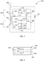
- FIG. 3 is a schematic diagram of an illustrative alternative embodiment control circuit 102' which includes capacitors 380 and 382.
- Capacitors 380 and 382 provide transient voltage suppression. Capacitor 380 and 382 are coupled across switches 150 and 160, respectively. Capacitors 380 and 382 increase the life of switches 150 and 160 by offsetting the inductive collapse of the coil windings, which substantially reduces arcing in switches 150 and 160 as the transient energy is dissipated. In some embodiments, capacitors 380 and 382 may be rated at 250 volts.
- capacitors 380 and 382 can be used independently and in other embodiments transient suppression diodes 176 can be used independently.
- the transient suppression diodes 176 can be used in combination with capacitors 380 and 382, as illustrated in control circuit 102' of FIG. 3 , for more effective transient voltage suppression.
- the transient suppression diodes (TSV) 176 limit the back electromotive force to a level that is not damaging to contacts and other components of the circuit.
- FIG. 4 is a schematic diagram illustrating wiring two single-pole, single-throw switches in a contactor 100 to function as a single-pole, double-throw switch.
- a conductor 402 is coupled to the single pole of both normally closed switch 410 and normally open switch 412. From the switch positions illustrated in FIG. 4 , when actuated, actuator 106 operates to simultaneously open switch 410 and close switch 412 thereby transferring a conduction path initially established between conductor 402 and conductor 404 through switch 410, to be from conductor 402 to conductor 406 through switch 412. In this manner, a pair of simultaneously operated single-pole, single-throw switches, one normally open and the other normally closed, can be used to imitate the operation of a single-pole, double-throw switch.
Landscapes
- Physics & Mathematics (AREA)
- Electromagnetism (AREA)
- Keying Circuit Devices (AREA)
Claims (12)
- Contacteur (100), comprenant :une pluralité de commutateurs (104) ;un premier circuit d'entrée (148, 146, 174, 120, 172) pour recevoir un signal d'entrée de mise sous tension ;un deuxième circuit d'entrée (130, 132, 134, 170, 120, 172) pour recevoir un signal d'entrée de déclenchement ;un actionneur mobile (106) couplé mécaniquement à des commutateurs dans la pluralité de commutateurs (104), l'actionneur (106) étant mobile entre une position déclenchée et une position opérationnelle lors de la réception d'un signal d'entrée de mise sous tension sur le premier circuit d'entrée (148, 146, 174, 120, 172), et mobile entre la position opérationnelle et la position déclenchée lors de la réception d'un signal d'entrée de déclenchement sur le deuxième circuit d'entrée (130, 132, 134, 170, 120, 172) ;une bobine (120) ayant des première et deuxième extrémités, l'actionneur mobile (106) s'étendant à travers la bobine (120) en tant que noyau, la bobine (120) étant apte à faire bouger l'actionneur (106) lorsque soit un signal d'entrée de mise sous tension est reçu par le premier circuit d'entrée (148, 146, 174, 120, 172), soit qu'un signal d'entrée de déclenchement est reçu par le deuxième circuit d'entrée (130, 132, 134, 170, 120, 172) ;des premier et deuxième commutateurs (150, 160) couplés à des première et deuxième extrémités respectives de la bobine (120) et configurés pour inverser la polarité de la bobine (120) lors de chaque occurrence où l'actionneur (106) est actionné,les premier et deuxième commutateurs (150, 160) étant commutables pour enlever les première et deuxième extrémités de la bobine sur le premier circuit d'entrée et pour coupler les première et deuxième extrémités de la bobine dans le deuxième circuit d'entrée en polarité opposée par rapport au premier circuit d'entrée afin d'inclure la bobine (120) dans le deuxième circuit d'entrée (130, 132, 134, 170, 120, 172) lorsque l'actionneur (106) est déplacé dans la position opérationnelle, dans lequel lorsque le signal d'entrée de déclenchement est reçu sur le deuxième circuit d'entrée (130, 132, 134, 170, 120, 172) la bobine (120) est excitée pour faire fonctionner l'actionneur (106) afin de le faire passer à la position déclenchée, etles premier et deuxième commutateurs (150, 160) étant commutables pour enlever les première et deuxième extrémités de la bobine sur le deuxième circuit d'entrée et pour coupler les première et deuxième extrémités de la bobine dans le premier circuit d'entrée en polarité opposée par rapport au deuxième circuit d'entrée afin d'inclure la bobine (120) dans le premier circuit d'entrée (148, 146, 174, 120, 172) lorsque l'actionneur (106) est déplacé dans la position déclenchée, dans lequel lorsque le signal d'entrée de mise sous tension est reçu sur le premier circuit d'entrée (148, 146, 174, 120, 172) la bobine (120) est excitée pour faire fonctionner l'actionneur (106) afin de le faire passer à la position opérationnelle ;dans lequel au fur et à mesure que l'actionneur (106) est actionné, l'actionneur opère les premier et deuxième commutateurs (150, 160) afin de changer l'état en préparation à l'excitation de la bobine (120) pour qu'elle soit polarisée magnétiquement dans une direction de polarisation opposée durant un actionnement suivant ultérieur.
- Contacteur (100) tel qu'énoncé dans la revendication 1, comprenant en outre un dispositif de suppression de tension transitoire (176) couplé entre les première et deuxième extrémités de la bobine (120), le dispositif de suppression de tension transitoire (176) étant destiné à réduire les tensions transitoires lorsque le courant passant à travers la bobine (120) est coupé abruptement.
- Contacteur (100) tel qu'énoncé dans la revendication 2, dans lequel le dispositif de suppression de tension transitoire (176) est un dispositif bidirectionnel.
- Contacteur (100) tel qu'énoncé dans la revendication 2, dans lequel le dispositif de suppression de tension transitoire (176) est sélectionné parmi le groupe consistant en une diode à avalanche au silicium ou une diode Zener.
- Contacteur (100) tel qu'énoncé dans la revendication 1, dans lequel les premier et deuxième commutateurs (150, 160) sont des commutateurs unipolaires bidirectionnels.
- Contacteur (100) tel qu'énoncé dans la revendication 5, comprenant en outre un condensateur (380, 382) couplé aux bornes d'au moins un des commutateurs unipolaires bidirectionnels (150, 160).
- Contacteur (100) tel qu'énoncé dans la revendication 1, dans lequel des points de fonctionnement de commutation des premier et deuxième commutateurs (150, 160) sont réglés de sorte que l'ouverture des premier et deuxième commutateurs ne se produise pas tant que l'actionneur ne s'est pas déplacé jusqu'à mi-chemin environ par rapport à la position d'actionneur finale du prochain état.
- Procédé permettant d'opérer un contacteur (100), le contacteur (100) ayant une pluralité de commutateurs (104) couplés mécaniquement à un actionneur (106) mobile dans des directions opposées entre une position déclenchée et une position opérationnelle afin de changer un état de la pluralité de commutateurs (104), l'actionneur mobile (106) s'étendant à travers une bobine (120) en tant que noyau, la bobine (120) étant apte à faire bouger l'actionneur (106) lors de son excitation, comprenant :le fait de recevoir un signal de mise sous tension sur un premier circuit d'entrée (148, 146, 174, 120, 172) ;le fait d'appliquer le signal de mise sous tension à la bobine (120) afin d'actionner l'actionneur (106) de telle sorte que l'actionneur (106) passe de la position déclenchée à la position opérationnelle, dans lequel la pluralité de commutateurs (104) passent à des états respectifs correspondant à la position opérationnelle ;lors de l'actionnement de l'actionneur (106) pour passer à la position opérationnelle, le fait d'opérer les premier et deuxième commutateurs (150, 160) pour commencer l'enlèvement des première et deuxième extrémités de la bobine (120) sur le premier circuit d'entrée (148, 146, 174, 120, 172) et pour coupler les première et deuxième extrémités de la bobine (120) dans un deuxième circuit d'entrée (130, 132, 134, 170, 120, 172) dans une polarité opposée par rapport au premier circuit d'entrée en préparation à l'excitation de la bobine (120) pour qu'elle soit polarisée magnétiquement dans une direction de polarisation opposée durant un actionnement suivant ultérieur ;lors de l'actionnement de l'actionneur (106) pour passer à la position déclenchée, le fait d'opérer les premier et deuxième commutateurs (150, 160) pour commencer l'enlèvement des première et deuxième extrémités de la bobine (120) sur le deuxième circuit d'entrée (148, 146, 174, 120, 172) et pour coupler les première et deuxième extrémités de la bobine (120) dans un premier circuit d'entrée (130, 132, 134, 170, 120, 172) dans une polarité opposée par rapport au deuxième circuit d'entrée en préparation à l'excitation de la bobine (120) pour qu'elle soit polarisée magnétiquement dans une direction de polarisation opposée durant un actionnement suivant ultérieur ; etau fur et à mesure que l'actionneur est actionné, l'actionneur opère les premier et deuxième commutateurs couplés aux première et deuxième extrémités respective de la bobine pour inverser la polarité de la bobine lors de chaque occurrence où l'actionneur est actionné.
- Procédé permettant d'opérer un contacteur (100), tel qu'énoncé dans la revendication 8, comprenant en outre :le fait de recevoir un signal de déclenchement sur le deuxième circuit d'entrée (130, 132, 134, 170, 120, 172) ;le fait d'appliquer le signal de déclenchement à la bobine (120) afin d'actionner l'actionneur (106) de telle sorte que l'actionneur (106) passe de la position opérationnelle à la position déclenchée, dans lequel la pluralité de commutateurs (104) passent à des états respectifs correspondant à la position déclenchée.
- Procédé permettant d'opérer un contacteur (100), tel qu'énoncé dans la revendication 8, comprenant en outre :
le fait de fournir une suppression de tension aux bornes de la bobine (120) afin d'atténuer les tensions transitoires causées par l'interruption de courant passant à travers la bobine (120). - Procédé permettant d'opérer un contacteur (100), tel qu'énoncé dans la revendication 9, dans lequel le fait de commencer l'enlèvement des première et deuxième extrémités de la bobine (120) sur le deuxième circuit d'entrée (130, 132, 134, 170, 120, 172) comprend le fait de prédéfinir un point de fonctionnement d'au moins un commutateur (150 ou 160) .
- Procédé permettant d'opérer un contacteur (100), tel qu'énoncé dans la revendication 9, comprenant en outre :
le fait de supprimer les formations d'arc (76, 380, 382) lorsque les première et deuxième extrémités de la bobine (120) sont enlevées du premier circuit d'entrée (148, 146, 174, 120, 172) et couplées au deuxième circuit d'entrée (130, 132, 134, 170, 120, 172) ou lorsqu'elles sont enlevées du deuxième circuit d'entrée (130, 132, 134, 170, 120, 172) et couplées au premier circuit d'entrée (148, 146, 174, 120, 172).
Applications Claiming Priority (2)
| Application Number | Priority Date | Filing Date | Title |
|---|---|---|---|
| US15/365,020 US10366854B2 (en) | 2016-11-30 | 2016-11-30 | Contactor with coil polarity reversing control circuit |
| PCT/IB2017/057448 WO2018100490A1 (fr) | 2016-11-30 | 2017-11-28 | Contacteur avec circuit de commande d'inversion de polarité de bobine |
Publications (2)
| Publication Number | Publication Date |
|---|---|
| EP3549149A1 EP3549149A1 (fr) | 2019-10-09 |
| EP3549149B1 true EP3549149B1 (fr) | 2023-10-11 |
Family
ID=60702890
Family Applications (1)
| Application Number | Title | Priority Date | Filing Date |
|---|---|---|---|
| EP17817151.8A Active EP3549149B1 (fr) | 2016-11-30 | 2017-11-28 | Contacteur avec circuit de commande d'inversion de polarité de bobine |
Country Status (5)
| Country | Link |
|---|---|
| US (1) | US10366854B2 (fr) |
| EP (1) | EP3549149B1 (fr) |
| JP (1) | JP2019537220A (fr) |
| CN (1) | CN110024071A (fr) |
| WO (1) | WO2018100490A1 (fr) |
Families Citing this family (5)
| Publication number | Priority date | Publication date | Assignee | Title |
|---|---|---|---|---|
| US20190273393A1 (en) * | 2018-03-03 | 2019-09-05 | Chengwu Chen | Energy management system, method and device for maximizing power utilization from alterative electrical power sources |
| US11462345B2 (en) * | 2019-09-30 | 2022-10-04 | Rockwell Automation Technologies, Inc. | Systems and methods for controlling contactor bounce |
| US11676786B2 (en) * | 2020-04-09 | 2023-06-13 | Rockwell Automation Technologies, Inc. | Systems and methods for controlling contactor open time |
| US11521815B2 (en) * | 2020-07-15 | 2022-12-06 | Rockwell Automation Technologies, Inc. | Detecting a position of an armature in an electromagnetic actuator |
| CN113371018B (zh) * | 2021-06-25 | 2025-07-29 | 山东朗进科技股份有限公司 | 一种高速动车座椅转向装置及控制电路 |
Family Cites Families (19)
| Publication number | Priority date | Publication date | Assignee | Title |
|---|---|---|---|---|
| US4176388A (en) | 1978-03-30 | 1979-11-27 | Towmotor Corporation | Control circuit for a contactor |
| JPS57151121A (en) * | 1981-03-14 | 1982-09-18 | Tokyo Shibaura Electric Co | Hybrid switching device |
| US4682801A (en) * | 1984-08-31 | 1987-07-28 | Securitron-Magnalock Corp. | Electromagnet access control circuit |
| FR2631717B1 (fr) | 1988-05-20 | 1990-09-07 | Telemecanique Electrique | Systeme et dispositif de commande pour appareil contacteur |
| JPH02110150U (fr) * | 1989-02-21 | 1990-09-04 | ||
| US5241290A (en) * | 1991-12-20 | 1993-08-31 | Square D Company | Compact circuit breaker |
| GB9911162D0 (en) | 1999-05-14 | 1999-07-14 | Danor Electronics | Contactors |
| US6507255B1 (en) * | 2000-11-08 | 2003-01-14 | Eaton Corporation | Remotely controllable circuit breaker |
| US6794968B2 (en) | 2002-05-09 | 2004-09-21 | Contact Industries, Inc. | Magnetic latching contactor |
| US6837729B2 (en) | 2002-09-10 | 2005-01-04 | Tyco Electronics Corporation | High power electrical contactor with improved bridge contact mechanism |
| US20050035667A1 (en) * | 2003-07-23 | 2005-02-17 | Constantinos Joannou | Multipole switch and automatic polarity adjusting switching system |
| DE102004015932A1 (de) * | 2004-04-01 | 2005-10-20 | Moeller Gmbh | Verfahren und Schaltungsanordnung zum Betreiben eines Magnetantriebes |
| US7542250B2 (en) * | 2007-01-10 | 2009-06-02 | General Electric Company | Micro-electromechanical system based electric motor starter |
| JP5606304B2 (ja) * | 2010-12-17 | 2014-10-15 | 三菱電機株式会社 | 開閉装置の電磁操作装置及び駆動回路 |
| DE102011056577C5 (de) | 2011-12-19 | 2015-02-19 | Sma Solar Technology Ag | Schaltungsanordnung zur Unterdrückung eines bei einem Schaltvorgang auftretenden Lichtbogens |
| JP6106528B2 (ja) | 2013-06-05 | 2017-04-05 | 株式会社日立産機システム | コンタクタ用操作装置 |
| GB2520572A (en) * | 2013-11-26 | 2015-05-27 | Johnson Electric Sa | Electrical Contactor |
| EP2983187B1 (fr) | 2014-08-05 | 2017-05-31 | Tyco Electronics (Shanghai) Co. Ltd. | Contacteur, ensemble contacteur et circuit de commande |
| US9373468B2 (en) | 2014-09-16 | 2016-06-21 | Tyco Electronics Corporation | Arc control for contactor assembly |
-
2016
- 2016-11-30 US US15/365,020 patent/US10366854B2/en active Active
-
2017
- 2017-11-28 EP EP17817151.8A patent/EP3549149B1/fr active Active
- 2017-11-28 JP JP2019528039A patent/JP2019537220A/ja active Pending
- 2017-11-28 CN CN201780074209.4A patent/CN110024071A/zh active Pending
- 2017-11-28 WO PCT/IB2017/057448 patent/WO2018100490A1/fr not_active Ceased
Also Published As
| Publication number | Publication date |
|---|---|
| US10366854B2 (en) | 2019-07-30 |
| US20180151321A1 (en) | 2018-05-31 |
| WO2018100490A1 (fr) | 2018-06-07 |
| JP2019537220A (ja) | 2019-12-19 |
| CN110024071A (zh) | 2019-07-16 |
| EP3549149A1 (fr) | 2019-10-09 |
Similar Documents
| Publication | Publication Date | Title |
|---|---|---|
| EP3549149B1 (fr) | Contacteur avec circuit de commande d'inversion de polarité de bobine | |
| KR101483298B1 (ko) | 모터 시동기 | |
| TWI343068B (fr) | ||
| EP1975960A1 (fr) | Actionneur bistable magnétique, circuit de commande électronique et procédé pour faire fonctionner cet actionneur | |
| WO2007011692A1 (fr) | Dispositif et procédé d’élimination d’arc de contact de relais | |
| EP3893259B1 (fr) | Systèmes et procédés de commande du temps d'ouverture d'un contacteur | |
| JP6252448B2 (ja) | 開閉器および電力変換装置 | |
| KR20160147181A (ko) | 영구자석형 전자접촉기를 구비한 전동기 제어반 | |
| US10395870B2 (en) | Relay with first and second electromagnets for placing and keeping a contact in a closed state | |
| JP2006236773A (ja) | 遮断器 | |
| CN118571672A (zh) | 用于控制开关装置的控制设备 | |
| US7352265B2 (en) | Manual trip control method and arrangement for multiple circuit interrupters | |
| KR20160143141A (ko) | 고속 스위치 | |
| WO2025119930A1 (fr) | Dispositif de commutation électromagnétique bistable | |
| JP6012813B2 (ja) | 開閉装置用電磁操作装置 | |
| SU1231541A1 (ru) | Устройство дл управлени быстродействующим выключателем посто нного тока | |
| JP4592365B2 (ja) | 真空遮断装置の制御回路 | |
| JP2025021770A (ja) | 電流開閉装置 | |
| Klimenko | The control of polarized bistable electromagnetic actuators of medium voltage vacuum circuit breakers | |
| JP2025011032A (ja) | 電気機械デバイスを駆動するためのドライバ | |
| CN114097054A (zh) | 断路器 | |
| KR101640145B1 (ko) | 순간정전 방지 및 저전압 방지 기능이 내장된 전자 접촉기 | |
| RU1793488C (ru) | Устройство дл гибридной коммутации электрической цепи | |
| EP1821400A1 (fr) | Dispositif pour mettre à disposition un courant triphasé pour un moteur électrique |
Legal Events
| Date | Code | Title | Description |
|---|---|---|---|
| STAA | Information on the status of an ep patent application or granted ep patent |
Free format text: STATUS: UNKNOWN |
|
| STAA | Information on the status of an ep patent application or granted ep patent |
Free format text: STATUS: THE INTERNATIONAL PUBLICATION HAS BEEN MADE |
|
| PUAI | Public reference made under article 153(3) epc to a published international application that has entered the european phase |
Free format text: ORIGINAL CODE: 0009012 |
|
| STAA | Information on the status of an ep patent application or granted ep patent |
Free format text: STATUS: REQUEST FOR EXAMINATION WAS MADE |
|
| 17P | Request for examination filed |
Effective date: 20190624 |
|
| AK | Designated contracting states |
Kind code of ref document: A1 Designated state(s): AL AT BE BG CH CY CZ DE DK EE ES FI FR GB GR HR HU IE IS IT LI LT LU LV MC MK MT NL NO PL PT RO RS SE SI SK SM TR |
|
| AX | Request for extension of the european patent |
Extension state: BA ME |
|
| DAV | Request for validation of the european patent (deleted) | ||
| DAX | Request for extension of the european patent (deleted) | ||
| STAA | Information on the status of an ep patent application or granted ep patent |
Free format text: STATUS: EXAMINATION IS IN PROGRESS |
|
| 17Q | First examination report despatched |
Effective date: 20210622 |
|
| GRAP | Despatch of communication of intention to grant a patent |
Free format text: ORIGINAL CODE: EPIDOSNIGR1 |
|
| STAA | Information on the status of an ep patent application or granted ep patent |
Free format text: STATUS: GRANT OF PATENT IS INTENDED |
|
| INTG | Intention to grant announced |
Effective date: 20230510 |
|
| GRAS | Grant fee paid |
Free format text: ORIGINAL CODE: EPIDOSNIGR3 |
|
| GRAA | (expected) grant |
Free format text: ORIGINAL CODE: 0009210 |
|
| STAA | Information on the status of an ep patent application or granted ep patent |
Free format text: STATUS: THE PATENT HAS BEEN GRANTED |
|
| RAP1 | Party data changed (applicant data changed or rights of an application transferred) |
Owner name: TE CONNECTIVITY SOLUTIONS GMBH |
|
| AK | Designated contracting states |
Kind code of ref document: B1 Designated state(s): AL AT BE BG CH CY CZ DE DK EE ES FI FR GB GR HR HU IE IS IT LI LT LU LV MC MK MT NL NO PL PT RO RS SE SI SK SM TR |
|
| REG | Reference to a national code |
Ref country code: GB Ref legal event code: FG4D |
|
| REG | Reference to a national code |
Ref country code: CH Ref legal event code: EP |
|
| REG | Reference to a national code |
Ref country code: DE Ref legal event code: R096 Ref document number: 602017075271 Country of ref document: DE |
|
| REG | Reference to a national code |
Ref country code: IE Ref legal event code: FG4D |
|
| REG | Reference to a national code |
Ref country code: LT Ref legal event code: MG9D |
|
| REG | Reference to a national code |
Ref country code: NL Ref legal event code: MP Effective date: 20231011 |
|
| REG | Reference to a national code |
Ref country code: AT Ref legal event code: MK05 Ref document number: 1621090 Country of ref document: AT Kind code of ref document: T Effective date: 20231011 |
|
| PG25 | Lapsed in a contracting state [announced via postgrant information from national office to epo] |
Ref country code: NL Free format text: LAPSE BECAUSE OF FAILURE TO SUBMIT A TRANSLATION OF THE DESCRIPTION OR TO PAY THE FEE WITHIN THE PRESCRIBED TIME-LIMIT Effective date: 20231011 |
|
| PG25 | Lapsed in a contracting state [announced via postgrant information from national office to epo] |
Ref country code: GR Free format text: LAPSE BECAUSE OF FAILURE TO SUBMIT A TRANSLATION OF THE DESCRIPTION OR TO PAY THE FEE WITHIN THE PRESCRIBED TIME-LIMIT Effective date: 20240112 |
|
| PG25 | Lapsed in a contracting state [announced via postgrant information from national office to epo] |
Ref country code: IS Free format text: LAPSE BECAUSE OF FAILURE TO SUBMIT A TRANSLATION OF THE DESCRIPTION OR TO PAY THE FEE WITHIN THE PRESCRIBED TIME-LIMIT Effective date: 20240211 |
|
| PG25 | Lapsed in a contracting state [announced via postgrant information from national office to epo] |
Ref country code: LT Free format text: LAPSE BECAUSE OF FAILURE TO SUBMIT A TRANSLATION OF THE DESCRIPTION OR TO PAY THE FEE WITHIN THE PRESCRIBED TIME-LIMIT Effective date: 20231011 |
|
| PG25 | Lapsed in a contracting state [announced via postgrant information from national office to epo] |
Ref country code: AT Free format text: LAPSE BECAUSE OF FAILURE TO SUBMIT A TRANSLATION OF THE DESCRIPTION OR TO PAY THE FEE WITHIN THE PRESCRIBED TIME-LIMIT Effective date: 20231011 |
|
| PG25 | Lapsed in a contracting state [announced via postgrant information from national office to epo] |
Ref country code: ES Free format text: LAPSE BECAUSE OF FAILURE TO SUBMIT A TRANSLATION OF THE DESCRIPTION OR TO PAY THE FEE WITHIN THE PRESCRIBED TIME-LIMIT Effective date: 20231011 |
|
| PG25 | Lapsed in a contracting state [announced via postgrant information from national office to epo] |
Ref country code: LT Free format text: LAPSE BECAUSE OF FAILURE TO SUBMIT A TRANSLATION OF THE DESCRIPTION OR TO PAY THE FEE WITHIN THE PRESCRIBED TIME-LIMIT Effective date: 20231011 Ref country code: IS Free format text: LAPSE BECAUSE OF FAILURE TO SUBMIT A TRANSLATION OF THE DESCRIPTION OR TO PAY THE FEE WITHIN THE PRESCRIBED TIME-LIMIT Effective date: 20240211 Ref country code: GR Free format text: LAPSE BECAUSE OF FAILURE TO SUBMIT A TRANSLATION OF THE DESCRIPTION OR TO PAY THE FEE WITHIN THE PRESCRIBED TIME-LIMIT Effective date: 20240112 Ref country code: ES Free format text: LAPSE BECAUSE OF FAILURE TO SUBMIT A TRANSLATION OF THE DESCRIPTION OR TO PAY THE FEE WITHIN THE PRESCRIBED TIME-LIMIT Effective date: 20231011 Ref country code: BG Free format text: LAPSE BECAUSE OF FAILURE TO SUBMIT A TRANSLATION OF THE DESCRIPTION OR TO PAY THE FEE WITHIN THE PRESCRIBED TIME-LIMIT Effective date: 20240111 Ref country code: AT Free format text: LAPSE BECAUSE OF FAILURE TO SUBMIT A TRANSLATION OF THE DESCRIPTION OR TO PAY THE FEE WITHIN THE PRESCRIBED TIME-LIMIT Effective date: 20231011 Ref country code: PT Free format text: LAPSE BECAUSE OF FAILURE TO SUBMIT A TRANSLATION OF THE DESCRIPTION OR TO PAY THE FEE WITHIN THE PRESCRIBED TIME-LIMIT Effective date: 20240212 |
|
| PG25 | Lapsed in a contracting state [announced via postgrant information from national office to epo] |
Ref country code: SE Free format text: LAPSE BECAUSE OF FAILURE TO SUBMIT A TRANSLATION OF THE DESCRIPTION OR TO PAY THE FEE WITHIN THE PRESCRIBED TIME-LIMIT Effective date: 20231011 Ref country code: RS Free format text: LAPSE BECAUSE OF FAILURE TO SUBMIT A TRANSLATION OF THE DESCRIPTION OR TO PAY THE FEE WITHIN THE PRESCRIBED TIME-LIMIT Effective date: 20231011 Ref country code: PL Free format text: LAPSE BECAUSE OF FAILURE TO SUBMIT A TRANSLATION OF THE DESCRIPTION OR TO PAY THE FEE WITHIN THE PRESCRIBED TIME-LIMIT Effective date: 20231011 Ref country code: NO Free format text: LAPSE BECAUSE OF FAILURE TO SUBMIT A TRANSLATION OF THE DESCRIPTION OR TO PAY THE FEE WITHIN THE PRESCRIBED TIME-LIMIT Effective date: 20240111 Ref country code: LV Free format text: LAPSE BECAUSE OF FAILURE TO SUBMIT A TRANSLATION OF THE DESCRIPTION OR TO PAY THE FEE WITHIN THE PRESCRIBED TIME-LIMIT Effective date: 20231011 Ref country code: HR Free format text: LAPSE BECAUSE OF FAILURE TO SUBMIT A TRANSLATION OF THE DESCRIPTION OR TO PAY THE FEE WITHIN THE PRESCRIBED TIME-LIMIT Effective date: 20231011 |
|
| REG | Reference to a national code |
Ref country code: CH Ref legal event code: PL |
|
| PG25 | Lapsed in a contracting state [announced via postgrant information from national office to epo] |
Ref country code: DK Free format text: LAPSE BECAUSE OF FAILURE TO SUBMIT A TRANSLATION OF THE DESCRIPTION OR TO PAY THE FEE WITHIN THE PRESCRIBED TIME-LIMIT Effective date: 20231011 |
|
| REG | Reference to a national code |
Ref country code: DE Ref legal event code: R097 Ref document number: 602017075271 Country of ref document: DE |
|
| PG25 | Lapsed in a contracting state [announced via postgrant information from national office to epo] |
Ref country code: LU Free format text: LAPSE BECAUSE OF NON-PAYMENT OF DUE FEES Effective date: 20231128 |
|
| PG25 | Lapsed in a contracting state [announced via postgrant information from national office to epo] |
Ref country code: CH Free format text: LAPSE BECAUSE OF NON-PAYMENT OF DUE FEES Effective date: 20231130 |
|
| PG25 | Lapsed in a contracting state [announced via postgrant information from national office to epo] |
Ref country code: CZ Free format text: LAPSE BECAUSE OF FAILURE TO SUBMIT A TRANSLATION OF THE DESCRIPTION OR TO PAY THE FEE WITHIN THE PRESCRIBED TIME-LIMIT Effective date: 20231011 |
|
| PG25 | Lapsed in a contracting state [announced via postgrant information from national office to epo] |
Ref country code: SK Free format text: LAPSE BECAUSE OF FAILURE TO SUBMIT A TRANSLATION OF THE DESCRIPTION OR TO PAY THE FEE WITHIN THE PRESCRIBED TIME-LIMIT Effective date: 20231011 |
|
| PG25 | Lapsed in a contracting state [announced via postgrant information from national office to epo] |
Ref country code: SM Free format text: LAPSE BECAUSE OF FAILURE TO SUBMIT A TRANSLATION OF THE DESCRIPTION OR TO PAY THE FEE WITHIN THE PRESCRIBED TIME-LIMIT Effective date: 20231011 Ref country code: SK Free format text: LAPSE BECAUSE OF FAILURE TO SUBMIT A TRANSLATION OF THE DESCRIPTION OR TO PAY THE FEE WITHIN THE PRESCRIBED TIME-LIMIT Effective date: 20231011 Ref country code: RO Free format text: LAPSE BECAUSE OF FAILURE TO SUBMIT A TRANSLATION OF THE DESCRIPTION OR TO PAY THE FEE WITHIN THE PRESCRIBED TIME-LIMIT Effective date: 20231011 Ref country code: LU Free format text: LAPSE BECAUSE OF NON-PAYMENT OF DUE FEES Effective date: 20231128 Ref country code: IT Free format text: LAPSE BECAUSE OF FAILURE TO SUBMIT A TRANSLATION OF THE DESCRIPTION OR TO PAY THE FEE WITHIN THE PRESCRIBED TIME-LIMIT Effective date: 20231011 Ref country code: EE Free format text: LAPSE BECAUSE OF FAILURE TO SUBMIT A TRANSLATION OF THE DESCRIPTION OR TO PAY THE FEE WITHIN THE PRESCRIBED TIME-LIMIT Effective date: 20231011 Ref country code: DK Free format text: LAPSE BECAUSE OF FAILURE TO SUBMIT A TRANSLATION OF THE DESCRIPTION OR TO PAY THE FEE WITHIN THE PRESCRIBED TIME-LIMIT Effective date: 20231011 Ref country code: CZ Free format text: LAPSE BECAUSE OF FAILURE TO SUBMIT A TRANSLATION OF THE DESCRIPTION OR TO PAY THE FEE WITHIN THE PRESCRIBED TIME-LIMIT Effective date: 20231011 Ref country code: CH Free format text: LAPSE BECAUSE OF NON-PAYMENT OF DUE FEES Effective date: 20231130 |
|
| REG | Reference to a national code |
Ref country code: BE Ref legal event code: MM Effective date: 20231130 |
|
| PLBE | No opposition filed within time limit |
Free format text: ORIGINAL CODE: 0009261 |
|
| STAA | Information on the status of an ep patent application or granted ep patent |
Free format text: STATUS: NO OPPOSITION FILED WITHIN TIME LIMIT |
|
| PG25 | Lapsed in a contracting state [announced via postgrant information from national office to epo] |
Ref country code: MC Free format text: LAPSE BECAUSE OF FAILURE TO SUBMIT A TRANSLATION OF THE DESCRIPTION OR TO PAY THE FEE WITHIN THE PRESCRIBED TIME-LIMIT Effective date: 20231011 |
|
| PG25 | Lapsed in a contracting state [announced via postgrant information from national office to epo] |
Ref country code: MC Free format text: LAPSE BECAUSE OF FAILURE TO SUBMIT A TRANSLATION OF THE DESCRIPTION OR TO PAY THE FEE WITHIN THE PRESCRIBED TIME-LIMIT Effective date: 20231011 |
|
| REG | Reference to a national code |
Ref country code: IE Ref legal event code: MM4A |
|
| 26N | No opposition filed |
Effective date: 20240712 |
|
| PG25 | Lapsed in a contracting state [announced via postgrant information from national office to epo] |
Ref country code: IE Free format text: LAPSE BECAUSE OF NON-PAYMENT OF DUE FEES Effective date: 20231128 |
|
| PG25 | Lapsed in a contracting state [announced via postgrant information from national office to epo] |
Ref country code: BE Free format text: LAPSE BECAUSE OF NON-PAYMENT OF DUE FEES Effective date: 20231130 |
|
| PG25 | Lapsed in a contracting state [announced via postgrant information from national office to epo] |
Ref country code: SI Free format text: LAPSE BECAUSE OF FAILURE TO SUBMIT A TRANSLATION OF THE DESCRIPTION OR TO PAY THE FEE WITHIN THE PRESCRIBED TIME-LIMIT Effective date: 20231011 |
|
| PG25 | Lapsed in a contracting state [announced via postgrant information from national office to epo] |
Ref country code: SI Free format text: LAPSE BECAUSE OF FAILURE TO SUBMIT A TRANSLATION OF THE DESCRIPTION OR TO PAY THE FEE WITHIN THE PRESCRIBED TIME-LIMIT Effective date: 20231011 Ref country code: IE Free format text: LAPSE BECAUSE OF NON-PAYMENT OF DUE FEES Effective date: 20231128 Ref country code: BE Free format text: LAPSE BECAUSE OF NON-PAYMENT OF DUE FEES Effective date: 20231130 |
|
| PG25 | Lapsed in a contracting state [announced via postgrant information from national office to epo] |
Ref country code: FI Free format text: LAPSE BECAUSE OF FAILURE TO SUBMIT A TRANSLATION OF THE DESCRIPTION OR TO PAY THE FEE WITHIN THE PRESCRIBED TIME-LIMIT Effective date: 20231011 |
|
| PG25 | Lapsed in a contracting state [announced via postgrant information from national office to epo] |
Ref country code: CY Free format text: LAPSE BECAUSE OF FAILURE TO SUBMIT A TRANSLATION OF THE DESCRIPTION OR TO PAY THE FEE WITHIN THE PRESCRIBED TIME-LIMIT; INVALID AB INITIO Effective date: 20171128 |
|
| PG25 | Lapsed in a contracting state [announced via postgrant information from national office to epo] |
Ref country code: HU Free format text: LAPSE BECAUSE OF FAILURE TO SUBMIT A TRANSLATION OF THE DESCRIPTION OR TO PAY THE FEE WITHIN THE PRESCRIBED TIME-LIMIT; INVALID AB INITIO Effective date: 20171128 |
|
| PGFP | Annual fee paid to national office [announced via postgrant information from national office to epo] |
Ref country code: FR Payment date: 20250930 Year of fee payment: 9 |
|
| PG25 | Lapsed in a contracting state [announced via postgrant information from national office to epo] |
Ref country code: TR Free format text: LAPSE BECAUSE OF FAILURE TO SUBMIT A TRANSLATION OF THE DESCRIPTION OR TO PAY THE FEE WITHIN THE PRESCRIBED TIME-LIMIT Effective date: 20231011 |
|
| PGFP | Annual fee paid to national office [announced via postgrant information from national office to epo] |
Ref country code: DE Payment date: 20250930 Year of fee payment: 9 |
|
| PGFP | Annual fee paid to national office [announced via postgrant information from national office to epo] |
Ref country code: GB Payment date: 20251001 Year of fee payment: 9 |