EP3549223B1 - Contrôleur de puissance interphasé - Google Patents
Contrôleur de puissance interphasé Download PDFInfo
- Publication number
- EP3549223B1 EP3549223B1 EP16806031.7A EP16806031A EP3549223B1 EP 3549223 B1 EP3549223 B1 EP 3549223B1 EP 16806031 A EP16806031 A EP 16806031A EP 3549223 B1 EP3549223 B1 EP 3549223B1
- Authority
- EP
- European Patent Office
- Prior art keywords
- connection point
- line connection
- phase line
- side phase
- ipc
- Prior art date
- Legal status (The legal status is an assumption and is not a legal conclusion. Google has not performed a legal analysis and makes no representation as to the accuracy of the status listed.)
- Active
Links
Images




Classifications
-
- H—ELECTRICITY
- H02—GENERATION; CONVERSION OR DISTRIBUTION OF ELECTRIC POWER
- H02J—ELECTRIC POWER NETWORKS; CIRCUIT ARRANGEMENTS OR SYSTEMS FOR SUPPLYING OR DISTRIBUTING ELECTRIC POWER; SYSTEMS FOR STORING ELECTRIC ENERGY
- H02J3/00—Circuit arrangements for AC mains or AC distribution networks
- H02J3/04—Arrangements for connecting networks of the same frequency but supplied from different sources
- H02J3/06—Controlling the transfer of power between connected networks; Controlling load sharing between connected networks
-
- H—ELECTRICITY
- H02—GENERATION; CONVERSION OR DISTRIBUTION OF ELECTRIC POWER
- H02H—EMERGENCY PROTECTIVE CIRCUIT ARRANGEMENTS
- H02H7/00—Emergency protective circuit arrangements specially adapted for specific types of electric machines or apparatus or for sectionalised protection of cable or line systems, and effecting automatic switching in the event of an undesired change from normal working conditions
- H02H7/26—Sectionalised protection of cable or line systems, e.g. for disconnecting a section on which a short-circuit, earth fault, or arc discharge has occured
- H02H7/28—Sectionalised protection of cable or line systems, e.g. for disconnecting a section on which a short-circuit, earth fault, or arc discharge has occured for meshed systems
Definitions
- the invention relates to an interphase power controller device and a method thereof.
- Highly meshed electrical networks offer several paths to passing power flows. Many intrinsic physical variables that define an electrical network make power flows difficult to predict. Unexpected problems such as loop flows, leading to congestions, or unequal loading of parallel lines, leading to poor utilization of the installed capacity, may appear.
- a Phase Shifting Transformer (PST) is a solution to such problems.
- Another issue with highly meshed electrical networks is the increase in available fault current that comes with each new interconnection. To ensure that installed protection equipment will survive a system fault, the fault current level must not be too high. Exceeding for instance the rated breaking current of the circuit breakers may result in breakdown through thermal instability or from first half cycle magnetic forces.
- ENTSO-E European Network of Transmission System Operators for Electricity
- Direct interconnection of the sub-transmission networks can however be inappropriate due to network conditions such as poorly balanced parallel circuits or differences in sub-transmission network load/generation. In these cases the interconnection, or some other part of the network, may experience an overload during steady state operation or during contingencies.
- IPC interphase power controller
- Electrical networks commonly comprises transmission networks and sub-transmission networks, the latter of which having lower system voltage level.
- An IPC can be arranged between send point S and receive point R.
- Interconnecting these sub-transmission networks A and B is desirable since the transmission capacity of the transmission network is increased, the reliability of the transmission network is increased, and voltage levels may be improved.
- WO 94/17579 A1 discloses an interphase power controller for interconnecting first and second synchronous polyphase AC networks.
- IPC interphase power controller
- an interphase power controller (IPC) device comprises a first side phase line connection point a, a first side phase line connection point b and a first side phase line connection point c, a second side phase line connection point a, a second side phase line connection point b and a second side phase line connection point c, a first inductor connecting the first side phase line connection point a to the second side phase line connection point b, and a first capacitor connecting the first side phase line connection point a to the second side phase line connection point c, a second inductor connecting the first side phase line connection point b to the second side phase line connection point c, and a second capacitor connecting the first side phase line connection point b to the second side phase line connection point a, a third inductor connecting the first side phase line connection point c to the second side phase line connection point a, and a third capacitor connecting the first side phase line connection point c to the second side phase line connection point b, a first side phase line connection point c to the second side phase line connection point
- the IPC device may be a passive IPC device.
- the first to third varistors may have a rated voltage for series resonance energy dissipation of open circuits on one side of the IPC.
- the first to third varistors may alternatively have a rated voltage for series resonance energy dissipation of open circuits on both sides of the IPC.
- the first to third inductor may each have the same impedance value, and the first to third capacitor may each have a conjugate value thereof.
- a method for interphase power control comprises connecting a first side phase line connection point a to a second side phase line connection point b through a first inductor, connecting the first side phase line connection point a to a second side phase line connection point c through a first capacitor, connecting a first side phase line connection point b to the second side phase line connection point c through a second inductor, connecting the first side phase line connection point b to a second side phase line connection point a through a second capacitor, connecting a first side phase line connection point c to the second side phase line connection point a through a third inductor, connecting the first side phase line connection point c to the second side phase line connection point b through a third capacitor, connecting the first side phase line connection point a to the second side phase line connection point a through a first varistor, connecting the first side phase line connection point b to the second side phase line connection point b through a second varistor, and connecting the first side phase line connection point c to the
- the IPC device may be a passive IPC device.
- the method may further comprise providing energy dissipation of an open circuit on one side of the IPC by series resonance through the first to third varistors.
- the method may further comprise providing energy dissipation of an open circuit on both sides of the IPC by series resonance through the first to third varistors.
- the first to third inductor may each have the same impedance value, and the first to third capacitor each have a conjugate value thereof.
- An interphase power controller (IPC) device as described in US patent 5,642,005 , comprises conjugated reactive elements.
- Resulting voltage rise across the reactive elements is therein prevented using varistors connected to ground. With the voltage rise, caused by the series resonance circuit, the varistors start to conduct and disrupts the resonance. This is one of the major dimensioning fault cases for the IPC.
- a device for interconnection of sub-transmission networks is presented herein.
- the device ideally maintains a specified flow of active power regardless of network voltage angles at its connection points. Thereby, the flow of active power is no longer dictated by the inherent voltage angle difference between the sub-transmission networks and interconnections can be made regardless of possible inappropriate network conditions.
- the device may either be connected all the time or bypassed when the natural power flow through the interconnection is preferred.
- an IPC device is used to interconnect the sub-transmission networks, several benefits may be achieved. For instance, with reference to Fig. 1 , during periods of high generation and low load in a sub-transmission network B, the interconnection can be used to reroute power through the IPC via a sub-transmission network A to the transmission network. Thereby potential overloads in sub-transmission network B's connection to the transmission network are alleviated and the capacity is thus increased.
- An increase in reliability obtained by use of an IPC device to interconnect sub-transmission networks A and B is enlightened through the following example. Transfer capacity between bus B2 and the transmission network is reduced due to a breakdown of either of the connections in sub-transmission network B in Fig. 1 . As the interconnection with network A is normally forced to be left open, having an interconnecting device increases the reliability. Interconnection between the sub-transmission networks is possible as the IPC device ideally maintains a pre-specified power flow through the interconnection during contingencies.
- PFC power flow controller
- the present invention is thus advantageous when the cost for reinforcements are high, when reinforcements are not possible, when protection equipment upgrades are costly, and/or when the controllability benefits of a conventional PFC does not supersede the relative cost increase.
- a passive IPC device means that the device is built based on passive electronic components such as inductors and capacitors.
- the presented device will have one further benefit compared to some conventional PFCs, e.g. the PST. Since the presented IPC device ideally maintains a specified power throughput, regardless of the angle difference across it, an operator can be confident of the impact the IPC device will have once connected. This also holds for contingency situations. Other PFCs may have several settings leading to various, voltage angle dependent, power throughputs as the network conditions are altered by the perturbation.
- the presented IPC device ideally maintains a constant power throughput, for a wide range of voltage angles across it, preferably in a passive manner. If needed, alterations can be performed to reverse, or alter the amount of, power throughput.
- a two-branch passive topology of an IPC allows for reliable power throughput using two phase shifts and two reactive elements per phase.
- the phase shifts can be accomplished passively using fixed ratio transformers or, in one of the simplest topologies, the adjacent phases on one side.
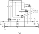
- the latter version of an IPC device, comprising only two components per phase, is called IPC240, and its full schematic is shown in Fig. 2 .
- the IPC240 device has a sending side (S) and a receiving side (R) for three phases a, b and c.
- the IPC240 device has sending side circuit breakers S-S, bypass breakers BP-S, and reactive breakers XL-S and XC-S.
- An IPC240 is an interphase power controller using two 120° phase shifted voltages.
- An IPC device with a reduced number of circuit breakers compared to the embodiment of the IPC240 illustrated in Fig. 2 , is desirable and possible with the IPC device presented herein. By reducing the number of circuit breakers, a reduced cost with maintained reliability is achieved.
- the indices of six voltages (V RC , V SA , V RB , V SC , V RA , V SB ) connected at either corner correspond to the a, b, and c phases of the sending end S and receiving end R. With this set of connections, the active power throughput would be positive from S to R.
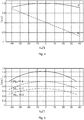
- Fig. 4 illustrates power characteristics, in per unit (p.u.), of IPC240 as functions of angle across device, wherein the relation between the angle across the IPC240, the active power throughput, and the reactive power contribution is illustrated.
- ⁇ SR ⁇ S - ⁇ R
- the active power throughput is specified by the P- ⁇ SR - curve. It is seen from Fig. 4 that the active power is more or less constant for a large range of angles (9 % reduction for ⁇ 25° angle variation).
- the reactive power contribution is specified by the Q- ⁇ SR -curve, where a positive value corresponds to a reactive power contribution (capacitive).
- the specified active power throughput is achieved by selecting the values of the reactive elements. This is illustrated in Fig. 5 where the P- ⁇ SR -curves for three IPC240S with varied size of the reactive elements are shown.
- the reactive elements are conjugated. This means that the reactance of inductive and capacitive elements for each phase of the IPC connection are of the same magnitude but of opposite sign. Thereby the P- ⁇ SR -curves shown are symmetrical about the ordinate axis. All negative voltage angle differences result in a slim to none transient angle stability contribution since the derivative is positive or zero. For all positive voltage angle differences, the relation between angle and power throughput has a negative, or zero, derivative and synchronism will thereby be lost unless there are dominating parallel connections. If this is an issue, the reactive elements can be chosen as non-conjugated, shifting the curve to either side. Thereby the negative impact on section stability is reduced. Simultaneously however, the reactive power contribution is affected in ways that could be either beneficial or detrimental. Any unwanted shift in reactive power characteristics may be remedied using fixed or, if necessary, switched shunt reactive elements.
- the desired fault current limiting properties are featured by the IPC240. Due to the large impedances connected between the phases in normal operation, a fault to ground on either side results in a reduction in power throughput. During normal operation the voltage across for instance the inductance is the line-to-line system voltage. Bringing any of its node connections to ground potential will result in a voltage reduction by a factor of 1/ ⁇ 3 across the inductor. The current through the inductor is thereby reduced to less than nominal current and the IPC240 does not contribute to the fault current in a substantial way.
- An IPC device without a roughly proportional relation between power throughput and the angle difference across it will reduce the transient angle stability for a section with parallel lines. If the device is installed in a radial line, without parallel lines, loss of synchronism will be caused by the slightest disturbance. Assuming a device with the described properties is used to interconnect the sub-transmission networks in Fig. 1 , the transient stability of either network will be lost if both connections with the transmission network fails. Detecting these failures and taking action through bypass of the device may however enable further power flow through the interconnection.
- a circuit according to Fig. 6 is the result.
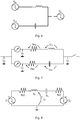
- Fig. 6 illustrates an open end circuit without necessary precautious steps taken. Since the reactive elements are conjugated, or close to conjugated, this is a resonant circuit for the power frequency with a line to line voltage across. The voltages across the elements increase rapidly to extreme levels and therefore the resonant circuit must be broken as early as possible.
- a fast protection device such as a CapThor® device, may be used for swift bypass of the capacitor.
- IPC240 interconnecting device are close to constant power flow for all anticipated network topologies and operating points with power throughput chosen through fixed values of L and C, and fault current contribution is less than the nominal pre-specified current through the device.
- An open circuit misoperation on the sending side (S) of the IPC device is here denoted OCS.
- An open circuit misoperation on the receiving side (R) of the IPC device is here denoted OCR.
- a one phase equivalent view of the circuit is used to define the voltage names, which is illustrated in Fig. 7 .
- U_s represent sending end phase voltage to ground.
- U_r represent receiving end phase voltage to ground.
- U_1 represent phase shifted voltage inductive branch to ground.
- U_2 represent phase shifted voltage capacitive branch to ground.
- U_R/2 represent voltage drop across resistance.
- U_XL represent voltage drop across inductance.
- U_XC represent voltage drop across capacitance.
- phase shifts are known to be the adjacent phase voltages for the IPC240, the circuit during one end open circuit can be redrawn for one phase as illustrated in Fig. 8 .
- the voltages U_s, U_1 and U_2 are chosen.
- the voltage U_s only defines which one of the three symmetric phases is in focus. It will be the A phase throughout this section.
- U_1 and U_2 can thereby be selected as phase B or C.
- OCR receiving end opening case
- ⁇ denotes the angle of each phasor.
- the presented solution has varistors parallel to the IPC device, i.e. between the U_s and U_r nodes, instead of to ground at either end.
- the voltage across them varies and assuming that varistors parallel to the IPC device and varistors to ground have equal ratings, the following can be deduced:
- a reason for use of a city infeed cable IPC application is that load increase at a city bus requires extra transfer capacity.
- Solutions to the above problems may e.g. be:
- a PST may be used to solve the power flow division problem.
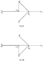
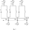
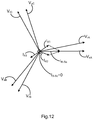
- FIG. 11 shows an IPC240 extracted from its network with all resistances neglected, with conjugated elements connected to two ends of the same network, with bolted three phase fault to ground on receiving side. Assuming a three phase fault to ground occurs on the receiving side, as shown, and assuming that sending side voltages are not reduced during the fault, a resulting phasor diagram is shown in Fig. 12 .
- the current through R-Sa is the sum of the currents in X1 and X2 which are caused by two different voltages, which is illustrated in equation 2. Hence they don't add up to zero.
- the current through circuit breaker S-Sc only consists of the DC-decay from the discharge of the inductance.
- the current magnitude in R-Sa can be calculated as in Equation 3.
- the equation is graphically deduced from Fig. 12 .
- the nominal current in one of the receiving end breakers can, with the same conditions but nominal operation, be calculated as in Equation 4.
- the fault current contribution from the IPC is ideally equal to the nominal current of the device.
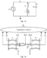
- Equation 5 The current I in Fig. 13 can be approximated by Equation 5 for negligible capacitor resistance.
- U SB is the sending end voltage
- ⁇ 0 is the resonance frequency
- C is the capacitance
- L is the reactor inductance
- r is the reactor resistance.
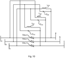
- Connecting varistors parallel to the IPC device is presented herein. Connecting the varistors parallel to the IPC device allows for triggered gaps or other fast varistor bypass solutions. Thereby the required energy handling capacity of the varistors may be limited since the resonance can be disrupted by the bypass. Bypassing a varistor parallel to a reactive element disrupts a series resonance in open circuit conditions but is the equivalence of a bolted phase-to-phase fault in nominal conditions. Bypassing a varistor parallel to the entire device disrupts a series resonance in open circuit conditions but is the equivalence of bypassing the device in nominal conditions. The latter has a less severe impact in case of misoperation.
- Fig. 10 illustrates connection of varistors parallel to the IPC device.
- the rating of the varistors parallel to the device is selected at the same level as varistors connected to ground (marginally higher than the line-to-ground voltage), these varistors will keep the voltage across the reactive elements lower for forward flow receiving end open circuit resonance. Thereby sending end line-to-ground energy handling varistors can be eliminated for a unidirectional device.
- the benefits from the presented configuration include a lower voltage across the reactive elements during resonance as well as lower current.
- a sending end circuit breaker, S-S (as illustrated in Fig. 2 ) is unintentionally opened at ti leaving the circuit in resonance.
- the current through the varistors which are due to the voltage magnitude increase, triggers the opening of the far end breaker, V R , at t2.
- the varistors limit the voltage across the reactive elements until the circuit is deenergized from the opening of V R .
- the nominal voltage across the varistors is only a fraction of the line-to-neutral voltage inherent to connections to ground or to the line-to-line voltage inherent to a connection parallel to reactive elements. This would not only affect the leakage current but also allow for a reduction of the rated voltage of the varistor.
- the rating of the varistors parallel to the device is selected at a lower level than varistors connected to ground, preferably about half the line-to-ground voltage, there are several further benefits:
- a damping reactor may be connected in series with the varistor to limit the dl/dt of such currents. Simulations have shown that a 3 mH reactor is sufficient for a 130 kV system voltage application with a short circuit level of 16 kArms. The size of the initial spike with a 3 mH damping reactor varies with varistor rating.
- the varistors may e.g. be metal-oxide varistors.
- the varistor connection described herein is a novel way of protecting the IPC device.
- the varistor parallel to the IPC device may replace one or both of ground connected (end side) varistors and potentially lower the required energy rating of a single remaining varistor connected parallel to the device. This is done with improved protective performance and, for low enough rating, enabling the topology without branch current breakers otherwise troubled by slowly decaying DC-components in the circuit breakers during faults to ground including multiple phases.
- the theoretical maximum benefit would be to reduce the amount of parallel varistor energy handling capacity by two thirds, reducing the required voltage and current for the remaining varistors, reducing the required voltage and current rating for the reactive elements, and allowing for the removal of up to two sets of circuit breakers.
- Fig. 14 schematically illustrates an internal three phase fault with an IPC device according to an embodiment.
- an interphase power controller (IPC) device comprising a first side phase line connection point a, a first side phase line connection point b and a first side phase line connection point c, a second side phase line connection point a, a second side phase line connection point b and a second side phase line connection point c, a first inductor L AB connecting the first side phase line connection point a to the second side phase line connection point b, and a first capacitor C AC connecting the first side phase line connection point a to the second side phase line connection point c, a second inductor L BC connecting the first side phase line connection point b to the second side phase line connection point c, and a second capacitor C BA connecting the first side phase line connection point b to the second side phase line connection point a, a third inductor L CA connecting the first side phase line connection point c to the second side phase line connection point a, and a third capacitor C CB connecting the first side phase line connection point c to the second side phase line
- the IPC may be a passive IPC device.
- the first to third varistors may have a rated voltage for series resonance energy dissipation of open circuits on one side of the IPC device.
- the first to third varistors may alternatively have a rated voltage for series resonance energy dissipation of open circuits on both sides of the IPC device.
- the rated voltage may be half of a line-to-ground voltage for the IPC device.
- the first to third inductor may each have the same impedance value, and the first to third capacitor may each have a conjugate value thereof.
- a method for interphase power control of an interphase power controller (IPC) device comprises connecting a first side phase line connection point a to a second side phase line connection point b through a first inductor L AB , connecting the first side phase line connection point a to a second side phase line connection point c through a first capacitor C AC , connecting a first side phase line connection point b to the second side phase line connection point c through a second inductor L BC , connecting the first side phase line connection point b to a second side phase line connection point a through a second capacitor C BA , connecting a first side phase line connection point c to the second side phase line connection point a through a third inductor L CA , connecting the first side phase line connection point c to the second side phase line connection point b through a third capacitor C CB , connecting the first side phase line connection point a to the second side phase line connection point a through a first varistor Var A , connecting the first side phase line connection point
- the method may further comprise providing energy dissipation of an open circuit on one side of the IPC by series resonance through the first to third varistors.
- the method may alternatively comprise providing energy dissipation of an open circuit on both sides of the IPC by series resonance through the first to third varistors.
Landscapes
- Engineering & Computer Science (AREA)
- Power Engineering (AREA)
- Emergency Protection Circuit Devices (AREA)
Claims (12)
- Dispositif régulateur de puissance interphase (IPC), comprenant :un premier point de branchement de ligne de phase latérale a, un premier point de branchement de ligne de phase latérale b et un premier point de branchement de ligne de phase latérale c ;un deuxième point de branchement de ligne de phase latérale a, un deuxième point de branchement de ligne de phase latérale b et un deuxième point de branchement de ligne de phase latérale c ;une première bobine d'induction (LAB) branchant le premier point de branchement de ligne de phase latérale a au deuxième point de branchement de ligne de phase latérale b,une deuxième bobine d'induction (LBC) branchant le premier point de branchement de ligne de phase latérale b au deuxième point de branchement de ligne de phase latérale c,une troisième bobine d'induction (LCA) branchant le premier point de branchement de ligne de phase latérale c au deuxième point de branchement de ligne de phase latérale a,caractérisé par un premier condensateur (CAC) branchant le premier point de branchement de ligne de phase latérale a au deuxième point de branchement de ligne de phase latérale c ; un deuxième condensateur (CBA) branchant le premier point de branchement de ligne de phase latérale b au deuxième point de branchement de ligne de phase latérale a ; un troisième condensateur (CCB) branchant le premier point de branchement de ligne de phase latérale c au deuxième point de branchement de ligne de phase latérale b ;une première varistance (VarA) branchant le premier point de branchement de ligne de phase latérale a au deuxième point de branchement de ligne de phase latérale a ;une deuxième varistance (VarB) branchant le premier point de branchement de ligne de phase latérale b au deuxième point de branchement de ligne de phase latérale b ; etune troisième varistance (VarC) branchant le premier point de branchement de ligne de phase latérale c au deuxième point de branchement de ligne de phase latérale c.
- Dispositif IPC selon la revendication 1, le dispositif IPC étant un dispositif IPC passif.
- Dispositif IPC selon la revendication 1 ou 2, dans lequel les première à troisième varistances ont une tension nominale pour la dissipation d'énergie par résonance série de circuits ouverts sur un côté de l'IPC.
- Dispositif IPC selon la revendication 1 ou 2, dans lequel les première à troisième varistances ont une tension nominale pour la dissipation d'énergie par résonance série de circuits ouverts sur les deux côtés de l'IPC.
- Dispositif IPC selon l'une quelconque des revendications 3 à 4, dans lequel la tension nominale est la moitié d'une tension ligne-terre pour le dispositif IPC.
- Dispositif IPC selon l'une quelconque des revendications 1 à 5, dans lequel les première à troisième bobines d'induction ont chacune la même valeur d'impédance, et les premier à troisième condensateurs ont chacun une valeur conjuguée de celle-ci.
- Procédé pour la régulation de puissance interphase par un dispositif régulateur de puissance interphase (IPC), comprenant :le branchement d'un premier point de branchement de ligne de phase latérale a à un deuxième point de branchement de ligne de phase latérale b par le biais d'une première bobine d'induction (LAB) ; etle branchement d'un premier point de branchement de ligne de phase latérale b au deuxième point de branchement de ligne de phase latérale c par le biais d'une deuxième bobine d'induction (LBC),le branchement d'un premier point de branchement de ligne de phase latérale c au deuxième point de branchement de ligne de phase latérale a par le biais d'une troisième bobine d'induction (LCA) ;caractérisé parle branchement du premier point de branchement de ligne de phase latérale a à un deuxième point de branchement de ligne de phase latérale c par le biais d'un premier condensateur (CAC) ;le branchement du premier point de branchement de ligne de phase latérale b à un deuxième point de branchement de ligne de phase latérale a par le biais d'un deuxième condensateur (CBA) ;le branchement du premier point de branchement de ligne de phase latérale c au deuxième point de branchement de ligne de phase latérale b par le biais d'un troisième condensateur (CCB) ;le branchement du premier point de branchement de ligne de phase latérale a au deuxième point de branchement de ligne de phase latérale a par le biais d'une première varistance (VarA) ;le branchement du premier point de branchement de ligne de phase latérale b au deuxième point de branchement de ligne de phase latérale b par le biais d'une deuxième varistance (VarB) ; etle branchement du premier point de branchement de ligne de phase latérale c au deuxième point de branchement de ligne de phase latérale c par le biais d'une troisième varistance (VarC).
- Procédé selon la revendication 7, dans lequel le dispositif IPC est un dispositif IPC passif.
- Procédé selon la revendication 7 ou 8, comprenant :
la réalisation d'une dissipation d'énergie d'un circuit ouvert sur un côté de l'IPC par résonance série à travers les première à troisième varistances. - Procédé selon la revendication 7 ou 8, comprenant :
la réalisation d'une dissipation d'énergie d'un circuit ouvert sur les deux côtés de l'IPC par résonance série à travers les première à troisième varistances. - Procédé selon l'une quelconque des revendications 7 à 10, dans lequel les première à troisième varistances ont une tension nominale égale à la moitié d'une tension ligne-terre pour le dispositif IPC.
- Procédé selon l'une quelconque des revendications 7 à 11, dans lequel les première à troisième bobines d'induction ont chacune la même valeur d'impédance, et les premier à troisième condensateurs ont chacun une valeur conjuguée de celle-ci.
Applications Claiming Priority (1)
| Application Number | Priority Date | Filing Date | Title |
|---|---|---|---|
| PCT/EP2016/079300 WO2018099555A1 (fr) | 2016-11-30 | 2016-11-30 | Régulateur de puissance inter-phase |
Publications (2)
| Publication Number | Publication Date |
|---|---|
| EP3549223A1 EP3549223A1 (fr) | 2019-10-09 |
| EP3549223B1 true EP3549223B1 (fr) | 2020-11-04 |
Family
ID=57485462
Family Applications (1)
| Application Number | Title | Priority Date | Filing Date |
|---|---|---|---|
| EP16806031.7A Active EP3549223B1 (fr) | 2016-11-30 | 2016-11-30 | Contrôleur de puissance interphasé |
Country Status (2)
| Country | Link |
|---|---|
| EP (1) | EP3549223B1 (fr) |
| WO (1) | WO2018099555A1 (fr) |
Family Cites Families (1)
| Publication number | Priority date | Publication date | Assignee | Title |
|---|---|---|---|---|
| EP0681755B1 (fr) * | 1993-01-29 | 1996-09-04 | Citeq | Procede et appareil d'interconnexion de deux reseaux a courant alternatif polyphase synchrone |
-
2016
- 2016-11-30 EP EP16806031.7A patent/EP3549223B1/fr active Active
- 2016-11-30 WO PCT/EP2016/079300 patent/WO2018099555A1/fr not_active Ceased
Non-Patent Citations (1)
| Title |
|---|
| None * |
Also Published As
| Publication number | Publication date |
|---|---|
| WO2018099555A1 (fr) | 2018-06-07 |
| EP3549223A1 (fr) | 2019-10-09 |
Similar Documents
| Publication | Publication Date | Title |
|---|---|---|
| Das | Passive filters-potentialities and limitations | |
| Ghanbari et al. | Unidirectional fault current limiter: An efficient interface between the microgrid and main network | |
| EP2577833B1 (fr) | Agencement d'interfaçage entre des systèmes alternatif et continu, au moyen d'un commutateur de mise à la terre | |
| US7986132B2 (en) | Static var compensator apparatus | |
| Aithal et al. | Performance of an electrical distribution network with Soft Open Point during a grid side AC fault | |
| Noh et al. | Development of protective schemes for hybrid AC/DC low-voltage distribution system | |
| CN102334257B (zh) | 多相无功功率补偿器 | |
| Hagh et al. | Non‐superconducting fault current limiters | |
| CN109581148A (zh) | 一种新能源电场联络线的故障选相方法 | |
| Arikan et al. | A new approach to limit fault current with series–parallel resonance strategy | |
| Dewadasa et al. | Distance protection solution for a converter controlled microgrid | |
| Kim et al. | A study on power-flow and short-circuit algorithms capable of analyzing the effect of load current on fault current using the bus impedance matrix | |
| EP2983262A1 (fr) | Dispositif de limitation de courant | |
| Badrzadeh | Transient recovery voltages caused by capacitor switching in wind power plants | |
| Wadhawan et al. | A Review on Power Quality Problems and Improvement Techniques | |
| Jovcic et al. | Developing regional, radial DC grids and their interconnection into large DC grids | |
| Patcharoen et al. | Simulation analysis of the switching of 230 kV substation shunt capacitor banks with a 6% series reactor for limiting transient inrush currents and oscillation overvoltage | |
| Kucukaydin et al. | A comparative study on applicability of parallel resonance type fault current limiters in power systems | |
| EP3549223B1 (fr) | Contrôleur de puissance interphasé | |
| JP7538457B1 (ja) | 保護システム | |
| Barker et al. | HVDC line commutated converters (LCC) and their application for power transmission | |
| Firouzi et al. | Effect of superconducting fault current limiters on successful interruption of circuit breakers | |
| Jain et al. | Limiting fault current in a power system network by SFCL: A step input approach | |
| Sham et al. | Development of adaptive distance relay for STATCOM connected transmission line | |
| Chen et al. | Parameter design and performance simulation of a 10 kV voltage compensation type active superconducting fault current limiter |
Legal Events
| Date | Code | Title | Description |
|---|---|---|---|
| STAA | Information on the status of an ep patent application or granted ep patent |
Free format text: STATUS: UNKNOWN |
|
| STAA | Information on the status of an ep patent application or granted ep patent |
Free format text: STATUS: THE INTERNATIONAL PUBLICATION HAS BEEN MADE |
|
| PUAI | Public reference made under article 153(3) epc to a published international application that has entered the european phase |
Free format text: ORIGINAL CODE: 0009012 |
|
| STAA | Information on the status of an ep patent application or granted ep patent |
Free format text: STATUS: REQUEST FOR EXAMINATION WAS MADE |
|
| 17P | Request for examination filed |
Effective date: 20190625 |
|
| AK | Designated contracting states |
Kind code of ref document: A1 Designated state(s): AL AT BE BG CH CY CZ DE DK EE ES FI FR GB GR HR HU IE IS IT LI LT LU LV MC MK MT NL NO PL PT RO RS SE SI SK SM TR |
|
| AX | Request for extension of the european patent |
Extension state: BA ME |
|
| DAV | Request for validation of the european patent (deleted) | ||
| DAX | Request for extension of the european patent (deleted) | ||
| RIC1 | Information provided on ipc code assigned before grant |
Ipc: H02J 3/06 20060101AFI20200306BHEP Ipc: H02H 7/28 20060101ALI20200306BHEP |
|
| GRAP | Despatch of communication of intention to grant a patent |
Free format text: ORIGINAL CODE: EPIDOSNIGR1 |
|
| STAA | Information on the status of an ep patent application or granted ep patent |
Free format text: STATUS: GRANT OF PATENT IS INTENDED |
|
| INTG | Intention to grant announced |
Effective date: 20200519 |
|
| RAP1 | Party data changed (applicant data changed or rights of an application transferred) |
Owner name: ABB POWER GRIDS SWITZERLAND AG |
|
| GRAS | Grant fee paid |
Free format text: ORIGINAL CODE: EPIDOSNIGR3 |
|
| GRAA | (expected) grant |
Free format text: ORIGINAL CODE: 0009210 |
|
| STAA | Information on the status of an ep patent application or granted ep patent |
Free format text: STATUS: THE PATENT HAS BEEN GRANTED |
|
| AK | Designated contracting states |
Kind code of ref document: B1 Designated state(s): AL AT BE BG CH CY CZ DE DK EE ES FI FR GB GR HR HU IE IS IT LI LT LU LV MC MK MT NL NO PL PT RO RS SE SI SK SM TR |
|
| REG | Reference to a national code |
Ref country code: GB Ref legal event code: FG4D |
|
| REG | Reference to a national code |
Ref country code: CH Ref legal event code: EP |
|
| REG | Reference to a national code |
Ref country code: AT Ref legal event code: REF Ref document number: 1332068 Country of ref document: AT Kind code of ref document: T Effective date: 20201115 |
|
| REG | Reference to a national code |
Ref country code: IE Ref legal event code: FG4D |
|
| REG | Reference to a national code |
Ref country code: DE Ref legal event code: R096 Ref document number: 602016047323 Country of ref document: DE |
|
| PGFP | Annual fee paid to national office [announced via postgrant information from national office to epo] |
Ref country code: GB Payment date: 20201223 Year of fee payment: 5 Ref country code: DE Payment date: 20201119 Year of fee payment: 5 |
|
| REG | Reference to a national code |
Ref country code: NL Ref legal event code: MP Effective date: 20201104 |
|
| REG | Reference to a national code |
Ref country code: AT Ref legal event code: MK05 Ref document number: 1332068 Country of ref document: AT Kind code of ref document: T Effective date: 20201104 |
|
| PG25 | Lapsed in a contracting state [announced via postgrant information from national office to epo] |
Ref country code: FI Free format text: LAPSE BECAUSE OF FAILURE TO SUBMIT A TRANSLATION OF THE DESCRIPTION OR TO PAY THE FEE WITHIN THE PRESCRIBED TIME-LIMIT Effective date: 20201104 Ref country code: GR Free format text: LAPSE BECAUSE OF FAILURE TO SUBMIT A TRANSLATION OF THE DESCRIPTION OR TO PAY THE FEE WITHIN THE PRESCRIBED TIME-LIMIT Effective date: 20210205 Ref country code: PT Free format text: LAPSE BECAUSE OF FAILURE TO SUBMIT A TRANSLATION OF THE DESCRIPTION OR TO PAY THE FEE WITHIN THE PRESCRIBED TIME-LIMIT Effective date: 20210304 Ref country code: RS Free format text: LAPSE BECAUSE OF FAILURE TO SUBMIT A TRANSLATION OF THE DESCRIPTION OR TO PAY THE FEE WITHIN THE PRESCRIBED TIME-LIMIT Effective date: 20201104 Ref country code: NO Free format text: LAPSE BECAUSE OF FAILURE TO SUBMIT A TRANSLATION OF THE DESCRIPTION OR TO PAY THE FEE WITHIN THE PRESCRIBED TIME-LIMIT Effective date: 20210204 |
|
| PG25 | Lapsed in a contracting state [announced via postgrant information from national office to epo] |
Ref country code: BG Free format text: LAPSE BECAUSE OF FAILURE TO SUBMIT A TRANSLATION OF THE DESCRIPTION OR TO PAY THE FEE WITHIN THE PRESCRIBED TIME-LIMIT Effective date: 20210204 Ref country code: IS Free format text: LAPSE BECAUSE OF FAILURE TO SUBMIT A TRANSLATION OF THE DESCRIPTION OR TO PAY THE FEE WITHIN THE PRESCRIBED TIME-LIMIT Effective date: 20210304 Ref country code: PL Free format text: LAPSE BECAUSE OF FAILURE TO SUBMIT A TRANSLATION OF THE DESCRIPTION OR TO PAY THE FEE WITHIN THE PRESCRIBED TIME-LIMIT Effective date: 20201104 Ref country code: LV Free format text: LAPSE BECAUSE OF FAILURE TO SUBMIT A TRANSLATION OF THE DESCRIPTION OR TO PAY THE FEE WITHIN THE PRESCRIBED TIME-LIMIT Effective date: 20201104 Ref country code: AT Free format text: LAPSE BECAUSE OF FAILURE TO SUBMIT A TRANSLATION OF THE DESCRIPTION OR TO PAY THE FEE WITHIN THE PRESCRIBED TIME-LIMIT Effective date: 20201104 Ref country code: ES Free format text: LAPSE BECAUSE OF FAILURE TO SUBMIT A TRANSLATION OF THE DESCRIPTION OR TO PAY THE FEE WITHIN THE PRESCRIBED TIME-LIMIT Effective date: 20201104 Ref country code: SE Free format text: LAPSE BECAUSE OF FAILURE TO SUBMIT A TRANSLATION OF THE DESCRIPTION OR TO PAY THE FEE WITHIN THE PRESCRIBED TIME-LIMIT Effective date: 20201104 |
|
| REG | Reference to a national code |
Ref country code: LT Ref legal event code: MG9D |
|
| PG25 | Lapsed in a contracting state [announced via postgrant information from national office to epo] |
Ref country code: HR Free format text: LAPSE BECAUSE OF FAILURE TO SUBMIT A TRANSLATION OF THE DESCRIPTION OR TO PAY THE FEE WITHIN THE PRESCRIBED TIME-LIMIT Effective date: 20201104 |
|
| REG | Reference to a national code |
Ref country code: CH Ref legal event code: PL |
|
| PG25 | Lapsed in a contracting state [announced via postgrant information from national office to epo] |
Ref country code: RO Free format text: LAPSE BECAUSE OF FAILURE TO SUBMIT A TRANSLATION OF THE DESCRIPTION OR TO PAY THE FEE WITHIN THE PRESCRIBED TIME-LIMIT Effective date: 20201104 Ref country code: SK Free format text: LAPSE BECAUSE OF FAILURE TO SUBMIT A TRANSLATION OF THE DESCRIPTION OR TO PAY THE FEE WITHIN THE PRESCRIBED TIME-LIMIT Effective date: 20201104 Ref country code: EE Free format text: LAPSE BECAUSE OF FAILURE TO SUBMIT A TRANSLATION OF THE DESCRIPTION OR TO PAY THE FEE WITHIN THE PRESCRIBED TIME-LIMIT Effective date: 20201104 Ref country code: CZ Free format text: LAPSE BECAUSE OF FAILURE TO SUBMIT A TRANSLATION OF THE DESCRIPTION OR TO PAY THE FEE WITHIN THE PRESCRIBED TIME-LIMIT Effective date: 20201104 Ref country code: SM Free format text: LAPSE BECAUSE OF FAILURE TO SUBMIT A TRANSLATION OF THE DESCRIPTION OR TO PAY THE FEE WITHIN THE PRESCRIBED TIME-LIMIT Effective date: 20201104 Ref country code: LT Free format text: LAPSE BECAUSE OF FAILURE TO SUBMIT A TRANSLATION OF THE DESCRIPTION OR TO PAY THE FEE WITHIN THE PRESCRIBED TIME-LIMIT Effective date: 20201104 Ref country code: LU Free format text: LAPSE BECAUSE OF NON-PAYMENT OF DUE FEES Effective date: 20201130 |
|
| REG | Reference to a national code |
Ref country code: DE Ref legal event code: R097 Ref document number: 602016047323 Country of ref document: DE |
|
| REG | Reference to a national code |
Ref country code: BE Ref legal event code: MM Effective date: 20201130 |
|
| PG25 | Lapsed in a contracting state [announced via postgrant information from national office to epo] |
Ref country code: MC Free format text: LAPSE BECAUSE OF FAILURE TO SUBMIT A TRANSLATION OF THE DESCRIPTION OR TO PAY THE FEE WITHIN THE PRESCRIBED TIME-LIMIT Effective date: 20201104 Ref country code: DK Free format text: LAPSE BECAUSE OF FAILURE TO SUBMIT A TRANSLATION OF THE DESCRIPTION OR TO PAY THE FEE WITHIN THE PRESCRIBED TIME-LIMIT Effective date: 20201104 Ref country code: CH Free format text: LAPSE BECAUSE OF NON-PAYMENT OF DUE FEES Effective date: 20201130 Ref country code: LI Free format text: LAPSE BECAUSE OF NON-PAYMENT OF DUE FEES Effective date: 20201130 |
|
| REG | Reference to a national code |
Ref country code: IE Ref legal event code: MM4A |
|
| PLBE | No opposition filed within time limit |
Free format text: ORIGINAL CODE: 0009261 |
|
| STAA | Information on the status of an ep patent application or granted ep patent |
Free format text: STATUS: NO OPPOSITION FILED WITHIN TIME LIMIT |
|
| 26N | No opposition filed |
Effective date: 20210805 |
|
| PG25 | Lapsed in a contracting state [announced via postgrant information from national office to epo] |
Ref country code: NL Free format text: LAPSE BECAUSE OF FAILURE TO SUBMIT A TRANSLATION OF THE DESCRIPTION OR TO PAY THE FEE WITHIN THE PRESCRIBED TIME-LIMIT Effective date: 20201104 Ref country code: FR Free format text: LAPSE BECAUSE OF NON-PAYMENT OF DUE FEES Effective date: 20210104 Ref country code: IT Free format text: LAPSE BECAUSE OF FAILURE TO SUBMIT A TRANSLATION OF THE DESCRIPTION OR TO PAY THE FEE WITHIN THE PRESCRIBED TIME-LIMIT Effective date: 20201104 Ref country code: IE Free format text: LAPSE BECAUSE OF NON-PAYMENT OF DUE FEES Effective date: 20201130 Ref country code: AL Free format text: LAPSE BECAUSE OF FAILURE TO SUBMIT A TRANSLATION OF THE DESCRIPTION OR TO PAY THE FEE WITHIN THE PRESCRIBED TIME-LIMIT Effective date: 20201104 |
|
| PG25 | Lapsed in a contracting state [announced via postgrant information from national office to epo] |
Ref country code: SI Free format text: LAPSE BECAUSE OF FAILURE TO SUBMIT A TRANSLATION OF THE DESCRIPTION OR TO PAY THE FEE WITHIN THE PRESCRIBED TIME-LIMIT Effective date: 20201104 |
|
| PG25 | Lapsed in a contracting state [announced via postgrant information from national office to epo] |
Ref country code: IS Free format text: LAPSE BECAUSE OF FAILURE TO SUBMIT A TRANSLATION OF THE DESCRIPTION OR TO PAY THE FEE WITHIN THE PRESCRIBED TIME-LIMIT Effective date: 20210304 Ref country code: TR Free format text: LAPSE BECAUSE OF FAILURE TO SUBMIT A TRANSLATION OF THE DESCRIPTION OR TO PAY THE FEE WITHIN THE PRESCRIBED TIME-LIMIT Effective date: 20201104 Ref country code: MT Free format text: LAPSE BECAUSE OF FAILURE TO SUBMIT A TRANSLATION OF THE DESCRIPTION OR TO PAY THE FEE WITHIN THE PRESCRIBED TIME-LIMIT Effective date: 20201104 Ref country code: CY Free format text: LAPSE BECAUSE OF FAILURE TO SUBMIT A TRANSLATION OF THE DESCRIPTION OR TO PAY THE FEE WITHIN THE PRESCRIBED TIME-LIMIT Effective date: 20201104 |
|
| REG | Reference to a national code |
Ref country code: DE Ref legal event code: R119 Ref document number: 602016047323 Country of ref document: DE |
|
| PG25 | Lapsed in a contracting state [announced via postgrant information from national office to epo] |
Ref country code: MK Free format text: LAPSE BECAUSE OF FAILURE TO SUBMIT A TRANSLATION OF THE DESCRIPTION OR TO PAY THE FEE WITHIN THE PRESCRIBED TIME-LIMIT Effective date: 20201104 |
|
| GBPC | Gb: european patent ceased through non-payment of renewal fee |
Effective date: 20211130 |
|
| PG25 | Lapsed in a contracting state [announced via postgrant information from national office to epo] |
Ref country code: BE Free format text: LAPSE BECAUSE OF NON-PAYMENT OF DUE FEES Effective date: 20201130 |
|
| PG25 | Lapsed in a contracting state [announced via postgrant information from national office to epo] |
Ref country code: GB Free format text: LAPSE BECAUSE OF NON-PAYMENT OF DUE FEES Effective date: 20211130 Ref country code: DE Free format text: LAPSE BECAUSE OF NON-PAYMENT OF DUE FEES Effective date: 20220601 |