EP3549367B1 - Appareil et procédé de commande de flux de données dans un système de communication sans fil - Google Patents
Appareil et procédé de commande de flux de données dans un système de communication sans fil Download PDFInfo
- Publication number
- EP3549367B1 EP3549367B1 EP17881508.0A EP17881508A EP3549367B1 EP 3549367 B1 EP3549367 B1 EP 3549367B1 EP 17881508 A EP17881508 A EP 17881508A EP 3549367 B1 EP3549367 B1 EP 3549367B1
- Authority
- EP
- European Patent Office
- Prior art keywords
- qos
- qos flow
- drb
- pdu session
- mapping
- Prior art date
- Legal status (The legal status is an assumption and is not a legal conclusion. Google has not performed a legal analysis and makes no representation as to the accuracy of the status listed.)
- Active
Links
Images






Classifications
-
- H—ELECTRICITY
- H04—ELECTRIC COMMUNICATION TECHNIQUE
- H04W—WIRELESS COMMUNICATION NETWORKS
- H04W28/00—Network traffic management; Network resource management
- H04W28/02—Traffic management, e.g. flow control or congestion control
-
- H—ELECTRICITY
- H04—ELECTRIC COMMUNICATION TECHNIQUE
- H04W—WIRELESS COMMUNICATION NETWORKS
- H04W28/00—Network traffic management; Network resource management
- H04W28/02—Traffic management, e.g. flow control or congestion control
- H04W28/0231—Traffic management, e.g. flow control or congestion control based on communication conditions
- H04W28/0242—Determining whether packet losses are due to overload or to deterioration of radio communication conditions
-
- H—ELECTRICITY
- H04—ELECTRIC COMMUNICATION TECHNIQUE
- H04W—WIRELESS COMMUNICATION NETWORKS
- H04W28/00—Network traffic management; Network resource management
- H04W28/02—Traffic management, e.g. flow control or congestion control
- H04W28/0252—Traffic management, e.g. flow control or congestion control per individual bearer or channel
-
- H—ELECTRICITY
- H04—ELECTRIC COMMUNICATION TECHNIQUE
- H04W—WIRELESS COMMUNICATION NETWORKS
- H04W28/00—Network traffic management; Network resource management
- H04W28/02—Traffic management, e.g. flow control or congestion control
- H04W28/0252—Traffic management, e.g. flow control or congestion control per individual bearer or channel
- H04W28/0263—Traffic management, e.g. flow control or congestion control per individual bearer or channel involving mapping traffic to individual bearers or channels, e.g. traffic flow template [TFT]
-
- H—ELECTRICITY
- H04—ELECTRIC COMMUNICATION TECHNIQUE
- H04W—WIRELESS COMMUNICATION NETWORKS
- H04W28/00—Network traffic management; Network resource management
- H04W28/02—Traffic management, e.g. flow control or congestion control
- H04W28/0268—Traffic management, e.g. flow control or congestion control using specific QoS parameters for wireless networks, e.g. QoS class identifier [QCI] or guaranteed bit rate [GBR]
-
- H—ELECTRICITY
- H04—ELECTRIC COMMUNICATION TECHNIQUE
- H04W—WIRELESS COMMUNICATION NETWORKS
- H04W28/00—Network traffic management; Network resource management
- H04W28/02—Traffic management, e.g. flow control or congestion control
- H04W28/08—Load balancing or load distribution
- H04W28/082—Load balancing or load distribution among bearers or channels
-
- H—ELECTRICITY
- H04—ELECTRIC COMMUNICATION TECHNIQUE
- H04W—WIRELESS COMMUNICATION NETWORKS
- H04W36/00—Hand-off or reselection arrangements
- H04W36/0005—Control or signalling for completing the hand-off
- H04W36/0055—Transmission or use of information for re-establishing the radio link
- H04W36/0069—Transmission or use of information for re-establishing the radio link in case of dual connectivity, e.g. decoupled uplink/downlink
- H04W36/00695—Transmission or use of information for re-establishing the radio link in case of dual connectivity, e.g. decoupled uplink/downlink using split of the control plane or user plane
-
- H—ELECTRICITY
- H04—ELECTRIC COMMUNICATION TECHNIQUE
- H04W—WIRELESS COMMUNICATION NETWORKS
- H04W36/00—Hand-off or reselection arrangements
- H04W36/08—Reselecting an access point
-
- H—ELECTRICITY
- H04—ELECTRIC COMMUNICATION TECHNIQUE
- H04W—WIRELESS COMMUNICATION NETWORKS
- H04W76/00—Connection management
- H04W76/10—Connection setup
- H04W76/15—Setup of multiple wireless link connections
-
- H—ELECTRICITY
- H04—ELECTRIC COMMUNICATION TECHNIQUE
- H04W—WIRELESS COMMUNICATION NETWORKS
- H04W76/00—Connection management
- H04W76/20—Manipulation of established connections
- H04W76/22—Manipulation of transport tunnels
-
- H—ELECTRICITY
- H04—ELECTRIC COMMUNICATION TECHNIQUE
- H04W—WIRELESS COMMUNICATION NETWORKS
- H04W80/00—Wireless network protocols or protocol adaptations to wireless operation
- H04W80/06—Transport layer protocols, e.g. TCP [Transport Control Protocol] over wireless
-
- H—ELECTRICITY
- H04—ELECTRIC COMMUNICATION TECHNIQUE
- H04W—WIRELESS COMMUNICATION NETWORKS
- H04W84/00—Network topologies
- H04W84/02—Hierarchically pre-organised networks, e.g. paging networks, cellular networks, WLAN [Wireless Local Area Network] or WLL [Wireless Local Loop]
- H04W84/04—Large scale networks; Deep hierarchical networks
- H04W84/042—Public Land Mobile systems, e.g. cellular systems
-
- H—ELECTRICITY
- H04—ELECTRIC COMMUNICATION TECHNIQUE
- H04W—WIRELESS COMMUNICATION NETWORKS
- H04W88/00—Devices specially adapted for wireless communication networks, e.g. terminals, base stations or access point devices
- H04W88/02—Terminal devices
- H04W88/06—Terminal devices adapted for operation in multiple networks or having at least two operational modes, e.g. multi-mode terminals
Definitions
- the present disclosure relates to a wireless communication system, and more particularly, relates to a master node for dual connectivity in a wireless communication system and a method performed by a master node for dual connectivity in wireless communication system.
- the 5G or pre-5G communication system is also called a ⁇ Beyond 4G Network' or a 'Post LTE System'.
- the 5G communication system is considered to be implemented in higher frequency (mmWave) bands, e.g., 60GHz bands, so as to accomplish higher data rates.
- mmWave e.g., 60GHz bands
- MIMO massive multiple-input multiple-output
- FD-MIMO Full Dimensional MIMO
- array antenna an analog beam forming, large scale antenna techniques are discussed in 5G communication systems.
- RANs Cloud Radio Access Networks
- D2D device-to-device
- wireless backhaul moving network
- cooperative communication Coordinated Multi-Points (CoMP), reception-end interference cancellation and the like.
- CoMP Coordinated Multi-Points
- FQAM Hybrid FSK and QAM Modulation
- SWSC sliding window superposition coding
- ACM advanced coding modulation
- FBMC filter bank multi carrier
- NOMA non-orthogonal multiple access
- SCMA sparse code multiple access
- EP 2884673 A1 discusses bearer arrangement in a beamforming based radio communication system.
- US 2015/215965 A1 discusses a method for receiving a radio resource control message by a user equipment.
- 3rd Generation Partnership Project; Technical Specification group Services and System Aspects, Study on Architecture for Next Generation System (release 14)” 3GPP draft, 23799-DIFF_121_200, XP051199312 discusses a system architecture for next generation mobile networks.
- An aspect of the certain embodiments of the present disclosure is to manage and/or control data flows in wireless communication network.
- data flows in wireless communication network can be efficiently controlled and/or managed.
- the present disclosure describes technology for controlling data flows in a wireless communication system.
- Figure 1 illustrates a wireless communication system according to various embodiments of the present disclosure.
- a base station (BS) 110 a terminal 120, and a terminal 130 are illustrated as the part of nodes using a wireless channel in a wireless communication system.
- Figure 1 illustrates only one BS, but another BS, which is the same as or similar to the BS 110, may be further included.
- the BS 110 is network infrastructure that provides wireless access to the terminals 120 and 130.
- the BS 110 has coverage defined as a predetermined geographical region based on the distance at which a signal can be transmitted.
- the BS 110 may be referred to as "access point (AP),” “eNodeB (eNB),” “5th generation (5G) node,” “wireless point,” “transmission/reception Point (TRP)” as well as “base station.”
- Each of the terminals 120 and 130 is a device used by a user, and performs communication with the BS 110 through a wireless channel. Depending on the case, at least one of the terminals 120 and 130 may operate without user involvement. That is, at least one of the terminals 120 and 130 is a device that performs machine-type communication (MTC) and may not be carried by the user.
- MTC machine-type communication
- Each of the terminals 120 and 130 may be referred to as "user equipment (UE),” “mobile station,” “subscriber station,” “remote terminal,” “wireless terminal,” or “user device” as well as “terminal.”
- the BS 110, the terminal 120, and the terminal 130 may transmit and receive wireless signals in millimeter wave (mmWave) bands (for example, 28 GHz, 30 GHz, 38 GHz, and 60 GHz).
- mmWave millimeter wave
- the BS 110, the terminal 120, and the terminal 130 may perform beamforming.
- the beamforming may include transmission beamforming and reception beamforming. That is, the BS 110, the terminal 120, and the terminal 130 may assign directivity to a transmission signal and a reception signal.
- the BS 110 and the terminals 120 and 130 may select serving beams 112, 113, 121, and 131 through a beam search procedure or a beam management procedure. After that, communications may be performed using resources having a quasi co-located relationship with resources carrying the serving beams 112, 113, 121, and 131.
- a first antenna port and a second antenna ports are considered to be quasi co-located if the large-scale properties of the channel over which a symbol on the first antenna port is conveyed can be inferred from the channel over which a symbol on the second antenna port is conveyed.
- the large-scale properties may include one or more of delay spread, doppler spread, doppler shift, average gain, average delay, and spatial Rx parameters.
- Figure 2 illustrates a network device 200 in the wireless communication system according to various embodiments of the present disclosure.
- a structure exemplified at Figure 2 may be understood as a structure of the network device 200, which may comprises at least one of the BS 110, serving gateway (S-GW), mobility management entity (MME), or other network entities included in a core network.
- the BS 110 may be a master eNB (MeNB), or a secondary eNB (SeNB).
- MeNB master eNB
- SeNB secondary eNB
- the term "-module”, “-unit” or “-er” used hereinafter may refer to the unit for processing at least one function or operation and may be implemented in hardware, software, or a combination of hardware and software.
- the network device may include a wireless communication interface 210, a backhaul communication interface 220, a storage unit 230, and a controller 240.
- the wireless communication interface 210 performs functions for transmitting and receiving signals through a wireless channel.
- the wireless communication interface 210 may perform a function of conversion between a baseband signal and bitstreams according to a physical layer standard of the system.
- the wireless communication interface 210 in data transmission, the wireless communication interface 210 generates complex symbols by encoding and modulating transmission bitstreams. Further, in data reception, the wireless communication interface 210 reconstructs reception bitstreams by demodulating and decoding the baseband signal.
- the wireless communication interface 210 up-converts the baseband signal into an Radio Frequency (RF) band signal, transmits the converted signal through an antenna, and then down-converts the RF band signal received through the antenna into the baseband signal.
- the wireless communication interface 210 may include a transmission filter, a reception filter, an amplifier, a mixer, an oscillator, a digital-to-analog convertor (DAC), an analog-to-digital convertor (ADC), and the like.
- the wireless communication interface 210 may include a plurality of transmission/reception paths.
- the wireless communication interface 210 may include at least one antenna array consisting of a plurality of antenna elements.
- the wireless communication interface 210 may include a digital unit and an analog unit, and the analog unit may include a plurality of sub-units according to operation power, operation frequency, and the like.
- the digital unit may be implemented as at least one processor (e.g., a digital signal processor (DSP)).
- DSP digital signal processor
- the wireless communication interface 210 transmits and receives the signal as described above. Accordingly, the wireless communication interface 210 may be referred to as a "transmitter” a “receiver,” or a “transceiver.” Further, in the following description, transmission and reception performed through the wireless channel may be used to have a meaning including the processing performed by the wireless communication interface 210 as described above.
- the wireless communication interface 210 may be omitted for some network entities.
- the S-GW, MME, or other network entities in a core network may not comprise the wireless communication interface.
- the backhaul communication interface 220 provides an interface for performing communication with other nodes within the network. That is, the backhaul communication interface 220 converts bitstreams transmitted to another node, for example, another access node, another BS, a higher node, or a core network, from the BS into a physical signal and converts the physical signal received from the other node into the bitstreams.
- another node for example, another access node, another BS, a higher node, or a core network
- the storage unit 230 stores a basic program, an application, and data such as setting information for the operation of the network device 200.
- the storage unit 230 may include a volatile memory, a non-volatile memory, or a combination of volatile memory and non-volatile memory. Further, the storage unit 230 provides stored data in response to a request from the controller 240.
- the controller 240 controls the general operation of the network device 200. For example, the controller 240 transmits and receives a signal through the wireless communication interface 210 or the backhaul communication interface 220. Further, the controller 240 records data in the storage unit 230 and reads the recorded data.
- the controller 240 may performs functions of a protocol stack that is required from a communication standard. According to another implementation, the protocol stack may be included in the wireless communication interface 210. To this end, the controller 240 may include at least one processor.
- the controller 240 may control and/or manage data flows in a wireless communication network.
- the controller 240 may control the network device 200 to perform operations according to the exemplary embodiments of the present disclosure.
- Figure 3 illustrates the terminal in the wireless communication system according to various embodiments of the present disclosure.
- a structure exemplified at Figure 3 may be understood as a structure of the terminal 120 or the terminal 130.
- the term "-module”, “-unit” or “-er” used hereinafter may refer to the unit for processing at least one function or operation, and may be implemented in hardware, software, or a combination of hardware and software.
- the terminal 120 includes a communication interface 310, a storage unit 320, and a controller 330.
- the communication interface 310 performs functions for transmitting/receiving a signal through a wireless channel. For example, the communication interface 310 performs a function of conversion between a baseband signal and bitstreams according to the physical layer standard of the system. For example, in data transmission, the communication interface 310 generates complex symbols by encoding and modulating transmission bitstreams. Also, in data reception, the communication interface 310 reconstructs reception bitstreams by demodulating and decoding the baseband signal. In addition, the communication interface 310 up-converts the baseband signal into an RF band signal, transmits the converted signal through an antenna, and then down-converts the RF band signal received through the antenna into the baseband signal. For example, the communication interface 310 may include a transmission filter, a reception filter, an amplifier, a mixer, an oscillator, a DAC, and an ADC.
- the communication interface 310 may include a plurality of transmission/ reception paths.
- the communication interface 310 may include at least one antenna array consisting of a plurality of antenna elements.
- the wireless communication interface 210 may include a digital circuit and an analog circuit (for example, a radio frequency integrated circuit (RFIC)).
- the digital circuit and the analog circuit may be implemented as one package.
- the digital circuit may be implemented as at least one processor (e.g., a DSP).
- the communication interface 310 may include a plurality of RF chains.
- the communication interface 310 may perform beamforming.
- the communication interface 310 transmits and receives the signal as described above. Accordingly, the communication interface 310 may be referred to as a "transmitter,” a “receiver,” or a “transceiver.” Further, in the following description, transmission and reception performed through the wireless channel is used to have a meaning including the processing performed by the communication interface 310 as described above.
- the storage unit 320 stores a basic program, an application, and data such as setting information for the operation of the terminal 120.
- the storage unit 320 may include a volatile memory, a non-volatile memory, or a combination of volatile memory and non-volatile memory. Further, the storage unit 320 provides stored data in response to a request from the controller 330.
- the controller 330 controls the general operation of the terminal 120. For example, the controller 330 transmits and receives a signal through the communication interface 310. Further, the controller 330 records data in the storage unit 320 and reads the recorded data.
- the controller 330 may performs functions of a protocol stack that is required from a communication standard. According to another implementation, the protocol stack may be included in the communication interface 310. To this end, the controller 330 may include at least one processor or microprocessor, or may play the part of the processor. Further, the part of the communication interface 310 or the controller 330 may be referred to as a communication processor (CP).
- CP communication processor
- the controller 330 may perform operations associated with controlling and/or managing of data flows by the network device 200.
- the controller 330 may control the terminal to perform operations according to the exemplary embodiments of the present disclosure.
- Figure 4 illustrates the communication interface in the wireless communication system according to various embodiments of the present disclosure.
- Figure 4 shows an example for the detailed configuration of the communication interface 210 of Figure 2 or the communication interface 310 of Figure 3 . More specifically, Figure 4 shows elements for performing beamforming as part of the communication interface 210 of Figure 2 or the communication interface 310 of Figure 3 .
- the communication interface 210 or 310 includes an encoding and circuitry 402, a digital circuitry 404, a plurality of transmission paths 406-1 to 406-N, and an analog circuitry 408.
- the encoding and circuitry 402 performs channel encoding.
- a low-density parity check (LDPC) code For the channel encoding, at least one of a low-density parity check (LDPC) code, a convolution code, and a polar code may be used.
- the encoding and circuitry 402 generates modulation symbols by performing constellation mapping.
- LDPC low-density parity check
- the digital circuitry 404 performs beamforming for a digital signal (for example, modulation symbols). To this end, the digital circuitry 404 multiples the modulation symbols by beamforming weighted values.
- the beamforming weighted values may be used for changing the size and phrase of the signal, and may be referred to as a "precoding matrix" or a "precoder.”
- the digital circuitry 404 outputs the digitally beamformed modulation symbols to the plurality of transmission paths 406-1 to 406-N.
- the modulation symbols may be multiplexed, or the same modulation symbols may be provided to the plurality of transmission paths 406-1 to 406-N.
- MIMO multiple input multiple output
- the plurality of transmission paths 406-1 to 406-N convert the digitally beamformed digital signals into analog signals.
- each of the plurality of transmission paths 406-1 to 406-N may include an inverse fast Fourier transform (IFFT) calculation unit, a cyclic prefix (CP) insertion unit, a DAC, and an up-conversion unit.
- the CP insertion unit is for an orthogonal frequency division multiplexing (OFDM) scheme, and may be omitted when another physical layer scheme (for example, a filter bank multi-carrier: FBMC) is applied. That is, the plurality of transmission paths 406-1 to 406-N provide independent signal processing processes for a plurality of streams generated through the digital beamforming. However, depending on the implementation, some of the elements of the plurality of transmission paths 406-1 to 406-N may be used in common.
- OFDM orthogonal frequency division multiplexing
- the analog circuitry 408 performs beamforming for analog signals. To this end, the digital circuitry 404 multiples the analog signals by beamforming weighted values. The beamformed weighted values are used for changing the size and phrase of the signal. More specifically, according to a connection structure between the plurality of transmission paths 406-1 to 406-N and antennas, the analog circuitry 408 may be configured in various ways. For example, each of the plurality of transmission paths 406-1 to 406-N may be connected to one antenna array. In another example, the plurality of transmission paths 406-1 to 406-N may be connected to one antenna array. In still another example, the plurality of transmission paths 406-1 to 406-N may be adaptively connected to one antenna array, or may be connected to two or more antenna arrays.
- EPS bearers In a long term evolution (LTE) system, bearers known as Evolved Packet switched System (EPS) bearers are provided which provide a 1:1 mapping between the User Equipment (UE) or mobile device and the Evolved Packet Core (EPC) at the heart of the network by means of a Data Radio Bearer (DRB).
- UE User Equipment
- EPC Evolved Packet Core
- DRB Data Radio Bearer
- NR new radio
- QoS Quality of Service
- PDU Protocol Data Unit
- RAN Radio Access Network
- Figure 5(b) shows the notion of QoS flows between the UE and the 5G Core Network, via a NR RAN.
- Figure 6 shows a slightly more detailed representation of a 4G implementation, similar to that shown in Figure 5(a) .
- the relationship between the UE, the LTE RAN and the EPC There is a dedicated DRB per EPS bearer between the UE and the LTE RAB and then a dedicated GTP tunnel per EPS bearer between the LTE RAN and the EPC.
- FIG 7 shows the configuration according to an embodiment of the invention in the case of a Dual-Connectivity (DC) implementation.
- DC the radio connection between UE and RAN involves multiple cells (i.e. there is a form of carrier aggregation) and some of these cells are controlled by a Master Node (MN or MeNB in case of LTE) while others are controlled by a Secondary Node (SN or SeNB in case of LTE).
- MN Master Node
- SN Secondary Node
- the cells controlled by MN are referred to as the Master Cell Group (MCG) while the cells controlled by an SN are referred to as an Secondary Cell Group (SCG).
- MCG Master Cell Group
- SCG Secondary Cell Group
- the UE is in communication with an LTE MeNB and an LTE SeNB, in each case via a DRB per EPS bearer.
- data traffic moves between the MeNB and the SeNB.
- MME Mobility Management Entity
- TEID IP address/DL GTP Tunnel Endpoint Identifier
- the EPC is not aware that this IP address/DL GTP TEID corresponds to a different eNB. Further, one eNB can use different IP addresses.
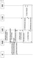
- Figure 8 illustrates the signal flow between UE, MeNB, SeNB, S-GW and MME. This is known from prior art LTE DC operation, but is included for context.
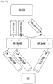
- FIG. 9 shows a non-DC case in 5G.
- a GTP tunnel per PDU session 510, 520 between the NR RAN 600 and the 5GCN 500.
- Each PDU session 510, 520 handles multiple QoS flows, shown by the dotted/dashed lines.
- DRBs 610, 611, 612 handling a number of QoS flows of one PDU session.
- Embodiments of the invention concern the handling of QoS flows upon change of MN (handover), as well as upon addition or change of SN i.e. involving a change of the involved network nodes, which can also be regarded as mobility cases.
- Some of these aspects however equally apply in non-mobility cases e.g. in case of changes regarding the offloading in case of DC.
- DRBs which is a function controlled by the RAN nodes (MN and SN).
- MN and SN RAN nodes
- level 1 and level 2 mobility in the following - are distinguished.
- these mobility levels concern the QoS flow to DRB mapping, i.e. a QoS flow mobility level may occur not involving any actual UE mobility or change of the network node(s) controlling the UEs radio connection.
- the RAN 600 maps different QoS flows of a certain PDU session to one or more DRBs.
- the RAN maps similar flows together on a DRB. Similar flows in this context can mean data flows having similar QoS requirements e.g. similar latency requirements, for instance. Other means of grouping can be implemented as required.
- 5GCN 500 establishes one or more PDU sessions and for each UE, the RAN 600 establishes one or more DRBs per PDU session.
- the RAN 600 maps packets belonging to different PDU sessions to different DRBs. Hence the RAN 600 establishes at least one default DRB for each PDU session.
- Non-Access Stratum (NAS) level packet filters in the UE and the 5GCN associate UL and DL packets with QoS flows.
- AS-level mapping rules in the UE and the RAN associate UL and DL QoS flows with DRBs.
- NAS Non-Access Stratum
- the QoS flow is the finest granularity of QoS differentiation in a PDU session.
- a QoS flow is identified within a PDU session by a QoS Flow ID (QFI) carried in an encapsulation header over NG-U.
- QFI QoS Flow ID
- RAN and 5GC ensure quality of service (e.g. reliability and target delay) by mapping packets to appropriate QoS Flows and DRBs.
- quality of service e.g. reliability and target delay
- a QoS flow is characterised by a QoS profile provided by 5GC to RAN and QoS rule(s) provided by 5GC to the UE.
- the QoS profile is used by RAN to determine the treatment on the radio interface while the QoS rules dictates the mapping between uplink User Plane traffic and QoS flows to the UE.
- a QoS flow may either be Guaranteed Bitrate (GBR) or "Non-GBR" depending on its profile.
- GBR Guaranteed Bitrate
- Non-GBR Non-GBR
- the data radio bearer defines the packet treatment on the radio interface (Uu).
- a DRB serves packets with the same packet forwarding treatment. Separate DRBs may be established for QoS flows requiring different packet forwarding treatment.
- the RAN maps QoS Flows to DRBs based on NG-U marking (QFI) and the associated QoS profiles.
- the UE marks uplink packets over Uu with the QFI for the purposes of marking forwarded packets to the CN.
- the RAN may control the mapping of QoS Flows to DRB in two different ways:
- the UE shall always apply the latest update of the mapping rules regardless of whether it is performed via reflective mapping or explicit configuration.
- a default DRB For each PDU session, a default DRB is configured. If an incoming UL packet matches neither an RRC configured nor a reflective "QoS Flow ID to DRB mapping", the UE shall map that packet to the default DRB of the PDU session.
- each PDU session it is up to NG-RAN how to map multiple QoS flows to a DRB.
- the RAN may map a GBR flow and a non-GBR flow, or more than one GBR flow to the same DRB.
- the timing of establishing non-default DRB(s) between RAN and UE for QoS flow configured during establishing a PDU session can be different from the time when the PDU session is established. It is up to RAN when non-default DRBs are established.
- the QoS flows belonging to the same PDU session can be mapped to different bearer types and as a result there can be two different SDAP entities configured for the same PDU session: one for MCG and another one for SCG (for instance when one MCG bearer and one SCG bearer are used for two different QoS flows).
- QoS flow mobility is used to describe any mobility of a QoS flow, such as moving a QoS flow to another DRB and/or DRB type and/or another eNB.
- QoS flow mobility may only be achieved at one level i.e. individual QoS flow mobility level i.e. a QoS flow can only be moved from one DRB to another DRB.
- a DRB1 620 handles two QoS flows.
- QoS flow2 can be moved to a new DRB2 621, while QoS flow1 is retained on DRB1 620.
- Individual QoS flows are moved i.e. their mapping is updated from a source DRB to a target DRB.
- the source and target DRB may be of any type, such as MCG, SCG, split or can belong to different eNBs.
- the source DRB may be released at the same time as the QoS flow moves, if no other QoS flows are remaining on the DRB, and the target DRB may be established at the same time as the QoS flow moves, if no other QoS flows are already using the target DRB.
- DRBs are not moved and the type of bearer does not change.
- bearers are established (with a certain type) and released and have QoS flows mapped to them.
- QoS flow mobility can be achieved at two levels:
- FIG 11 shows QoS flow1 and QoS flow2 on DRB1 630 on MeNB1 moving to DRB1 631 on a new MeNB (MeNB2).
- MeNB2 MeNB2
- DRBs can be moved. For instance, a DRB can be moved from an MeNB to an SeNB (MCG -> SCG bearer type change) or any other bearer type change. Alternatively, a DRB can be moved from one MeNB to another MeNB (e.g. at handover) as shown in Figure 11 .
- individual QoS flows can be moved from a source DRB to a target DRB (Level 2).
- This approach includes DRB mobility at Level 1 and QoS flow mobility at Level 2.
- a normal handover may involve a combination of Level 1 and Level 2 QoS flow mobility as described previously. This is illustrated in Figure 12 .
- DRB 1 630 carries QoS flow1 and QoS flow2 and DRB2 641 carries QoS flow3 and QoS flow 4.
- DRB 1 640 is moved to DRB1 642, carrying QoS flow 1 and QoS flow2.
- DRB2 641 is moved to DRB2 643, carrying QoS flow 3 and QoS flow4.
- QoS low 4 is moved to DRB3 644.
- the original two DRBs on MeNB 1 have been moved to 3 DRBs on MeNB2.
- a full configuration handover is shown in Figure 13 .
- the full AS configuration is released.
- all DRBs, as well as the QoS flow -> DRB mapping is released.
- DRBs in the target eNB are new DRBs, (i.e. not continued, no PDCP re-establishment).
- the target eNB indicates how to map the different QoS flows to the new DRBs based on level 1 QoS mobility flow only.
- MeNB1 with DRB1 650, DRB2 651 and DRB3 652.
- DRB1 650 carried QoS flow1 and QoS flow2;
- DRB2 651 carries QoS flow3; and
- DRB3 652 carries QoS flow4.
- New DRB 1 653 carries QoS flow1 and
- New DRB2 654 carries QoS flow2, QoS flow3 and QoS flow4.
- forwarded PDU will contain: FORMAT 1: GTP header (identifying PDU session), QOS flow id, PDCP SN, IP packet
- forwarded PDU will contain: FORMAT 2: GTP header (identifying PDU session), QOS flow id, IP packet
- the target eNB can configure, per-DRB, whether packets should be forwarded or not. In NR this type of configuration may be performed per QOS flow.
- the following table 4 illustrates three different handover examples, focusing on QoS flows. Examples 1 and 2 relate to normal handover, while example 3 is a full configuration handover.
- Table 4> Source config Target config Forwarding requested for QOS flows Forwarding behaviour Notes 1 DRB1: QOS flows 1,2 DRB1: QOS flows 1,2,3 1,2,3,4,5,6 DRB1: Outstanding packets with FORMAT1 QOS flow 1,2,4: Forwarding and continuation on same radio bearer (loss/insequence)
- DRB2 Retransmission from source in target will still occur on DRB2; New tx on DRB1.
- Figure 14 illustrates an example configuration where the MeNB decides to move one complete PDU session to the SeNB. As such, it moves one tunnel endpoint in a manner similar to that described in relation to Figure 7 . This is functionally similar to (or the same as) moving all EPS bearers of one PDU connection from MeNB to SeNB in EPC.
- this approach has certain disadvantages in that it does not allow the MeNB to move only some QoS flows to the SeNB. For instance, assume that a PDU session is handling a voice call and best effort data. The MeNB might wish to move the best effort data to the SeNB while keeping the voice call on the MeNB. This would not be possible with this approach. In practice, this approach may have limited utility.
- Figure 15 shows an alternative configuration according to an embodiment of the invention.
- the MeNB requests the 5G-CN to establish a second backhaul tunnel for the same PDU session.
- the CN splits the traffic associated with a PDU session using a separate tunnel to each involved RAN node.
- PDU session 2-a This is illustrated by PDU session 2-a and PDU session 2-b.
- This second tunnel has a different IP address/TEID, corresponding to the SeNB.
- the other PDU session 2-a is routed via the MeNB still. In this way, two parallel tunnels are established for one PDU session.
- the MeNB asks the 5G-CN to move certain QoS flows from tunnel 2-a to tunnel 2-b.
- the smallest level of granularity known to the RAN is the QoS flow.
- the signalling required to manage and coordinate this process could be in the Control Plane or in the User Plane.
- NR DC architecture is applicable for cases of RAN DC connected to 5G-CN. This is as shown in Figure 15 .
- the new QoS architecture is applicable to the following DC cases: MeNB NR + SeNB NR; MeNB eLTE + SeNB NR; MeNB NR + SeNB eLTE; and MeNB eLTE + SeNB eLTE.
- the legacy LTE DC architecture is assumed to be applicable. This is as shown in Figure 7 .
- the types of DC which legacy QoS architecture are applicable are: MeNB LTE + SeNB LTE; and MeNB LTE + SeNB NR.
- Figure 16 shows NR + NR DC, with a split DRB as indicated by the connection between the MeNB and SeNB.
- a RAN node splits the traffic carried by a DRB between MCG and SCG. iI.e. some packets use the MCG leg while others are carried by the SCG leg.
- the traffic of a QoS flow is carried across both legs i.e. the RAN split may be QoS flow agnostic.
- the figure also shows that some QoS flows may be mapped to a DRB only using the MCG or SCG leg.
- split bearers are still useful because PDU session splitting at the 5G-CN level as described does not allow lossless move of QoS from MeNB to SeNB, since there is no common SN. Further, it does not allow aggregation of MeNB + SeNB resources for one QoS flow. As such, split bearers are useful and can still play a valuable role in network planning and configuration.
- Option 1 PDU session tunnelling
- the MeNB is responsible for DRB type determination, DRB establishment and DRB release. In other words, the MeNB decides which DRBs are to be established whether they are of type MCG, SCG or split. In the case of SCG or split, the MeNB asks the SeNB to support establishment of the required DRBs. In this case, the SeNB performs Call Admission Control (CAC). If the SeNB accepts, it provides the detailed radio configuration for the SCG (RLC and lower) to SeNB, which the MeNB transmits to the UE.
- CAC Call Admission Control
- the RAN has more flexibility and/or responsibility with respect to DRB creation.
- the RAN can decide whether to multiplex or not flows of the same PDU session on one DRB. Decisions of this sort are decided by a new layer, known as Access Stratum Mapping layer (ASML)
- ASML Access Stratum Mapping layer
- ASML can be configured as a separate protocol layer or, alternatively, can be set up as a sub-layer part of PDCP.
- the MeNB is responsible for DRB management (i.e. setup and release) of DRBs.
- DRB management i.e. setup and release
- the same approach is adopted in enabling DRB mobility, such as moving a bearer from MCG to SCG type.
- the MeNB is responsible for management (setup/type change/release) of all DRBs to the UE i.e. MCG, MCG-split and SCG bearers.
- the MeNB control the QoS flow -> DRB mapping in both the MeNB and SeNB i.e. for mapping to any DRB type.
- Figure 17 shows an embodiment of the present disclosure, highlighting the ASML layer, which is particularly involved in mapping QoS flows to DRBs.
- the Master ASML running in the NR MeNB.
- the Control Plane it is responsible for all DRB management, in both the MeNB and the SeNB. It is also responsible for all QoS flow -> DRB mapping control, in both the master and slave ASML, running in MeNB and SeNB respectively.
- the Slave ASML running in the SeNB, in the User Plane, performs mapping of QoS flows to DRBs for SCG DRBs.
- MeNB and SeNB with respect to DRB management are the same in LTE + LTE DC as in NR + NR DC, with the addition of the ASML layer.
- the table 5 below summarises the situation: ⁇ Table 5> MCG Bearer MCG Split Bearer SCG Bearer 1.
- MeNB MeNB MeNB MeNB 2.
- MeNB MeNB MeNB 3.
- MeNB MeNB MeNB 3.
- MeNB MeNB SeNB* 4.
- MeNB MeNB + SeNB SeNB* Note that for the entries labelled SeNB*, the SeNB no longer receives a QCI for an SCG DRB, but a set of QoS profiles (belonging to the QoS flows mapped to the DRB) that have to be supported by the DRB.
- the SeNB takes these QoS profiles into account when configuring the lower layers.
- mapping of QoS flows i.e. indicating which DRB is used for transferring packets
- Figures 18 to 20 illustrate signal flows associated with various embodiments and illustrative examples described previously.
- Figure 18 shows a signal flow associated with an MCG bearer -> SCG bearer move at SeNB additions. This is an example of Level 1 mobility.
- Figure 19 illustrates an example of Level 2 mobility, with the movement of an additional QoS flow to the SeNB.
- Figure 20 shows an example of Level 2 mobility in the User Plane, To enable quick QoS flow switching between MeNB and SeNB, inband UP switching may be used over NG.
- the SeNB is prepared (e.g. DRBs pre-established) for a number of QoS flows, even though these flows are not yet moved to the SeNB.
- a potential problem may arise If the DL packet on the new DRB arrives earlier at the UE than the last retransmission of a packet on the old DRB. In this case, the UE may ping-pong back the QoS-flow to the old DRB. This is because of reflective QoS i.e. the UE adjusting the QoS flow to DRB mapping it uses in the uplink is based on the packets it receives in the downlink. In other words, if the UE receives a packet of a given QoS flow on another DRB than the DRB previously used, it may update the QoS flow to DRB mapping i.e. it may use the DRB newly used in the downlink for transmission of subsequent packets of the concerned QoS flow in the uplink.
- the target MeNB does not like the mapping of QoS flows 1,2,3 and wants to handle QoS flow 3 at a separate DRB. Then, the target eNB would signal the following configuration:
- the Target MeNB will receive packets for QOS flow 3 as part of DRB1 forwarding (FORMAT1 only for QOS flow 3), and as FORMAT2 packets which should be transmitted on DRB2 in the target eNB. If the Target eNB starts immediately to send packets on DRB2, while the retransmissions on DRB1 are still ongoing, the following may happen: The UE receives a packet for QOS flow 3 on DRB2. It updates its UL mapping and sends UL packets for QOS flow 3 on DRB2.
- the UE receives a packet for QOS flow 3 on DRB1 (retrans).
- the UE again updates its mapping and sends UL packets for QOS flow 3 on DRB1.
- the UE receives a DL packet for QOS flow3 on DRB2 and so on.
- the UE receives DL packet on DRB1 for QOS flow 3, and the UE updates mapping to DRB 1 for QOS flow 3
- Intra-eNB Wait for transmitting the packet on the new DRB until in-sequence delivery of relevant PDCP PDU's on old DRB has been confirmed by RLC.
- Inter-MeNB/SeNB This configuration renders it more difficult to guarantee, i.e. the MeNB would have to stop DL transmission on MCG bearer, wait until delivery confirmation (discard all DL packets that arrive in the mean time assuming no forwarding), and only after RLC confirmation, inform CN to route via SeNB.
- Target eNB signals in handover command flow has to move from DRB1 to DRB2
- At least some of the example embodiments described herein may be constructed, partially or wholly, using dedicated special-purpose hardware.
- Terms such as 'component', 'module' or 'unit' used herein may include, but are not limited to, a hardware device, such as circuitry in the form of discrete or integrated components, a Field Programmable Gate Array (FPGA) or Application Specific Integrated Circuit (ASIC), which performs certain tasks or provides the associated functionality.
- FPGA Field Programmable Gate Array
- ASIC Application Specific Integrated Circuit
- the described elements may be configured to reside on a tangible, persistent, addressable storage medium and may be configured to execute on one or more processors.
- These functional elements may in some embodiments include, by way of example, components, such as software components, object-oriented software components, class components and task components, processes, functions, attributes, procedures, subroutines, segments of program code, drivers, firmware, microcode, circuitry, data, databases, data structures, tables, arrays, and variables.
- components such as software components, object-oriented software components, class components and task components, processes, functions, attributes, procedures, subroutines, segments of program code, drivers, firmware, microcode, circuitry, data, databases, data structures, tables, arrays, and variables.
- components such as software components, object-oriented software components, class components and task components, processes, functions, attributes, procedures, subroutines, segments of program code, drivers, firmware, microcode, circuitry, data, databases, data structures, tables, arrays, and variables.
- embodiments of the invention may be defined in terms of methods, corresponding apparatus or devices and programs for computers.
- a computer-readable storage medium for storing one or more programs (software modules) may be provided.
- the one or more programs stored in the computer-readable storage medium may be configured for execution by one or more processors within the electronic device.
- the at least one program may include instructions that cause the electronic device to perform the methods according to various embodiments of the present disclosure as defined by the appended claims and/or disclosed herein.
- the programs may be stored in non-volatile memories including a random access memory and a flash memory, a read only memory (ROM), an electrically erasable programmable read only memory (EEPROM), a magnetic disc storage device, a compact disc-ROM (CD-ROM), digital versatile discs (DVDs), or other type optical storage devices, or a magnetic cassette.
- ROM read only memory
- EEPROM electrically erasable programmable read only memory
- CD-ROM compact disc-ROM
- DVDs digital versatile discs
- any combination of some or all of the may form a memory in which the program is stored.
- a plurality of such memories may be included in the electronic device.
- the programs may be stored in an attachable storage device which is accessible through communication networks such as the Internet, Intranet, local area network (LAN), wide area network (WAN), and storage area network (SAN), or a combination thereof.
- a storage device may access the electronic device via an external port.
- a separate storage device on the communication network may access a portable electronic device.
- a component included in the present disclosure is expressed in the singular or the plural according to a presented detailed embodiment.
- the singular form or plural form is selected for convenience of description suitable for the presented situation, and various embodiments of the present disclosure are not limited to a single element or multiple elements thereof. Further, either multiple elements expressed in the description may be configured into a single element or a single element in the description may be configured into multiple elements.
Landscapes
- Engineering & Computer Science (AREA)
- Computer Networks & Wireless Communication (AREA)
- Signal Processing (AREA)
- Mobile Radio Communication Systems (AREA)
- Communication Control (AREA)
Claims (11)
- Procédé exécuté par un noeud maître, MN, pour la double connectivité dans un système de communication sans fil, le procédé comprenant :la détermination de décharger au moins un flux de qualité de service, QoS, d'une session d'unité de données de protocole, PDU, du MN vers un noeud secondaire, SN, pour la double connectivité, dans lequel la session PDU comprend une pluralité de flux QoS ;l'identification de l'au moins un flux QoS de la pluralité de flux QoS de la session PDU ; etla transmission, à une entité de coeur de réseau d'un message de modification de session pour décharger l'au moins un flux QoS de la session PDU,dans lequel le message de modification de session comprend des informations de l'au moins un flux QoS identifié,dans lequel le MN est configuré avec une première couche de mappage de strate d'accès, ASML, pour le mappage entre un flux QoS et un support de données radio, DRB,dans lequel la première ASML est responsable de la gestion du DRB et du flux QoS pour le contrôle de mappage du DRB à la fois dans le MN et le SN, etdans lequel le SN est configuré avec une seconde ASML pour le mappage entre un flux QoS et un DRB, etdans lequel la première ASML et la seconde ASML sont configurées pour la session PDU pour le déchargement de l'au moins un flux QoS de la session PDU entre le MN et le SN.
- Procédé selon la revendication 1, dans lequel un ou plusieurs flux QoS de la pluralité de flux QoS sont mappés à un support divisé dans le SN.
- Procédé selon la revendication 1,dans lequel le flux QoS est déchargé du MN vers le SN, etdans lequel le MN et le SN sont connectés à un coeur de réseau de 5ème génération, 5GC.
- Procédé selon la revendication 1,
dans lequel le message de modification de session comprend en outre des informations de tunnel de liaison descendante d'un tunnel vers lequel l'au moins un flux QoS identifié sera déchargé. - Procédé selon la revendication 1, dans lequel la détermination de décharger l'au moins un flux QoS comprend :la transmission, au SN, d'un message de requête d'ajout associé au flux QoS ; etla réception, du SN, d'un message d'accusé de réception de requête d'ajout,dans lequel le message de requête d'ajout comprend des informations sur un tunnel de liaison montante du MN.
- Procédé selon la revendication 1, dans lequel après le déchargement de l'au moins un flux QoS identifié, l'au moins un flux QoS identifié est dirigé vers le SN et au moins un flux QoS restant de la pluralité de flux QoS appartenant à la session PDU est adressé au MN.
- Procédé selon la revendication 1, dans lequel chacun de l'au moins un flux QoS identifié est déplacé individuellement vers un tunnel entre l'UE et le SN, tandis qu'au moins un flux QoS restant de la pluralité de flux QoS appartenant à la session PDU est maintenu sur un tunnel entre l'UE et le MN.
- Procédé selon la revendication 1, dans lequel le flux QoS est associé à un transfert du MN au SN,
dans lequel le transfert est un transfert normal où une configuration dans le MN est disponible pour le SN, ou un transfert de configuration complète où le SN configure une nouvelle configuration de strate d'accès. - Procédé selon la revendication 1, comprenant en outre :l'identification qu'un premier tunnel de liaison est établi entre une entité de réseau de plan utilisateur et le MN,dans lequel un second tunnel de liaison entre l'entité de réseau de plan utilisateur et le SN est établi sur la base d'un message de requête d'ajout de SN transmis au SN par le MN, etdans lequel le premier tunnel de liaison pour le MN et le second tunnel de liaison sont associés à la session PDU.
- Noeud maître, MN, pour la double connectivité dans un système de communication sans fil, le MN comprenant :au moins un émetteur-récepteur (210) ; etau moins un processeur (240), couplé fonctionnellement à l'au moins un émetteur-récepteur et configuré pour :déterminer de décharger au moins un flux de qualité de service, QoS, d'une session d'unité de données de protocole, PDU, du MN vers un noeud secondaire, SN, pour la double connectivité, dans lequel la session PDU comprenant une pluralité de flux QoS ;identifier l'au moins un flux QoS de la pluralité de flux QoS de la session PDU ; ettransmettre, à une entité de coeur de réseau, un message de modification de session pour décharger l'au moins un flux QoS de la session PDU,dans lequel le message de modification de session comprend des informations de l'au moins un flux QoS identifié,dans lequel le MN est configuré avec une première couche de mappage de strate d'accès, ASML, pour le mappage entre un flux QoS et un support de données radio, DRB,dans lequel la première ASML est responsable de la gestion du DRB et du flux QoS pour le contrôle de mappage du DRB à la fois dans le MN et le SN, etdans lequel le SN est configuré avec une seconde ASML pour le mappage entre un flux QoS et un DRB, etdans lequel la première ASML et la seconde ASML sont configurées pour la session PDU pour le déchargement de l'au moins un flux QoS de la session PDU entre le MN et le SN.
- MN selon la revendication 10, dans lequel l'au moins un processeur est en outre configuré pour mettre en oeuvre un procédé selon l'une des revendications 2 à 9.
Priority Applications (1)
| Application Number | Priority Date | Filing Date | Title |
|---|---|---|---|
| EP23173694.3A EP4236615A3 (fr) | 2016-12-12 | 2017-12-12 | Appareil et procédé de commande de flux de données dans un système de communication sans fil |
Applications Claiming Priority (2)
| Application Number | Priority Date | Filing Date | Title |
|---|---|---|---|
| GBGB1621072.6A GB201621072D0 (en) | 2016-12-12 | 2016-12-12 | NR QOS handling |
| PCT/KR2017/014583 WO2018110952A2 (fr) | 2016-12-12 | 2017-12-12 | Appareil et procédé de commande de flux de données dans un système de communication sans fil |
Related Child Applications (2)
| Application Number | Title | Priority Date | Filing Date |
|---|---|---|---|
| EP23173694.3A Division EP4236615A3 (fr) | 2016-12-12 | 2017-12-12 | Appareil et procédé de commande de flux de données dans un système de communication sans fil |
| EP23173694.3A Division-Into EP4236615A3 (fr) | 2016-12-12 | 2017-12-12 | Appareil et procédé de commande de flux de données dans un système de communication sans fil |
Publications (3)
| Publication Number | Publication Date |
|---|---|
| EP3549367A2 EP3549367A2 (fr) | 2019-10-09 |
| EP3549367A4 EP3549367A4 (fr) | 2019-11-27 |
| EP3549367B1 true EP3549367B1 (fr) | 2023-08-16 |
Family
ID=58222094
Family Applications (2)
| Application Number | Title | Priority Date | Filing Date |
|---|---|---|---|
| EP17881508.0A Active EP3549367B1 (fr) | 2016-12-12 | 2017-12-12 | Appareil et procédé de commande de flux de données dans un système de communication sans fil |
| EP23173694.3A Pending EP4236615A3 (fr) | 2016-12-12 | 2017-12-12 | Appareil et procédé de commande de flux de données dans un système de communication sans fil |
Family Applications After (1)
| Application Number | Title | Priority Date | Filing Date |
|---|---|---|---|
| EP23173694.3A Pending EP4236615A3 (fr) | 2016-12-12 | 2017-12-12 | Appareil et procédé de commande de flux de données dans un système de communication sans fil |
Country Status (7)
| Country | Link |
|---|---|
| US (3) | US10993138B2 (fr) |
| EP (2) | EP3549367B1 (fr) |
| KR (2) | KR102623197B1 (fr) |
| CN (2) | CN110050481B (fr) |
| ES (1) | ES2954073T3 (fr) |
| GB (2) | GB201621072D0 (fr) |
| WO (1) | WO2018110952A2 (fr) |
Families Citing this family (39)
| Publication number | Priority date | Publication date | Assignee | Title |
|---|---|---|---|---|
| ES2967439T3 (es) * | 2016-10-17 | 2024-04-30 | Sk Telecom Co Ltd | Dispositivo de estación base y procedimiento de control de CdS en sección inalámbrica |
| CN110248382B (zh) * | 2017-01-05 | 2020-09-08 | 华为技术有限公司 | 信息传输的方法和装置 |
| EP3567919B1 (fr) * | 2017-01-05 | 2022-04-27 | LG Electronics Inc. | Procédé et dispositif de transmission de règle pour un mappage de flux qos sur drb |
| EP3569013B1 (fr) * | 2017-01-11 | 2021-05-19 | Telefonaktiebolaget LM Ericsson (publ) | Flux de qos 5g vers un remappage de support radio |
| WO2018131902A1 (fr) * | 2017-01-13 | 2018-07-19 | Lg Electronics Inc. | Procédé permettant de transmettre un paquet de liaison montante (ul) en se basant sur un flux de qualité de service (qos) dans un système de communication et dispositif s'y rapportant |
| CN108366391B (zh) * | 2017-01-26 | 2023-08-25 | 中兴通讯股份有限公司 | 一种通信方法、网络设备及系统 |
| JP2020507976A (ja) | 2017-02-01 | 2020-03-12 | エルジー エレクトロニクス インコーポレイティド | 無線通信システムにおいて反映式サービス品質(QoS)を行うための方法及びそのための装置 |
| CN108966282B (zh) * | 2017-03-24 | 2019-11-19 | 华为技术有限公司 | 数据传输方法和装置 |
| CN109274474B (zh) | 2017-05-05 | 2019-11-19 | 华为技术有限公司 | 一种基于反转服务流特性的通信方法及装置 |
| WO2018226024A1 (fr) | 2017-06-05 | 2018-12-13 | 삼성전자 주식회사 | Procédé et appareil de configuration d'un dispositif pdcp et d'un dispositif sdap dans un système de communication mobile de prochaine génération |
| KR102359746B1 (ko) * | 2017-06-05 | 2022-02-10 | 삼성전자 주식회사 | 차세대 이동통신 시스템에서 인액티브 모드 단말이 데이터를 전송하는 방법 및 장치 |
| JP7199798B2 (ja) * | 2017-06-15 | 2023-01-06 | シャープ株式会社 | 端末装置、基地局装置、通信方法、および、集積回路 |
| EP3668262B1 (fr) | 2017-08-09 | 2023-11-15 | Nec Corporation | Fonctionnement à double connectivité utilisant simultanément plusieurs cellules desservies par différents noeuds d'accès radio |
| KR102376115B1 (ko) | 2017-08-10 | 2022-03-18 | 삼성전자 주식회사 | 차세대 이동 통신 시스템에서 pdcp 버전 변경에 따른 재설정 방법 및 장치 |
| CN109392025B (zh) * | 2017-08-11 | 2023-09-29 | 华为技术有限公司 | 数据传输方法和数据传输装置 |
| CN110572882B (zh) * | 2017-08-11 | 2021-03-05 | 华为技术有限公司 | 一种通信方法、装置、计算机存储介质和通信系统 |
| EP3703466B1 (fr) * | 2017-10-30 | 2023-09-13 | Huawei Technologies Co., Ltd. | Procédé, dispositif et système d'amélioration de fiabilité de service |
| CN115134874B (zh) * | 2018-01-16 | 2025-09-09 | 华为技术有限公司 | QoS流的控制方法和装置 |
| EP3741186B1 (fr) | 2018-01-19 | 2025-06-25 | Sony Group Corporation | Procédé et appareil de transfert de plusieurs supports à différentes niveaux de qualité de service dans un système de communication sans fil |
| WO2019153272A1 (fr) * | 2018-02-09 | 2019-08-15 | Oppo广东移动通信有限公司 | Procédé et dispositif basés sur la qualité de service pour une transmission de données |
| AR114964A1 (es) * | 2018-02-15 | 2020-11-11 | Ericsson Telefon Ab L M | Métodos que proporcionan armonización qfi entre ran y 5gc y terminales inalámbricos, estaciones base, y nodos de red central relacionados |
| CN110351221B (zh) * | 2018-04-02 | 2020-07-17 | 维沃移动通信有限公司 | 配置数据流的方法和装置 |
| CN117858180A (zh) * | 2018-06-22 | 2024-04-09 | Oppo广东移动通信有限公司 | 一种切换方法及装置 |
| WO2020026835A1 (fr) * | 2018-08-01 | 2020-02-06 | 日本電気株式会社 | Station sans fil, procédé de communication sans fil, support non temporaire lisible par ordinateur et système de communication sans fil |
| EP3627895B1 (fr) * | 2018-09-20 | 2023-05-31 | Nokia Technologies Oy | Liaison de porteuse montante lors d'un transfert |
| WO2020068952A1 (fr) * | 2018-09-27 | 2020-04-02 | Apple Inc. | Distribution de liaison montante dans l'ordre d'un flux qos délesté dans une connectivité double multi-rat 5gc |
| US11096094B1 (en) | 2019-01-02 | 2021-08-17 | Sprint Spectrum L.P. | Control of connectivity for a voice-capable UE that will be served by a node that does not support voice-over-packet service |
| CN111278063B (zh) * | 2019-01-04 | 2022-04-05 | 维沃移动通信有限公司 | 数据分流传输方法、网络主节点mn、网络辅节点sn和存储介质 |
| CN111510962B (zh) * | 2019-01-30 | 2022-07-22 | 中国移动通信有限公司研究院 | 一种数据发送及接收方法、装置和存储介质 |
| CN111918415B (zh) * | 2019-05-10 | 2022-11-01 | 大唐移动通信设备有限公司 | 一种双连接修改的方法和设备 |
| CN110536332B (zh) * | 2019-08-16 | 2023-07-21 | 中兴通讯股份有限公司 | 冗余会话、无线承载建立方法、装置、节点、终端及介质 |
| CN112469024B (zh) * | 2019-09-09 | 2022-03-29 | 华为技术有限公司 | 一种会话管理的方法及装置 |
| CN110677889B (zh) * | 2019-09-24 | 2021-11-23 | 京信网络系统股份有限公司 | 数据传输方法、装置、接入网设备和可读存储介质 |
| WO2021062676A1 (fr) * | 2019-09-30 | 2021-04-08 | 华为技术有限公司 | Procédé et dispositif de communication |
| US20210105847A1 (en) * | 2019-10-02 | 2021-04-08 | Apple Inc. | User Plane Integrity Protection Handling Procedures |
| CN116210274B (zh) * | 2020-07-30 | 2025-02-14 | 诺基亚通信公司 | 组播广播服务隧道处理 |
| CN114301818B (zh) * | 2020-09-22 | 2025-07-18 | 中兴通讯股份有限公司 | 业务流检测方法、装置、系统、终端及存储介质 |
| CN115314946B (zh) * | 2021-05-08 | 2025-09-05 | 华为技术有限公司 | 用于传输数据的方法和通信装置 |
| US20240314229A1 (en) * | 2021-06-21 | 2024-09-19 | Telefonaktiebolaget Lm Ericsson (Publ) | Configuring a user plane (up) protocol layer |
Family Cites Families (43)
| Publication number | Priority date | Publication date | Assignee | Title |
|---|---|---|---|---|
| US7764617B2 (en) * | 2002-04-29 | 2010-07-27 | Harris Corporation | Mobile ad-hoc network and methods for performing functions therein based upon weighted quality of service metrics |
| US7822009B2 (en) * | 2005-05-09 | 2010-10-26 | Industrial Technology Research Institute | Distributed medium access protocol for wireless mesh networks |
| US8724472B2 (en) * | 2010-03-25 | 2014-05-13 | Qualcomm Incorporated | Data radio bearer mapping in a telecommunication network with relays |
| CN110087272B (zh) * | 2013-02-22 | 2021-10-08 | 三星电子株式会社 | 在多个e节点b和用户设备间提供同时连接的方法和系统 |
| EP2989849B1 (fr) * | 2013-04-23 | 2019-06-05 | LG Electronics Inc. | Procédé et appareil pour transmettre une indication d'inactivité dans un système de communication sans fil |
| US10039039B2 (en) * | 2013-07-02 | 2018-07-31 | Lg Electronics Inc. | Method and apparatus for performing handover in wireless communication system |
| KR102103343B1 (ko) * | 2013-08-09 | 2020-05-04 | 주식회사 팬택 | 이종 네트워크 무선 통신 시스템에서 데이터 전송 장치 및 방법 |
| WO2015037926A1 (fr) * | 2013-09-11 | 2015-03-19 | Samsung Electronics Co., Ltd. | Procédé et système de communication sécurisée pour une transmission entre enb |
| KR102155526B1 (ko) * | 2013-11-29 | 2020-09-15 | 삼성전자 주식회사 | 빔 포밍 기반의 무선 통신 시스템에서 베어러 관리 방법 및 장치 |
| US10206147B2 (en) * | 2013-12-19 | 2019-02-12 | Qualcomm Incorporated | Serving gateway relocation and secondary node eligibility for dual connectivity |
| EP3100578B1 (fr) | 2014-01-30 | 2021-11-10 | Sharp Kabushiki Kaisha | Systèmes et procédés pour une opération de connectivité double |
| US9538575B2 (en) * | 2014-01-30 | 2017-01-03 | Sharp Kabushiki Kaisha | Systems and methods for dual-connectivity operation |
| US9596707B2 (en) * | 2014-03-13 | 2017-03-14 | Intel Corporation | Bearer mobility and splitting in a radio access network-based, 3rd generation partnership project network having an integrated wireless local area network |
| US10356677B2 (en) * | 2014-05-19 | 2019-07-16 | Nokia Solutions And Networks Oy | Re-establishment procedure in dual connectivity networks |
| US9392519B2 (en) * | 2014-06-23 | 2016-07-12 | Intel Corporation | Apparatus, system and method of tunneling data radio bearers via a wireless local area network link |
| EP3618515B1 (fr) * | 2014-07-23 | 2022-03-09 | Samsung Electronics Co., Ltd. | Procédé et appareil pour générer et transmettre un rapport de marge de sécurité de puissance dans un système de communication mobile |
| GB2528913B (en) * | 2014-08-04 | 2017-03-01 | Samsung Electronics Co Ltd | Signalling in dual connectivity mobile communication networks |
| WO2016019999A1 (fr) * | 2014-08-07 | 2016-02-11 | Nokia Solutions And Networks Oy | Utilisation efficace de ressources radio |
| US9906454B2 (en) * | 2014-09-17 | 2018-02-27 | AppFormix, Inc. | System and method for providing quality of service to data center applications by controlling the rate at which data packets are transmitted |
| US10111162B2 (en) * | 2014-11-14 | 2018-10-23 | Acer Incorporated | Method of controlling network traffic for user equipment and base station and related apparatuses using the same |
| WO2016108566A1 (fr) * | 2014-12-30 | 2016-07-07 | Lg Electronics Inc. | Procédé et appareil permettant d'effectuer un transfert intercellulaire entre des menb sans changement de senb dans un système de communication sans fil |
| WO2016114550A1 (fr) * | 2015-01-13 | 2016-07-21 | Lg Electronics Inc. | Procédé pour déconfigurer une cellule à partir d'une ressource de canal de commande de liaison montante physique (pucch) dans un système d'agrégation de porteuses et dispositif associé |
| WO2017007171A1 (fr) * | 2015-07-06 | 2017-01-12 | Lg Electronics Inc. | Procédé pour déclencher un rapport d'état de mémoire tampon en double connectivité et dispositif associé |
| WO2017099520A1 (fr) * | 2015-12-10 | 2017-06-15 | 삼성전자 주식회사 | Procédé et dispositif de transmission/réception de signal entre dispositifs reliés |
| US20170188259A1 (en) * | 2015-12-28 | 2017-06-29 | Nokia Technologies Oy | Distributing l2 buffer status information in 5g multi-connectivity for efficient radio scheduling |
| US10194480B2 (en) * | 2016-03-09 | 2019-01-29 | Cisco Technology, Inc. | Core signalling reduction in dual connectivity |
| US10959240B2 (en) | 2016-04-15 | 2021-03-23 | Qualcomm Incorporated | Providing quality-of-service in wireless communications |
| US10772144B2 (en) * | 2016-06-28 | 2020-09-08 | Nokia Technologies Oy | Switching of flow separation for new radio in dual connectivity |
| US10602495B2 (en) * | 2016-07-04 | 2020-03-24 | Lg Electronics Inc. | Method for transmitting data in a communication system and device therefor |
| US10911977B2 (en) * | 2016-08-01 | 2021-02-02 | Samsung Electronics Co., Ltd. | Method and apparatus for managing data communication in wireless communication network |
| EP4391706B1 (fr) | 2016-09-29 | 2025-06-04 | Nokia Technologies Oy | Commutation de porteuse radio dans un accès radio |
| EP3902368B1 (fr) * | 2016-09-30 | 2023-05-03 | Samsung Electronics Co., Ltd. | Procédé et appareil d'établissement de double connectivité pour transmettre des données dans une nouvelle architecture de communication radio |
| WO2018071064A1 (fr) | 2016-10-14 | 2018-04-19 | Intel Corporation | Systèmes, procédés et dispositifs de protocole de commande de transmission de liaison descendante dans des réseaux cellulaires |
| KR102695605B1 (ko) * | 2016-11-04 | 2024-08-19 | 삼성전자 주식회사 | 차세대 이동 통신 시스템을 지원하기 위한 mac 서브 헤더의 구조와 이를 적용하는 방법 및 장치 |
| US11582654B2 (en) * | 2016-11-04 | 2023-02-14 | Telefonaktiebolaget Lm Ericsson (Publ) | Systems and methods of handing over a wireless device |
| CN110248382B (zh) * | 2017-01-05 | 2020-09-08 | 华为技术有限公司 | 信息传输的方法和装置 |
| EP3589069B1 (fr) * | 2017-03-25 | 2021-09-01 | LG Electronics Inc. | Procédé et appareil pour améliorer la procédure pour l'interfonctionnement lte / nr dans un système de communication sans fil |
| US20180367288A1 (en) * | 2017-06-16 | 2018-12-20 | Huawei Technologies Co., Ltd. | Dynamic activation and deactivation of packet duplication |
| JP6994439B2 (ja) * | 2017-07-20 | 2022-01-14 | 華碩電腦股▲ふん▼有限公司 | 無線通信システムにおいてQoS(クオリティ・オブ・サービス)フローを提供するための方法及び装置 |
| CA3071469A1 (fr) * | 2017-08-04 | 2019-02-07 | Huawei Technologies Co., Ltd. | Procede d'acquisition d'un identifiant de support radio de donnees et station de base |
| MX2020005149A (es) * | 2017-11-17 | 2020-08-20 | Ericsson Telefon Ab L M | Control de notificacion sobre interfaces de ran. |
| US10917939B2 (en) * | 2018-02-16 | 2021-02-09 | Intel Corporation | Data radio bearer (DRB) identifier assignment for multi-radio access technology dual connectivity (MR-DC) |
| WO2019237364A1 (fr) * | 2018-06-15 | 2019-12-19 | Oppo广东移动通信有限公司 | Procédé de transfert séquentiel de données, dispositif de réseau et dispositif terminal |
-
2016
- 2016-12-12 GB GBGB1621072.6A patent/GB201621072D0/en not_active Ceased
-
2017
- 2017-12-12 EP EP17881508.0A patent/EP3549367B1/fr active Active
- 2017-12-12 CN CN201780076182.2A patent/CN110050481B/zh active Active
- 2017-12-12 US US16/468,981 patent/US10993138B2/en active Active
- 2017-12-12 ES ES17881508T patent/ES2954073T3/es active Active
- 2017-12-12 WO PCT/KR2017/014583 patent/WO2018110952A2/fr not_active Ceased
- 2017-12-12 CN CN202310168549.0A patent/CN116193506B/zh active Active
- 2017-12-12 KR KR1020237011527A patent/KR102623197B1/ko active Active
- 2017-12-12 EP EP23173694.3A patent/EP4236615A3/fr active Pending
- 2017-12-12 GB GB1720646.7A patent/GB2559840B/en active Active
- 2017-12-12 KR KR1020197020499A patent/KR102519573B1/ko active Active
-
2021
- 2021-04-26 US US17/240,114 patent/US11665579B2/en active Active
-
2023
- 2023-04-25 US US18/306,747 patent/US12004004B2/en active Active
Non-Patent Citations (1)
| Title |
|---|
| SAMSUNG: "NR QOS model for UL and DL", vol. RAN WG2, no. Reno, USA; 20161114 - 20161118, 5 November 2016 (2016-11-05), XP051192939, Retrieved from the Internet <URL:http://www.3gpp.org/ftp/tsg_ran/WG2_RL2/TSGR2_96/Docs/> [retrieved on 20161105] * |
Also Published As
| Publication number | Publication date |
|---|---|
| WO2018110952A2 (fr) | 2018-06-21 |
| CN116193506B (zh) | 2026-04-03 |
| US10993138B2 (en) | 2021-04-27 |
| EP4236615A3 (fr) | 2023-09-06 |
| KR102519573B1 (ko) | 2023-04-07 |
| GB2559840A (en) | 2018-08-22 |
| US20210250801A1 (en) | 2021-08-12 |
| WO2018110952A3 (fr) | 2018-08-09 |
| US20230262514A1 (en) | 2023-08-17 |
| US12004004B2 (en) | 2024-06-04 |
| ES2954073T3 (es) | 2023-11-20 |
| EP3549367A2 (fr) | 2019-10-09 |
| EP3549367A4 (fr) | 2019-11-27 |
| EP4236615A2 (fr) | 2023-08-30 |
| GB2559840B (en) | 2021-07-07 |
| GB201720646D0 (en) | 2018-01-24 |
| US20190357075A1 (en) | 2019-11-21 |
| US11665579B2 (en) | 2023-05-30 |
| KR102623197B1 (ko) | 2024-01-10 |
| CN110050481B (zh) | 2023-03-07 |
| CN116193506A (zh) | 2023-05-30 |
| GB201621072D0 (en) | 2017-01-25 |
| KR20190086784A (ko) | 2019-07-23 |
| KR20230051610A (ko) | 2023-04-18 |
| CN110050481A (zh) | 2019-07-23 |
Similar Documents
| Publication | Publication Date | Title |
|---|---|---|
| US12004004B2 (en) | Apparatus and method for controlling data flow in wireless communication system | |
| US12028752B2 (en) | Method and apparatus for data transmission in wireless communication system | |
| US12231964B2 (en) | Apparatus and method for supporting handover in a wireless communication system | |
| KR102510414B1 (ko) | 무선 통신 시스템에서 핸드오버를 지원하는 장치 및 방법 | |
| KR102325344B1 (ko) | 신규 무선 통신 아키텍쳐에서 듀얼-커넥티비티를 성립하여 데이터를 송신하는 방법 및 장치 | |
| US11589262B2 (en) | Method and apparatus for data transmission in wireless communication system | |
| KR102766239B1 (ko) | 차세대 이동 통신 시스템에서 rrc 메시지를 분할하는 방법 및 장치 | |
| KR102658886B1 (ko) | 차세대 이동 통신 시스템에서 차량 통신을 지원하기 위한 단말 능력 절차 수행 방법 및 장치 | |
| CN109804667A (zh) | 无线接入网节点、无线终端及其方法 | |
| KR20190097983A (ko) | 이동통신 시스템에서 셀 재선택을 수행하는 방법 및 장치 | |
| KR20230152390A (ko) | 무선 통신 시스템에서 xr 멀티-모달 트래픽 처리를 위한 방법 및 장치 | |
| KR102933977B1 (ko) | 무선 통신 시스템에서 단말 능력 보고를 위한 방법 및 장치 | |
| US20240380728A1 (en) | Method and device for allocating ip address to du in integrated access and backhaul system | |
| KR20230105947A (ko) | 무선 통신 시스템에서 upf 기능 분리에 따른 네트워크에서 신호 전송을 위한 장치 및 방법 | |
| KR20210073414A (ko) | 무선 접속 망에서 셀 정보를 포함하는 e2 인터페이스 설정을 위한 장치 및 방법 | |
| KR102916050B1 (ko) | 무선 통신 시스템에서 데이터 처리 방법 및 장치 | |
| KR20250130055A (ko) | 차세대 이동통신 시스템에서 l1 및 l2 계층 기반 이동성 동작에 대한 보안문제 해결 방법 | |
| KR20250125602A (ko) | 차세대 이동통신 시스템에서 cu 간 l1/l2 계층 기반 이동성에 관한 방법 및 장치 | |
| JP2026513309A (ja) | 信号の送受信方法と装置及び通信システム | |
| KR20250125742A (ko) | 차세대 이동 통신 시스템에서 secondary cell group을 위한 CU 간 L1/L2 계층 기반 이동성에 관한 방법 및 장치 | |
| JP2025511113A (ja) | Iabドナー機器及び伝送アドレス設定方法 |
Legal Events
| Date | Code | Title | Description |
|---|---|---|---|
| STAA | Information on the status of an ep patent application or granted ep patent |
Free format text: STATUS: THE INTERNATIONAL PUBLICATION HAS BEEN MADE |
|
| PUAI | Public reference made under article 153(3) epc to a published international application that has entered the european phase |
Free format text: ORIGINAL CODE: 0009012 |
|
| STAA | Information on the status of an ep patent application or granted ep patent |
Free format text: STATUS: REQUEST FOR EXAMINATION WAS MADE |
|
| 17P | Request for examination filed |
Effective date: 20190704 |
|
| AK | Designated contracting states |
Kind code of ref document: A2 Designated state(s): AL AT BE BG CH CY CZ DE DK EE ES FI FR GB GR HR HU IE IS IT LI LT LU LV MC MK MT NL NO PL PT RO RS SE SI SK SM TR |
|
| AX | Request for extension of the european patent |
Extension state: BA ME |
|
| A4 | Supplementary search report drawn up and despatched |
Effective date: 20191030 |
|
| RIC1 | Information provided on ipc code assigned before grant |
Ipc: H04W 88/06 20090101ALI20191024BHEP Ipc: H04W 76/12 20180101ALI20191024BHEP Ipc: H04W 36/08 20090101ALI20191024BHEP Ipc: H04W 36/00 20090101ALI20191024BHEP Ipc: H04W 28/08 20090101ALI20191024BHEP Ipc: H04W 28/02 20090101AFI20191024BHEP Ipc: H04W 76/22 20180101ALI20191024BHEP Ipc: H04W 76/20 20180101ALI20191024BHEP |
|
| DAV | Request for validation of the european patent (deleted) | ||
| DAX | Request for extension of the european patent (deleted) | ||
| STAA | Information on the status of an ep patent application or granted ep patent |
Free format text: STATUS: EXAMINATION IS IN PROGRESS |
|
| 17Q | First examination report despatched |
Effective date: 20200701 |
|
| GRAP | Despatch of communication of intention to grant a patent |
Free format text: ORIGINAL CODE: EPIDOSNIGR1 |
|
| STAA | Information on the status of an ep patent application or granted ep patent |
Free format text: STATUS: GRANT OF PATENT IS INTENDED |
|
| RIC1 | Information provided on ipc code assigned before grant |
Ipc: H04W 88/06 20090101ALI20221020BHEP Ipc: H04W 76/22 20180101ALI20221020BHEP Ipc: H04W 28/08 20090101ALI20221020BHEP Ipc: H04W 28/02 20090101ALI20221020BHEP Ipc: H04W 76/15 20180101AFI20221020BHEP |
|
| INTG | Intention to grant announced |
Effective date: 20221111 |
|
| GRAJ | Information related to disapproval of communication of intention to grant by the applicant or resumption of examination proceedings by the epo deleted |
Free format text: ORIGINAL CODE: EPIDOSDIGR1 |
|
| STAA | Information on the status of an ep patent application or granted ep patent |
Free format text: STATUS: EXAMINATION IS IN PROGRESS |
|
| REG | Reference to a national code |
Ref country code: DE Free format text: PREVIOUS MAIN CLASS: H04W0028020000 Ref country code: DE Ref legal event code: R079 Ref document number: 602017072933 Country of ref document: DE Free format text: PREVIOUS MAIN CLASS: H04W0028020000 Ipc: H04W0028082000 |
|
| GRAP | Despatch of communication of intention to grant a patent |
Free format text: ORIGINAL CODE: EPIDOSNIGR1 |
|
| STAA | Information on the status of an ep patent application or granted ep patent |
Free format text: STATUS: GRANT OF PATENT IS INTENDED |
|
| INTC | Intention to grant announced (deleted) | ||
| RIC1 | Information provided on ipc code assigned before grant |
Ipc: H04W 88/06 20090101ALI20230215BHEP Ipc: H04W 76/15 20180101ALI20230215BHEP Ipc: H04W 76/22 20180101ALI20230215BHEP Ipc: H04W 28/02 20090101ALI20230215BHEP Ipc: H04W 28/082 20230101AFI20230215BHEP |
|
| INTG | Intention to grant announced |
Effective date: 20230228 |
|
| GRAS | Grant fee paid |
Free format text: ORIGINAL CODE: EPIDOSNIGR3 |
|
| GRAA | (expected) grant |
Free format text: ORIGINAL CODE: 0009210 |
|
| STAA | Information on the status of an ep patent application or granted ep patent |
Free format text: STATUS: THE PATENT HAS BEEN GRANTED |
|
| AK | Designated contracting states |
Kind code of ref document: B1 Designated state(s): AL AT BE BG CH CY CZ DE DK EE ES FI FR GB GR HR HU IE IS IT LI LT LU LV MC MK MT NL NO PL PT RO RS SE SI SK SM TR |
|
| REG | Reference to a national code |
Ref country code: GB Ref legal event code: FG4D |
|
| REG | Reference to a national code |
Ref country code: CH Ref legal event code: EP Ref country code: DE Ref legal event code: R096 Ref document number: 602017072933 Country of ref document: DE |
|
| REG | Reference to a national code |
Ref country code: IE Ref legal event code: FG4D |
|
| REG | Reference to a national code |
Ref country code: NL Ref legal event code: FP |
|
| REG | Reference to a national code |
Ref country code: ES Ref legal event code: FG2A Ref document number: 2954073 Country of ref document: ES Kind code of ref document: T3 Effective date: 20231120 |
|
| REG | Reference to a national code |
Ref country code: LT Ref legal event code: MG9D |
|
| REG | Reference to a national code |
Ref country code: AT Ref legal event code: MK05 Ref document number: 1601296 Country of ref document: AT Kind code of ref document: T Effective date: 20230816 |
|
| PG25 | Lapsed in a contracting state [announced via postgrant information from national office to epo] |
Ref country code: GR Free format text: LAPSE BECAUSE OF FAILURE TO SUBMIT A TRANSLATION OF THE DESCRIPTION OR TO PAY THE FEE WITHIN THE PRESCRIBED TIME-LIMIT Effective date: 20231117 |
|
| PG25 | Lapsed in a contracting state [announced via postgrant information from national office to epo] |
Ref country code: IS Free format text: LAPSE BECAUSE OF FAILURE TO SUBMIT A TRANSLATION OF THE DESCRIPTION OR TO PAY THE FEE WITHIN THE PRESCRIBED TIME-LIMIT Effective date: 20231216 |
|
| PG25 | Lapsed in a contracting state [announced via postgrant information from national office to epo] |
Ref country code: SE Free format text: LAPSE BECAUSE OF FAILURE TO SUBMIT A TRANSLATION OF THE DESCRIPTION OR TO PAY THE FEE WITHIN THE PRESCRIBED TIME-LIMIT Effective date: 20230816 Ref country code: RS Free format text: LAPSE BECAUSE OF FAILURE TO SUBMIT A TRANSLATION OF THE DESCRIPTION OR TO PAY THE FEE WITHIN THE PRESCRIBED TIME-LIMIT Effective date: 20230816 Ref country code: PT Free format text: LAPSE BECAUSE OF FAILURE TO SUBMIT A TRANSLATION OF THE DESCRIPTION OR TO PAY THE FEE WITHIN THE PRESCRIBED TIME-LIMIT Effective date: 20231218 Ref country code: NO Free format text: LAPSE BECAUSE OF FAILURE TO SUBMIT A TRANSLATION OF THE DESCRIPTION OR TO PAY THE FEE WITHIN THE PRESCRIBED TIME-LIMIT Effective date: 20231116 Ref country code: LV Free format text: LAPSE BECAUSE OF FAILURE TO SUBMIT A TRANSLATION OF THE DESCRIPTION OR TO PAY THE FEE WITHIN THE PRESCRIBED TIME-LIMIT Effective date: 20230816 Ref country code: LT Free format text: LAPSE BECAUSE OF FAILURE TO SUBMIT A TRANSLATION OF THE DESCRIPTION OR TO PAY THE FEE WITHIN THE PRESCRIBED TIME-LIMIT Effective date: 20230816 Ref country code: IS Free format text: LAPSE BECAUSE OF FAILURE TO SUBMIT A TRANSLATION OF THE DESCRIPTION OR TO PAY THE FEE WITHIN THE PRESCRIBED TIME-LIMIT Effective date: 20231216 Ref country code: HR Free format text: LAPSE BECAUSE OF FAILURE TO SUBMIT A TRANSLATION OF THE DESCRIPTION OR TO PAY THE FEE WITHIN THE PRESCRIBED TIME-LIMIT Effective date: 20230816 Ref country code: GR Free format text: LAPSE BECAUSE OF FAILURE TO SUBMIT A TRANSLATION OF THE DESCRIPTION OR TO PAY THE FEE WITHIN THE PRESCRIBED TIME-LIMIT Effective date: 20231117 Ref country code: FI Free format text: LAPSE BECAUSE OF FAILURE TO SUBMIT A TRANSLATION OF THE DESCRIPTION OR TO PAY THE FEE WITHIN THE PRESCRIBED TIME-LIMIT Effective date: 20230816 Ref country code: AT Free format text: LAPSE BECAUSE OF FAILURE TO SUBMIT A TRANSLATION OF THE DESCRIPTION OR TO PAY THE FEE WITHIN THE PRESCRIBED TIME-LIMIT Effective date: 20230816 |
|
| PG25 | Lapsed in a contracting state [announced via postgrant information from national office to epo] |
Ref country code: PL Free format text: LAPSE BECAUSE OF FAILURE TO SUBMIT A TRANSLATION OF THE DESCRIPTION OR TO PAY THE FEE WITHIN THE PRESCRIBED TIME-LIMIT Effective date: 20230816 |
|
| PG25 | Lapsed in a contracting state [announced via postgrant information from national office to epo] |
Ref country code: SM Free format text: LAPSE BECAUSE OF FAILURE TO SUBMIT A TRANSLATION OF THE DESCRIPTION OR TO PAY THE FEE WITHIN THE PRESCRIBED TIME-LIMIT Effective date: 20230816 Ref country code: RO Free format text: LAPSE BECAUSE OF FAILURE TO SUBMIT A TRANSLATION OF THE DESCRIPTION OR TO PAY THE FEE WITHIN THE PRESCRIBED TIME-LIMIT Effective date: 20230816 Ref country code: EE Free format text: LAPSE BECAUSE OF FAILURE TO SUBMIT A TRANSLATION OF THE DESCRIPTION OR TO PAY THE FEE WITHIN THE PRESCRIBED TIME-LIMIT Effective date: 20230816 Ref country code: DK Free format text: LAPSE BECAUSE OF FAILURE TO SUBMIT A TRANSLATION OF THE DESCRIPTION OR TO PAY THE FEE WITHIN THE PRESCRIBED TIME-LIMIT Effective date: 20230816 Ref country code: CZ Free format text: LAPSE BECAUSE OF FAILURE TO SUBMIT A TRANSLATION OF THE DESCRIPTION OR TO PAY THE FEE WITHIN THE PRESCRIBED TIME-LIMIT Effective date: 20230816 Ref country code: SK Free format text: LAPSE BECAUSE OF FAILURE TO SUBMIT A TRANSLATION OF THE DESCRIPTION OR TO PAY THE FEE WITHIN THE PRESCRIBED TIME-LIMIT Effective date: 20230816 |
|
| REG | Reference to a national code |
Ref country code: DE Ref legal event code: R097 Ref document number: 602017072933 Country of ref document: DE |
|
| PLBE | No opposition filed within time limit |
Free format text: ORIGINAL CODE: 0009261 |
|
| STAA | Information on the status of an ep patent application or granted ep patent |
Free format text: STATUS: NO OPPOSITION FILED WITHIN TIME LIMIT |
|
| 26N | No opposition filed |
Effective date: 20240517 |
|
| PG25 | Lapsed in a contracting state [announced via postgrant information from national office to epo] |
Ref country code: IT Free format text: LAPSE BECAUSE OF FAILURE TO SUBMIT A TRANSLATION OF THE DESCRIPTION OR TO PAY THE FEE WITHIN THE PRESCRIBED TIME-LIMIT Effective date: 20230816 Ref country code: SI Free format text: LAPSE BECAUSE OF FAILURE TO SUBMIT A TRANSLATION OF THE DESCRIPTION OR TO PAY THE FEE WITHIN THE PRESCRIBED TIME-LIMIT Effective date: 20230816 |
|
| REG | Reference to a national code |
Ref country code: CH Ref legal event code: PL |
|
| PG25 | Lapsed in a contracting state [announced via postgrant information from national office to epo] |
Ref country code: LU Free format text: LAPSE BECAUSE OF NON-PAYMENT OF DUE FEES Effective date: 20231212 |
|
| PG25 | Lapsed in a contracting state [announced via postgrant information from national office to epo] |
Ref country code: MC Free format text: LAPSE BECAUSE OF FAILURE TO SUBMIT A TRANSLATION OF THE DESCRIPTION OR TO PAY THE FEE WITHIN THE PRESCRIBED TIME-LIMIT Effective date: 20230816 |
|
| REG | Reference to a national code |
Ref country code: BE Ref legal event code: MM Effective date: 20231231 |
|
| PG25 | Lapsed in a contracting state [announced via postgrant information from national office to epo] |
Ref country code: MC Free format text: LAPSE BECAUSE OF FAILURE TO SUBMIT A TRANSLATION OF THE DESCRIPTION OR TO PAY THE FEE WITHIN THE PRESCRIBED TIME-LIMIT Effective date: 20230816 Ref country code: LU Free format text: LAPSE BECAUSE OF NON-PAYMENT OF DUE FEES Effective date: 20231212 |
|
| REG | Reference to a national code |
Ref country code: IE Ref legal event code: MM4A |
|
| PG25 | Lapsed in a contracting state [announced via postgrant information from national office to epo] |
Ref country code: IE Free format text: LAPSE BECAUSE OF NON-PAYMENT OF DUE FEES Effective date: 20231212 |
|
| PG25 | Lapsed in a contracting state [announced via postgrant information from national office to epo] |
Ref country code: BE Free format text: LAPSE BECAUSE OF NON-PAYMENT OF DUE FEES Effective date: 20231231 |
|
| PG25 | Lapsed in a contracting state [announced via postgrant information from national office to epo] |
Ref country code: FR Free format text: LAPSE BECAUSE OF NON-PAYMENT OF DUE FEES Effective date: 20231231 |
|
| PG25 | Lapsed in a contracting state [announced via postgrant information from national office to epo] |
Ref country code: CH Free format text: LAPSE BECAUSE OF NON-PAYMENT OF DUE FEES Effective date: 20231231 |
|
| PG25 | Lapsed in a contracting state [announced via postgrant information from national office to epo] |
Ref country code: IE Free format text: LAPSE BECAUSE OF NON-PAYMENT OF DUE FEES Effective date: 20231212 Ref country code: FR Free format text: LAPSE BECAUSE OF NON-PAYMENT OF DUE FEES Effective date: 20231231 Ref country code: CH Free format text: LAPSE BECAUSE OF NON-PAYMENT OF DUE FEES Effective date: 20231231 Ref country code: BE Free format text: LAPSE BECAUSE OF NON-PAYMENT OF DUE FEES Effective date: 20231231 |
|
| PG25 | Lapsed in a contracting state [announced via postgrant information from national office to epo] |
Ref country code: BG Free format text: LAPSE BECAUSE OF FAILURE TO SUBMIT A TRANSLATION OF THE DESCRIPTION OR TO PAY THE FEE WITHIN THE PRESCRIBED TIME-LIMIT Effective date: 20230816 |
|
| PG25 | Lapsed in a contracting state [announced via postgrant information from national office to epo] |
Ref country code: BG Free format text: LAPSE BECAUSE OF FAILURE TO SUBMIT A TRANSLATION OF THE DESCRIPTION OR TO PAY THE FEE WITHIN THE PRESCRIBED TIME-LIMIT Effective date: 20230816 |
|
| PG25 | Lapsed in a contracting state [announced via postgrant information from national office to epo] |
Ref country code: CY Free format text: LAPSE BECAUSE OF FAILURE TO SUBMIT A TRANSLATION OF THE DESCRIPTION OR TO PAY THE FEE WITHIN THE PRESCRIBED TIME-LIMIT; INVALID AB INITIO Effective date: 20171212 |
|
| PG25 | Lapsed in a contracting state [announced via postgrant information from national office to epo] |
Ref country code: HU Free format text: LAPSE BECAUSE OF FAILURE TO SUBMIT A TRANSLATION OF THE DESCRIPTION OR TO PAY THE FEE WITHIN THE PRESCRIBED TIME-LIMIT; INVALID AB INITIO Effective date: 20171212 |
|
| PG25 | Lapsed in a contracting state [announced via postgrant information from national office to epo] |
Ref country code: TR Free format text: LAPSE BECAUSE OF FAILURE TO SUBMIT A TRANSLATION OF THE DESCRIPTION OR TO PAY THE FEE WITHIN THE PRESCRIBED TIME-LIMIT Effective date: 20230816 |
|
| PGFP | Annual fee paid to national office [announced via postgrant information from national office to epo] |
Ref country code: NL Payment date: 20251120 Year of fee payment: 9 |
|
| PGFP | Annual fee paid to national office [announced via postgrant information from national office to epo] |
Ref country code: DE Payment date: 20251120 Year of fee payment: 9 |
|
| PGFP | Annual fee paid to national office [announced via postgrant information from national office to epo] |
Ref country code: GB Payment date: 20251120 Year of fee payment: 9 |
|
| PGFP | Annual fee paid to national office [announced via postgrant information from national office to epo] |
Ref country code: ES Payment date: 20260122 Year of fee payment: 9 |