EP3549458B1 - Verfahren und vorrichtung zum fördern von stabförmigen artikeln der tabakindustrie - Google Patents
Verfahren und vorrichtung zum fördern von stabförmigen artikeln der tabakindustrie Download PDFInfo
- Publication number
- EP3549458B1 EP3549458B1 EP18165763.6A EP18165763A EP3549458B1 EP 3549458 B1 EP3549458 B1 EP 3549458B1 EP 18165763 A EP18165763 A EP 18165763A EP 3549458 B1 EP3549458 B1 EP 3549458B1
- Authority
- EP
- European Patent Office
- Prior art keywords
- rod
- article
- transferring
- receiving
- lug
- Prior art date
- Legal status (The legal status is an assumption and is not a legal conclusion. Google has not performed a legal analysis and makes no representation as to the accuracy of the status listed.)
- Active
Links
Images


Classifications
-
- A—HUMAN NECESSITIES
- A24—TOBACCO; CIGARS; CIGARETTES; SIMULATED SMOKING DEVICES; SMOKERS' REQUISITES
- A24C—MACHINES FOR MAKING CIGARS OR CIGARETTES
- A24C5/00—Making cigarettes; Making tipping materials for, or attaching filters or mouthpieces to, cigars or cigarettes
- A24C5/32—Separating, ordering, counting or examining cigarettes; Regulating the feeding of tobacco according to rod or cigarette condition
- A24C5/322—Transporting cigarettes during manufacturing
-
- A—HUMAN NECESSITIES
- A24—TOBACCO; CIGARS; CIGARETTES; SIMULATED SMOKING DEVICES; SMOKERS' REQUISITES
- A24C—MACHINES FOR MAKING CIGARS OR CIGARETTES
- A24C5/00—Making cigarettes; Making tipping materials for, or attaching filters or mouthpieces to, cigars or cigarettes
- A24C5/52—Incorporating filters or mouthpieces into a cigarette rod or a tobacco rod
-
- A—HUMAN NECESSITIES
- A24—TOBACCO; CIGARS; CIGARETTES; SIMULATED SMOKING DEVICES; SMOKERS' REQUISITES
- A24C—MACHINES FOR MAKING CIGARS OR CIGARETTES
- A24C5/00—Making cigarettes; Making tipping materials for, or attaching filters or mouthpieces to, cigars or cigarettes
-
- A—HUMAN NECESSITIES
- A24—TOBACCO; CIGARS; CIGARETTES; SIMULATED SMOKING DEVICES; SMOKERS' REQUISITES
- A24C—MACHINES FOR MAKING CIGARS OR CIGARETTES
- A24C5/00—Making cigarettes; Making tipping materials for, or attaching filters or mouthpieces to, cigars or cigarettes
- A24C5/35—Adaptations of conveying apparatus for transporting cigarettes from making machine to packaging machine
- A24C5/352—Adaptations of conveying apparatus for transporting cigarettes from making machine to packaging machine using containers, i.e. boats
- A24C5/356—Emptying the boats into the hopper of the packaging machine
-
- A—HUMAN NECESSITIES
- A24—TOBACCO; CIGARS; CIGARETTES; SIMULATED SMOKING DEVICES; SMOKERS' REQUISITES
- A24D—CIGARS; CIGARETTES; TOBACCO SMOKE FILTERS; MOUTHPIECES OF CIGARS OR CIGARETTES; MANUFACTURE OF TOBACCO SMOKE FILTERS OR MOUTHPIECES
- A24D3/00—Tobacco smoke filters, e.g. filter tips or filtering inserts; Filters specially adapted for simulated smoking devices; Mouthpieces of cigars or cigarettes
- A24D3/02—Manufacture of tobacco smoke filters
- A24D3/0275—Manufacture of tobacco smoke filters for filters with special features
- A24D3/0287—Manufacture of tobacco smoke filters for filters with special features for composite filters
-
- B—PERFORMING OPERATIONS; TRANSPORTING
- B65—CONVEYING; PACKING; STORING; HANDLING THIN OR FILAMENTARY MATERIAL
- B65G—TRANSPORT OR STORAGE DEVICES, e.g. CONVEYORS FOR LOADING OR TIPPING, SHOP CONVEYOR SYSTEMS OR PNEUMATIC TUBE CONVEYORS
- B65G23/00—Driving gear for endless conveyors; Belt- or chain-tensioning arrangements
- B65G23/24—Gearing between driving motor and belt- or chain-engaging elements
-
- B—PERFORMING OPERATIONS; TRANSPORTING
- B65—CONVEYING; PACKING; STORING; HANDLING THIN OR FILAMENTARY MATERIAL
- B65G—TRANSPORT OR STORAGE DEVICES, e.g. CONVEYORS FOR LOADING OR TIPPING, SHOP CONVEYOR SYSTEMS OR PNEUMATIC TUBE CONVEYORS
- B65G47/00—Article or material-handling devices associated with conveyors; Methods employing such devices
- B65G47/52—Devices for transferring articles or materials between conveyors i.e. discharging or feeding devices
-
- B—PERFORMING OPERATIONS; TRANSPORTING
- B65—CONVEYING; PACKING; STORING; HANDLING THIN OR FILAMENTARY MATERIAL
- B65G—TRANSPORT OR STORAGE DEVICES, e.g. CONVEYORS FOR LOADING OR TIPPING, SHOP CONVEYOR SYSTEMS OR PNEUMATIC TUBE CONVEYORS
- B65G47/00—Article or material-handling devices associated with conveyors; Methods employing such devices
- B65G47/74—Feeding, transfer, or discharging devices of particular kinds or types
-
- B—PERFORMING OPERATIONS; TRANSPORTING
- B65—CONVEYING; PACKING; STORING; HANDLING THIN OR FILAMENTARY MATERIAL
- B65G—TRANSPORT OR STORAGE DEVICES, e.g. CONVEYORS FOR LOADING OR TIPPING, SHOP CONVEYOR SYSTEMS OR PNEUMATIC TUBE CONVEYORS
- B65G2201/00—Indexing codes relating to handling devices, e.g. conveyors, characterised by the type of product or load being conveyed or handled
- B65G2201/02—Articles
- B65G2201/0214—Articles of special size, shape or weigh
Definitions
- the object of the invention is a method and an apparatus for conveying rod-like articles of the tobacco industry.
- rod-like articles such as non-filter cigarettes, filter cigarettes, cigarillos, filter rods made of one kind of material, multi-segment filter rods, cigars etc.
- the semi-finished products manufactured at individual production stages are also referred to as rod-like articles.
- the rod-like articles may be transferred in a mass flow in which the reciprocal position of the articles being transferred is random and variable, however, a part of the machines requires transferring of rod-like articles in streams of individual articles in which the position of neighbouring articles relative to one another is defined. It is possible to transfer the rod-like articles successively one after another so that the axes of the rod-like articles are parallel to the transferring direction, which means that the articles are transferred axially. It is possible to transfer the articles one after another so that the axes of the articles are situated transversely to the conveying direction, the axes of the articles being situated parallel to one another.
- Multi-segment filter rods are an example of a rod-like article which is composed of a plurality of rod-like articles.
- the multi-segment filter rods consist of segments made of various kinds of filter materials. Before manufacturing multi-segment rods, the filter rods containing a filter material of one kind are cut into a plurality of short filter segments. The filter segments made of different materials are placed in an appropriate order maintaining defined distances between the segments in order to ultimately manufacture multi-segment rods in successive operations, whereas in a finished rod the segments may touch each other or there may be distances left between the segments.
- a segment stream forming unit together with the separating cam designed to separate individual segments constitute a feeding apparatus designed to feed the segments to the transferring apparatus, whereas the configuration of the stream from which the separating cam pulls out the segments, one at a time, is such that the segments move coaxially one after another and remain in contact with one another.
- the segments are transferred downwards by means of a transferring disc with lugs onto the belt conveyor which, in the segment receiving area, is U-shaped in cross-section.
- the belt conveyor constitutes a receiving apparatus on which a second stream of segments with a configuration different from the first stream is formed.
- the stream configuration on the belt conveyor is such that the segments move coaxially at distances.
- the patent EP2230951B1 has disclosed a transferring disc of a transferring apparatus on which the lugs are arranged uniformly and are used to place the segments at equal distances on the belt conveyor.
- the segments are transferred from the first segment stream uniformly to a place from which they are taken by a lug of the transferring disc.
- a problem occurs in the case of an increase in machine efficiency when there is a need to increase the movement velocity of the segments on the belt conveyor.
- the transferring disc is designed in such a way that all lugs have the same velocity, so with increasing receiving speed also the speed with which the segments are hit and taken after being fed by the separating cam is increasing.
- the increasing speed with which a segment is hit may cause damage to the segments, which reduces the quality of manufactured segments.
- High accelerations may cause shifting of segment components or slipping out of segment contents from the wrapping material. Furthermore, in the case of feeding of very short segments, a momentary high acceleration may cause an uncontrolled movement of such short segment.
- short segments may be transferred and placed onto the belt conveyor in an uncontrolled position, in consequence of which a defective rod will be manufactured.
- the control system should detect such rod and it should be rejected from the production.
- a part of the rods with turned segments is not detected and defective filter tips made of them are attached to cigarettes.
- any deformations of individual segments may cause the deformations of complete multi-segment rods. Such defective cigarettes may get to customers.
- This invention solves the problem of developing a conveying apparatus to convey rod-like articles which will eliminate the risk of manufacture of defective rods.
- the object of the invention is an apparatus for conveying rod-like articles of the tobacco industry comprising a feeding apparatus adapted to feed rod-like article to a receiving area of a transferring unit, the transferring unit having lugs moving on a circular path, adapted to convey the rod-like article from the feeding apparatus to a receiving apparatus, the lug being attached rotatably relative to a rotatable disc and actuated by means of a drive mechanism, the path of movement of the lug passing through the area for receiving the rod-like article from the feeding apparatus and an area for transferring the rod-like article to the receiving apparatus, and the receiving apparatus adapted to convey the rod-like articles axially one after another.
- the apparatus according to the invention is characterised in that the drive mechanism is adapted so that the lug reduces the speed at least in a part of the path of movement before the area and/or in the area for receiving the rod-like article from the feeding apparatus to the transferring apparatus, and increases the speed at least in a part of the path of movement between the area for receiving the rod-like article from the feeding apparatus and the area for transferring the rod-like article to the receiving apparatus.
- the apparatus according to the invention is further characterised in that the drive mechanism is additionally adapted so that the lug increases the speed at least in a part of the path of movement between the area for transferring the rod-like article to the receiving apparatus and the area for receiving the rod-like article from the feeding apparatus.
- the apparatus according to the invention is further characterised in that the drive mechanism is provided with a cam and a double-arm lever attached rotatably relative to the rotatable disc.
- the lug is attached to the double-arm lever, to its longer arm, and the shorter arm of the double-arm lever is provided with a roller which rolls on the cam of the drive mechanism.
- the longer arm of the double-arm lever has a considerably greater length than the shorter arm of the double-arm lever.
- the apparatus according to the invention is further characterised in that the proportion of the length of the longer arm of the double-arm lever to the shorter arm of the double-arm lever is greater than 2:1, preferably greater than 3:1.
- the apparatus according to the invention is further characterised in that the drive mechanism is provided with electric drive with a linear electromagnetic motor whose track has an oval shape, and drive carriages moving along the track.
- the lug is attached to the drive carriage.
- the electric drive is adapted to actuate the drive carriage with a variable speed.
- the apparatus according to the invention is further characterised in that the drive mechanism is provided with a gearwheel and a mating planet gear attached to the rotatable arm, with the lug being attached to the gear wheel.
- the arm and the gear wheel have independent drives.
- the apparatus according to the invention is further characterised in that the drive mechanism is provided with a flexible bracket and an arm provided with support elements comprising the flexible bracket.
- the lug is attached to the flexible bracket.
- the flexible bracket and the arm have independent drives.
- the apparatus according to the invention is further characterised in that the feeding apparatus is adapted to feed the rod-like article transversely to the axis of the rod-like article.
- the apparatus according to the invention is further characterised in that the feeding apparatus is provided with a separating cam designed to feed the rod-like article.
- the apparatus according to the invention is further characterised in that the feeding apparatus is adapted to feed the rod-like article tangentially to the circular path of movement of the lug (15') on the transferring apparatus.
- the apparatus according to the invention is further characterised in that the receiving apparatus is a belt conveyor.
- the apparatus according to the invention is further characterised in that the receiving apparatus is a conveying disc with lugs.
- the apparatus according to the invention is further characterised in that the receiving apparatus is adapted to convey the rod-like articles at equal distances.
- the object of the invention is also a method of conveying a rod-like article of the tobacco industry from an apparatus feeding the rod-like article through an apparatus transferring the rod-like article to a receiving apparatus in which the rod-like article is fed from the feeding apparatus to the transferring apparatus, the rod-like article is transferred on a circular path of movement by means of the transferring apparatus provided with the lugs, the rod-like article is transferred from the transferring apparatus to the receiving apparatus adapted to convey the rod-like articles axially one after another.
- the method according to the invention is characterised in that while conveying the rod-like article in the transferring apparatus the speed of the rod-like article is increased between the area for receiving the rod-like article from the feeding apparatus and the area for transferring the rod-like article to the receiving apparatus.
- the method according to the invention is further characterised in that the rod-like article is fed to the transferring disc transversely to the axis of the rod-like article.
- the method according to the invention is further characterised in that the rod-like article is fed to the transferring disc tangentially to the axis of the rod-like article.
- the method according to the invention is further characterised in that the rod-like articles are conveyed at equal distances in the receiving apparatus.
- An advantage of the invention is the control of the speed of the lugs as a result of which a high speed gradient during the rod-like article transferring operations in the article transferring areas in the conveying apparatus is avoided. It allows avoiding the destruction of the rod-like articles of the tobacco industry which are fragile and vulnerable to mechanical damage occurring during a stroke.
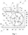
- Fig. 1 shows a conveying apparatus 1 comprising a feeding apparatus 2, a transferring apparatus 3 and a receiving apparatus 4.
- the feeding apparatus 2 is adapted to feed the rod-like article 5 with the longitudinal axis X to a receiving area 6 of the transferring apparatus 3 which conveys the rod-like article 5 to a transferring area 7.
- the receiving apparatus 4 is adapted to receive the rod-like article 5 from the transferring area 7, axially one after another.
- the feeding apparatus 2 comprises a channel 8 along which the rod-like articles 5 move axially one after another in the direction T1 in a stream S1, whereas the movement of the rod-like articles 5 is accomplished by means of a spiral drum 9.
- a separating cam 10 is used to push the first rod-like article 5 into the receiving area 6, whereas the pushing and the feeding of an individual rod-like article by the feeding apparatus 2 takes place transversely to the axis X of the rod-like article 5.
- the feeding apparatus 2 is adapted to feed the rod-like article 5 so that the rod-like article is placed tangentially to the circular movement of a lug 15 on the transferring apparatus 3.
- the rod-like article 5 may be fed transversely to the axis X with a zero velocity in the tangential direction to the path of movement of the rod-like article 5 on the transferring apparatus 3.
- the rod-like article 5 may be fed with a certain velocity v1 in the tangential direction to the path of movement on the transferring apparatus 3, whereas the velocity v1 in the tangential direction constitutes the initial velocity of the rod-like article 5 for the movement on the path of movement, and its value stands at between 0 and 4 m/s.
- the feeding apparatus 2 may also have the form of a vertical channel in which the rod-like articles 5 which are fed one by one to the receiving area 6 are collected; in such case the initial velocity amounts to zero.
- the receiving apparatus 4 is a belt conveyor provided with a belt 4A which conveys the rod-like articles 5 in the direction T2 in a stream S2 at equal distances.
- the receiving apparatus 4 may have the form of a conveying disc with lugs.
- the velocity v2 with which the rod-like article 5 moves in the transferring area 7 and on the receiving apparatus 4 is several times greater than the initial velocity v1, whereas the value of the velocity v2 stands at between 8 and 12 m/s.
- the velocity of the rod-like article 5 is increased from the velocity v1 equal to 2 m/s to the velocity v2 equal to 10 m/s.
- the transferring apparatus 3 is provided with a rotatable disc 11 with the axis of rotation Y having the circumferential surface 12, whereas the disc 11 rotates with a constant speed ⁇ .
- the transferring apparatus 3 is provided with the lugs 15, rotatably attached to the disc 11 by means of a double-arm lever 13 and actuated by means of a drive mechanism 20.
- the double-arm lever 13 is rotatably attached on the axis Z, whereas the lug 15 is attached to the double-arm lever 13 on its longer arm 14, and the shorter arm 16 of the double-arm lever 13 is provided with a rotatably attached roller 17 rolling on the cam 19 of the drive mechanism 20.
- the lug 15 is used to convey the rod-like article 5 around or on the circumferential surface 12 in a conveying channel 18.
- the roller 17 mates with the cam 19 attached fixedly, centrally to the rotatable disc 11.
- the arms 14 and 16 of the lever 13 may be equal, however, preferably the arm 14 carrying the lug 15 is longer than the arm 16 carrying the roller 17, preferably 2 times longer, more preferably more than 3 times longer.
- the cam 19 together with the roller 17 and the arms 14 and 16 of the lever 13 constitute the drive mechanism 20 designed to shift the lugs 15 relative to the surface of the rotatable disc 11.
- the lug 15 moves on the movement path 21 and is adapted to convey the rod-like article 5 in the conveying channel 18, from the feeding apparatus 2 to the receiving apparatus 4.
- the movement path 21 has two parts, the first part 21A of the path 21 runs from the rod-like article receiving area 6 to the rod-like article transferring area 7, the second part 21B of the movement path 21 runs from the rod-like article transferring area 7 to the rod-like article receiving area 6.
- the rod-like article 5 begins its movement in the part 21A of the path 21, while in the transferring area 7 the rod-like article 5 ends its movement in the part 21A, with the drive mechanism being adapted so that the lug 15 reduces the speed at least in the part of the movement path 21 before the receiving area 6, i.e.
- the cam 19 is designed so that in the receiving area 6 the lug 15 moves with a minimum speed, while a reduction of the speed of the lug 15 takes place at least before the receiving area 6, precisely before the moment of commencement of the movement by the rod-like article 5 in the receiving area 6.
- the transferring velocity i.e. the velocity required in the transferring area 7 may be achieved only in a certain fragment of the part 21A.
- the rod-like article 5 initially increases its velocity to the maximum velocity required in the receiving apparatus 4, and then moves further witch such velocity up to the transferring area 7.
- the increase of the velocity of the rod-like article 5 to the transferring velocity may take place in the entire part 21A.
- the rod-like article 5 increases its velocity at a uniform rate on the entire way from the receiving area 6 to the transferring area 7.
- the double-arm lever 13 is attached rotatably relative to the disc 11.
- the cam 19 forces a clockwise rotation of the lever 13 relative to the disc 11. Once the lug 15 has passed through the transferring area 7, the lug 15 moves in the part 21B, whereas at the end of the part 21B the speed of the lug 15 must be reduced to the minimum.
- the cam 19 may be designed so that the speed of the lug 15 is reduced continuously.
- the drive mechanism 20 may be additionally adapted to increase the speed of the lug 15, at least in the part 21B of the path 21, between the area 7 for transferring the rod-like article 4 to the receiving apparatus 4 and the area 6 for receiving the rod-like article 5 from the feeding apparatus 2, i.e.
- the cam 19 may be also designed so that initially the speed of the lug 15 increases in the part 21B, and then decreases to the minimum in the receiving area 6. In order to reduce the speed of thee lug 15, the cam 19 forces an anticlockwise rotation of the lever 13 relative to the disc 11.
- Fig. 2 shows a second embodiment of the conveying apparatus 1', similar to the first embodiment, where the rod-like articles 5' with a greater length are conveyed.
- the transferring apparatus 3' is provided with the lugs 15 moving on the path 21.
- the levers 13 mating with the cam 19' are attached rotatably relatively to the disc 11' with a smaller diameter than in the first embodiment, the disc 11' rotates with a constant speed ⁇ .
- the shape of the cam 19' was adapted to the greater length of the rod-like article 5', it was taken into consideration that the speed of the lug needs to be reduced earlier in the part 21B in order to achieve the minimum speed earlier.
- a stationary guide 22 having a circumferential surface 23 on which the rod-like articles 5' move.
- the drive mechanism is provided with an electric drive with a linear electromagnetic motor.
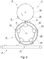
- the feeding apparatus 2' has the form of a rotatable disc 24 provided with the lugs 25 fixedly attached to the disc 24.
- the feeding apparatus feeds the rod-like articles 5 axially and tangentially to the movement path of the rod-like article 5 in the receiving area 6 on the transferring apparatus 3".
- the transferring apparatus 3" is provided with the lugs 15'.
- the lugs 15' are attached to drive carriages 26 which have an electromagnetic drive and move on a track 27 with an oval shape, on a stationary guide 22 in such a way as if they were attached rotatably relative to the axis Y.
- the electric drive is adapted to actuate the drive carriage 26 with a variable speed as described for the first and second embodiments.
- the acceleration of the carriage, maintaining the speed of the carriage at a constant level and the deceleration of the carriage take place by means of an electromagnetic drive controller.
- Fig. 4 shows an embodiment of an individual lug 15" which may be used in the conveying apparatus.
- the drive mechanism is provided with a gearwheel 28, rotatably attached on the axis Y.
- a planet gear 30 which is geared and is mating with the gear wheel 28 is attached to the rotatable arm 29 also on the axis Y.
- the gear wheel 28 moving with the speed ⁇ 1 has a drive which is independent of the drive of the arm 29 moving with the speed ⁇ 2 and carrying the planet gear 30 (the drives of the gears were not shown).
- the lug 15" is attached to the planet gear 30.
- the speed of the lug 15" is controlled by changing the angular speeds ⁇ 1 and ⁇ 2.
- the speed of the lug 15" is reduced either by reducing the speed ⁇ 2 or by increasing the speed ⁇ 1, in each case the lug 15" will turn with the speed ⁇ 3 so that the lug 15" will reduce its speed (in the drawing, it will deviate to the left).
- a reverse change of the speeds ⁇ 1 and ⁇ 2 needs to be made.
- the drive mechanism is provided with a flexible bracket 31 of the lug 15"', rotatably attached on the axis Y and an arm 32 provided with support elements 33 comprising the flexible bracket 31.
- the flexible bracket 31 has, for example, the form of a flat spring.
- an arm 32 having support elements 33 which comprise, on both sides, the flexible bracket 31.
- the flexible bracket 31 moving with the speed ⁇ 1 has a drive which is independent of the drive of the arm 32 moving with the speed ⁇ 2 (the drives were not shown).
- the speed of the lug 15'" is controlled by changing the angular speeds ⁇ 1 and ⁇ 2.
- the object of the invention is also a method for conveying the rod-like articles 5, 5' from the rod-like article feeding apparatus 2, 2' through the rod-like article transferring apparatus 3, 3', 3" to the receiving apparatus 4.
- the rod-like article is fed from the feeding apparatus 2, 2' to the transferring apparatus 3, 3', 3"
- the rod-like article is transferred on a circular path of movement by means of the transferring apparatus 3, 3', 3" provided with the lugs 15.
- the rod-like article is transferred from the transferring apparatus 3, 3', 3" to the receiving apparatus 4 adapted to convey the rod-like articles one after another.
- the rod-like article is fed to the transferring disc transversely to the axis of the rod-like article.
- the rod-like article is fed to the transferring disc tangentially to the axis of the rod-like article.
- the rod-like articles are conveyed at equal distances on the receiving apparatus 4.
Landscapes
- Engineering & Computer Science (AREA)
- Mechanical Engineering (AREA)
- Manufacturing Of Cigar And Cigarette Tobacco (AREA)
- Cigarettes, Filters, And Manufacturing Of Filters (AREA)
- Specific Conveyance Elements (AREA)
Claims (17)
- Die Vorrichtung (1, 1', 1") zum Fördern von stabförmigen Gegenständen der Tabakindustrie, umfassend
die Zuführvorrichtung (2, 2') von stabförmigen Gegenständen (5, 5') geeignet ist, zu einem Aufnahmebereich (6) einer Übertragungseinheit (3, 3', 3"),
die Übertragungseinheit (3, 3', 3") mit Nasen (15, 15'), die sich auf einer Kreisbahn bewegen und dazu geeignet sind, einen stabförmigen Gegenstand (5, 5') aus der Zuführvorrichtung (2, 2') zur Empfangsvorrichtung (4), die drehbare Nase (15, 15'), die relativ zu einer drehbaren Scheibe (11, 11') angebracht ist, und mittels eines Antriebsmechanismus (20, 20') betätigt; der Bewegungsweg (21) der Nase (15, 15'), der durch den Bereich (6) verläuft, um den stabförmigen Gegenstand (5, 5') von der Zuführvorrichtung (2, 2') aufzunehmen und einen Bereich (7) zum Übertragen des stabförmigen Gegenstands (5, 5') auf die Empfangsvorrichtung (4),
und die Empfangsvorrichtung (4), die dazu ausgelegt ist, die stabförmigen Gegenstände (5, 5') nacheinander axial zu befördern,
ist dadurch gekennzeichnet, dass
der Antriebsmechanismus (20, 20') so angepasst ist, dass die Nase (15, 15') die Geschwindigkeit zumindest in einem Teil (21B) des Bewegungsweges (21) vor dem Bereich (6) und verringert / oder in dem Bereich (6) zum Aufnehmen des stabförmigen Gegenstands (5, 5') von der Zuführvorrichtung (2, 2') zur Übergabevorrichtung (3, 3') und erhöht die Geschwindigkeit zumindest teilweise (21A) des Bewegungsweges (21) zwischen dem Bereich (6) zum Aufnehmen des stabförmigen Gegenstands (5, 5') von der Zuführvorrichtung (2, 2') und dem Bereich (7) zum Übertragen des stabförmigen Gegenstands (5, 5') an die Empfangsvorrichtung (4). - Die Vorrichtung nach Anspruch 1 ist dadurch gekennzeichnet, dass der Antriebsmechanismus (20, 20') zusätzlich so angepasst ist, dass die Nase (15, 15') die Geschwindigkeit zumindest in einem Teil (21B) des Bewegungsweges (21) zwischen dem Bereich (7) zum Übertragen des stabförmigen Gegenstands (5, 5') zur Empfangsvorrichtung (4) und dem Bereich (6) zum Aufnehmen des stabförmigen Gegenstands (5, 5') von der Zufuhrvorrichtung (2, 2') erhöht.
- Die Vorrichtung nach Anspruch 1 oder 2 ist dadurch gekennzeichnet, dass der Antriebsmechanismus (20, 20') mit einem Nocken (19, 19') und einem Doppelarmhebel (13) versehen ist, der drehbar relativ zu der drehbaren Scheibe (11, 11') angebracht ist,
zusätzlich ist die Nase (15, 15') am Doppelarmhebel (13), an seinem längeren Arm (14) und am kürzeren Arm (16) des Doppelarmhebels (13) angebracht ist mit einer Rolle (17) versehen, die auf dem Nocken (19, 19') des Antriebsmechanismus (20, 20') rollt, während der längere Arm (14) des Doppelarmhebels (13) a aufweist erheblich länger als der kürzere Arm (16) des Doppelarmhebels (13). - Die Vorrichtung nach Anspruch 3 ist dadurch gekennzeichnet, dass das Verhältnis der Länge des längeren Arms (14) des Doppelarmhebels (13) zum kürzeren Arm (16) des Doppelarmhebels (13) größer als 2:1, vorzugsweise größer als 3:1, ist.
- Die Vorrichtung nach Anspruch 1 ist dadurch gekennzeichnet, dass der Antriebsmechanismus mit einem elektrischen Antrieb mit einem linearen elektromagnetischen Motor versehen ist, dessen Spur (27) eine ovale Form hat, und Antriebsschlitten (26), die sich entlang der Spur (27) bewegen,
zusätzlich ist die Nase (15') an dem Antriebsschlitten (26) angebracht, während der elektrische Antrieb dazu ausgelegt ist, den Antriebsschlitten (26) mit einer variablen Geschwindigkeit zu betätigen. - Die Vorrichtung nach Anspruch 1 oder 2 ist dadurch gekennzeichnet, dass der Antriebsmechanismus (20, 20') mit einem Zahnrad (28) und einem Zahnrad (30) versehen ist, die an dem drehbaren Arm (29), der Nase (15") am Zahnrad (30) angebracht sind, wobei der Arm (29) und das Zahnrad (28) unabhängige Antriebe haben.
- Die Vorrichtung nach Anspruch 1 oder 2 ist dadurch gekennzeichnet, dass der Antriebsmechanismus mit einer flexiblen Halterung (31) und einem Arm (32) versehen ist, die mit Stützelementen (33) versehen sind, die die flexible Halterung (31) umfassen, während die Nase (15") ist an der flexiblen Halterung (31) angebracht, und die flexible Halterung (31) und der Arm (32) haben unabhängige Antriebe.
- Die Vorrichtung nach einem der Ansprüche 1 bis 7 ist dadurch gekennzeichnet, dass die Zuführvorrichtung (2) dazu ausgelegt ist, den stabförmigen Gegenstand (5, 5') quer zur Achse (X) des stabförmigen Gegenstands (5, 5') zuzuführen.
- Die Vorrichtung nach Anspruch 8 ist dadurch gekennzeichnet, dass die Zuführvorrichtung (2) mit einem Trennnocken (10) versehen ist, der zum Zuführen des stabförmigen Gegenstands (5, 5') ausgelegt ist.
- Die Vorrichtung nach einem der Ansprüche 1 bis 7 ist dadurch gekennzeichnet, dass die Zuführvorrichtung (2') dazu ausgelegt ist, den stabförmigen Gegenstand (5, 5') tangential zum kreisförmigen Bewegungsweg (21) der Nase (15') an der Übertragungsvorrichtung (3") zugeführt wird.
- Die Vorrichtung nach einem der Ansprüche 1 bis 10 ist dadurch gekennzeichnet, dass die Empfangsvorrichtung ein Förderband ist.
- Die Vorrichtung nach einem der Ansprüche 1 bis 10 ist dadurch gekennzeichnet ist, dass die Empfangsvorrichtung eine Förderscheibe (24) mit Nasen (25) ist.
- Die Vorrichtung nach einem der Ansprüche 1 bis 12, die dadurch gekennzeichnet ist, dass die Empfangsvorrichtung (4) dazu ausgelegt ist, die stabförmigen Gegenstände in gleichen Abständen zu befördern.
- Das Verfahren zum Fördern eines stabförmigen Gegenstands der Tabakindustrie von einer stabförmigen Artikelzufuhrvorrichtung durch eine Vorrichtung, die einen stabförmigen Gegenstand zu einer Empfangsvorrichtung überträgt, in der
dem stabförmige Gegenstand von der Zufuhrvorrichtung zur Übergabevorrichtung zugeführt wird,
der stabförmige Gegenstand wird mittels der mit Nasen versehenen Übertragungsvorrichtung auf eine kreisförmige Bewegungsbahn übertragen,
der stabförmige Gegenstand wird von der Übertragungsvorrichtung auf die Aufnahmevorrichtung übertragen, die dazu ausgelegt ist, die stabförmigen Gegenstände axial nacheinander zu befördern,
ist dadurch gekennzeichnet, dass
beim Fördern des stabförmigen Gegenstands in der Übertragungsvorrichtung die Geschwindigkeit des stabförmigen Gegenstands zwischen einem Bereich zum Aufnehmen eines stabförmigen Gegenstands von der Zuführvorrichtung und dem Bereich zum Übertragen des stabförmigen Gegenstands zum Empfangsvorrichtung. - Das Verfahren nach Anspruch 14 ist dadurch gekennzeichnet, dass der stabförmige Gegenstand der Übertragungsscheibe quer zur Achse des stabförmigen Gegenstands zugeführt wird.
- Das Verfahren nach Anspruch 14 ist dadurch gekennzeichnet, dass der stabförmige Gegenstand der Übertragungsscheibe indirekt zur Achse des stabförmigen Gegenstands zugeführt wird.
- Das Verfahren nach einem der Ansprüche 14 bis 16 ist das dadurch gekennzeichnet, dass die stabförmigen Gegenstände in der Empfangsvorrichtung in gleichen Abständen befördert werden.
Priority Applications (9)
| Application Number | Priority Date | Filing Date | Title |
|---|---|---|---|
| EP18165763.6A EP3549458B1 (de) | 2018-04-04 | 2018-04-04 | Verfahren und vorrichtung zum fördern von stabförmigen artikeln der tabakindustrie |
| HUE18165763A HUE053474T2 (hu) | 2018-04-04 | 2018-04-04 | Eljárás és berendezés dohányipari rúd-szerû árucikkek szállítására |
| PL18165763T PL3549458T3 (pl) | 2018-04-04 | 2018-04-04 | Sposób i urządzenie do transportowania artykułów prętopodobnych przemysłu tytoniowego |
| JP2019051777A JP6978460B2 (ja) | 2018-04-04 | 2019-03-19 | タバコ産業用ロッド状物品の搬送方法及び装置 |
| RU2019108179A RU2734602C1 (ru) | 2018-04-04 | 2019-03-21 | Способ и устройство для перемещения стержнеобразных изделий табачной промышленности |
| US16/363,306 US11219238B2 (en) | 2018-04-04 | 2019-03-25 | Method and apparatus for conveying rod-like articles of tobacco industry |
| CN201910227709.8A CN110338453B (zh) | 2018-04-04 | 2019-03-25 | 用于传送烟草业的杆状物品的方法和设备 |
| KR1020190034521A KR102467040B1 (ko) | 2018-04-04 | 2019-03-26 | 담배 산업의 로드형 제품들의 이송 방법 및 장치 |
| BR102019006803-5A BR102019006803B1 (pt) | 2018-04-04 | 2019-04-03 | Aparelho e método para transportar artigos similares a hastes da indústria de tabaco |
Applications Claiming Priority (1)
| Application Number | Priority Date | Filing Date | Title |
|---|---|---|---|
| EP18165763.6A EP3549458B1 (de) | 2018-04-04 | 2018-04-04 | Verfahren und vorrichtung zum fördern von stabförmigen artikeln der tabakindustrie |
Publications (2)
| Publication Number | Publication Date |
|---|---|
| EP3549458A1 EP3549458A1 (de) | 2019-10-09 |
| EP3549458B1 true EP3549458B1 (de) | 2020-12-02 |
Family
ID=62245119
Family Applications (1)
| Application Number | Title | Priority Date | Filing Date |
|---|---|---|---|
| EP18165763.6A Active EP3549458B1 (de) | 2018-04-04 | 2018-04-04 | Verfahren und vorrichtung zum fördern von stabförmigen artikeln der tabakindustrie |
Country Status (8)
| Country | Link |
|---|---|
| US (1) | US11219238B2 (de) |
| EP (1) | EP3549458B1 (de) |
| JP (1) | JP6978460B2 (de) |
| KR (1) | KR102467040B1 (de) |
| CN (1) | CN110338453B (de) |
| HU (1) | HUE053474T2 (de) |
| PL (1) | PL3549458T3 (de) |
| RU (1) | RU2734602C1 (de) |
Families Citing this family (1)
| Publication number | Priority date | Publication date | Assignee | Title |
|---|---|---|---|---|
| CN115959463B (zh) * | 2022-12-02 | 2025-12-19 | 西南石油大学 | 一种高处坠落物防冲击保护传递方法 |
Family Cites Families (15)
| Publication number | Priority date | Publication date | Assignee | Title |
|---|---|---|---|---|
| US3010561A (en) * | 1957-12-26 | 1961-11-28 | Koerber & Co Kg | Filter mouthpiece cigarette making machines |
| GB915203A (en) * | 1958-02-27 | 1963-01-09 | Desmond Walter Molins | Improvements in or relating to the manufacture of composite mouthpieces for cigarettes |
| IT1304022B1 (it) * | 1998-07-06 | 2001-03-02 | Gd Spa | Unita' per l'alimentazione di sbozzati in una macchinaimpacchettatrice. |
| DE10146992A1 (de) | 2001-09-18 | 2003-04-03 | Hauni Maschinenbau Ag | Übergabeeinrichtung und Muldentrommel sowie Verfahren zur Übergabe von Hartfilterlementen |
| US7165668B2 (en) * | 2003-10-21 | 2007-01-23 | Hauni Maschinenbau Ag | Apparatus and method for the delivery of rod-shaped articles |
| WO2006004111A1 (ja) | 2004-07-07 | 2006-01-12 | Japan Tobacco Inc. | フィルタロッドの製造機 |
| DE102007028478B4 (de) | 2007-06-18 | 2015-03-05 | Hauni Maschinenbau Ag | Empfangsvorrichtung und Förderverfahren |
| PL383995A1 (pl) * | 2007-12-10 | 2009-06-22 | Philip Morris Products S.A. | Sposób zestawiania grup segmentów w procesie wytwarzania filtrów wielosegmentowych oraz urządzenie do przygotowywania i zestawiania w grupy segmentów w procesie wytwarzania filtrów wielosegmentowych |
| PL210818B1 (pl) * | 2008-05-16 | 2012-03-30 | Int Tobacco Machinery Poland | Zespół magazynująco-transportowy dla podłużnych elementów prętopodobnych, jak również sposób sterowania przepływem masowym oraz napełniania i opróżniania zespołu magazynująco-transportowego dla podłużnych elementów prętopodobnych |
| PL215734B1 (pl) | 2009-08-14 | 2014-01-31 | Int Tobacco Machinery Poland | Urzadzenie magazynujaco-transportowe dla podluznych elementów pretopodobnych |
| ITBO20110158A1 (it) * | 2011-03-28 | 2012-09-29 | Gd Spa | Tamburo di trasferimento o di accompagnamento per spezzoni di filtro o di sigaretta con teste operative portate da bracci radiali. |
| DE102012201927B3 (de) * | 2012-02-09 | 2013-06-06 | Hauni Maschinenbau Ag | Längsförderer für stabförmige Produkte der Tabak verarbeitenden Industrie |
| PL409093A1 (pl) * | 2014-08-04 | 2016-02-15 | International Tobacco Machinery Poland Spółka Z Ograniczoną Odpowiedzialnością | Sposób i urządzenie do transferowania elementów prętopodobnych w maszynach przemysłu tytoniowego |
| PL3117722T3 (pl) | 2015-07-16 | 2018-01-31 | Int Tobacco Machinery Poland Sp Zoo | Tarcza transferowa i jej zastosowanie |
| HUE036621T2 (hu) * | 2015-10-21 | 2018-07-30 | Int Tobacco Machinery Poland Sp Zoo | Rúd alakú árucikk szállítására szolgáló szállítási eljárás és szállító berendezés |
-
2018
- 2018-04-04 EP EP18165763.6A patent/EP3549458B1/de active Active
- 2018-04-04 PL PL18165763T patent/PL3549458T3/pl unknown
- 2018-04-04 HU HUE18165763A patent/HUE053474T2/hu unknown
-
2019
- 2019-03-19 JP JP2019051777A patent/JP6978460B2/ja active Active
- 2019-03-21 RU RU2019108179A patent/RU2734602C1/ru active
- 2019-03-25 CN CN201910227709.8A patent/CN110338453B/zh active Active
- 2019-03-25 US US16/363,306 patent/US11219238B2/en not_active Expired - Fee Related
- 2019-03-26 KR KR1020190034521A patent/KR102467040B1/ko active Active
Non-Patent Citations (1)
| Title |
|---|
| None * |
Also Published As
| Publication number | Publication date |
|---|---|
| US20190307162A1 (en) | 2019-10-10 |
| HUE053474T2 (hu) | 2021-06-28 |
| RU2734602C1 (ru) | 2020-10-21 |
| JP6978460B2 (ja) | 2021-12-08 |
| US11219238B2 (en) | 2022-01-11 |
| BR102019006803A2 (pt) | 2019-10-22 |
| KR102467040B1 (ko) | 2022-11-11 |
| EP3549458A1 (de) | 2019-10-09 |
| CN110338453B (zh) | 2022-01-18 |
| CN110338453A (zh) | 2019-10-18 |
| KR20190116064A (ko) | 2019-10-14 |
| JP2019180397A (ja) | 2019-10-24 |
| PL3549458T3 (pl) | 2021-06-14 |
Similar Documents
| Publication | Publication Date | Title |
|---|---|---|
| CN1608530B (zh) | 用于棒形物品传输的装置和方法 | |
| CN115515440A (zh) | 烟草加工业的输送滚筒 | |
| US10653176B2 (en) | Apparatus for manufacturing of multi-element rods of tobacco industry | |
| EP3322309B1 (de) | Verfahren und vorrichtung zur verschiebung von stabförmigen artikeln und vorrichtung zur verschiebung von stabförmigen artikeln | |
| US11219238B2 (en) | Method and apparatus for conveying rod-like articles of tobacco industry | |
| EP2736358B1 (de) | Fördervorrichtung und verfahren zum fördern von gegenständen | |
| EP3629780B1 (de) | Übertragungsvorrichtung zur übertragung und verfahren zur übertragung von stabförmigen artikeln der tabakindustrie sowie vorrichtung zur umwandlung der konfiguration eines stroms solcher artikel | |
| EP3849348B1 (de) | Vorrichtung zum überführen von stabförmigen artikeln der tabakverarbeitenden industrie | |
| EP3158879B2 (de) | Übertragungsverfahren und übertragungsvorrichtung zur übertragung von stäbchenförmigem artikel | |
| US20190183164A1 (en) | Apparatus for manufacturing of multi-element rods of tobacco industry | |
| US20260130410A1 (en) | Apparatus for pushing together rod-like articles of tobacco industry | |
| WO2024246676A1 (en) | Apparatus for pushing together rod-like articles of tobacco industry | |
| BR102019006803B1 (pt) | Aparelho e método para transportar artigos similares a hastes da indústria de tabaco | |
| CN105795510B (zh) | 烟草加工行业的输送滚筒 | |
| PL242031B1 (pl) | Sposób i urządzenie do transportowania artykułów prętopodobnych przemysłu tytoniowego | |
| CN1276188A (zh) | 滚卷杆形件的设备 | |
| ITBO940449A1 (it) | Macchina operatrice continua per sigarette. |
Legal Events
| Date | Code | Title | Description |
|---|---|---|---|
| PUAI | Public reference made under article 153(3) epc to a published international application that has entered the european phase |
Free format text: ORIGINAL CODE: 0009012 |
|
| STAA | Information on the status of an ep patent application or granted ep patent |
Free format text: STATUS: THE APPLICATION HAS BEEN PUBLISHED |
|
| AK | Designated contracting states |
Kind code of ref document: A1 Designated state(s): AL AT BE BG CH CY CZ DE DK EE ES FI FR GB GR HR HU IE IS IT LI LT LU LV MC MK MT NL NO PL PT RO RS SE SI SK SM TR |
|
| AX | Request for extension of the european patent |
Extension state: BA ME |
|
| STAA | Information on the status of an ep patent application or granted ep patent |
Free format text: STATUS: REQUEST FOR EXAMINATION WAS MADE |
|
| 17P | Request for examination filed |
Effective date: 20200409 |
|
| RBV | Designated contracting states (corrected) |
Designated state(s): AL AT BE BG CH CY CZ DE DK EE ES FI FR GB GR HR HU IE IS IT LI LT LU LV MC MK MT NL NO PL PT RO RS SE SI SK SM TR |
|
| GRAP | Despatch of communication of intention to grant a patent |
Free format text: ORIGINAL CODE: EPIDOSNIGR1 |
|
| STAA | Information on the status of an ep patent application or granted ep patent |
Free format text: STATUS: GRANT OF PATENT IS INTENDED |
|
| GRAJ | Information related to disapproval of communication of intention to grant by the applicant or resumption of examination proceedings by the epo deleted |
Free format text: ORIGINAL CODE: EPIDOSDIGR1 |
|
| STAA | Information on the status of an ep patent application or granted ep patent |
Free format text: STATUS: REQUEST FOR EXAMINATION WAS MADE |
|
| INTG | Intention to grant announced |
Effective date: 20200727 |
|
| INTC | Intention to grant announced (deleted) | ||
| GRAP | Despatch of communication of intention to grant a patent |
Free format text: ORIGINAL CODE: EPIDOSNIGR1 |
|
| STAA | Information on the status of an ep patent application or granted ep patent |
Free format text: STATUS: GRANT OF PATENT IS INTENDED |
|
| GRAS | Grant fee paid |
Free format text: ORIGINAL CODE: EPIDOSNIGR3 |
|
| GRAA | (expected) grant |
Free format text: ORIGINAL CODE: 0009210 |
|
| STAA | Information on the status of an ep patent application or granted ep patent |
Free format text: STATUS: THE PATENT HAS BEEN GRANTED |
|
| INTG | Intention to grant announced |
Effective date: 20201013 |
|
| AK | Designated contracting states |
Kind code of ref document: B1 Designated state(s): AL AT BE BG CH CY CZ DE DK EE ES FI FR GB GR HR HU IE IS IT LI LT LU LV MC MK MT NL NO PL PT RO RS SE SI SK SM TR |
|
| REG | Reference to a national code |
Ref country code: GB Ref legal event code: FG4D |
|
| REG | Reference to a national code |
Ref country code: AT Ref legal event code: REF Ref document number: 1339903 Country of ref document: AT Kind code of ref document: T Effective date: 20201215 Ref country code: CH Ref legal event code: EP |
|
| REG | Reference to a national code |
Ref country code: IE Ref legal event code: FG4D |
|
| REG | Reference to a national code |
Ref country code: DE Ref legal event code: R096 Ref document number: 602018010245 Country of ref document: DE |
|
| REG | Reference to a national code |
Ref country code: CH Ref legal event code: NV Representative=s name: VALIPAT S.A. C/O BOVARD SA NEUCHATEL, CH |
|
| PG25 | Lapsed in a contracting state [announced via postgrant information from national office to epo] |
Ref country code: RS Free format text: LAPSE BECAUSE OF FAILURE TO SUBMIT A TRANSLATION OF THE DESCRIPTION OR TO PAY THE FEE WITHIN THE PRESCRIBED TIME-LIMIT Effective date: 20201202 Ref country code: FI Free format text: LAPSE BECAUSE OF FAILURE TO SUBMIT A TRANSLATION OF THE DESCRIPTION OR TO PAY THE FEE WITHIN THE PRESCRIBED TIME-LIMIT Effective date: 20201202 Ref country code: NO Free format text: LAPSE BECAUSE OF FAILURE TO SUBMIT A TRANSLATION OF THE DESCRIPTION OR TO PAY THE FEE WITHIN THE PRESCRIBED TIME-LIMIT Effective date: 20210302 Ref country code: GR Free format text: LAPSE BECAUSE OF FAILURE TO SUBMIT A TRANSLATION OF THE DESCRIPTION OR TO PAY THE FEE WITHIN THE PRESCRIBED TIME-LIMIT Effective date: 20210303 |
|
| REG | Reference to a national code |
Ref country code: NL Ref legal event code: MP Effective date: 20201202 |
|
| REG | Reference to a national code |
Ref country code: AT Ref legal event code: MK05 Ref document number: 1339903 Country of ref document: AT Kind code of ref document: T Effective date: 20201202 |
|
| PG25 | Lapsed in a contracting state [announced via postgrant information from national office to epo] |
Ref country code: LV Free format text: LAPSE BECAUSE OF FAILURE TO SUBMIT A TRANSLATION OF THE DESCRIPTION OR TO PAY THE FEE WITHIN THE PRESCRIBED TIME-LIMIT Effective date: 20201202 Ref country code: SE Free format text: LAPSE BECAUSE OF FAILURE TO SUBMIT A TRANSLATION OF THE DESCRIPTION OR TO PAY THE FEE WITHIN THE PRESCRIBED TIME-LIMIT Effective date: 20201202 |
|
| REG | Reference to a national code |
Ref country code: HU Ref legal event code: AG4A Ref document number: E053474 Country of ref document: HU |
|
| PG25 | Lapsed in a contracting state [announced via postgrant information from national office to epo] |
Ref country code: HR Free format text: LAPSE BECAUSE OF FAILURE TO SUBMIT A TRANSLATION OF THE DESCRIPTION OR TO PAY THE FEE WITHIN THE PRESCRIBED TIME-LIMIT Effective date: 20201202 Ref country code: NL Free format text: LAPSE BECAUSE OF FAILURE TO SUBMIT A TRANSLATION OF THE DESCRIPTION OR TO PAY THE FEE WITHIN THE PRESCRIBED TIME-LIMIT Effective date: 20201202 |
|
| REG | Reference to a national code |
Ref country code: LT Ref legal event code: MG9D |
|
| PG25 | Lapsed in a contracting state [announced via postgrant information from national office to epo] |
Ref country code: LT Free format text: LAPSE BECAUSE OF FAILURE TO SUBMIT A TRANSLATION OF THE DESCRIPTION OR TO PAY THE FEE WITHIN THE PRESCRIBED TIME-LIMIT Effective date: 20201202 Ref country code: SK Free format text: LAPSE BECAUSE OF FAILURE TO SUBMIT A TRANSLATION OF THE DESCRIPTION OR TO PAY THE FEE WITHIN THE PRESCRIBED TIME-LIMIT Effective date: 20201202 Ref country code: RO Free format text: LAPSE BECAUSE OF FAILURE TO SUBMIT A TRANSLATION OF THE DESCRIPTION OR TO PAY THE FEE WITHIN THE PRESCRIBED TIME-LIMIT Effective date: 20201202 Ref country code: PT Free format text: LAPSE BECAUSE OF FAILURE TO SUBMIT A TRANSLATION OF THE DESCRIPTION OR TO PAY THE FEE WITHIN THE PRESCRIBED TIME-LIMIT Effective date: 20210405 Ref country code: SM Free format text: LAPSE BECAUSE OF FAILURE TO SUBMIT A TRANSLATION OF THE DESCRIPTION OR TO PAY THE FEE WITHIN THE PRESCRIBED TIME-LIMIT Effective date: 20201202 Ref country code: CZ Free format text: LAPSE BECAUSE OF FAILURE TO SUBMIT A TRANSLATION OF THE DESCRIPTION OR TO PAY THE FEE WITHIN THE PRESCRIBED TIME-LIMIT Effective date: 20201202 Ref country code: EE Free format text: LAPSE BECAUSE OF FAILURE TO SUBMIT A TRANSLATION OF THE DESCRIPTION OR TO PAY THE FEE WITHIN THE PRESCRIBED TIME-LIMIT Effective date: 20201202 |
|
| PG25 | Lapsed in a contracting state [announced via postgrant information from national office to epo] |
Ref country code: AT Free format text: LAPSE BECAUSE OF FAILURE TO SUBMIT A TRANSLATION OF THE DESCRIPTION OR TO PAY THE FEE WITHIN THE PRESCRIBED TIME-LIMIT Effective date: 20201202 |
|
| REG | Reference to a national code |
Ref country code: DE Ref legal event code: R097 Ref document number: 602018010245 Country of ref document: DE |
|
| PG25 | Lapsed in a contracting state [announced via postgrant information from national office to epo] |
Ref country code: IS Free format text: LAPSE BECAUSE OF FAILURE TO SUBMIT A TRANSLATION OF THE DESCRIPTION OR TO PAY THE FEE WITHIN THE PRESCRIBED TIME-LIMIT Effective date: 20210402 |
|
| PLBE | No opposition filed within time limit |
Free format text: ORIGINAL CODE: 0009261 |
|
| STAA | Information on the status of an ep patent application or granted ep patent |
Free format text: STATUS: NO OPPOSITION FILED WITHIN TIME LIMIT |
|
| PG25 | Lapsed in a contracting state [announced via postgrant information from national office to epo] |
Ref country code: AL Free format text: LAPSE BECAUSE OF FAILURE TO SUBMIT A TRANSLATION OF THE DESCRIPTION OR TO PAY THE FEE WITHIN THE PRESCRIBED TIME-LIMIT Effective date: 20201202 |
|
| 26N | No opposition filed |
Effective date: 20210903 |
|
| PG25 | Lapsed in a contracting state [announced via postgrant information from national office to epo] |
Ref country code: DK Free format text: LAPSE BECAUSE OF FAILURE TO SUBMIT A TRANSLATION OF THE DESCRIPTION OR TO PAY THE FEE WITHIN THE PRESCRIBED TIME-LIMIT Effective date: 20201202 Ref country code: SI Free format text: LAPSE BECAUSE OF FAILURE TO SUBMIT A TRANSLATION OF THE DESCRIPTION OR TO PAY THE FEE WITHIN THE PRESCRIBED TIME-LIMIT Effective date: 20201202 Ref country code: MC Free format text: LAPSE BECAUSE OF FAILURE TO SUBMIT A TRANSLATION OF THE DESCRIPTION OR TO PAY THE FEE WITHIN THE PRESCRIBED TIME-LIMIT Effective date: 20201202 |
|
| PG25 | Lapsed in a contracting state [announced via postgrant information from national office to epo] |
Ref country code: LU Free format text: LAPSE BECAUSE OF NON-PAYMENT OF DUE FEES Effective date: 20210404 |
|
| REG | Reference to a national code |
Ref country code: BE Ref legal event code: MM Effective date: 20210430 |
|
| PG25 | Lapsed in a contracting state [announced via postgrant information from national office to epo] |
Ref country code: FR Free format text: LAPSE BECAUSE OF NON-PAYMENT OF DUE FEES Effective date: 20210430 Ref country code: ES Free format text: LAPSE BECAUSE OF FAILURE TO SUBMIT A TRANSLATION OF THE DESCRIPTION OR TO PAY THE FEE WITHIN THE PRESCRIBED TIME-LIMIT Effective date: 20201202 |
|
| PG25 | Lapsed in a contracting state [announced via postgrant information from national office to epo] |
Ref country code: IE Free format text: LAPSE BECAUSE OF NON-PAYMENT OF DUE FEES Effective date: 20210404 |
|
| PG25 | Lapsed in a contracting state [announced via postgrant information from national office to epo] |
Ref country code: IS Free format text: LAPSE BECAUSE OF FAILURE TO SUBMIT A TRANSLATION OF THE DESCRIPTION OR TO PAY THE FEE WITHIN THE PRESCRIBED TIME-LIMIT Effective date: 20210402 |
|
| PG25 | Lapsed in a contracting state [announced via postgrant information from national office to epo] |
Ref country code: BE Free format text: LAPSE BECAUSE OF NON-PAYMENT OF DUE FEES Effective date: 20210430 |
|
| P01 | Opt-out of the competence of the unified patent court (upc) registered |
Effective date: 20230310 |
|
| PG25 | Lapsed in a contracting state [announced via postgrant information from national office to epo] |
Ref country code: CY Free format text: LAPSE BECAUSE OF FAILURE TO SUBMIT A TRANSLATION OF THE DESCRIPTION OR TO PAY THE FEE WITHIN THE PRESCRIBED TIME-LIMIT Effective date: 20201202 |
|
| PGFP | Annual fee paid to national office [announced via postgrant information from national office to epo] |
Ref country code: GB Payment date: 20230419 Year of fee payment: 6 |
|
| PG25 | Lapsed in a contracting state [announced via postgrant information from national office to epo] |
Ref country code: MK Free format text: LAPSE BECAUSE OF FAILURE TO SUBMIT A TRANSLATION OF THE DESCRIPTION OR TO PAY THE FEE WITHIN THE PRESCRIBED TIME-LIMIT Effective date: 20201202 |
|
| PG25 | Lapsed in a contracting state [announced via postgrant information from national office to epo] |
Ref country code: MT Free format text: LAPSE BECAUSE OF FAILURE TO SUBMIT A TRANSLATION OF THE DESCRIPTION OR TO PAY THE FEE WITHIN THE PRESCRIBED TIME-LIMIT Effective date: 20201202 |
|
| GBPC | Gb: european patent ceased through non-payment of renewal fee |
Effective date: 20240404 |
|
| PG25 | Lapsed in a contracting state [announced via postgrant information from national office to epo] |
Ref country code: GB Free format text: LAPSE BECAUSE OF NON-PAYMENT OF DUE FEES Effective date: 20240404 |
|
| PG25 | Lapsed in a contracting state [announced via postgrant information from national office to epo] |
Ref country code: GB Free format text: LAPSE BECAUSE OF NON-PAYMENT OF DUE FEES Effective date: 20240404 |
|
| PGFP | Annual fee paid to national office [announced via postgrant information from national office to epo] |
Ref country code: TR Payment date: 20250328 Year of fee payment: 8 |
|
| PGFP | Annual fee paid to national office [announced via postgrant information from national office to epo] |
Ref country code: DE Payment date: 20250422 Year of fee payment: 8 Ref country code: PL Payment date: 20250402 Year of fee payment: 8 |
|
| PGFP | Annual fee paid to national office [announced via postgrant information from national office to epo] |
Ref country code: HU Payment date: 20250424 Year of fee payment: 8 |
|
| PGFP | Annual fee paid to national office [announced via postgrant information from national office to epo] |
Ref country code: IT Payment date: 20250424 Year of fee payment: 8 |
|
| PGFP | Annual fee paid to national office [announced via postgrant information from national office to epo] |
Ref country code: BG Payment date: 20250424 Year of fee payment: 8 |
|
| PGFP | Annual fee paid to national office [announced via postgrant information from national office to epo] |
Ref country code: CH Payment date: 20250501 Year of fee payment: 8 |
|
| REG | Reference to a national code |
Ref country code: CH Ref legal event code: U11 Free format text: ST27 STATUS EVENT CODE: U-0-0-U10-U11 (AS PROVIDED BY THE NATIONAL OFFICE) Effective date: 20260501 |