EP3549812A1 - Système de charge et procédé de charge d'un accumulateur d'énergie électrique respectif d'une pluralité de véhicules automobiles ainsi que dispositif de charge stationnaire et véhicule automobile - Google Patents
Système de charge et procédé de charge d'un accumulateur d'énergie électrique respectif d'une pluralité de véhicules automobiles ainsi que dispositif de charge stationnaire et véhicule automobile Download PDFInfo
- Publication number
- EP3549812A1 EP3549812A1 EP19162475.8A EP19162475A EP3549812A1 EP 3549812 A1 EP3549812 A1 EP 3549812A1 EP 19162475 A EP19162475 A EP 19162475A EP 3549812 A1 EP3549812 A1 EP 3549812A1
- Authority
- EP
- European Patent Office
- Prior art keywords
- charging
- voltage
- converter
- motor vehicle
- motor vehicles
- Prior art date
- Legal status (The legal status is an assumption and is not a legal conclusion. Google has not performed a legal analysis and makes no representation as to the accuracy of the status listed.)
- Pending
Links
Images


Classifications
-
- B—PERFORMING OPERATIONS; TRANSPORTING
- B60—VEHICLES IN GENERAL
- B60L—PROPULSION OF ELECTRICALLY-PROPELLED VEHICLES; SUPPLYING ELECTRIC POWER FOR AUXILIARY EQUIPMENT OF ELECTRICALLY-PROPELLED VEHICLES; ELECTRODYNAMIC BRAKE SYSTEMS FOR VEHICLES IN GENERAL; MAGNETIC SUSPENSION OR LEVITATION FOR VEHICLES; MONITORING OPERATING VARIABLES OF ELECTRICALLY-PROPELLED VEHICLES; ELECTRIC SAFETY DEVICES FOR ELECTRICALLY-PROPELLED VEHICLES
- B60L58/00—Methods or circuit arrangements for monitoring or controlling batteries or fuel cells, specially adapted for electric vehicles
- B60L58/10—Methods or circuit arrangements for monitoring or controlling batteries or fuel cells, specially adapted for electric vehicles for monitoring or controlling batteries
- B60L58/18—Methods or circuit arrangements for monitoring or controlling batteries or fuel cells, specially adapted for electric vehicles for monitoring or controlling batteries of two or more battery modules
- B60L58/20—Methods or circuit arrangements for monitoring or controlling batteries or fuel cells, specially adapted for electric vehicles for monitoring or controlling batteries of two or more battery modules having different nominal voltages
-
- B—PERFORMING OPERATIONS; TRANSPORTING
- B60—VEHICLES IN GENERAL
- B60L—PROPULSION OF ELECTRICALLY-PROPELLED VEHICLES; SUPPLYING ELECTRIC POWER FOR AUXILIARY EQUIPMENT OF ELECTRICALLY-PROPELLED VEHICLES; ELECTRODYNAMIC BRAKE SYSTEMS FOR VEHICLES IN GENERAL; MAGNETIC SUSPENSION OR LEVITATION FOR VEHICLES; MONITORING OPERATING VARIABLES OF ELECTRICALLY-PROPELLED VEHICLES; ELECTRIC SAFETY DEVICES FOR ELECTRICALLY-PROPELLED VEHICLES
- B60L5/00—Current collectors for power supply lines of electrically-propelled vehicles
- B60L5/04—Current collectors for power supply lines of electrically-propelled vehicles using rollers or sliding shoes in contact with trolley wire
-
- B—PERFORMING OPERATIONS; TRANSPORTING
- B60—VEHICLES IN GENERAL
- B60L—PROPULSION OF ELECTRICALLY-PROPELLED VEHICLES; SUPPLYING ELECTRIC POWER FOR AUXILIARY EQUIPMENT OF ELECTRICALLY-PROPELLED VEHICLES; ELECTRODYNAMIC BRAKE SYSTEMS FOR VEHICLES IN GENERAL; MAGNETIC SUSPENSION OR LEVITATION FOR VEHICLES; MONITORING OPERATING VARIABLES OF ELECTRICALLY-PROPELLED VEHICLES; ELECTRIC SAFETY DEVICES FOR ELECTRICALLY-PROPELLED VEHICLES
- B60L53/00—Methods of charging batteries, specially adapted for electric vehicles; Charging stations or on-board charging equipment therefor; Exchange of energy storage elements in electric vehicles
- B60L53/10—Methods of charging batteries, specially adapted for electric vehicles; Charging stations or on-board charging equipment therefor; Exchange of energy storage elements in electric vehicles characterised by the energy transfer between the charging station and the vehicle
- B60L53/11—DC charging controlled by the charging station, e.g. mode 4
-
- B—PERFORMING OPERATIONS; TRANSPORTING
- B60—VEHICLES IN GENERAL
- B60L—PROPULSION OF ELECTRICALLY-PROPELLED VEHICLES; SUPPLYING ELECTRIC POWER FOR AUXILIARY EQUIPMENT OF ELECTRICALLY-PROPELLED VEHICLES; ELECTRODYNAMIC BRAKE SYSTEMS FOR VEHICLES IN GENERAL; MAGNETIC SUSPENSION OR LEVITATION FOR VEHICLES; MONITORING OPERATING VARIABLES OF ELECTRICALLY-PROPELLED VEHICLES; ELECTRIC SAFETY DEVICES FOR ELECTRICALLY-PROPELLED VEHICLES
- B60L53/00—Methods of charging batteries, specially adapted for electric vehicles; Charging stations or on-board charging equipment therefor; Exchange of energy storage elements in electric vehicles
- B60L53/10—Methods of charging batteries, specially adapted for electric vehicles; Charging stations or on-board charging equipment therefor; Exchange of energy storage elements in electric vehicles characterised by the energy transfer between the charging station and the vehicle
- B60L53/14—Conductive energy transfer
-
- B—PERFORMING OPERATIONS; TRANSPORTING
- B60—VEHICLES IN GENERAL
- B60L—PROPULSION OF ELECTRICALLY-PROPELLED VEHICLES; SUPPLYING ELECTRIC POWER FOR AUXILIARY EQUIPMENT OF ELECTRICALLY-PROPELLED VEHICLES; ELECTRODYNAMIC BRAKE SYSTEMS FOR VEHICLES IN GENERAL; MAGNETIC SUSPENSION OR LEVITATION FOR VEHICLES; MONITORING OPERATING VARIABLES OF ELECTRICALLY-PROPELLED VEHICLES; ELECTRIC SAFETY DEVICES FOR ELECTRICALLY-PROPELLED VEHICLES
- B60L53/00—Methods of charging batteries, specially adapted for electric vehicles; Charging stations or on-board charging equipment therefor; Exchange of energy storage elements in electric vehicles
- B60L53/20—Methods of charging batteries, specially adapted for electric vehicles; Charging stations or on-board charging equipment therefor; Exchange of energy storage elements in electric vehicles characterised by converters located in the vehicle
-
- B—PERFORMING OPERATIONS; TRANSPORTING
- B60—VEHICLES IN GENERAL
- B60L—PROPULSION OF ELECTRICALLY-PROPELLED VEHICLES; SUPPLYING ELECTRIC POWER FOR AUXILIARY EQUIPMENT OF ELECTRICALLY-PROPELLED VEHICLES; ELECTRODYNAMIC BRAKE SYSTEMS FOR VEHICLES IN GENERAL; MAGNETIC SUSPENSION OR LEVITATION FOR VEHICLES; MONITORING OPERATING VARIABLES OF ELECTRICALLY-PROPELLED VEHICLES; ELECTRIC SAFETY DEVICES FOR ELECTRICALLY-PROPELLED VEHICLES
- B60L53/00—Methods of charging batteries, specially adapted for electric vehicles; Charging stations or on-board charging equipment therefor; Exchange of energy storage elements in electric vehicles
- B60L53/30—Constructional details of charging stations
- B60L53/35—Means for automatic or assisted adjustment of the relative position of charging devices and vehicles
-
- B—PERFORMING OPERATIONS; TRANSPORTING
- B60—VEHICLES IN GENERAL
- B60L—PROPULSION OF ELECTRICALLY-PROPELLED VEHICLES; SUPPLYING ELECTRIC POWER FOR AUXILIARY EQUIPMENT OF ELECTRICALLY-PROPELLED VEHICLES; ELECTRODYNAMIC BRAKE SYSTEMS FOR VEHICLES IN GENERAL; MAGNETIC SUSPENSION OR LEVITATION FOR VEHICLES; MONITORING OPERATING VARIABLES OF ELECTRICALLY-PROPELLED VEHICLES; ELECTRIC SAFETY DEVICES FOR ELECTRICALLY-PROPELLED VEHICLES
- B60L2210/00—Converter types
- B60L2210/10—DC to DC converters
- B60L2210/14—Boost converters
-
- Y—GENERAL TAGGING OF NEW TECHNOLOGICAL DEVELOPMENTS; GENERAL TAGGING OF CROSS-SECTIONAL TECHNOLOGIES SPANNING OVER SEVERAL SECTIONS OF THE IPC; TECHNICAL SUBJECTS COVERED BY FORMER USPC CROSS-REFERENCE ART COLLECTIONS [XRACs] AND DIGESTS
- Y02—TECHNOLOGIES OR APPLICATIONS FOR MITIGATION OR ADAPTATION AGAINST CLIMATE CHANGE
- Y02T—CLIMATE CHANGE MITIGATION TECHNOLOGIES RELATED TO TRANSPORTATION
- Y02T10/00—Road transport of goods or passengers
- Y02T10/60—Other road transportation technologies with climate change mitigation effect
- Y02T10/70—Energy storage systems for electromobility, e.g. batteries
-
- Y—GENERAL TAGGING OF NEW TECHNOLOGICAL DEVELOPMENTS; GENERAL TAGGING OF CROSS-SECTIONAL TECHNOLOGIES SPANNING OVER SEVERAL SECTIONS OF THE IPC; TECHNICAL SUBJECTS COVERED BY FORMER USPC CROSS-REFERENCE ART COLLECTIONS [XRACs] AND DIGESTS
- Y02—TECHNOLOGIES OR APPLICATIONS FOR MITIGATION OR ADAPTATION AGAINST CLIMATE CHANGE
- Y02T—CLIMATE CHANGE MITIGATION TECHNOLOGIES RELATED TO TRANSPORTATION
- Y02T10/00—Road transport of goods or passengers
- Y02T10/60—Other road transportation technologies with climate change mitigation effect
- Y02T10/7072—Electromobility specific charging systems or methods for batteries, ultracapacitors, supercapacitors or double-layer capacitors
-
- Y—GENERAL TAGGING OF NEW TECHNOLOGICAL DEVELOPMENTS; GENERAL TAGGING OF CROSS-SECTIONAL TECHNOLOGIES SPANNING OVER SEVERAL SECTIONS OF THE IPC; TECHNICAL SUBJECTS COVERED BY FORMER USPC CROSS-REFERENCE ART COLLECTIONS [XRACs] AND DIGESTS
- Y02—TECHNOLOGIES OR APPLICATIONS FOR MITIGATION OR ADAPTATION AGAINST CLIMATE CHANGE
- Y02T—CLIMATE CHANGE MITIGATION TECHNOLOGIES RELATED TO TRANSPORTATION
- Y02T10/00—Road transport of goods or passengers
- Y02T10/60—Other road transportation technologies with climate change mitigation effect
- Y02T10/72—Electric energy management in electromobility
-
- Y—GENERAL TAGGING OF NEW TECHNOLOGICAL DEVELOPMENTS; GENERAL TAGGING OF CROSS-SECTIONAL TECHNOLOGIES SPANNING OVER SEVERAL SECTIONS OF THE IPC; TECHNICAL SUBJECTS COVERED BY FORMER USPC CROSS-REFERENCE ART COLLECTIONS [XRACs] AND DIGESTS
- Y02—TECHNOLOGIES OR APPLICATIONS FOR MITIGATION OR ADAPTATION AGAINST CLIMATE CHANGE
- Y02T—CLIMATE CHANGE MITIGATION TECHNOLOGIES RELATED TO TRANSPORTATION
- Y02T90/00—Enabling technologies or technologies with a potential or indirect contribution to GHG emissions mitigation
- Y02T90/10—Technologies relating to charging of electric vehicles
- Y02T90/12—Electric charging stations
-
- Y—GENERAL TAGGING OF NEW TECHNOLOGICAL DEVELOPMENTS; GENERAL TAGGING OF CROSS-SECTIONAL TECHNOLOGIES SPANNING OVER SEVERAL SECTIONS OF THE IPC; TECHNICAL SUBJECTS COVERED BY FORMER USPC CROSS-REFERENCE ART COLLECTIONS [XRACs] AND DIGESTS
- Y02—TECHNOLOGIES OR APPLICATIONS FOR MITIGATION OR ADAPTATION AGAINST CLIMATE CHANGE
- Y02T—CLIMATE CHANGE MITIGATION TECHNOLOGIES RELATED TO TRANSPORTATION
- Y02T90/00—Enabling technologies or technologies with a potential or indirect contribution to GHG emissions mitigation
- Y02T90/10—Technologies relating to charging of electric vehicles
- Y02T90/14—Plug-in electric vehicles
Definitions
- the invention relates to a charging system for charging a respective electrical energy storage of several motor vehicles.
- a stationary charging device is provided, which is a charging infrastructure, at which the motor vehicles can tap a DC electrical voltage to charge their respective electrical energy storage.
- the invention also includes the stationary charging device and a motor vehicle, both of which may each be part of the charging system.
- the invention also provides a method for charging a respective electrical energy store of a plurality of motor vehicles.
- a charging system of the type mentioned is from the DE 10 2011 079 430 A1 known.
- a central converter device generates an AC voltage from an AC voltage of a public power network, which DC voltage is distributed to a plurality of DC charging points by means of a distribution system.
- an additional DC-DC converter is provided, which in each case generates a charging voltage from the DC voltage, as required by a motor vehicle connected to the charging point.
- a disadvantage of this charging system is that with each charging point, an additional DC-DC converter is required to allow the vehicle-individual charge control with different battery voltages. This makes the provision of the charging system technically complicated.
- a charging device for charging a number of electric vehicles is known.
- a central converter device for converting an AC voltage of a public power network is provided in a DC voltage.
- the DC voltage is transmitted to individual charging interfaces by means of a battery buffer system.
- the buffer system has two batteries, one of which is always connected to the converter device and the other to the charging interface. This guarantees galvanic isolation between the charging interface and the central converter device.
- this charging system with each additional charging interface requires an additional step-down converter between the battery buffer device and the respective charging interface.
- a charging device for an electric vehicle which can be fed with a three-phase alternating current from a three-phase alternating current network and provides a charging current at its output, which can be supplied to the electric vehicle for charging the electric energy storage via a charging cable.
- a converter device is provided which generates a single-phase alternating current from the three-phase alternating current as a charging current. Thus, only one alternating current can be provided as a charging current with this charging device.
- the invention has for its object to provide multiple vehicles with a DC voltage for charging their electrical energy storage.
- the invention provides a charging system for charging a respective electrical energy store of a plurality of motor vehicles.
- the charging system is composed of the stationary charging device and the motor vehicles.
- a central converter device of the charging device is adapted to convert an AC voltage of an electrical supply network or power network into a DC voltage.
- the converter device can thus provide at least one rectifier.
- the converter device can be realized, for example, on the basis of at least one switching converter.
- a distribution device of the charging device is configured to distribute the DC voltage from the converter device to a plurality of charging interfaces without a further converter step, that is to say in a non-converted manner. Each of the charging interfaces thus provides the same DC voltage generated by the converter device for each of the motor vehicles.
- Each of the motor vehicles in each case has a tapping device in order to tap the DC voltage at respectively one of the charging interfaces.
- the tapping device is coupled to the respective energy store of the motor vehicle via an in-vehicle DC-DC converter.
- each motor vehicle has its own DC-DC converter.
- the DC-DC converter can be realized, for example, on the basis of at least one switching converter.
- a control device of the motor vehicle is set up to set an electrical transmission current or charging current flowing between the charging interface and the energy store and / or a transmitted electrical transmission power or charging power by controlling the DC-DC converter.
- the charging current can flow from the charging interface into the energy store or from the energy store into the charging station. Accordingly, the charging power can be transferred from the charging interface into the energy store or from the energy store to the charging station.
- the DC-DC converter is designed to be bidirectionally operable, then both directions of transmission (alternately) can also be provided.
- the same DC voltage is thus provided for each of the motor vehicles at the charging interfaces.
- the adaptation of the DC voltage to the voltage level or the voltage of the respective energy store is effected by each motor vehicle itself within the motor vehicle by means of its DC-DC converter.
- the voltage is thereby reduced by means of the DC-DC converter, e.g. adjusted in such a way that results in a charging current of a predetermined nominal current and / or a predetermined target power is transmitted via the DC-DC converter.
- the charging system according to the invention has the advantage that it can be provided with little circuit complexity in a loading park for several motor vehicles. For example, it may be provided or installed in a parking garage or temporarily provided there. Only the stationary converter device has to be provided which generates a uniform DC voltage for all charging interfaces from the AC voltage of the supply network. Each motor vehicle then brings with it its own DC-DC converter to adapt the provided at the charging interfaces DC voltage to the energy storage.
- a communication between the motor vehicles on the one hand and a control center of the charging device on the other hand can be provided so that a power transmission or a power flow of the converter device is adapted to the total charging power required by the motor vehicles.
- each of the motor vehicles can signal its demand for charging power and / or the respective motor vehicle can be signaled an amount of the charging power which can be provided in each case.
- the controller of the respective motor vehicle can react with a corresponding control for the DC-DC converter controlled by it.
- the communication can be wireless, for example, via wireless or wired, for example by means of a powerline communication, for example via the distribution device and / or the charging interface.
- the invention also includes embodiments that provide additional benefits.
- the DC voltage is less than 60 volts. It is therefore a high-voltage charging system. This results in the advantage that lower Berstoffschutz devis for the distribution device and the charging interfaces are necessary than when using a DC voltage greater than 60 volts (so-called high voltage).
- the said DC-DC converter can then be designed, for example, as a step-up converter in order to convert the DC voltage into a high-voltage voltage greater than 60 volts.
- each of the charging interfaces each have a blocking device for blocking a current outlet from the charging interface.
- the respective blocking device is configured according to an embodiment to block the current automatically when a maximum current value is exceeded. This results in a protective measure which blocks an overcurrent greater than the maximum current value, for example a short-circuit current in the event of a short circuit.
- a blocking device can be realized, for example, by means of a fuse, for example a fuse or a fault protection device. Additionally or alternatively, it is provided according to an embodiment that the blocking device is designed switchable by a control center of the charging device and / or by the respective control unit of the motor vehicle.
- the blocking device comprises a switching device, by means of which in an advantageous manner by the control center a single place monitoring with respect to the tapping of electrical power and / or electric current is made possible.
- a switching device can be realized, for example, on the basis of a contactor or relay or a semiconductor power switch (eg with one or more transistors).
- a respective motor vehicle can then register or reserve a charging process, whereupon the control center, For example, after fulfillment of a predetermined admission requirement, for example, a payment or an indication of a payment connection, one of the charging interfaces for the motor vehicle can unlock, that is, the electrical connection can release by electrically conductive switching of the blocking device.
- the tapping device thereof has at least one electrical contact unit in order to provide an electrical connection to a respective mating contact unit of one of the charging interfaces.
- the charging system e.g. the control device of the respective motor vehicle can be set up to trigger a contact movement during which the respective contact unit contacts the respective mating contact unit, through which the contact unit rubs against the mating contact unit once or several times.
- a respective contact unit can be realized, for example, by an electrically conductive plate, for example a copper plate or aluminum plate.
- a mating contact unit can also be realized by a respective electrically conductive plate of the type mentioned.
- the loading system generates the said contact movement by a traction drive motor of the motor vehicle rolling it forward and / or back and / or presses against the charging interface and / or by the vehicle by means of its chassis (tilting sideways) and / or nodding (Forward and / or backward tilting) and / or in that an actuator device for moving the at least one contact unit and / or the mating contact unit moves them respectively relative to a remainder of the motor vehicle.
- the use of the traction drive motor and / or the chassis has the advantage that no additional actuator device for the contact movement is necessary. It can be the entire vehicle or mounted on the chassis part of the motor vehicle to be moved.
- an actuator device has the advantage that the motor vehicle itself does not require any freedom of movement for the contact movement.
- the actuator device can be realized on the basis of at least one electric motor.
- the actuator device can also have at least one piezoactuator for a vibration of the at least one contact unit.
- the distribution device for distributing the DC voltage comprises busbars and / or cables.
- a material here copper and / or aluminum can be provided.
- the distribution device is thereby technically particularly simple.
- at least a part of the distribution device is designed to be mobile and temporarily installable.
- a cable may be provided for laying, e.g. for laying in a parking lot.
- the cable may have a protective jacket for mechanical stabilization as a rollover protection.
- this has the advantage that the charging system is temporarily installable, for example, in connection with the use of an open space as a temporary parking space, as may be necessary, for example, at a major event.
- a heat exchange device provides at the converter device to transfer a waste heat of the converter device into a heating circuit of a heating device.
- the generation of the waste heat is also concentrated on the converter device.
- the waste heat can be tapped off by means of a heat exchange device and fed to a heating circuit of a heating device.
- the heater may for example be part of a building. Because of the locally central arrangement, the heat exchange device can be designed simply.
- the stationary charging device according to the invention for the charging system according to the invention comprises the central converter means, which is adapted to convert the said AC voltage of the electrical supply network into the DC voltage.
- the distribution device of the charging device is configured to distribute the DC voltage from the converter device to a plurality of charging interfaces without a further converter step, that is to say in a non-converted manner.
- Each of the charging interfaces thus provides the same DC voltage generated by the converter device for each of a plurality of motor vehicles of the charging system.
- the charging interfaces each provide a Abgriffs Anlagenkeit for tapping an electric current.
- the motor vehicle according to the invention for the charging system according to the invention has a tapping device for tapping the DC voltage at each one of a plurality of charging interfaces of the charging system.
- the tapping device is coupled to an energy store of the motor vehicle via an on-board DC-DC converter.
- the energy store may be, for example, an electric battery or an electric accumulator.
- the energy store may be provided for an operating voltage in a range greater than 30 volts, in particular greater than 60 volts.
- a control device of the motor vehicle is set up to set a charging current flowing between the charging interface and the energy store by controlling the DC-DC converter.
- the DC-DC converter can in particular be a boost converter. Then, a DC voltage can be used at the charging interface, which is smaller than the operating voltage of the energy storage. In the case of a bidirectionally operable DC-DC converter, electrical energy can also be transferred from the energy store to the charging interface.
- the operation of the charging system results in a method which is also part of the invention.
- the inventive method is used to charge a respective electrical energy storage of several motor vehicles, wherein from an AC voltage of an electrical supply network a DC voltage is generated by a central converter device and the DC voltage is distributed by a distribution device to a plurality of charging interfaces, without being converted again in this case. At the charging interfaces so the same DC voltage is provided for all motor vehicles.
- the method may further provide that each motor vehicle then picks up the DC voltage by means of its own tap device and converts the tapped DC voltage by means of an on-board DC-DC converter and provides the converted DC voltage to the energy storage of the motor vehicle.
- a control device controls the DC-DC converter and thereby sets the charging current in relation to its current intensity and / or a transmitted electrical charging power.
- the invention also includes developments of the charging device according to the invention, the motor vehicle according to the invention and the method according to the invention, which have features as they have already been described in connection with the developments of the charging system according to the invention. For this reason, the corresponding developments of the motor vehicle according to the invention are not described again here.
- the invention also includes the combinations of the described embodiments.
- the described components of the embodiments each represent individual features of the invention, which are to be considered independently of one another, which each further develop the invention independently of one another and thus also individually or in a different combination than the one shown as part of the invention. Furthermore, the described embodiments can also be supplemented by further features of the invention already described.
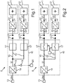
- Fig. 1 shows a stationary charging device 10, to which motor vehicles 11 can be supplied with electrical energy or charging power for charging or recharging a respective electrical energy storage device 12 of the respective motor vehicle 11.
- An energy store 12 can be realized, for example, on the basis of a battery or an electric accumulator, in particular a high-voltage battery.
- the charging device 10 and the motor vehicles 11 together constitute a system S, since the charging device 10 and the motor vehicles 11 are configured and can be operated in a coordinated manner.
- the charging device 10 may be installed, for example, in a parking garage or in a parking lot.
- the charging device 10 provides a charging infrastructure, by means of which an alternating voltage Uac from an electrical supply network 13 can be converted by means of a central converter device 14 into a DC voltage U, which can then be distributed by means of an electrical distribution device 15 of the charging device 10 to a plurality of locally spaced charging interfaces 16 , At the charging interfaces 16 so the DC voltage U is provided. It can e.g. several parking spaces for the motor vehicles 11 may be provided and at each of the parking spaces, one of the charging interfaces 16 may be arranged.
- the DC voltage U may be of the amount here in particular less than 60 volts or 60 volts.
- the DC voltage U can also be greater than 60V. It can then be provided HV-safe connector (HV - high voltage).
- the distribution device 15 can be realized or formed, for example, on the basis of a busbar arrangement and / or cable arrangement with at least one busbar and / or at least one cable 15 '.
- the at least one busbar and / or the at least one cable 15 ' can be permanently or temporarily installed here.
- a blocking device 17 can be provided for each or some or one of the charging interfaces 16.
- Fig. 1 is as a blocking device exemplified a backup provided as a protective measure.
- a waste heat 19 produced in the converter device 14 during operation can be dissipated by means of a heat exchanger device 18 and, for example, dissipated or transferred into a heating circuit 20 of a heating device, for example of a building.
- Each of the motor vehicles 11 is independently capable of generating a charging voltage U1, U2 for its respective energy store 12 from the DC voltage U provided at the respective charging interface 16 in order to recharge it.
- a motor vehicle 11 can pick up the DC voltage U provided there by means of a tapping device 21 at one of the charging interfaces 16 and convert it into the respective charging voltage U1, U2 by means of its own DC-DC converter 22.
- At least one of the charging voltages U1, U2 can be different from the DC voltage.
- a current intensity of a charging current I1, I2 and / or a transmitted charging power is set.
- the amount of the charging voltage U1, U2 can be adjusted by a respective control device 23 of the motor vehicle 11, so that indirectly by the charging current I1, I2 and / or the charging power is set.
- the control device 23 can be realized on the basis of a control device and / or an electronic circuit.
- Fig. 2 illustrates a variant of the charging system S, in which the blocking means 17 of the charging interfaces 16 can be designed switchable, so for example, may have a switching device in the form of, for example, a respective contactor or multiple shooters.
- a control center 24 of the charging device 10 can switch each blocking device 17 according to electrically blocking or electrically conductive, regardless of the other blocking devices.
- the control center 24 may be based on, for example, a central computer and / or an electronic circuit.
- the blocking device 17 may, in addition to the switching device, also include a protective device as described in connection with FIG Fig. 1 has been described.
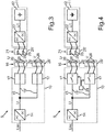
- Fig. 3 illustrates how the charging interfaces 16 and correspondingly the tapping device 21 can be designed bipolar, thereby tapping the DC voltage U between the two poles can.
- the tapping device 21 may for this purpose have electrical contact units 25, which may comprise, for example, copper and / or aluminum.
- the contact units 25 together form a contact pair 25 '.
- each charging interface 16 each have a mating contact unit 26, which together constitute a mating contact pair 26'.
- the mating contact units 26 may be realized on the basis of copper and / or aluminum.
- the contact pair 25 ' may be designed to be movable relative to a remainder of the motor vehicle 11.
- the mating contact pair 26 ' may be designed to be movable relative to a remainder of the charging device 10.
- Fig. 4 1 illustrates an embodiment with the said contact units 25 and mating contact units 26 and the switchable blocking devices 17 with control center 24.
- Fig. 5 illustrates how a communication between a control device 23 of a motor vehicle 11 on the one hand and the control center 24 of the charging device 10 on the other hand can be made so that the motor vehicle 11 from a charging interface 16 can be enabled or switched so that the DC voltage U at the charging interface 16 for tapping by the tapping device 21 of a motor vehicle 11 is ready.
- the blocking device 17 is switched from an electrically blocking to an electrically conductive state.
- the communication can be done in the in Fig. 5 illustrated embodiment via the tapping device 21 and the charging interface 16 are wired.
- it may be a respective electrical guide element 27 of the tapping device 21 and the charging interface 16 are used for signal transmission.
- Such a guide element 27 may be a cable or a busbar.
- PLC Power Line Communication
- the control device 23 can signal, for example, that it is authorized and / or ready to pick up the DC voltage U. Accordingly, the control center 24 can then switch the blocking device 17 from the electrically blocking state into the electrically conducting state in this case.
- the DC voltage U is then available at the charging interface 16 and can be generated by the tapping device 21 in the manner described for generating the charging voltage U1 and the charging current I1.
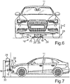
- Fig. 6 illustrates a frontal view of an embodiment of a motor vehicle 11 of the charging system. It is shown how a charging interface 16 for the motor vehicle 11 can be provided below or at the bottom on a parking space 28. It is shown how the tapping device 21 can be designed so that it can move relative to the rest of the motor vehicle 11, in that an actuator device 29 can move the electrical contact units 25 of the contact pair 25 'vertically along a z-direction Z (so-called Z-mover).
- the electrical contact units 25 may in this case be configured in each case as a stamp, for example, which can be extended by means of the actuator 29 down to the bottom of the parking lot 28, where the mating contact units 26 of the mating contact pair 26 'can be located. It can also be provided the other way around (not shown) to move the mating contact units 26 along the z-direction Z towards a vehicle floor of the motor vehicle 11, where the contact units 25 can be located.
- Fig. 7 illustrates how the tapping device 21 can be arranged frontally on a front of the motor vehicle 11.
- the charging interface 16 can in this case, for example, on a wall 30 which defines a parking lot 28, be arranged.
- an actuator device 29 may be provided for the mating contact units 26.
- Fig. 8 illustrates how in a parking lot 28, the mating contact pair 26 'can be arranged with the mating contact units 26 on a ceiling 32 above the parking lot 28.
- the contact units 25 of the contact pair 25 may be provided, for example, on a roof of the motor vehicle 11.
- An actuator device 29 may be configured, for example, to lower the mating contact units 26 to the vehicle 16.
- the actuator 29, for example have the stamp described.
- FIG. 10 illustrates a method that may be performed for charging a motor vehicle 11 or multiple motor vehicles 11 in the charging system S.
- a contact movement M of the contact unit 25 'relative to the mating contact unit 26' can also be provided by means of the actuator device 29 in order to abrade, for example, corrosion residues or thinning on a contact surface between the contact unit 25 'and the mating contact unit 26'. This reduces the contact resistance.
- a DC voltage U can be generated from an AC voltage of a supply network by a central converter device of the charging device.
- the DC voltage U can be distributed by a distribution device 15 to a plurality of charging interfaces 16, without being converted once again.
- the DC voltage U for all motor vehicles 11 can be provided at the charging interfaces 16.
- each of the motor vehicles 11 can then tap the DC voltage U by means of its own tap device 21 and convert the tapped DC voltage U by means of an on-board DC converter 22 and provide the converted DC voltage U1 to the energy storage 12 of the motor vehicle 11, wherein a control device 23 of the motor vehicle 11 controls the DC-DC converter 22 and thereby adjusts the charging current I1, I2 and / or a transmitted charging power.
Landscapes
- Engineering & Computer Science (AREA)
- Power Engineering (AREA)
- Transportation (AREA)
- Mechanical Engineering (AREA)
- Life Sciences & Earth Sciences (AREA)
- Sustainable Development (AREA)
- Sustainable Energy (AREA)
- Charge And Discharge Circuits For Batteries Or The Like (AREA)
- Electric Propulsion And Braking For Vehicles (AREA)
Applications Claiming Priority (1)
| Application Number | Priority Date | Filing Date | Title |
|---|---|---|---|
| DE102018205040.6A DE102018205040B4 (de) | 2018-04-04 | 2018-04-04 | Ladesystem und Verfahren zum Aufladen eines jeweiligen elektrischen Energiespeichers mehrerer Kraftfahrzeuge sowie stationäre Ladevorrichtung und Kraftfahrzeug |
Publications (1)
| Publication Number | Publication Date |
|---|---|
| EP3549812A1 true EP3549812A1 (fr) | 2019-10-09 |
Family
ID=65801970
Family Applications (1)
| Application Number | Title | Priority Date | Filing Date |
|---|---|---|---|
| EP19162475.8A Pending EP3549812A1 (fr) | 2018-04-04 | 2019-03-13 | Système de charge et procédé de charge d'un accumulateur d'énergie électrique respectif d'une pluralité de véhicules automobiles ainsi que dispositif de charge stationnaire et véhicule automobile |
Country Status (2)
| Country | Link |
|---|---|
| EP (1) | EP3549812A1 (fr) |
| DE (1) | DE102018205040B4 (fr) |
Cited By (3)
| Publication number | Priority date | Publication date | Assignee | Title |
|---|---|---|---|---|
| US20210276437A1 (en) * | 2020-03-09 | 2021-09-09 | Audi Ag | Energy supply device for providing electrical energy to a motor vehicle, method for operating an energy supply device, method for manufacturing energy supply devices, and energy supply arrangement |
| CN114336816A (zh) * | 2020-09-29 | 2022-04-12 | 深圳英集芯科技股份有限公司 | 充电方法和相关充电设备及相关充电控制芯片 |
| WO2025080601A1 (fr) * | 2023-10-12 | 2025-04-17 | Bae Systems Controls Inc. | Chargeurs ca embarqués à shuntage des inducteurs dans des véhicules connectés à une source d'alimentation ca |
Citations (4)
| Publication number | Priority date | Publication date | Assignee | Title |
|---|---|---|---|---|
| DE4344563C1 (de) * | 1993-12-24 | 1994-12-08 | Daimler Benz Ag | Batterieladevorrichtung für ein Elektrofahrzeug |
| US20120326668A1 (en) * | 2011-06-27 | 2012-12-27 | Bloom Energy Corporation | Electrical vehicle charging using fuel cell system |
| EP2716490A1 (fr) * | 2011-05-27 | 2014-04-09 | Toyota Jidosha Kabushiki Kaisha | Véhicule |
| DE102015000593A1 (de) * | 2015-01-16 | 2016-07-21 | Audi Ag | Hochspannungsbatterie für ein Kraftfahrzeug und Kraftfahrzeug |
Family Cites Families (8)
| Publication number | Priority date | Publication date | Assignee | Title |
|---|---|---|---|---|
| CH689748A5 (de) | 1995-10-13 | 1999-09-30 | Asmo Engineering | Vorrichtung zum Laden von Batterien von Elektrofahrzeugen. |
| EP2349774A2 (fr) | 2008-11-03 | 2011-08-03 | Andreas Stopp | Procédé de charge automatique de véhicules entièrement ou partiellement électriques et système pour établir un contact de charge |
| NL2004746C2 (en) | 2010-05-19 | 2011-11-22 | Epyon B V | Charging system for electric vehicles. |
| DE102011079430A1 (de) | 2011-07-19 | 2013-01-24 | Siemens Aktiengesellschaft | DC-Ladestation zum Aufladen mehrerer Energiespeichereinrichtungen |
| WO2013180324A1 (fr) | 2012-05-31 | 2013-12-05 | 한국철도기술연구원 | Chargeur électrique polyvalent pour véhicules électriques, adapté aux réseaux de distribution à courant continu, et utilisant un convertisseur continu-continu à grande capacité |
| DE102013200949A1 (de) | 2013-01-22 | 2014-07-24 | Siemens Aktiengesellschaft | Ladeeinrichtung zum Laden einer Anzahl N von Elektrofahrzeugen und Ladestation |
| DE102013204256A1 (de) | 2013-03-12 | 2014-09-18 | Bayerische Motoren Werke Aktiengesellschaft | Ladevorrichtung für ein Elektrofahrzeug |
| US10044209B2 (en) | 2015-12-01 | 2018-08-07 | GM Global Technology Operations LLC | Method and apparatus for charging a high-voltage battery assembly |
-
2018
- 2018-04-04 DE DE102018205040.6A patent/DE102018205040B4/de active Active
-
2019
- 2019-03-13 EP EP19162475.8A patent/EP3549812A1/fr active Pending
Patent Citations (4)
| Publication number | Priority date | Publication date | Assignee | Title |
|---|---|---|---|---|
| DE4344563C1 (de) * | 1993-12-24 | 1994-12-08 | Daimler Benz Ag | Batterieladevorrichtung für ein Elektrofahrzeug |
| EP2716490A1 (fr) * | 2011-05-27 | 2014-04-09 | Toyota Jidosha Kabushiki Kaisha | Véhicule |
| US20120326668A1 (en) * | 2011-06-27 | 2012-12-27 | Bloom Energy Corporation | Electrical vehicle charging using fuel cell system |
| DE102015000593A1 (de) * | 2015-01-16 | 2016-07-21 | Audi Ag | Hochspannungsbatterie für ein Kraftfahrzeug und Kraftfahrzeug |
Cited By (4)
| Publication number | Priority date | Publication date | Assignee | Title |
|---|---|---|---|---|
| US20210276437A1 (en) * | 2020-03-09 | 2021-09-09 | Audi Ag | Energy supply device for providing electrical energy to a motor vehicle, method for operating an energy supply device, method for manufacturing energy supply devices, and energy supply arrangement |
| CN114336816A (zh) * | 2020-09-29 | 2022-04-12 | 深圳英集芯科技股份有限公司 | 充电方法和相关充电设备及相关充电控制芯片 |
| WO2025080601A1 (fr) * | 2023-10-12 | 2025-04-17 | Bae Systems Controls Inc. | Chargeurs ca embarqués à shuntage des inducteurs dans des véhicules connectés à une source d'alimentation ca |
| US12337713B2 (en) | 2023-10-12 | 2025-06-24 | Bae Systems Controls Inc. | Field weakening on-board AC chargers in vehicles connected to an AC power source |
Also Published As
| Publication number | Publication date |
|---|---|
| DE102018205040B4 (de) | 2024-09-19 |
| DE102018205040A1 (de) | 2019-10-10 |
Similar Documents
| Publication | Publication Date | Title |
|---|---|---|
| EP2496436B1 (fr) | Système de charge pour véhicules électriques | |
| EP3521099B1 (fr) | Système de charge doté d'au moins une colonne de charge pour véhicules électriques et procédé de charge d'un ou d'une pluralité de véhicules électriques | |
| EP2699446B1 (fr) | Dispositif de charge pour véhicule | |
| EP2611644B1 (fr) | Système de charge d'une batterie rechargeable d'un véhicule électrique | |
| WO2018166815A1 (fr) | Accumulateur stationnaire servant à l'accumulation temporaire d'énergie électrique dans un réseau d'alimentation électrique ainsi que procédé de fonctionnement et module de rééquipement pour l'accumulateur stationnaire | |
| EP3533660B1 (fr) | Procédé de commande de charge d'une station de charge pour un véhicule électrique | |
| DE102021125345A1 (de) | Kopplungsvorrichtung für ein Elektrofahrzeug | |
| WO2019242928A1 (fr) | Procédé de configuration d'un système de charge et système de charge pour charger l'accumulateur d'énergie électrique d'un véhicule | |
| EP1386389A1 (fr) | Dispositif pour alimenter en energie le reseau de bord multitension d'un vehicule | |
| DE102018112622A1 (de) | Ladeanlage, Ladeverfahren und Ladesystem | |
| DE102011079430A1 (de) | DC-Ladestation zum Aufladen mehrerer Energiespeichereinrichtungen | |
| EP3666585A1 (fr) | Véhicule électrique et système de recharge | |
| DE102018205040B4 (de) | Ladesystem und Verfahren zum Aufladen eines jeweiligen elektrischen Energiespeichers mehrerer Kraftfahrzeuge sowie stationäre Ladevorrichtung und Kraftfahrzeug | |
| DE102011076599A1 (de) | Elektrisches Ladesystem | |
| EP2777129B1 (fr) | Dispositif de charge | |
| DE102018202260A1 (de) | Ladefahrzeug zum Laden eines elektrischen Energiespeichers eines Elektrofahrzeugs | |
| EP2259949B1 (fr) | Système d'accumulation d'énergie pour un véhicule sur rails | |
| EP3587164B1 (fr) | Système avec unité centrale et pluralité des colonnes de charge à courant continu destinées à charger des véhicules électriques | |
| WO2020229073A1 (fr) | Dispositif, procédé et câble pour injecter de l'énergie électrique dans un réseau d'énergie faisant appel à un accumulateur d'énergie mobile | |
| DE102022003108A1 (de) | Transportable Ladestation zum Laden zumindest eines mobilen elektrischen Energiespeichers und Verfahren zum Betrieb einer Ladestation | |
| EP3533658A1 (fr) | Station de chargement et système de chargement pour vehicule électriques | |
| EP3549814B1 (fr) | Procédé d'attribution des informations de connexion et dispositif de charge | |
| WO2012146306A2 (fr) | Procédé pour limiter la puissance électrique | |
| WO2012163421A1 (fr) | Attribution d'une puissance ou d'une intensité de courant à des dispositifs de charge | |
| DE102020125540A1 (de) | Ladeeinrichtung zum Zuführen von elektrischer Energie an angeschlossene Elektrofahrzeuge |
Legal Events
| Date | Code | Title | Description |
|---|---|---|---|
| PUAI | Public reference made under article 153(3) epc to a published international application that has entered the european phase |
Free format text: ORIGINAL CODE: 0009012 |
|
| STAA | Information on the status of an ep patent application or granted ep patent |
Free format text: STATUS: THE APPLICATION HAS BEEN PUBLISHED |
|
| AK | Designated contracting states |
Kind code of ref document: A1 Designated state(s): AL AT BE BG CH CY CZ DE DK EE ES FI FR GB GR HR HU IE IS IT LI LT LU LV MC MK MT NL NO PL PT RO RS SE SI SK SM TR |
|
| AX | Request for extension of the european patent |
Extension state: BA ME |
|
| STAA | Information on the status of an ep patent application or granted ep patent |
Free format text: STATUS: REQUEST FOR EXAMINATION WAS MADE |
|
| 17P | Request for examination filed |
Effective date: 20200409 |
|
| RBV | Designated contracting states (corrected) |
Designated state(s): AL AT BE BG CH CY CZ DE DK EE ES FI FR GB GR HR HU IE IS IT LI LT LU LV MC MK MT NL NO PL PT RO RS SE SI SK SM TR |
|
| STAA | Information on the status of an ep patent application or granted ep patent |
Free format text: STATUS: EXAMINATION IS IN PROGRESS |
|
| 17Q | First examination report despatched |
Effective date: 20210408 |
|
| P01 | Opt-out of the competence of the unified patent court (upc) registered |
Effective date: 20230529 |