EP3550123A1 - Carter de turbine pour turbocompresseur comportant une distribution a/r linéaire et une distribution de zone non linéaire - Google Patents
Carter de turbine pour turbocompresseur comportant une distribution a/r linéaire et une distribution de zone non linéaire Download PDFInfo
- Publication number
- EP3550123A1 EP3550123A1 EP19162668.8A EP19162668A EP3550123A1 EP 3550123 A1 EP3550123 A1 EP 3550123A1 EP 19162668 A EP19162668 A EP 19162668A EP 3550123 A1 EP3550123 A1 EP 3550123A1
- Authority
- EP
- European Patent Office
- Prior art keywords
- flow passage
- distribution
- inlet
- axis
- volute
- Prior art date
- Legal status (The legal status is an assumption and is not a legal conclusion. Google has not performed a legal analysis and makes no representation as to the accuracy of the status listed.)
- Granted
Links
Images





Classifications
-
- F—MECHANICAL ENGINEERING; LIGHTING; HEATING; WEAPONS; BLASTING
- F01—MACHINES OR ENGINES IN GENERAL; ENGINE PLANTS IN GENERAL; STEAM ENGINES
- F01D—NON-POSITIVE DISPLACEMENT MACHINES OR ENGINES, e.g. STEAM TURBINES
- F01D9/00—Stators
- F01D9/02—Nozzles; Nozzle boxes; Stator blades; Guide conduits, e.g. individual nozzles
- F01D9/026—Scrolls for radial machines or engines
-
- F—MECHANICAL ENGINEERING; LIGHTING; HEATING; WEAPONS; BLASTING
- F01—MACHINES OR ENGINES IN GENERAL; ENGINE PLANTS IN GENERAL; STEAM ENGINES
- F01D—NON-POSITIVE DISPLACEMENT MACHINES OR ENGINES, e.g. STEAM TURBINES
- F01D25/00—Component parts, details, or accessories, not provided for in, or of interest apart from, other groups
- F01D25/24—Casings; Casing parts, e.g. diaphragms, casing fastenings
-
- F—MECHANICAL ENGINEERING; LIGHTING; HEATING; WEAPONS; BLASTING
- F02—COMBUSTION ENGINES; HOT-GAS OR COMBUSTION-PRODUCT ENGINE PLANTS
- F02C—GAS-TURBINE PLANTS; AIR INTAKES FOR JET-PROPULSION PLANTS; CONTROLLING FUEL SUPPLY IN AIR-BREATHING JET-PROPULSION PLANTS
- F02C6/00—Plural gas-turbine plants; Combinations of gas-turbine plants with other apparatus; Adaptations of gas-turbine plants for special use
- F02C6/04—Gas-turbine plants providing heated or pressurised working fluid for other apparatus, e.g. without mechanical power output
- F02C6/10—Gas-turbine plants providing heated or pressurised working fluid for other apparatus, e.g. without mechanical power output supplying working fluid to a user, e.g. a chemical process, which returns working fluid to a turbine of the plant
- F02C6/12—Turbochargers, i.e. plants for augmenting mechanical power output of internal-combustion piston engines by increase of charge pressure
-
- F—MECHANICAL ENGINEERING; LIGHTING; HEATING; WEAPONS; BLASTING
- F04—POSITIVE - DISPLACEMENT MACHINES FOR LIQUIDS; PUMPS FOR LIQUIDS OR ELASTIC FLUIDS
- F04D—NON-POSITIVE-DISPLACEMENT PUMPS
- F04D29/00—Details, component parts, or accessories
- F04D29/40—Casings; Connections of working fluid
- F04D29/42—Casings; Connections of working fluid for radial or helico-centrifugal pumps
- F04D29/4206—Casings; Connections of working fluid for radial or helico-centrifugal pumps especially adapted for elastic fluid pumps
- F04D29/4213—Casings; Connections of working fluid for radial or helico-centrifugal pumps especially adapted for elastic fluid pumps suction ports
-
- F—MECHANICAL ENGINEERING; LIGHTING; HEATING; WEAPONS; BLASTING
- F05—INDEXING SCHEMES RELATING TO ENGINES OR PUMPS IN VARIOUS SUBCLASSES OF CLASSES F01-F04
- F05B—INDEXING SCHEME RELATING TO WIND, SPRING, WEIGHT, INERTIA OR LIKE MOTORS, TO MACHINES OR ENGINES FOR LIQUIDS COVERED BY SUBCLASSES F03B, F03D AND F03G
- F05B2220/00—Application
- F05B2220/40—Application in turbochargers
-
- F—MECHANICAL ENGINEERING; LIGHTING; HEATING; WEAPONS; BLASTING
- F05—INDEXING SCHEMES RELATING TO ENGINES OR PUMPS IN VARIOUS SUBCLASSES OF CLASSES F01-F04
- F05B—INDEXING SCHEME RELATING TO WIND, SPRING, WEIGHT, INERTIA OR LIKE MOTORS, TO MACHINES OR ENGINES FOR LIQUIDS COVERED BY SUBCLASSES F03B, F03D AND F03G
- F05B2240/00—Components
- F05B2240/10—Stators
- F05B2240/14—Casings, housings, nacelles, gondels or the like, protecting or supporting assemblies there within
-
- F—MECHANICAL ENGINEERING; LIGHTING; HEATING; WEAPONS; BLASTING
- F05—INDEXING SCHEMES RELATING TO ENGINES OR PUMPS IN VARIOUS SUBCLASSES OF CLASSES F01-F04
- F05B—INDEXING SCHEME RELATING TO WIND, SPRING, WEIGHT, INERTIA OR LIKE MOTORS, TO MACHINES OR ENGINES FOR LIQUIDS COVERED BY SUBCLASSES F03B, F03D AND F03G
- F05B2250/00—Geometry
- F05B2250/50—Inlet or outlet
- F05B2250/501—Inlet
- F05B2250/5011—Inlet augmenting, i.e. with intercepting fluid flow cross sectional area greater than the rest of the machine behind the inlet
-
- F—MECHANICAL ENGINEERING; LIGHTING; HEATING; WEAPONS; BLASTING
- F05—INDEXING SCHEMES RELATING TO ENGINES OR PUMPS IN VARIOUS SUBCLASSES OF CLASSES F01-F04
- F05B—INDEXING SCHEME RELATING TO WIND, SPRING, WEIGHT, INERTIA OR LIKE MOTORS, TO MACHINES OR ENGINES FOR LIQUIDS COVERED BY SUBCLASSES F03B, F03D AND F03G
- F05B2250/00—Geometry
- F05B2250/70—Shape
- F05B2250/71—Shape curved
-
- F—MECHANICAL ENGINEERING; LIGHTING; HEATING; WEAPONS; BLASTING
- F05—INDEXING SCHEMES RELATING TO ENGINES OR PUMPS IN VARIOUS SUBCLASSES OF CLASSES F01-F04
- F05D—INDEXING SCHEME FOR ASPECTS RELATING TO NON-POSITIVE-DISPLACEMENT MACHINES OR ENGINES, GAS-TURBINES OR JET-PROPULSION PLANTS
- F05D2220/00—Application
- F05D2220/40—Application in turbochargers
-
- F—MECHANICAL ENGINEERING; LIGHTING; HEATING; WEAPONS; BLASTING
- F05—INDEXING SCHEMES RELATING TO ENGINES OR PUMPS IN VARIOUS SUBCLASSES OF CLASSES F01-F04
- F05D—INDEXING SCHEME FOR ASPECTS RELATING TO NON-POSITIVE-DISPLACEMENT MACHINES OR ENGINES, GAS-TURBINES OR JET-PROPULSION PLANTS
- F05D2250/00—Geometry
- F05D2250/30—Arrangement of components
- F05D2250/38—Arrangement of components angled, e.g. sweep angle
Definitions
- the present disclosure generally relates to a turbine housing for a turbocharger and, more particularly, relates to a turbine housing for a turbocharger with a linear Area/Radius (A/R) distribution and nonlinear area and radius distributions.
- A/R Area/Radius
- the turbine section of the turbocharger typically includes a turbine wheel and a turbine housing. Exhaust gas flows into the housing and is directed toward the turbine wheel to drive the wheel in rotation and to drive a compressor wheel, which is mounted on the same shaft as the turbine wheel.
- the shape, dimensions, etc. of the turbine housing may affect performance of the turbocharger. More specifically, the shape of the turbine housing may directly affect how the exhaust gas flows, thereby, affecting how the gas impinges on the turbine wheel.
- the turbine housing may direct exhaust gas toward the turbine wheel with high effectiveness at some engine speeds, but performance may be degraded at other engine speeds. Likewise, there may be a pulse flow of exhaust gas that degrades performance of the turbocharger.
- a turbocharger system in one embodiment, includes a turbine wheel configured to rotate about an axis of rotation.
- the turbocharger system also include a turbine housing that houses the turbine wheel.
- the turbine housing defines at least one scroll with a volute flow passage.
- the volute flow passage has an inlet and an end that are spaced apart along a flow axis in a circumferential direction about the axis of rotation.
- the volute flow passage defines a plurality of cross sections arranged in series along the flow axis from the inlet to the end.
- the plurality of cross sections are taken normal to the flow axis.
- the plurality of cross sections have an area (A) and a centroid, and the centroid is spaced at a radial distance (R) from the axis of rotation.
- the volute flow passage has a sidewall angle distribution from the inlet to the end that is at least partly nonlinear.
- the volute flow passage has an A/R-distribution from the inlet to the end that is substantially linear.
- the volute flow passage has an A-distribution from the inlet to the end that is at least partly nonlinear.
- the plurality of cross sections have an area (A) and a centroid.
- the centroid is spaced at a radial distance (R) from the axis of rotation.
- the volute flow passage has a sidewall angle distribution from the inlet to the end that is at least partly nonlinear.
- the volute flow passage has an A/R-distribution from the inlet to the end that is substantially linear.
- the volute flow passage has an A-distribution from the inlet to the end that is at least partly nonlinear.
- a turbocharger in an additional embodiment, includes a turbine wheel configured to rotate about an axis of rotation.
- the turbocharger further includes a turbine housing that houses the turbine wheel.
- the turbine housing defines at least one scroll with a volute flow passage.
- the volute flow passage has an inlet and an end that are spaced apart along a flow axis in a circumferential direction about the axis of rotation.
- the volute flow passage defines a plurality of cross sections arranged in series along the flow axis from the inlet to the end. The plurality of cross sections are taken normal to the flow axis.
- the plurality of cross sections have an area (A) and a centroid.
- the centroid is spaced at a radial distance (R) from the axis of rotation.
- the volute flow passage has a sidewall angle distribution from the inlet to the end that is at least partly nonlinear.
- the volute flow passage has an A/R-distribution from the inlet to the end that is substantially linear.
- the volute flow passage has a negative exponential A-distribution proximate the inlet.
- the volute flow passage has an R-distribution from the inlet to the end and has two inflection points.
- example embodiments disclosed herein include a turbocharger with a turbine housing having at least one scroll structure (i.e., scroll, volute structure, etc.).
- the turbine housing may have a plurality of scroll structures.
- the turbine housing may have two scroll structures that are mirror images of each other (i.e., twin scrolls).
- the scroll structures may be asymmetrical.
- At least one scroll structure may have an internal volute flow passage that extends along a flow axis in a scroll-like fashion about an axis of rotation of a turbine wheel.
- the flow passage may define an inlet and an end, which are spaced apart in a circumferential direction along the flow axis.
- the cross section of the flow passage (taken perpendicular to the flow axis) may change as the flow passage progressively extends along the flow axis.
- the area (A) of the cross section of the flow passage may gradually reduce as the flow passage progressively extends along the flow axis.
- Another variable that changes along the flow axis is the radial distance (R) from the axis of rotation of the turbine wheel to the centroid of the cross section.
- the turbine housing and/or the flow passage defined therein may be configured according to a linear Area/Radius (A/R) distribution from the inlet to the end.
- A/R Area/Radius
- This feature may provide certain aerodynamic benefits.
- the configuration of the flow passage may provide substantially uniform flow toward the turbine wheel within the turbine housing, from the inlet to the end of the flow passage.
- the linear A/R-distribution may ensure that fluid flowing into the turbine housing impinges on the turbine wheel uniformly over the entire circumference of the turbine wheel.
- the flow angle or inlet angle of the air on the turbine wheel may be highly controlled for increased operating efficiency of the turbocharger.
- the flow passage may be configured according to a non-linear Area (A) distribution from the inlet to the end.
- the flow passage may have a sidewall angle distribution that is at least partly nonlinear from the inlet to the end.
- FIG. 1 is a schematic view of an example turbocharger system 100 that includes a turbocharger 112.
- the turbocharger 112 generally includes a turbocharger housing 101 and a rotor 102.
- the rotor 102 is configured to rotate within the turbocharger housing 101 about an axis of rotor rotation 103.
- the rotor 102 may be supported for rotation about the axis 103 via one or more bearings (not shown).
- the rotor 102 may be rotationally supported by thrust bearings and a plurality of journal bearings. Alternatively, other bearings may be included.
- the turbocharger housing 101 may include a turbine housing 105, a compressor housing 107, and a bearing housing 109.
- the bearing housing 109 may be disposed between the turbine and compressor housings 105, 107.
- the bearing housing 109 may contain the bearings of the rotor 102.
- the rotor 102 includes a turbine wheel 111, a compressor wheel 113, and a shaft 115.
- the turbine wheel 111 is located substantially within the turbine housing 105.
- the compressor wheel 113 is located substantially within the compressor housing 107.
- the shaft 115 extends along the axis of rotation 103, through the bearing housing 109, to connect the turbine wheel 111 to the compressor wheel 113. Accordingly, the turbine wheel 111 and the compressor wheel 113 rotate together about the axis 103.
- the turbine wheel 111 (and thus the rotor 102) is driven in rotation around the axis 103 by the high-pressure and high-temperature exhaust gas stream 121, which becomes a lower-pressure and lower-temperature exhaust gas stream 127 that is released into a downstream exhaust pipe 126.
- the compressor housing 107 and compressor wheel 113 form a compressor (i.e., compressor section, compressor stage).
- the compressor wheel 113 being driven in rotation by the exhaust-gas driven turbine wheel 111, is configured to compress received input air 131 (e.g., ambient air, or already-pressurized air from a previous-stage in a multi-stage compressor) into a pressurized air stream 133.
- the pressurized air stream 133 is ejected circumferentially from the compressor housing 107.
- the compressor housing 107 may have a shape (e.g., a volute shape or otherwise) configured to direct and pressurize the air blown from the compressor wheel 113. Due to the compression process, the pressurized air stream 133 is characterized by an increased temperature, over that of the input air 131.
- the turbine housing 105 may also include an inlet segment 209 that extends in a tangential direction from the first scroll 200 and the second scroll 202.
- the inlet segment 209 may be fluidly connected to the exhaust pipe 120 so as to receive the exhaust gas stream 121 from the engine 125 ( FIG. 1 ). Accordingly, the exhaust gas stream 121 may be directed toward the first volute flow passage 201 and/or the second volute flow passage 203.
- the downstream exhaust pipe 126 ( FIG. 1 ) may also be connected to the turbine housing 105 and may extend along the axis 103 therefrom.
- the exhaust gas stream 121 from the engine 125 may flow along the exhaust pipe 120 and may flow into the inlet segment 209 of the turbine housing 105. This flow may be directed into the first and/or second volute flow passages 201, 203.
- the exhaust may flow in the circumferential direction about the axis 103 and radially inward toward the axis 103 and may flow through the inner diameter opening 206 to impinge upon and drive the turbine wheel 111 in rotation.
- the gas may flow further downstream along the axis 103 into the exhaust pipe 126.
- FIG. 3 illustrates additional features of the first scroll 200 and the first volute flow passage 201 therein.
- a flow axis 269 of the flow passage 201 is indicated as well.
- the first scroll 200 and the first volute flow passage 201 may be representative of the second scroll 202 and the second volute flow passage 203, respectively.
- the first scroll 200 may also define a first sidewall 281 and a second sidewall 283, which both extend between the inner rim 204 to the outer peripheral wall 292.
- the first sidewall 281 may be disposed along the axis 103 between the plane 280 and the second sidewall 283.
- Outer portions of the first and second sidewalls 281, 283 may be disposed at an angle 298 relative to each other (i.e., a sidewall angle).
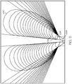
- the flow passage 201 may have a cross section taken perpendicular to the flow axis 269 as represented in FIGS. 4 and 5 .
- the cross section may be defined by the inside surfaces of the first sidewall 281, the second sidewall 283, the outer peripheral wall 292 , and the inner rim 204.
- the cross section may have any suitable shape.
- the cross section may be elongated in the radial direction and may bulge at the outer radial portions.
- the cross section may be more slender closer toward the axis 103.
- the first cross section 290 may represent the flow passage 201 at the inlet 210 (e.g., at the zero-degree (0°) position).
- the second cross section 297 may represent the flow passage 201 at the one-hundred-eighty-degree (180°) position.
- FIG. 5 superimposes multiple cross sections of the flow passage 201 onto a common plane.
- the radial distance (R) from the axis of rotation 103 to the center of the cross section may reduce gradually as the flow passage 201 advances downstream along the flow axis 169.
- the first cross section 290 may define a first centroid 291
- the second cross section 297 may define a second centroid 293.
- the first centroid 291 may be spaced a first radial distance 222 from the axis of rotation 103.
- the second centroid 293 may be spaced a second radial distance 226 from the axis of rotation 103.
- the sidewall angle may change as the flow passage 201 advances downstream along the flow axis 169.
- the sidewall angle 298 at the first cross section 290 (at the inlet 210) may be smaller than the sidewall angle 299 at a third cross section 294 (at the end 212).
- the sidewall angle may gradually increase along the flow axis 169 from the inlet 210 to the end 212.
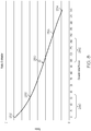
- FIG. 6 represents an example A/R-distribution of the flow passage 201.
- the X-axis represents circumferential position
- the Y-axis represents the ratio of cross sectional area (A) to radial distance (R) of the centroid to the axis 103.
- the graph has been normalized such that the Y-axis ranges from zero (0) to a value of X.
- the line 230 represents the A/R relationship of the flow passage 201, with point 232 representing the ratio at the inlet 210, and point 234 representing the ratio at the end 212.
- the A/R-distribution of the flow passage 201 may be substantially linear from the inlet 210 to the end 212.
- the substantially linear A/R-distribution may provide certain aerodynamic benefits.
- this configuration of the flow passage 201 may provide substantially uniform flow toward the turbine wheel 111, from the inlet 210 to the end 212.
- the linear A/R-distribution may ensure that fluid flowing into the turbine housing impinges on the turbine wheel 111 uniformly over its entire circumference.
- the A-distribution of the flow passage 201 from the inlet 210 to the end 212 may be nonlinear.
- the X-axis represents circumferential position
- the Y-axis represents the area of the cross section in those circumferential positions.
- the graph has been normalized such that the Y-axis ranges from zero (0) to the value of Y.
- the line 240 represents the A-distribution of the flow passage 201, with point 242 representing the area of the cross section at the inlet 210, and the point 244 representing the area of the cross section at the end 212.
- the A-distribution of the flow passage 201 may be configured with a first region 246 that has a negative exponential distribution and a second region 248 that is substantially linear.
- the first region 246 may be proximate the inlet 210 (e.g., from the zero-degree circumferential position to the ninety-degree circumferential position) and may be spaced apart from the end 212 along the flow axis 269.
- the second region 248 may extend from the first region 246 to the end 212.
- the line 240 representing the A-distribution may be concave in the first region 246.
- the R-distribution of the flow passage 201 from the inlet 210 to the end 212 may be nonlinear.
- the X-axis represents circumferential position
- the Y-axis represents the radial distance of the centroid of the cross section to the axis 103.
- the graph has been normalized such that the Y-axis ranges from zero (0) to the value of Z.
- the line 250 represents the R-distribution of the flow passage 201, with point 252 representing the radial distance at the inlet 210, and the point 254 representing the radial distance of the cross section proximate the end 212.
- the R-distribution of the flow passage 201 may have a plurality (e.g., two) inflection points, where the curve changes direction.
- the R-distribution may include a first inflection point 256 and a second inflection point 258.
- the R-distribution may have a first region 260 with a negative exponential distribution proximate the inlet 210 (e.g., from the zero degree (0°) circumferential position to the seventy-degree (70°) circumferential position).
- the R-distribution may also have a second region 262 further downstream with a positive exponential distribution.
- the second region 262 may be defined proximate the end 212 (e.g., from the one-hundred-eighty-degree (180°) circumferential position to the two-hundred-seventy-degree (270°) position) of the flow passage 201.
- the sidewall angle distribution of the flow passage 201 from the inlet 210 to the end 212 may be at least partly nonlinear.
- the X-axis represents circumferential position
- the Y-axis represents the sidewall angle measured between the sidewalls 281, 283.
- the graph has been normalized such that the Y-axis ranges from zero (0) to the value of N.
- the line 295 represents the sidewall angle distribution of the flow passage 201 with point 285 representing the sidewall angle at the inlet 210, and the point 286 representing the sidewall angle proximate the end 212.
- the sidewall angle distribution may have a first region 287 with a positive exponential distribution proximate the inlet 210 (e.g., from the zero degree (0°) circumferential position to the one-hundred-degree (100°) circumferential position).
- the sidewall angle distribution may also have a second region 288 that increases substantially linearly (e.g., from the one-hundred-degree (100°) circumferential position to the three-hundred-sixty-degree (360°) position) of the flow passage 201.
- the A-distribution, the R-distribution, and/or the sidewall angle distribution of the flow passage 201, as described above, may improve performance of the turbocharger 112. For example, these features may ameliorate otherwise negative effects of pulse flow of exhaust gas on operation of the turbocharger 112.
Landscapes
- Engineering & Computer Science (AREA)
- Mechanical Engineering (AREA)
- General Engineering & Computer Science (AREA)
- Chemical & Material Sciences (AREA)
- Chemical Kinetics & Catalysis (AREA)
- General Chemical & Material Sciences (AREA)
- Combustion & Propulsion (AREA)
- Supercharger (AREA)
Applications Claiming Priority (1)
| Application Number | Priority Date | Filing Date | Title |
|---|---|---|---|
| US15/943,408 US10513936B2 (en) | 2018-04-02 | 2018-04-02 | Turbine housing for turbocharger with linear A/R distribution and nonlinear area distribution |
Publications (2)
| Publication Number | Publication Date |
|---|---|
| EP3550123A1 true EP3550123A1 (fr) | 2019-10-09 |
| EP3550123B1 EP3550123B1 (fr) | 2020-09-23 |
Family
ID=65812103
Family Applications (1)
| Application Number | Title | Priority Date | Filing Date |
|---|---|---|---|
| EP19162668.8A Active EP3550123B1 (fr) | 2018-04-02 | 2019-03-13 | Carter de turbine pour turbocompresseur comportant une distribution a/r linéaire et une distribution de zone non linéaire |
Country Status (3)
| Country | Link |
|---|---|
| US (1) | US10513936B2 (fr) |
| EP (1) | EP3550123B1 (fr) |
| CN (1) | CN110344897B (fr) |
Families Citing this family (1)
| Publication number | Priority date | Publication date | Assignee | Title |
|---|---|---|---|---|
| US11976572B2 (en) | 2021-08-23 | 2024-05-07 | Borgwarner Inc. | Method of reducing turbine wheel high cycle fatigue in sector-divided dual volute turbochargers |
Citations (4)
| Publication number | Priority date | Publication date | Assignee | Title |
|---|---|---|---|---|
| EP1304445A2 (fr) * | 2001-10-19 | 2003-04-23 | Mitsubishi Heavy Industries, Ltd. | Configuration de volute et des aubes pour turbines radiales |
| WO2008009936A1 (fr) * | 2006-07-20 | 2008-01-24 | Cummins Turbo Technologies Limited | Carter de turbine pour un turbocompresseur |
| WO2015092373A1 (fr) * | 2013-12-16 | 2015-06-25 | Cummins Ltd | Carter de turbine |
| WO2017176186A1 (fr) * | 2016-04-08 | 2017-10-12 | Scania Cv Ab | Agencement de turbine comprenant une volute avec une section d'écoulement décroissante en continu ayant une valeur réduite successivement |
Family Cites Families (15)
| Publication number | Priority date | Publication date | Assignee | Title |
|---|---|---|---|---|
| IN152940B (fr) * | 1978-10-20 | 1984-05-05 | Cummins Engine Co Inc | |
| US4294073A (en) * | 1979-10-05 | 1981-10-13 | Cummins Engine Company, Inc. | Integral turbine housing and exhaust collector section |
| US4512714A (en) * | 1982-02-16 | 1985-04-23 | Deere & Company | Variable flow turbine |
| JPH05901U (ja) * | 1991-06-19 | 1993-01-08 | 三菱重工業株式会社 | ラジアルタービンのケーシング |
| EP1270924A3 (fr) * | 2001-06-28 | 2004-01-07 | Delphi Technologies, Inc. | Ensemble intégré de collecteur d'admission pour un moteur à combustion interne |
| US7428814B2 (en) * | 2006-03-08 | 2008-09-30 | Melvin Hess Pedersen | Turbine assemblies and related systems for use with turbochargers |
| DE112010003291T5 (de) * | 2009-04-20 | 2013-06-20 | Borgwarner Inc. | Vereinfachter Turbolader mit veränderlicher Geometrie und veränderlichen Diffusordurchflussvolumina |
| US8281771B2 (en) * | 2010-02-16 | 2012-10-09 | Kamtec Inc. | Exhaust gas recirculation valve in vehicle |
| US8834104B2 (en) * | 2010-06-25 | 2014-09-16 | Honeywell International Inc. | Vanes for directing exhaust to a turbine wheel |
| US9091232B2 (en) * | 2010-09-02 | 2015-07-28 | Borgwarner Inc. | Compressor recirculation into annular volume |
| WO2014063714A1 (fr) * | 2012-10-23 | 2014-05-01 | P{����^P{����^P{����^P{����^P{����^@P{����^P{����^P{����^P{����^@P{����^P{����^P{����^P{����^P{����^P{����^@P{����^P{����^P{����^P{����^ | Turbines hydrauliques avec directions d'entrée et de sortie opposées |
| US20140241866A1 (en) * | 2013-02-25 | 2014-08-28 | Honeywell International Inc. | Turbocharger wheel with sound control |
| JP5870083B2 (ja) * | 2013-12-27 | 2016-02-24 | 三菱重工業株式会社 | タービン |
| US10760437B2 (en) * | 2016-09-30 | 2020-09-01 | Garrett Transportation I Inc. | Turbocharger with ported turbine shroud |
| US10900415B2 (en) * | 2017-05-09 | 2021-01-26 | Garrett Transportation I Inc. | Turbocharger having a meridionally divided turbine housing and a variable turbine nozzle |
-
2018
- 2018-04-02 US US15/943,408 patent/US10513936B2/en active Active
-
2019
- 2019-03-13 EP EP19162668.8A patent/EP3550123B1/fr active Active
- 2019-04-02 CN CN201910261952.1A patent/CN110344897B/zh active Active
Patent Citations (4)
| Publication number | Priority date | Publication date | Assignee | Title |
|---|---|---|---|---|
| EP1304445A2 (fr) * | 2001-10-19 | 2003-04-23 | Mitsubishi Heavy Industries, Ltd. | Configuration de volute et des aubes pour turbines radiales |
| WO2008009936A1 (fr) * | 2006-07-20 | 2008-01-24 | Cummins Turbo Technologies Limited | Carter de turbine pour un turbocompresseur |
| WO2015092373A1 (fr) * | 2013-12-16 | 2015-06-25 | Cummins Ltd | Carter de turbine |
| WO2017176186A1 (fr) * | 2016-04-08 | 2017-10-12 | Scania Cv Ab | Agencement de turbine comprenant une volute avec une section d'écoulement décroissante en continu ayant une valeur réduite successivement |
Also Published As
| Publication number | Publication date |
|---|---|
| US10513936B2 (en) | 2019-12-24 |
| EP3550123B1 (fr) | 2020-09-23 |
| CN110344897B (zh) | 2024-11-29 |
| CN110344897A (zh) | 2019-10-18 |
| US20190301294A1 (en) | 2019-10-03 |
Similar Documents
| Publication | Publication Date | Title |
|---|---|---|
| US9951793B2 (en) | Ported shroud geometry to reduce blade-pass noise | |
| US10006290B2 (en) | Functionally asymmetric two-sided turbocharger wheel and diffuser | |
| JP4317327B2 (ja) | 低速度高圧縮比ターボチャージャ | |
| CN102220883B (zh) | 轴流式涡轮机叶轮 | |
| US8453448B2 (en) | Axial turbine | |
| US8453445B2 (en) | Axial turbine with parallel flow compressor | |
| US20070204615A1 (en) | Two-shaft turbocharger | |
| US8353161B2 (en) | High diffusion turbine wheel with hub bulb | |
| US20080229742A1 (en) | Extended Leading-Edge Compressor Wheel | |
| US9988907B2 (en) | Blade features for turbocharger wheel | |
| US9988909B2 (en) | Hub features for turbocharger wheel | |
| US20150159660A1 (en) | Axial turbine with radial vnt vanes | |
| EP2843235B1 (fr) | Roue de turbocompresseur à deux faces structurellement asymétriques | |
| CN104564166A (zh) | 具有弯曲的前边缘的轴向涡轮机叶轮 | |
| US20140165559A1 (en) | Multiple scroll axial turbine | |
| US8850813B2 (en) | Bearing housing shroud | |
| US10443387B2 (en) | Turbine wheel with reduced inertia | |
| EP3550123B1 (fr) | Carter de turbine pour turbocompresseur comportant une distribution a/r linéaire et une distribution de zone non linéaire | |
| EP2292908B1 (fr) | Turbocompresseur dotée d'une discontinuité axiale | |
| US20190257321A1 (en) | Turbocharger with thermo-decoupled wheel contour inlet for water-cooled compressor housing | |
| JP7372988B2 (ja) | タービンハウジング、及びターボチャージャ | |
| FI4031752T3 (fi) | Hukkaportin massavirran johtaminen samankeskisesti virtausoptimoituun aksiaalidiffuusoriin |
Legal Events
| Date | Code | Title | Description |
|---|---|---|---|
| PUAI | Public reference made under article 153(3) epc to a published international application that has entered the european phase |
Free format text: ORIGINAL CODE: 0009012 |
|
| STAA | Information on the status of an ep patent application or granted ep patent |
Free format text: STATUS: REQUEST FOR EXAMINATION WAS MADE |
|
| 17P | Request for examination filed |
Effective date: 20190313 |
|
| AK | Designated contracting states |
Kind code of ref document: A1 Designated state(s): AL AT BE BG CH CY CZ DE DK EE ES FI FR GB GR HR HU IE IS IT LI LT LU LV MC MK MT NL NO PL PT RO RS SE SI SK SM TR |
|
| AX | Request for extension of the european patent |
Extension state: BA ME |
|
| GRAP | Despatch of communication of intention to grant a patent |
Free format text: ORIGINAL CODE: EPIDOSNIGR1 |
|
| STAA | Information on the status of an ep patent application or granted ep patent |
Free format text: STATUS: GRANT OF PATENT IS INTENDED |
|
| INTG | Intention to grant announced |
Effective date: 20200508 |
|
| GRAS | Grant fee paid |
Free format text: ORIGINAL CODE: EPIDOSNIGR3 |
|
| GRAA | (expected) grant |
Free format text: ORIGINAL CODE: 0009210 |
|
| STAA | Information on the status of an ep patent application or granted ep patent |
Free format text: STATUS: THE PATENT HAS BEEN GRANTED |
|
| AK | Designated contracting states |
Kind code of ref document: B1 Designated state(s): AL AT BE BG CH CY CZ DE DK EE ES FI FR GB GR HR HU IE IS IT LI LT LU LV MC MK MT NL NO PL PT RO RS SE SI SK SM TR |
|
| REG | Reference to a national code |
Ref country code: GB Ref legal event code: FG4D |
|
| REG | Reference to a national code |
Ref country code: CH Ref legal event code: EP |
|
| REG | Reference to a national code |
Ref country code: IE Ref legal event code: FG4D |
|
| REG | Reference to a national code |
Ref country code: DE Ref legal event code: R096 Ref document number: 602019000736 Country of ref document: DE Ref country code: AT Ref legal event code: REF Ref document number: 1316590 Country of ref document: AT Kind code of ref document: T Effective date: 20201015 |
|
| PG25 | Lapsed in a contracting state [announced via postgrant information from national office to epo] |
Ref country code: GR Free format text: LAPSE BECAUSE OF FAILURE TO SUBMIT A TRANSLATION OF THE DESCRIPTION OR TO PAY THE FEE WITHIN THE PRESCRIBED TIME-LIMIT Effective date: 20201224 Ref country code: NO Free format text: LAPSE BECAUSE OF FAILURE TO SUBMIT A TRANSLATION OF THE DESCRIPTION OR TO PAY THE FEE WITHIN THE PRESCRIBED TIME-LIMIT Effective date: 20201223 Ref country code: HR Free format text: LAPSE BECAUSE OF FAILURE TO SUBMIT A TRANSLATION OF THE DESCRIPTION OR TO PAY THE FEE WITHIN THE PRESCRIBED TIME-LIMIT Effective date: 20200923 Ref country code: SE Free format text: LAPSE BECAUSE OF FAILURE TO SUBMIT A TRANSLATION OF THE DESCRIPTION OR TO PAY THE FEE WITHIN THE PRESCRIBED TIME-LIMIT Effective date: 20200923 Ref country code: FI Free format text: LAPSE BECAUSE OF FAILURE TO SUBMIT A TRANSLATION OF THE DESCRIPTION OR TO PAY THE FEE WITHIN THE PRESCRIBED TIME-LIMIT Effective date: 20200923 Ref country code: BG Free format text: LAPSE BECAUSE OF FAILURE TO SUBMIT A TRANSLATION OF THE DESCRIPTION OR TO PAY THE FEE WITHIN THE PRESCRIBED TIME-LIMIT Effective date: 20201223 |
|
| REG | Reference to a national code |
Ref country code: AT Ref legal event code: MK05 Ref document number: 1316590 Country of ref document: AT Kind code of ref document: T Effective date: 20200923 |
|
| PG25 | Lapsed in a contracting state [announced via postgrant information from national office to epo] |
Ref country code: LV Free format text: LAPSE BECAUSE OF FAILURE TO SUBMIT A TRANSLATION OF THE DESCRIPTION OR TO PAY THE FEE WITHIN THE PRESCRIBED TIME-LIMIT Effective date: 20200923 Ref country code: RS Free format text: LAPSE BECAUSE OF FAILURE TO SUBMIT A TRANSLATION OF THE DESCRIPTION OR TO PAY THE FEE WITHIN THE PRESCRIBED TIME-LIMIT Effective date: 20200923 |
|
| REG | Reference to a national code |
Ref country code: NL Ref legal event code: MP Effective date: 20200923 |
|
| REG | Reference to a national code |
Ref country code: LT Ref legal event code: MG4D |
|
| PG25 | Lapsed in a contracting state [announced via postgrant information from national office to epo] |
Ref country code: LT Free format text: LAPSE BECAUSE OF FAILURE TO SUBMIT A TRANSLATION OF THE DESCRIPTION OR TO PAY THE FEE WITHIN THE PRESCRIBED TIME-LIMIT Effective date: 20200923 Ref country code: SM Free format text: LAPSE BECAUSE OF FAILURE TO SUBMIT A TRANSLATION OF THE DESCRIPTION OR TO PAY THE FEE WITHIN THE PRESCRIBED TIME-LIMIT Effective date: 20200923 Ref country code: EE Free format text: LAPSE BECAUSE OF FAILURE TO SUBMIT A TRANSLATION OF THE DESCRIPTION OR TO PAY THE FEE WITHIN THE PRESCRIBED TIME-LIMIT Effective date: 20200923 Ref country code: RO Free format text: LAPSE BECAUSE OF FAILURE TO SUBMIT A TRANSLATION OF THE DESCRIPTION OR TO PAY THE FEE WITHIN THE PRESCRIBED TIME-LIMIT Effective date: 20200923 Ref country code: PT Free format text: LAPSE BECAUSE OF FAILURE TO SUBMIT A TRANSLATION OF THE DESCRIPTION OR TO PAY THE FEE WITHIN THE PRESCRIBED TIME-LIMIT Effective date: 20210125 Ref country code: CZ Free format text: LAPSE BECAUSE OF FAILURE TO SUBMIT A TRANSLATION OF THE DESCRIPTION OR TO PAY THE FEE WITHIN THE PRESCRIBED TIME-LIMIT Effective date: 20200923 |
|
| PG25 | Lapsed in a contracting state [announced via postgrant information from national office to epo] |
Ref country code: AL Free format text: LAPSE BECAUSE OF FAILURE TO SUBMIT A TRANSLATION OF THE DESCRIPTION OR TO PAY THE FEE WITHIN THE PRESCRIBED TIME-LIMIT Effective date: 20200923 Ref country code: AT Free format text: LAPSE BECAUSE OF FAILURE TO SUBMIT A TRANSLATION OF THE DESCRIPTION OR TO PAY THE FEE WITHIN THE PRESCRIBED TIME-LIMIT Effective date: 20200923 Ref country code: ES Free format text: LAPSE BECAUSE OF FAILURE TO SUBMIT A TRANSLATION OF THE DESCRIPTION OR TO PAY THE FEE WITHIN THE PRESCRIBED TIME-LIMIT Effective date: 20200923 Ref country code: PL Free format text: LAPSE BECAUSE OF FAILURE TO SUBMIT A TRANSLATION OF THE DESCRIPTION OR TO PAY THE FEE WITHIN THE PRESCRIBED TIME-LIMIT Effective date: 20200923 Ref country code: IS Free format text: LAPSE BECAUSE OF FAILURE TO SUBMIT A TRANSLATION OF THE DESCRIPTION OR TO PAY THE FEE WITHIN THE PRESCRIBED TIME-LIMIT Effective date: 20210123 |
|
| REG | Reference to a national code |
Ref country code: DE Ref legal event code: R097 Ref document number: 602019000736 Country of ref document: DE |
|
| PG25 | Lapsed in a contracting state [announced via postgrant information from national office to epo] |
Ref country code: SK Free format text: LAPSE BECAUSE OF FAILURE TO SUBMIT A TRANSLATION OF THE DESCRIPTION OR TO PAY THE FEE WITHIN THE PRESCRIBED TIME-LIMIT Effective date: 20200923 |
|
| PLBE | No opposition filed within time limit |
Free format text: ORIGINAL CODE: 0009261 |
|
| STAA | Information on the status of an ep patent application or granted ep patent |
Free format text: STATUS: NO OPPOSITION FILED WITHIN TIME LIMIT |
|
| PG25 | Lapsed in a contracting state [announced via postgrant information from national office to epo] |
Ref country code: SI Free format text: LAPSE BECAUSE OF FAILURE TO SUBMIT A TRANSLATION OF THE DESCRIPTION OR TO PAY THE FEE WITHIN THE PRESCRIBED TIME-LIMIT Effective date: 20200923 Ref country code: DK Free format text: LAPSE BECAUSE OF FAILURE TO SUBMIT A TRANSLATION OF THE DESCRIPTION OR TO PAY THE FEE WITHIN THE PRESCRIBED TIME-LIMIT Effective date: 20200923 |
|
| 26N | No opposition filed |
Effective date: 20210624 |
|
| PG25 | Lapsed in a contracting state [announced via postgrant information from national office to epo] |
Ref country code: MC Free format text: LAPSE BECAUSE OF FAILURE TO SUBMIT A TRANSLATION OF THE DESCRIPTION OR TO PAY THE FEE WITHIN THE PRESCRIBED TIME-LIMIT Effective date: 20200923 Ref country code: IT Free format text: LAPSE BECAUSE OF FAILURE TO SUBMIT A TRANSLATION OF THE DESCRIPTION OR TO PAY THE FEE WITHIN THE PRESCRIBED TIME-LIMIT Effective date: 20200923 |
|
| REG | Reference to a national code |
Ref country code: BE Ref legal event code: MM Effective date: 20210331 |
|
| PG25 | Lapsed in a contracting state [announced via postgrant information from national office to epo] |
Ref country code: LU Free format text: LAPSE BECAUSE OF NON-PAYMENT OF DUE FEES Effective date: 20210313 Ref country code: IE Free format text: LAPSE BECAUSE OF NON-PAYMENT OF DUE FEES Effective date: 20210313 |
|
| PG25 | Lapsed in a contracting state [announced via postgrant information from national office to epo] |
Ref country code: BE Free format text: LAPSE BECAUSE OF NON-PAYMENT OF DUE FEES Effective date: 20210331 |
|
| REG | Reference to a national code |
Ref country code: CH Ref legal event code: PL |
|
| PG25 | Lapsed in a contracting state [announced via postgrant information from national office to epo] |
Ref country code: LI Free format text: LAPSE BECAUSE OF NON-PAYMENT OF DUE FEES Effective date: 20220331 Ref country code: CH Free format text: LAPSE BECAUSE OF NON-PAYMENT OF DUE FEES Effective date: 20220331 |
|
| P01 | Opt-out of the competence of the unified patent court (upc) registered |
Effective date: 20230424 |
|
| PG25 | Lapsed in a contracting state [announced via postgrant information from national office to epo] |
Ref country code: NL Free format text: LAPSE BECAUSE OF NON-PAYMENT OF DUE FEES Effective date: 20200923 Ref country code: CY Free format text: LAPSE BECAUSE OF FAILURE TO SUBMIT A TRANSLATION OF THE DESCRIPTION OR TO PAY THE FEE WITHIN THE PRESCRIBED TIME-LIMIT Effective date: 20200923 |
|
| PG25 | Lapsed in a contracting state [announced via postgrant information from national office to epo] |
Ref country code: HU Free format text: LAPSE BECAUSE OF FAILURE TO SUBMIT A TRANSLATION OF THE DESCRIPTION OR TO PAY THE FEE WITHIN THE PRESCRIBED TIME-LIMIT; INVALID AB INITIO Effective date: 20190313 |
|
| PG25 | Lapsed in a contracting state [announced via postgrant information from national office to epo] |
Ref country code: MK Free format text: LAPSE BECAUSE OF FAILURE TO SUBMIT A TRANSLATION OF THE DESCRIPTION OR TO PAY THE FEE WITHIN THE PRESCRIBED TIME-LIMIT Effective date: 20200923 |
|
| PG25 | Lapsed in a contracting state [announced via postgrant information from national office to epo] |
Ref country code: MT Free format text: LAPSE BECAUSE OF FAILURE TO SUBMIT A TRANSLATION OF THE DESCRIPTION OR TO PAY THE FEE WITHIN THE PRESCRIBED TIME-LIMIT Effective date: 20200923 |
|
| PG25 | Lapsed in a contracting state [announced via postgrant information from national office to epo] |
Ref country code: TR Free format text: LAPSE BECAUSE OF FAILURE TO SUBMIT A TRANSLATION OF THE DESCRIPTION OR TO PAY THE FEE WITHIN THE PRESCRIBED TIME-LIMIT Effective date: 20200923 |
|
| PGFP | Annual fee paid to national office [announced via postgrant information from national office to epo] |
Ref country code: GB Payment date: 20260319 Year of fee payment: 8 |
|
| PGFP | Annual fee paid to national office [announced via postgrant information from national office to epo] |
Ref country code: DE Payment date: 20260320 Year of fee payment: 8 |
|
| PGFP | Annual fee paid to national office [announced via postgrant information from national office to epo] |
Ref country code: FR Payment date: 20260323 Year of fee payment: 8 |