EP3550139A1 - Dispositif de serrage de raccords vissés - Google Patents
Dispositif de serrage de raccords vissés Download PDFInfo
- Publication number
- EP3550139A1 EP3550139A1 EP19163027.6A EP19163027A EP3550139A1 EP 3550139 A1 EP3550139 A1 EP 3550139A1 EP 19163027 A EP19163027 A EP 19163027A EP 3550139 A1 EP3550139 A1 EP 3550139A1
- Authority
- EP
- European Patent Office
- Prior art keywords
- tool
- tool carrier
- screw
- nut
- control unit
- Prior art date
- Legal status (The legal status is an assumption and is not a legal conclusion. Google has not performed a legal analysis and makes no representation as to the accuracy of the status listed.)
- Granted
Links
Images


Classifications
-
- B—PERFORMING OPERATIONS; TRANSPORTING
- B23—MACHINE TOOLS; METAL-WORKING NOT OTHERWISE PROVIDED FOR
- B23P—METAL-WORKING NOT OTHERWISE PROVIDED FOR; COMBINED OPERATIONS; UNIVERSAL MACHINE TOOLS
- B23P19/00—Machines for simply fitting together or separating metal parts or objects, or metal and non-metal parts, whether or not involving some deformation; Tools or devices therefor so far as not provided for in other classes
- B23P19/04—Machines for simply fitting together or separating metal parts or objects, or metal and non-metal parts, whether or not involving some deformation; Tools or devices therefor so far as not provided for in other classes for assembling or disassembling parts
- B23P19/06—Screw or nut setting or loosening machines
- B23P19/067—Bolt tensioners
-
- B—PERFORMING OPERATIONS; TRANSPORTING
- B25—HAND TOOLS; PORTABLE POWER-DRIVEN TOOLS; MANIPULATORS
- B25B—TOOLS OR BENCH DEVICES NOT OTHERWISE PROVIDED FOR, FOR FASTENING, CONNECTING, DISENGAGING, OR HOLDING
- B25B29/00—Accessories
- B25B29/02—Bolt tensioners
-
- F—MECHANICAL ENGINEERING; LIGHTING; HEATING; WEAPONS; BLASTING
- F03—MACHINES OR ENGINES FOR LIQUIDS; WIND, SPRING, OR WEIGHT MOTORS; PRODUCING MECHANICAL POWER OR A REACTIVE PROPULSIVE THRUST, NOT OTHERWISE PROVIDED FOR
- F03D—WIND MOTORS
- F03D13/00—Assembly, mounting or commissioning of wind motors; Arrangements specially adapted for transporting wind motor components
- F03D13/10—Assembly of wind motors; Arrangements for erecting wind motors
-
- F—MECHANICAL ENGINEERING; LIGHTING; HEATING; WEAPONS; BLASTING
- F03—MACHINES OR ENGINES FOR LIQUIDS; WIND, SPRING, OR WEIGHT MOTORS; PRODUCING MECHANICAL POWER OR A REACTIVE PROPULSIVE THRUST, NOT OTHERWISE PROVIDED FOR
- F03D—WIND MOTORS
- F03D13/00—Assembly, mounting or commissioning of wind motors; Arrangements specially adapted for transporting wind motor components
- F03D13/20—Arrangements for mounting or supporting wind motors; Masts or towers for wind motors
-
- E—FIXED CONSTRUCTIONS
- E04—BUILDING
- E04H—BUILDINGS OR LIKE STRUCTURES FOR PARTICULAR PURPOSES; SWIMMING OR SPLASH BATHS OR POOLS; MASTS; FENCING; TENTS OR CANOPIES, IN GENERAL
- E04H12/00—Towers; Masts or poles; Chimney stacks; Water-towers; Methods of erecting such structures
- E04H12/02—Structures made of specified materials
- E04H12/08—Structures made of specified materials of metal
- E04H12/085—Details of flanges for tubular masts
-
- Y—GENERAL TAGGING OF NEW TECHNOLOGICAL DEVELOPMENTS; GENERAL TAGGING OF CROSS-SECTIONAL TECHNOLOGIES SPANNING OVER SEVERAL SECTIONS OF THE IPC; TECHNICAL SUBJECTS COVERED BY FORMER USPC CROSS-REFERENCE ART COLLECTIONS [XRACs] AND DIGESTS
- Y02—TECHNOLOGIES OR APPLICATIONS FOR MITIGATION OR ADAPTATION AGAINST CLIMATE CHANGE
- Y02E—REDUCTION OF GREENHOUSE GAS [GHG] EMISSIONS, RELATED TO ENERGY GENERATION, TRANSMISSION OR DISTRIBUTION
- Y02E10/00—Energy generation through renewable energy sources
- Y02E10/70—Wind energy
- Y02E10/72—Wind turbines with rotation axis in wind direction
-
- Y—GENERAL TAGGING OF NEW TECHNOLOGICAL DEVELOPMENTS; GENERAL TAGGING OF CROSS-SECTIONAL TECHNOLOGIES SPANNING OVER SEVERAL SECTIONS OF THE IPC; TECHNICAL SUBJECTS COVERED BY FORMER USPC CROSS-REFERENCE ART COLLECTIONS [XRACs] AND DIGESTS
- Y02—TECHNOLOGIES OR APPLICATIONS FOR MITIGATION OR ADAPTATION AGAINST CLIMATE CHANGE
- Y02E—REDUCTION OF GREENHOUSE GAS [GHG] EMISSIONS, RELATED TO ENERGY GENERATION, TRANSMISSION OR DISTRIBUTION
- Y02E10/00—Energy generation through renewable energy sources
- Y02E10/70—Wind energy
- Y02E10/728—Onshore wind turbines
Definitions
- a device with these features is known from EP 2 607 685 B1 known. It serves to tighten in a series arranged along a flange threaded connections. Each screw is composed of a threaded member and a nut screwed thereon, wherein the nut is supported against the top of the flange. To tighten the screw and rotate the nut relative to the flange is a arranged on a self-propelled vehicle tool.
- the vehicle In order to position the tool above the respective screw connection to be tightened, the vehicle has a position sensor. Due to the position signals detected by the sensor, the vehicle with the tool arranged thereon is driven in a controlled manner until it is clear from the signals that the tool is in axial alignment with the screw axis of the screw connection to be tightened.
- the position signals of the position sensor are processed by control technology into signals for the drive of the vehicle.
- the controller is also adapted to control the tightening process.
- the positioning of the vehicle under evaluation of the signals of the position sensor is technically complex because of the necessary accuracy.
- the position sensor if this e.g. is designed for sensing upward from the top of the flange of protruding structures, can be irritated by objects that are not part of the screw. Needed is therefore a very good, but also expensive Sensiertechnik.
- the invention is therefore based on the object by technical measures moving the movable by means of a controlled traction drive along the flange connection tool to perform in the next working position technically less expensive and still safe.
- the control unit for starting the respective working position of the tool carrier includes a Weg Kunststoffmodul with a path control, which is adapted to stop after reaching a predetermined path length as the target drive.
- the travel control implemented as a module of the control unit is designed to stop the travel drive as a setpoint or target variable after reaching a travel distance predetermined in the control unit, and thus to interrupt the travel of the tool carrier.
- the respective next working position can be approached reliably even without the evaluation of position signals of a position sensor. Because such a sensor works reliably only when he is able to safely and reliably detect features or structures that are characteristic of the approaching screw. Achieving this error-free, requires a high technical effort in the Sensierelektronik used and in the conversion into driving signals. This type of position determination is also not always error-free, since structures that do not belong to the screw can affect the sensor signal with the risk that the next tightening screw is not found secure.
- the invention makes use of the knowledge that with annular flange connections, as they are typical for the screwing of tower sections of a wind turbine, the positions of the screw connections are determined on the construction side and thus known. Using the design data, it is therefore possible to determine with high accuracy at least the relative arrangement of the screw connections to one another. Because usually have the screw always a constant distance, ie circumferential distance to each other. Once the position of a first tightening screw securely found, the positions can be calculate all other screw due to geometric relationships, and thus in particular to be traversed in the circumferential direction of the flange path lengths, ie distances.
- the control unit comprises a route control module with internal distance or distance specifications, wherein the implemented in the route control module vehicle control method is designed to stop after reaching the distance or distance specification as a target size of the drive, so that reached at the time at this point Working position of the screwing process can be initiated, which also takes place depending on signals from the control unit.
- the invention builds on a control method with path control and taking advantage of the known geometric positions of the screw axes of all screw, is freely programmable in the route control module, in which order the screw are tightened. Because not always it is advantageous to next tighten the adjacent screw each. It may also be advantageous to tighten, after tightening a nut next, for example, the nut of a screw connection opposite the center of the flanged connection, and so on.
- the tool carrier is provided for its support on the upper side of the flange connection with rollers which are mounted on horizontal axes of rotation on the tool carrier.
- the task of these rollers is, above all, to carry the weight of the tool carrier with the tool arranged thereon.
- the tool carrier may be provided for its lateral support, for example against the inner wall of the tower of the wind turbine, with additional rollers which are mounted on substantially vertical axes of rotation on the tool carrier.
- the tool carrier is provided to its lateral guide with rigidly mounted alignment elements on which an extending in the direction of travel alignment surface is formed, the surface normal is opposite to the direction in which the tool carrier supported on the additional roles, so on the supported against the vertical inner wall roles.
- the alignment surfaces are in a plane in which they can be supported on the backs of the exposed threaded end of the screw.
- the alignment elements guide the car sideways and prevent it from leaving its intended driving line laterally. With effect in the opposite direction, ie to the outside, corresponding alignment elements or alignment surfaces are not required. Because the lateral guidance of the car in this direction is already achieved on the additional roles.
- rollers ie those on horizontal axes of rotation and those mounted on substantially vertical axes of rotation, need not all be driven. Rather, an embodiment is preferred in which the rollers are only partly, for example only a single roller, driven rollers. The remaining roles are then non-driven, revolving roles.
- each driven roller is one of those rollers which are mounted on horizontal axes of rotation.
- another embodiment proposes a coupling, preferably an electromagnetic clutch, between the or each driven roller and a drive motor of the travel drive which drives this roller. If the clutch is disconnected or switched off, these wheels of the vehicle are thereby also freely rotatable, so that the vehicle can move freely and with little friction in the direction of travel, and the resulting play makes it easier to center the tool on the screw axis of the respective screw connection.
- a coupling preferably an electromagnetic clutch
- control unit is preferably additionally designed to switch on and / or off the clutch via clutch switching signals.
- At least one of the rollers for the purpose of detecting rotation angle can be rotatably coupled with an angle encoder. This detects the rotation angle of the roller, from which in the control unit the exact distance traveled by the roller can be calculated so as to arrive at exact values in the path control for starting the next screw connection.
- the angle encoder is not arranged on the same axis on which the roller is mounted on the vehicle, the angle encoder should be coupled via a chain or working with a corresponding slip-free timing belt with the fwinkelcod exig role.
- the angle encoder is signal-technically connected to the path control of the control unit.
- the tool carrier forming the vehicle is preferably provided with a vertical guide, via which the tool is adjustably mounted in height on the tool carrier.
- a further embodiment provides a transverse guide with guide direction transversely to the longitudinal extension or direction of travel of the tool carrier.
- the vertical guide and / or the tool is mounted horizontally displaceable on the tool carrier.
- the transverse guide is designed particularly low friction and provided with a spring arrangement which acts on the vertical guide or the tool with a restoring force in a middle position.
- the tool used in the device can, for. As an electrically or hydraulically driven, working with a high torque torque screwing. However, preference is given to a largely torsion-free method of tightening the screw connections. Such tightening is made possible when the tool is a screw-clamping cylinder operating axially with respect to the respective screw connection.
- Such bolt tension cylinders are known. They usually work with hydraulic power, are provided with a hydraulic housing surrounding a cylinder housing and a rotatably mounted in the cylinder housing exchange bushing, which is screwed to a threaded end of the screw. Part of such a screw tensioning cylinder is also a rotary sleeve for positive entrainment, i. Turning the nut while the threaded element of the screw connection is slightly stretched by the hydraulic pressure.
- a screw tensioning cylinder as a tool, this is provided with an electric drive for rotating the exchange socket.
- the screw tensioning cylinder can be provided with a second electric drive. This is responsible for the rotation of the rotary sleeve and thus the application of the mother, and is additionally designed for a vertical adjustment of the screw tensioning cylinder relative to the tool carrier.
- An embodiment of the device is therefore characterized by a leading from a hydraulic pump to the hydraulic working space of the screw tensioning cylinder hydraulic line.
- the hydraulic pump is arranged separately from the bolt tensioning cylinder and the vehicle on which the bolt tensioning cylinder is arranged in a stationary position and is part of an energy module.
- control unit is arranged on the energy module and arranged, for example together with this on a support.
- the control unit For the transmission of the traction drive control signals and the tool control signals leads an electrical signal line from the control unit to the tool carrier, wherein the signal line can be mechanically connected at least to a partial length to the power supply line.
- pivoting frame with one or more vertical pivot axes, wherein the frame is provided for its attachment with fastening means, and a longitudinal portion of the power supply line is mounted in the frame.
- the pivotable frame is adapted to support the power supply line over a rotation angle of approximately 360 °.
- the tool carrier has a feedthrough for the power supply line, wherein the feedthrough is located on a slider which is movably arranged on the tool carrier, preferably in the direction of travel of the tool carrier movable.
- the device for tightening screw is composed of a movable unit 1, a spatially separated stationary unit 2 and a wiring harness, in particular a supply and signal string 3, between the movable unit 1 and the stationary unit 2.
- Part of the movable unit. 1 is a tool 5 for tightening screw.
- the tool is in the embodiment described in more detail here, a hydraulically operated bolt tensioning cylinder 5.
- the stationary unit 2 is the power supply of the device.
- a component of the stationary unit 2 is an electronic control unit 4, which in turn comprises inter alia a travel control module 4A and a documentation module 4B.
- a data record is stored for each individual tightened screw connection, which thus makes it possible to subsequently check the most important characteristics of the screwing process.
- the tool 5 is arranged in height adjustable on a movable carriage 6 by a drive.
- the carriage 6 is therefore the tool carrier of the device.
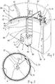
- the carriage or tool carrier is adapted to travel in various circumferential positions along an annular flange connection 7, which is part of a tower-shaped wind power plant, in order to tighten, retighten or release a screw connection there at each of these positions.
- the flange 7 is here a double flange of an upper annular flange 7A and a preferably flat abutting lower annular flange 7B.
- the upper annular flange 7A is located at the bottom of an upper annular tower section 8A.
- the lower annular flange 7B is located at the upper edge of a lower tower section 8B.
- Such wind turbines with heights up to 150 m consist of mounting reasons tower sections. These are essentially cylindrical and enclose a circular space 9 surrounded by the flange connection 7.
- the tower sections can taper conically upwards.
- the tower sections are screwed together by the annular flange 7A is integrally formed on the respective upper tower section 8A of the annular flange 7A, and on the respectively immediately below tower section 8B, the annular flange 7B.
- the thus consisting of two annular flanges flange 7 is held together by a variety of screw. These are arranged at equal intervals distributed over the circumference.
- Each screw 10 consists of a bolt-like threaded member 11 and a screwed onto the threaded portion of the threaded member 11 threaded nut 12.
- the threaded nut 12 is supported with its underside on the preferably flat top of the annular flange 7A.
- the threaded element 11 is formed in the embodiment in such a way that it is supported like a screw with a radially enlarged collar or head from below against the lower annular flange 7 B of the flange connection 7.
- the screw 10 are evenly around the space 9 around, that is distributed at equal intervals along the flange 7.
- the circumferential distance of the screw axis of a screw to the screw axis of the immediately following screw is therefore always the same. Therefore, if the relative to the center of the space 9 radius of the ring on which the axes of the screw 10 are located, is known and also the total number of screw, the distances in the circumferential direction between the axes of the screw can be calculated.
- These geometric specifications are used to move the carriage 6 with the tool 5 arranged thereon along the extension of the flange 7 into individual working positions, wherein each working position is characterized in that the tool 5 is above and in alignment with the axis of each to be attracted Screw 10 is located.
- the tool 5 used in the device may be a hydraulic torque wrench, an electric wrench or a bolt tensioning cylinder.
- the variant of the screw-tensioning cylinder is characterized in particular when tightening screw by the fact that a largely torsion-free bolt tensioning method is achieved, ie without the occurrence of larger torsional forces on the screw length.
- the nut 12 is not directly rotated with high torque, but it is stretched, for example, by hydraulic forces, the threaded member 11 in its longitudinal direction, whereby the bottom of the nut 12 is released from the annular flange 7A. In the so stretched state, the nut 12 is tightened with relatively little torque.
- a bolt tensioning cylinder 5 and such a bolt tensioning method with elongation of the threaded member 11 will be described later.
- All screw 10 extend with their Verschraubungsachsen perpendicular to the top of the annular flange 7A and parallel to the central main axis of the tower sections 8A, 8B.
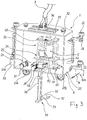
- the basic element of the movable unit 1 is the tool carrier 20.
- the tool carrier 20 In order that it can be moved into individual working positions along the flange connection, the tool carrier 20 is provided with a plurality of rollers, which are partly driven and thus move the tool carrier 20 forward, and which are not driven in part, that is only roll along with the procedure.
- rollers 21A, 21B are present, via which the tool carrier 20 is supported on the upper side of the flange connection 7.
- the rollers 21A, 21B are mounted on horizontal axes of rotation on the tool carrier 20.
- the roller 21A is a driven roller, the roller 21B hung a freely revolving roller.
- the rollers 21A, 21B carry the major part of the weight forces of the tool carrier 20 and the units arranged thereon, including the tool 5. Since the rollers 21A, 21B are heavily weighted, it makes sense that at least one of these rollers, here the roller 21A, the drive roller is.
- An electric drive motor 24 drives the roller 21A and together form the travel drive of the device.
- the drive motor 24 of the traction drive is not seated on the same shaft as the driven roller 21A, but a toothed belt or a chain transmits the rotation of the drive motor 24 in an equal, translated or reduced rotation of the drive roller 21A. However, as long as there is enough space, the drive motor 24 may be disposed on the same shaft as the roller 21A.
- the traction drive motor 24 receives drive control signals from the control unit 4.
- a switchable clutch 25 is arranged, preferably an electromagnetic clutch.
- the clutch 25 receives its clutch switching signals also from the electronic control unit 4. If the clutch 25 is disconnected or turned off, thereby the roller 24A is freely rotatable, so that the tool carrier 20 can move freely in the direction of travel and the possible game centering of the tool 5 to the screw axis of the respective screw 10 simplified.
- rollers 22 are mounted on the tool carrier 20 . These additional rollers support the carriage against the inner wall 23 of the tower section.
- the rollers 22 are compared to the rollers 21A, 21B, only slightly weighted. However, they are supported against the inner wall 23, which is achieved by an arrangement of the rollers 21A, 21B, in which the center of gravity of the carriage is located farther out than the rolling line of the rollers 21A, 21B.
- the additional rollers 22 are not driven, so only idler roles.
- at least one of the rollers 22 is coupled slip-free with an angle encoder 26.
- the angle encoder 26 allows the sensing of angular signals of the roller. From the angle signals of the processor of the electronic control unit 4 calculates the distance of the tool carrier 20 along the inner wall 23. This in turn can be calculated by means of the processor and check which distances the tool carrier 20 along the ring on which the screw 10 are arranged travels or has traveled.
- a preferably twice present alignment element 30 is attached to the bottom of the tool carrier 20.
- the alignment element 30 is provided with an alignment surface 30A extending in the direction of travel, the surface normal of which points inwards and therefore opposite to the direction in which the tool carrier is supported by the additional rollers 22.
- the alignment surfaces 30A are disposed at such a height on the carriage 6 that they are in operation at the level of the threaded end portions 11A of the threaded members 11 and above the nut 12. They are also slightly outward of the threaded end portions 11A, at which they can be supported.
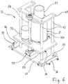
- Components of the driven tool carrier 20 are a lower platform 31 and a fixed upper platform 32 to the lower platform 31. Under the lower platform 31, the rollers 21A, 21B are supported. For easy lifting and transporting the complete carriage 6 eyelets are attached to the upper platform 32, in which a crane hook can be engaged.
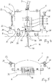
- a frame 33 accommodating the tool 5 is supported on a surface at the top of the lower platform 31, a frame 33 accommodating the tool 5 is supported.
- the frame 33 is formed as a vertical guide 34 for height adjustment of the tool 5.
- transverse guide 35 with guide direction transverse to the longitudinal direction and thus the direction of travel of the tool carrier 20 are present.
- the frame 33 and thus the tool 5 disposed therein is slidably mounted on the platform 31, with displacement possibility transverse to the direction of travel of the tool carrier.
- a spring arrangement 36 which, in the absence of transverse forces, holds the frame 33 in a central position with respect to the platform 31. So act no lateral forces on the tool 5 and thus on the frame 33, this, guided by the transverse guide 35 and under the force of the spring assembly 36, automatically returns to the center position.
- the frame 33 also forms a vertical guide 34 for the height adjustment of the tool 5.
- the frame is composed of the slidably resting on the platform 31 and guided in the transverse guide 35 frame base 41, rigidly fixed to the frame base, vertical guide rods 42, from an upper frame frame 49 connecting the upper ends of these rods and a frame frame 50 adjustable in height by motor drive.
- the frame frame 50 movable up and down is guided by the guide rods 42 of the vertical guide 34.
- the tool 5 is fixed.
- the tool 5 works hydraulically for the actual clamping process.
- at least two electric drives 51, 52 are present. Both drives 51, 52 operate in response to tool control signals of the control unit.
- the first electric drive 51 drives a rotatably mounted in the bolt tensioning cylinder exchange bushing. It is preferably located on top of the cylinder housing of Bolt-tensioning cylinder.
- the second electric drive 52 is arranged further down and preferably on the height-adjustable frame frame 50.
- the second electric drive 52 drives a rotary sleeve, through which the threaded nut 12 can be set in rotation by means of positive engagement.
- the second drive 52 may be adapted to raise the frame frame 50 and thus the tool 5 relative to the frame 33 and lower, which is achieved in the embodiment via a parallel to the guide rods 42 arranged screw 56, with the drive shaft of the second Drive 52 can be coupled.
- the second drive 52 therefore has two functions. Depending on corresponding tool control signals of the control unit, it can be coupled either to the rotary sleeve or to the screw drive 56.
- a holding tool 70 serving as an anvil is arranged on the tool carrier 20.
- Part of the holding tool 70 is at least one counter-holding surface 75, which is supportable against a surface on the radially expanded portion of the threaded member 11, for example, to the surface of a hexagon, with which the threaded member 11 is provided below the flange 7.
- an electric drive 77 for moving the holding tool 70 back and forth between a passive position and an active position, the counter-holding position. arranged. Only in the active position, the counter-holding surface 75 comes into contact with the corresponding surface and in particular hexagonal surface of the threaded member 11.
- the processor of the control unit 4 is adapted to control the electric drive 77 via holding tool control signals.
- the tool portion 79 of the holding tool 70 is designed in the illustrated embodiment in the manner of a wrench with two oppositely arranged and mutually parallel counter-holding surfaces 75.
- the drive 77 of the holding tool 70 works here transversely to the axes of the screw.
- the drive 77 for moving the holding tool 70 back and forth is designed as a rack drive in the embodiment described here.
- the drive of the holding tool works parallel to the axis of the screw connection 10, ie vertically.
- the holding tool 70 comprises a tool base body 78 connected on the drive side to the drive 77 and the tool section 79 with the counter holding surfaces 75 formed thereon.
- the tool section 79 is movably guided against the force of a spring 80 on the tool main body 78. Therefore, if the holding tool 70 is moved against the threaded member 11, the spring 80 keeps the tool portion 79 back until these parts have taken a form-fitting enabling rotational position to each other. Because by relative rotation of the parts involved at some point a rotational position is reached, in which the counter-holding surfaces 75 can engage securely and positively under spring pressure and thereby engage.
- the tool section 79 When the tool section 79 is unloaded, ie without contact or positive locking on the threaded element, the tool section 79 is supported by the force of the spring 80 against a stop 81 which is located on the tool main body 78.
- rollers 21A, 21B define a contact plane E of the carriage or of the tool carrier 20, the drive 77 of the holding tool 70 is located above this contact plane E, the drive preferably being fastened to the platform 31. From there, the tool body 78 extends over the contact plane E away down to the tool portion 79. This is located at a height below the flange 7th
- the length of the tool body 78 and thus the basic position of the tool portion 79 is adjustable by hand.
- the adjusted position is secured by means of a clamping screw.
- the drive 77 of the holding tool 70 is controlled by control signals of the control unit 4, namely holding tool control signals.
- the control is such that the holding tool 70 is moved from its rest position to its active position at the earliest when the tool carrier 20 has assumed a working position in which the axis of the tool 5 is aligned with the axis of the respective threaded element 11.
- the stationary unit 2 is placed spatially separated from the movable unit 1, ie the carriage, at a suitable location within the space 9.
- This place can z. B. an intermediate floor or a fixed ladder for the service staff, which connects individual levels of the tower.
- the stationary unit 2 is placed as centrally as possible within the space 9. Therefore, it is necessary to connect via the appropriate supply and signal string 3, the units and devices of the stationary unit 2 to the carriage 6.
- the stationary unit 2 includes, for example, an energy module 88 or energy modules for powering the traction drive, the tool 5 including all its functions, and the holding tool 70.
- the control unit 4 is also part of the stationary unit 2.
- the control unit 4 is designed, among other things, to drive the tool carrier 20 in the longitudinal direction of the tool carrier 20 via drive-control signals into a working position in which the tool 5 lies opposite the respective screw connection to be tightened. and perform tool tightening by tightening the bolt and rotating the nut.
- control unit 4 is disposed on the power module 88, or arranged together with this on a support.
- the stationary unit 2 is combined into a box. Castors under the box and handles on the box facilitate their handling during transport.
- power supply lines lead from the power module 88 to the tool carrier 20.
- An electric power distributor may be part of the power module 88.
- the supply lines also include a hydraulic line 87 for supplying the hydraulically driven tool 5. Also, the associated hydraulic pump 86 is part of the stationary unit. 2
- the tool control signals, the holding tool control signals and the clutch switching signals there is also at least one signal line between the control unit 4 and the tool carrier 20.
- the signal connection can also be wireless or wireless.
- supply and signal strand 3 lines between stationary unit 2 and the carriage 6 are, as far as possible and at least on a partial length, performed in parallel or mechanically connected.
- pivoting frame 95 For guiding the strand 3 is part of the device as centrally as possible installed in the space 9 pivoting frame 95 with one or more vertical pivot axes.
- the pivoting frame 95 is to its attachment within the space 9 with fastening means, for. B. screwed holders provided.
- the supply and signal string 3 is suspended in the pivot frame 95. This is adapted to support the strand 3 within the space 9 over a rotation angle of at least approximately 360 °, so that the strand 3 can follow the movement of the carriage 6 over the entire circumference of the flange.
- the possibility is created on the tool carrier 20 to displace the section of the supply and signal strand 3 ending there relative to the tool carrier 20 in the direction of travel.
- the tool carrier 20 is provided on its upper platform 32 with a movable in the direction of travel of the tool carrier 20 slider 96.
- the slider 96 is provided with an opening through which the strand 3 enters the interior of the carriage or tool carrier 20.
- the slider 96 with the opening is freely movable, so that depending on the position of the slider, the strand 3 leads rather forward or rather in the back into the interior of the car.
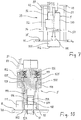
- Fig. 10 shows the here forming the tool to be operated hydraulically screw tensioning cylinder 5, which tightening, especially retightening, and possibly also the release of the in the Figures 1 and 2 reproduced screw 10 is used. Shown is the bolt tensioning cylinder in its operating position before the application of hydraulic pressure. In this position, it is lowered so far that is supported with its bottom 102 on the annular flange 7A.
- a predetermined preload force can be applied to the threaded element 11 in the longitudinal direction of the bolt, as a result of which the threaded element 11 stretches somewhat in order to tighten or retighten the threaded nut 12 of the screw connection.
- a rotatably mounted in a cylinder housing 100 of the screw 5 clamping cylinder sleeve 114 is provided at its one end with an internal thread 116.
- the interchangeable sleeve 114 is screwed before the beginning of the clamping process by turning the interchangeable sleeve 114 on those free threaded end portion 11 A of the threaded member 11, which protrudes upward over the nut 12.
- the exchange socket 114 is also accompanied by a corresponding lowering of the entire bolt tensioning cylinder 5 to the support of the bottom 102 on the annular flange 7A, since the interchangeable bushing has no or only a slight longitudinal clearance relative to the cylinder housing 100.
- the hydraulic tensioning mechanism is located in the pressure-resistant cylinder housing 100.
- This may also be composed of several cylinder sections in a modular manner.
- the rigid continuation of the cylinder housing 100 is a support tube 101. This is either part of the cylinder housing 100, as shown, or a separate component.
- the support tube 101 is open to the screw, surrounds the threaded nut 12 and is supported with the bottom 102 against the top of the annular flange 7A. This therefore forms the abutment during the clamping process.
- the clamping process is carried out by pulling the exchange socket 114 at the threaded end 11A, wherein for tightening the nut 12, this is screwed down until it rests firmly again with its footprint 12A against the flange 7A.
- the support tube 101 is provided with at least one opening which is of such size that the nut 12 can rotate through the opening and thus be retightened. Of course, this is only possible if at the same time the clamping device works, and therefore the nut 12 is not burdened by considerable friction.
- the rotation of the threaded nut 12 is effected by means of a rotary sleeve 110 surrounding the nut.
- the rotary sleeve 110 is driven by a gear 111, which is mounted laterally on the support tube 101 and works through its opening.
- the cylinder housing 100 is provided with a hydraulic connection 112, via which a hydraulic working space 118 in the interior of the tool is connected to a hydraulic pump 86 via the flexible but pressure-resistant hydraulic line 87 ( Fig. 1 ).
- the hydraulic pump 86 is part of the stationary unit 2.
- the piston 115 surrounds the interchangeable bushing 114 in a ring shape.
- the piston 115 is provided at its inner edge with a circumferential step which forms a driver surface 121 on which the interchangeable bushing 114 is supported with a radially widened section 125.
- the exchange socket 114 is entrained by the piston 115. Without pressure load the exchange sleeve 114 is freely rotatable relative to the piston 115 and relative to the cylinder housing 100.
- the change sleeve 114 is located as well as the piston 115 centrally on the longitudinal axis of the cylinder housing 100 and is composed successively from a portion with the internal thread 116 which is screwed onto the threaded end portion 11A of the threaded member 11, from the radially expanded portion 125 and from a Drive section 126.
- the drive section 126 is located on the threaded element 11 facing away from the end of the exchange socket 114th
- the shaft of the electric drive 51 operated in response to tool control signals of the control unit is engaged to rotate the changer sleeve 114, or either, prior to the clamping process, unscrewing the entire cylinder housing 100 onto the threaded end portion 11A the clamping process to unscrew the entire cylinder housing 100 again from the threaded end 11A.
- the controlled, motor-driven screwing on and off the exchange socket 114 is carried out in dependence on tool control signals of the control unit. 4
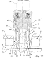
- FIG. 11 shows an embodiment in which the locking against locking retaining tool 70 and the tool 5 are arranged in combination on the carriage or the tool carrier.
- the holding tool 70 is fastened to the tool carrier 20, here on its lower platform 31, and comprises two clamping jaws 130 movable toward each other with respect to the screwing axis. Their ends here form the counter-holding surfaces 75A, 75B, and are designed as shells for this purpose.
- the radius of the shells is substantially equal to the radius of the threaded portion 11A of the threaded member 11.
- the drive of the two jaws 130 takes place electrically, in turn, the control unit 4 ( FIG. 1 ) is adapted to control this drive via the holding tool control signals.
- the control unit 4 FIG. 1
- the control unit 4 is adapted to control this drive via the holding tool control signals.
- the drive of the holding tool 70 must generate relatively high compressive forces.
- the counter-holding surfaces 75A, 75B may have a suitable friction lining, eg rubber, or a suitable non-smooth surface.
- this surface may be matched in its structure to the outer structure of the thread, that a substantial blocking against co-rotation is achieved.
- the jaws 130 of the holding tool 70 extend through openings 131 in the tool 5, wherein the counter-holding surfaces 75 A, 75 B are located within the tool 5.
- the clamping jaws 130 are guided in the holding tool 70 fixedly mounted on the tool carrier in such a way that they are movable exclusively in their clamping direction by means of the drive.
- the openings 131 are located in the support tube 101 of the tool 5. They extend continuously to the bottom 102 of the support tube 101. This ensures that the tool 5, when it is lowered for the clamping process, not by the components of the holding tool 70th is prevented. Although the tool 5 and the holding tool 70 are structurally combined, their functions are separate from each other.
- FIG. 11 makes use of the fact that between the top of the nut 12 and that threaded end portion 11A, which is enclosed by the exchange sleeve 114, in practice, often a threaded longitudinal section of about 5 mm is available. This threaded longitudinal section is sufficient to prevent the co-rotation of the threaded element 11 by means of the clamping jaws 130 moved together there.
- the control unit 4 ( Fig. 1 ) to be trained on traction drive control signals the tool carrier 20 including the screw tensioning cylinder 5 to drive to a working position in which the screw tensioning cylinder 5 opposite the respective screw to be tightened, and tool control signals the axial tightening of the screw and turning the nut 12th to control.
- the control unit 4 ( Fig. 1 ) is configured to control the drive of the holding tool 70 via holding tool control signals.
- Fig. 12 shows a further embodiment.
- the retaining tool 70 which protects against turning, is arranged centrally in the tool 5 designed as a screw-clamping cylinder.
- the bolt tensioning cylinder itself corresponds in its basic construction of the embodiment according to Fig. 10 or Fig. 11 , This applies to the cylinder housing 100, for the guided therein piston, which here is a double piston 115, for the rotating in the cylinder housing exchange sleeve 114 and rotatably disposed in the cylinder housing rotary sleeve 110 for rotating the nut 12th
- Fig. 12 is arranged on the longitudinal axis of the exchange socket 114, a rod 140, to which the exchange socket 114 is provided with a corresponding longitudinal bore.
- the mono- or multipart rod 140 is at its in Fig. 12 lower end provided with the holding tool 70 and is in the range of his in Fig. 12 provided at the top with a rotation 141.
- the anti-rotation 141 holds the rod 140 against rotation relative to the cylinder housing 100.
- the longitudinal groove 143 extends axially only over part of the length of the 140th
- the embodiment Fig. 12 is suitable for such screw in which the threaded member 11 is additionally provided on the front side of its threaded end portion 11A with a polygon 11B.
- the polygon 11B is here an axially projecting square, but can also z. B. a hexagon or a countersunk in the threaded end portion 11 A formed square or hexagon be.
- the holding tool 70 is designed as a corresponding polygon, here so as a square socket, which can be coupled by positive engagement with the polygon 11B. To form the holding tool 70, the lower end of the rod 140 is increased accordingly.
- the holding tool 70 is supported axially and under constant spring force against the polygon 11B.
- the spring force is applied by a spring element 147, which on the one hand against the holding tool 70 or the rod 140, and on the other hand against the exchange socket 114 is supported.
- the spring element 147 provides for a continuous axial biasing force of the holding tool 70, so that after a short relative rotation comes to a secure engagement of the holding tool 70 on the polygon 11B.
- the required axial clearance is ensured by the length of the longitudinal groove 143.
- Fig. 12 is part of the tool 5 of the drive 51 for rotating the removable sleeve 114.
- the drive is not centrally on the longitudinal axis, since there is the rod 140.
- the drive 51 is rather offset laterally, wherein a gear 148 in the drive path between the drive 51 and exchange socket 114 is present.
- Part of the transmission 148 is a gear 149 rotatably fixed to the exchange sleeve 114.
- the gear 149 has a through hole 150, through which the rod 140 extends freely rotatably.
- control unit 4 ( Fig. 1 ) be designed to drive via traction drive control signals the tool carrier 20 including the bolt tensioning cylinder 5 to drive to a working position in which the bolt tensioning cylinder 5 opposite to the respective tightening screw.
- control unit 4 may be designed to control the axial tightening of the screw connection and the rotation of the nut 12 via tool control signals.
- control unit 4 ( Fig. 1 ) be designed to control holding tool control signals and a corresponding drive the holding tool 70 by the rod 140 with the rigidly arranged holding tool 70 controlled by the drive lowered to the screw and controlled raised again.
- the function of the controlled lowering and lifting of the holding tool but can also perform the spring element 147.
Landscapes
- Engineering & Computer Science (AREA)
- Mechanical Engineering (AREA)
- Life Sciences & Earth Sciences (AREA)
- Chemical & Material Sciences (AREA)
- Sustainable Development (AREA)
- Sustainable Energy (AREA)
- Combustion & Propulsion (AREA)
- General Engineering & Computer Science (AREA)
- Architecture (AREA)
- Materials Engineering (AREA)
- Wood Science & Technology (AREA)
- Civil Engineering (AREA)
- Structural Engineering (AREA)
- Details Of Spanners, Wrenches, And Screw Drivers And Accessories (AREA)
- Wind Motors (AREA)
- Jigs For Machine Tools (AREA)
Applications Claiming Priority (1)
| Application Number | Priority Date | Filing Date | Title |
|---|---|---|---|
| DE102018107653.3A DE102018107653A1 (de) | 2018-03-29 | 2018-03-29 | Vorrichtung zum Anziehen von Schraubverbindungen |
Publications (2)
| Publication Number | Publication Date |
|---|---|
| EP3550139A1 true EP3550139A1 (fr) | 2019-10-09 |
| EP3550139B1 EP3550139B1 (fr) | 2020-08-19 |
Family
ID=65817858
Family Applications (1)
| Application Number | Title | Priority Date | Filing Date |
|---|---|---|---|
| EP19163027.6A Active EP3550139B1 (fr) | 2018-03-29 | 2019-03-15 | Dispositif de serrage de raccords vissés |
Country Status (6)
| Country | Link |
|---|---|
| US (1) | US11148240B2 (fr) |
| EP (1) | EP3550139B1 (fr) |
| JP (1) | JP7412892B2 (fr) |
| DE (1) | DE102018107653A1 (fr) |
| DK (1) | DK3550139T3 (fr) |
| ES (1) | ES2827305T3 (fr) |
Cited By (4)
| Publication number | Priority date | Publication date | Assignee | Title |
|---|---|---|---|---|
| CN113977248A (zh) * | 2021-09-27 | 2022-01-28 | 广州东焊智能装备有限公司 | 拧紧装置及拧紧方法 |
| WO2023106911A1 (fr) | 2021-12-09 | 2023-06-15 | Intomechanics B.V. | Machine à auto-centrage pour manipuler des ensembles écrou et boulon |
| NL1044424B1 (en) | 2022-09-26 | 2024-04-03 | Intomechanics B V | Movable bolting tool for manipulating nut and bolt assemblies of a bolted flange assembly |
| WO2025132450A1 (fr) | 2023-12-18 | 2025-06-26 | Intomechanics B.V. | Robot de boulonnage mobile pour manipuler des ensembles écrou et boulon d'un ensemble bride boulonnée |
Families Citing this family (18)
| Publication number | Priority date | Publication date | Assignee | Title |
|---|---|---|---|---|
| GB2580102B (en) * | 2018-12-21 | 2021-08-25 | Caterpillar Energy Solutions Gmbh | System for tensioning at least one connecting element |
| EP3973178B1 (fr) * | 2019-05-21 | 2024-04-24 | Vestas Wind Systems A/S | Procédé permettant d'ériger une tour d'éolienne à l'aide de boulons filetés |
| CN110410283A (zh) * | 2019-07-29 | 2019-11-05 | 浙江未来技术研究院(嘉兴) | 一种螺栓或螺母紧固状态监测方法及系统 |
| CN113048014B (zh) * | 2019-12-27 | 2023-03-31 | 新疆金风科技股份有限公司 | 风力发电机组叶根螺栓紧固控制系统和控制方法 |
| DE102020110895A1 (de) * | 2020-04-22 | 2021-10-28 | SCHAAF GmbH & Co. KG | Verfahren zur Installation und/oder Wartung einer Flanschverbindung sowie Werkzeug und Verwendung |
| CN111571194B (zh) * | 2020-06-04 | 2024-10-29 | 大连泰凯工业有限公司 | 一种快速连接自校正螺栓旋拧机构 |
| CN112720473B (zh) * | 2020-12-22 | 2022-04-19 | 河南科技大学 | 一种薄壁大螺纹件装配的九自由度机器人拧紧控制方法 |
| CN112994772B (zh) * | 2021-03-17 | 2022-12-02 | 南阳理工学院 | 可调式互联网信号中继器 |
| CN115781227B (zh) * | 2022-12-16 | 2025-08-08 | 湖南严格智能技术有限公司 | 用于轧机主轴保护帽拆装及搬运的抓手装置及拆装方法 |
| DE102023119208B3 (de) | 2023-07-20 | 2025-01-02 | Frank Hohmann | Hebe- und Transportvorrichtung |
| CN117072388A (zh) * | 2023-09-04 | 2023-11-17 | 厦门双瑞风电科技有限公司 | 一种防雷装置、风电叶片及安装方法 |
| EP4520960B1 (fr) * | 2023-09-06 | 2026-02-18 | Admede Ab | Outil d'allongement pour allonger une tige filetée ou un boulon d'un raccord à bride |
| AU2024344016A1 (en) * | 2023-09-21 | 2026-04-09 | Total Marine Technology Pty Ltd | Automatic flange bolting robot |
| CN117260245A (zh) * | 2023-10-31 | 2023-12-22 | 中国航发动力股份有限公司 | 一种嵌件自锁螺母拧紧装配系统及方法 |
| DE102024127845B3 (de) * | 2024-09-25 | 2026-01-15 | Wagner Vermögensverwaltungs-GmbH & Co. KG | Hebe- und Transportvorrichtung zum Positionieren einer Schraubvorrichtung |
| CN119388122B (zh) * | 2025-01-02 | 2025-03-14 | 常州市武进区南夏墅宏昊机械设备有限公司 | 一种连接器导向对中控力拧螺母机 |
| CN119703682B (zh) * | 2025-03-03 | 2025-05-23 | 联钢精密科技(中国)有限公司 | 一种具有精确旋转功能的伺服自动送料装置 |
| CN121111852B (zh) * | 2025-11-14 | 2026-03-10 | 长春禹衡光学有限公司 | 组合螺钉及基于组合螺钉的编码器同步转移方法 |
Citations (4)
| Publication number | Priority date | Publication date | Assignee | Title |
|---|---|---|---|---|
| EP2607685A1 (fr) | 2011-12-21 | 2013-06-26 | Kenneth Johst | Robot de montage et serrage de boulons pour éoliennes |
| US20130185932A1 (en) * | 2011-02-01 | 2013-07-25 | Mitsubishi Heavy Industries, Ltd. | Fastening and loosening device |
| EP3195991A1 (fr) * | 2016-01-21 | 2017-07-26 | Admede Ab | Robot avec moyen de positionnement pour déplacer un outil le long d'un joint à brides |
| CN107538210A (zh) * | 2017-09-29 | 2018-01-05 | 新疆金风科技股份有限公司 | 螺栓紧固装置及其操作方法 |
Family Cites Families (11)
| Publication number | Priority date | Publication date | Assignee | Title |
|---|---|---|---|---|
| US4883185A (en) * | 1985-08-28 | 1989-11-28 | The Hokkaido Electric Power Co., Inc. | Suspension type transporter for a bolt drawing machine and positioning controller therefor |
| JPH1110461A (ja) * | 1997-06-17 | 1999-01-19 | Toshiba Corp | ねじの締結装置 |
| JPH1177451A (ja) * | 1997-09-10 | 1999-03-23 | Ngk Insulators Ltd | ネジ部材の締付治具および締付装置 |
| GB0406359D0 (en) * | 2004-03-20 | 2004-04-21 | Gunton Bruce S | Drive arrangement |
| JP5132398B2 (ja) * | 2008-04-10 | 2013-01-30 | 株式会社リコー | パルスコードホイールの製造方法、パルスコードホイール、ロータリーエンコーダ、回転制御装置、ベルト搬送装置、及び画像形成装置 |
| US8965619B2 (en) * | 2010-12-15 | 2015-02-24 | Symbotic, LLC | Bot having high speed stability |
| JP2012157950A (ja) | 2011-02-01 | 2012-08-23 | Mitsubishi Heavy Ind Ltd | ボルトテンショナ |
| DE102012009255A1 (de) * | 2012-05-02 | 2013-11-07 | Jörg Hohmann | Hebe- und Transportvorrichtung |
| JP5650171B2 (ja) | 2012-08-24 | 2015-01-07 | 株式会社日本製鋼所 | ボルトテンショナ |
| DE102015116484A1 (de) * | 2015-09-29 | 2017-03-30 | Jörg Hohmann | Spannvorrichtung für eine Schraubverbindung, Verfahren zum Anziehen einer Schraubverbindung sowie Gewindemutter |
| US10345119B2 (en) * | 2017-01-05 | 2019-07-09 | GM Global Technology Operations LLC | Systems for observing a rotation of a wheel |
-
2018
- 2018-03-29 DE DE102018107653.3A patent/DE102018107653A1/de not_active Withdrawn
-
2019
- 2019-03-15 EP EP19163027.6A patent/EP3550139B1/fr active Active
- 2019-03-15 ES ES19163027T patent/ES2827305T3/es active Active
- 2019-03-15 DK DK19163027.6T patent/DK3550139T3/da active
- 2019-03-29 US US16/368,966 patent/US11148240B2/en active Active
- 2019-03-29 JP JP2019067194A patent/JP7412892B2/ja active Active
Patent Citations (4)
| Publication number | Priority date | Publication date | Assignee | Title |
|---|---|---|---|---|
| US20130185932A1 (en) * | 2011-02-01 | 2013-07-25 | Mitsubishi Heavy Industries, Ltd. | Fastening and loosening device |
| EP2607685A1 (fr) | 2011-12-21 | 2013-06-26 | Kenneth Johst | Robot de montage et serrage de boulons pour éoliennes |
| EP3195991A1 (fr) * | 2016-01-21 | 2017-07-26 | Admede Ab | Robot avec moyen de positionnement pour déplacer un outil le long d'un joint à brides |
| CN107538210A (zh) * | 2017-09-29 | 2018-01-05 | 新疆金风科技股份有限公司 | 螺栓紧固装置及其操作方法 |
Cited By (8)
| Publication number | Priority date | Publication date | Assignee | Title |
|---|---|---|---|---|
| CN113977248A (zh) * | 2021-09-27 | 2022-01-28 | 广州东焊智能装备有限公司 | 拧紧装置及拧紧方法 |
| CN113977248B (zh) * | 2021-09-27 | 2022-06-14 | 广州东焊智能装备有限公司 | 拧紧装置及拧紧方法 |
| WO2023106911A1 (fr) | 2021-12-09 | 2023-06-15 | Intomechanics B.V. | Machine à auto-centrage pour manipuler des ensembles écrou et boulon |
| NL1044234B1 (en) | 2021-12-09 | 2023-06-26 | Intomechanics B V | Self-centering machine for manipulating nut and bolt assemblies |
| NL1044424B1 (en) | 2022-09-26 | 2024-04-03 | Intomechanics B V | Movable bolting tool for manipulating nut and bolt assemblies of a bolted flange assembly |
| WO2024072209A1 (fr) | 2022-09-26 | 2024-04-04 | Intomechanics B.V. | Outil de boulonnage mobile pour manipuler des ensembles écrou et boulon d'un ensemble bride boulonnée |
| WO2025132450A1 (fr) | 2023-12-18 | 2025-06-26 | Intomechanics B.V. | Robot de boulonnage mobile pour manipuler des ensembles écrou et boulon d'un ensemble bride boulonnée |
| NL1044760B1 (nl) | 2023-12-18 | 2025-07-01 | Intomechanics B V | Movable bolting robot for manipulating nut and bolt assemblies of a bolted flange assembly |
Also Published As
| Publication number | Publication date |
|---|---|
| JP7412892B2 (ja) | 2024-01-15 |
| US11148240B2 (en) | 2021-10-19 |
| ES2827305T3 (es) | 2021-05-20 |
| JP2019171565A (ja) | 2019-10-10 |
| DE102018107653A1 (de) | 2019-10-02 |
| DK3550139T3 (da) | 2020-11-09 |
| EP3550139B1 (fr) | 2020-08-19 |
| US20190299346A1 (en) | 2019-10-03 |
Similar Documents
| Publication | Publication Date | Title |
|---|---|---|
| EP3550139B1 (fr) | Dispositif de serrage de raccords vissés | |
| EP3546116B2 (fr) | Dispositif de serrage de raccords vissés | |
| EP3871829B1 (fr) | Procédé de serrage de raccords à vis, dispositif à vis multiples | |
| EP2394800B1 (fr) | Dispositif de saisie et de levage d'objets | |
| DE102009010280B4 (de) | Mechanisches Bearbeitungsstations-Teileträger-Hubwerk | |
| DE102004043146B3 (de) | Hydraulische Schraubenspannvorrichtung | |
| DE4109888A1 (de) | Vorrichtung zur halterung und fuehrung einer achse oder welle oder eines lagerrings | |
| DE102016107451A1 (de) | Selbstfahrende Transport- und Hubfahreinheit und Verfahren zum Bewegen von Objekten mittels der Transport- und Hubfahreinheit | |
| EP2821182B1 (fr) | Dispositif de serrage pour l'étirement d'un boulon fileté | |
| DE2916312A1 (de) | Greifzange fuer handhabungsgeraete | |
| EP1423231A1 (fr) | Poste de vissage | |
| DE60103475T2 (de) | Maschine zum Einschrauben oder Ausschrauben der Bolzen bzw. der Schienenschrauben von geschraubten Klemmeinrichtungen von Eisenbahngleisen | |
| EP1363063B1 (fr) | Lubricateur | |
| DE3142378A1 (de) | "maschine zur selbsttaetigen montage von reifen auf felgen" | |
| EP0320498A2 (fr) | Robot industriel | |
| DE68907165T2 (de) | Vorrichtung zum Aufschrauben und Abschrauben mindestens einer Mutter auf Verbindungselemente. | |
| DE4433731C2 (de) | Schraubvorrichtung | |
| DE2618877C3 (de) | Vorrichtung zum Kontern und Brechen der Gewindeverbindungen zwischen Rohrkörpern | |
| DE202010008450U1 (de) | Handhabungsgerät für Spaltbandringe | |
| DE102006062771B4 (de) | Hubstützenbock, insbesondere für einen Universaltragrahmen | |
| DE4113847C1 (en) | Coupling releasably joining top end of string section with rotary drive pipe hole - uses coupling lever on axis at right angles to radial plane running through lever and rotation axis of drive pipe | |
| EP2933219A1 (fr) | Dispositif de serrage pour câbles | |
| EP3042735A1 (fr) | Dispositif d'entretien d'amortisseurs de chocs | |
| DE2229073C2 (de) | Vorrichtung zum gleichzeitigen Spannen mehrerer Schraubenbolzen, Dehnschrauben, Zuganker oder dergleichen | |
| DE19860703A1 (de) | Transportsystem |
Legal Events
| Date | Code | Title | Description |
|---|---|---|---|
| PUAI | Public reference made under article 153(3) epc to a published international application that has entered the european phase |
Free format text: ORIGINAL CODE: 0009012 |
|
| STAA | Information on the status of an ep patent application or granted ep patent |
Free format text: STATUS: THE APPLICATION HAS BEEN PUBLISHED |
|
| AK | Designated contracting states |
Kind code of ref document: A1 Designated state(s): AL AT BE BG CH CY CZ DE DK EE ES FI FR GB GR HR HU IE IS IT LI LT LU LV MC MK MT NL NO PL PT RO RS SE SI SK SM TR |
|
| AX | Request for extension of the european patent |
Extension state: BA ME |
|
| STAA | Information on the status of an ep patent application or granted ep patent |
Free format text: STATUS: REQUEST FOR EXAMINATION WAS MADE |
|
| 17P | Request for examination filed |
Effective date: 20191028 |
|
| RBV | Designated contracting states (corrected) |
Designated state(s): AL AT BE BG CH CY CZ DE DK EE ES FI FR GB GR HR HU IE IS IT LI LT LU LV MC MK MT NL NO PL PT RO RS SE SI SK SM TR |
|
| REG | Reference to a national code |
Ref country code: DE Ref legal event code: R079 Ref document number: 502019000152 Country of ref document: DE Free format text: PREVIOUS MAIN CLASS: F03D0013200000 Ipc: B23P0019060000 |
|
| GRAP | Despatch of communication of intention to grant a patent |
Free format text: ORIGINAL CODE: EPIDOSNIGR1 |
|
| STAA | Information on the status of an ep patent application or granted ep patent |
Free format text: STATUS: GRANT OF PATENT IS INTENDED |
|
| RIC1 | Information provided on ipc code assigned before grant |
Ipc: E04H 12/08 20060101ALI20191213BHEP Ipc: B23P 19/06 20060101AFI20191213BHEP Ipc: F03D 13/10 20160101ALI20191213BHEP Ipc: F03D 13/20 20160101ALI20191213BHEP Ipc: B25B 29/02 20060101ALI20191213BHEP |
|
| INTG | Intention to grant announced |
Effective date: 20200120 |
|
| GRAS | Grant fee paid |
Free format text: ORIGINAL CODE: EPIDOSNIGR3 |
|
| GRAA | (expected) grant |
Free format text: ORIGINAL CODE: 0009210 |
|
| STAA | Information on the status of an ep patent application or granted ep patent |
Free format text: STATUS: THE PATENT HAS BEEN GRANTED |
|
| AK | Designated contracting states |
Kind code of ref document: B1 Designated state(s): AL AT BE BG CH CY CZ DE DK EE ES FI FR GB GR HR HU IE IS IT LI LT LU LV MC MK MT NL NO PL PT RO RS SE SI SK SM TR |
|
| REG | Reference to a national code |
Ref country code: CH Ref legal event code: EP |
|
| REG | Reference to a national code |
Ref country code: DE Ref legal event code: R096 Ref document number: 502019000152 Country of ref document: DE |
|
| REG | Reference to a national code |
Ref country code: AT Ref legal event code: REF Ref document number: 1303394 Country of ref document: AT Kind code of ref document: T Effective date: 20200915 |
|
| REG | Reference to a national code |
Ref country code: IE Ref legal event code: FG4D Free format text: LANGUAGE OF EP DOCUMENT: GERMAN |
|
| REG | Reference to a national code |
Ref country code: DE Ref legal event code: R082 Ref document number: 502019000152 Country of ref document: DE Representative=s name: JANKE SCHOLL PATENTANWAELTE PARTG MBB, DE Ref country code: DE Ref legal event code: R082 Ref document number: 502019000152 Country of ref document: DE Representative=s name: CHRISTOPHERSEN PATENTANWAELTE, DE Ref country code: DE Ref legal event code: R082 Ref document number: 502019000152 Country of ref document: DE Representative=s name: CHRISTOPHERSEN & PARTNER PARTNERSCHAFT MBB PAT, DE |
|
| REG | Reference to a national code |
Ref country code: DK Ref legal event code: T3 Effective date: 20201103 |
|
| REG | Reference to a national code |
Ref country code: LT Ref legal event code: MG4D |
|
| REG | Reference to a national code |
Ref country code: NL Ref legal event code: MP Effective date: 20200819 |
|
| PG25 | Lapsed in a contracting state [announced via postgrant information from national office to epo] |
Ref country code: NO Free format text: LAPSE BECAUSE OF FAILURE TO SUBMIT A TRANSLATION OF THE DESCRIPTION OR TO PAY THE FEE WITHIN THE PRESCRIBED TIME-LIMIT Effective date: 20201119 Ref country code: BG Free format text: LAPSE BECAUSE OF FAILURE TO SUBMIT A TRANSLATION OF THE DESCRIPTION OR TO PAY THE FEE WITHIN THE PRESCRIBED TIME-LIMIT Effective date: 20201119 Ref country code: PT Free format text: LAPSE BECAUSE OF FAILURE TO SUBMIT A TRANSLATION OF THE DESCRIPTION OR TO PAY THE FEE WITHIN THE PRESCRIBED TIME-LIMIT Effective date: 20201221 Ref country code: FI Free format text: LAPSE BECAUSE OF FAILURE TO SUBMIT A TRANSLATION OF THE DESCRIPTION OR TO PAY THE FEE WITHIN THE PRESCRIBED TIME-LIMIT Effective date: 20200819 Ref country code: LT Free format text: LAPSE BECAUSE OF FAILURE TO SUBMIT A TRANSLATION OF THE DESCRIPTION OR TO PAY THE FEE WITHIN THE PRESCRIBED TIME-LIMIT Effective date: 20200819 Ref country code: HR Free format text: LAPSE BECAUSE OF FAILURE TO SUBMIT A TRANSLATION OF THE DESCRIPTION OR TO PAY THE FEE WITHIN THE PRESCRIBED TIME-LIMIT Effective date: 20200819 Ref country code: SE Free format text: LAPSE BECAUSE OF FAILURE TO SUBMIT A TRANSLATION OF THE DESCRIPTION OR TO PAY THE FEE WITHIN THE PRESCRIBED TIME-LIMIT Effective date: 20200819 |
|
| PG25 | Lapsed in a contracting state [announced via postgrant information from national office to epo] |
Ref country code: LV Free format text: LAPSE BECAUSE OF FAILURE TO SUBMIT A TRANSLATION OF THE DESCRIPTION OR TO PAY THE FEE WITHIN THE PRESCRIBED TIME-LIMIT Effective date: 20200819 Ref country code: RS Free format text: LAPSE BECAUSE OF FAILURE TO SUBMIT A TRANSLATION OF THE DESCRIPTION OR TO PAY THE FEE WITHIN THE PRESCRIBED TIME-LIMIT Effective date: 20200819 Ref country code: PL Free format text: LAPSE BECAUSE OF FAILURE TO SUBMIT A TRANSLATION OF THE DESCRIPTION OR TO PAY THE FEE WITHIN THE PRESCRIBED TIME-LIMIT Effective date: 20200819 Ref country code: NL Free format text: LAPSE BECAUSE OF FAILURE TO SUBMIT A TRANSLATION OF THE DESCRIPTION OR TO PAY THE FEE WITHIN THE PRESCRIBED TIME-LIMIT Effective date: 20200819 Ref country code: IS Free format text: LAPSE BECAUSE OF FAILURE TO SUBMIT A TRANSLATION OF THE DESCRIPTION OR TO PAY THE FEE WITHIN THE PRESCRIBED TIME-LIMIT Effective date: 20201219 |
|
| PG25 | Lapsed in a contracting state [announced via postgrant information from national office to epo] |
Ref country code: EE Free format text: LAPSE BECAUSE OF FAILURE TO SUBMIT A TRANSLATION OF THE DESCRIPTION OR TO PAY THE FEE WITHIN THE PRESCRIBED TIME-LIMIT Effective date: 20200819 Ref country code: RO Free format text: LAPSE BECAUSE OF FAILURE TO SUBMIT A TRANSLATION OF THE DESCRIPTION OR TO PAY THE FEE WITHIN THE PRESCRIBED TIME-LIMIT Effective date: 20200819 Ref country code: CZ Free format text: LAPSE BECAUSE OF FAILURE TO SUBMIT A TRANSLATION OF THE DESCRIPTION OR TO PAY THE FEE WITHIN THE PRESCRIBED TIME-LIMIT Effective date: 20200819 Ref country code: SM Free format text: LAPSE BECAUSE OF FAILURE TO SUBMIT A TRANSLATION OF THE DESCRIPTION OR TO PAY THE FEE WITHIN THE PRESCRIBED TIME-LIMIT Effective date: 20200819 |
|
| REG | Reference to a national code |
Ref country code: ES Ref legal event code: FG2A Ref document number: 2827305 Country of ref document: ES Kind code of ref document: T3 Effective date: 20210520 Ref country code: DE Ref legal event code: R097 Ref document number: 502019000152 Country of ref document: DE |
|
| PG25 | Lapsed in a contracting state [announced via postgrant information from national office to epo] |
Ref country code: AL Free format text: LAPSE BECAUSE OF FAILURE TO SUBMIT A TRANSLATION OF THE DESCRIPTION OR TO PAY THE FEE WITHIN THE PRESCRIBED TIME-LIMIT Effective date: 20200819 |
|
| PLBE | No opposition filed within time limit |
Free format text: ORIGINAL CODE: 0009261 |
|
| STAA | Information on the status of an ep patent application or granted ep patent |
Free format text: STATUS: NO OPPOSITION FILED WITHIN TIME LIMIT |
|
| PG25 | Lapsed in a contracting state [announced via postgrant information from national office to epo] |
Ref country code: SK Free format text: LAPSE BECAUSE OF FAILURE TO SUBMIT A TRANSLATION OF THE DESCRIPTION OR TO PAY THE FEE WITHIN THE PRESCRIBED TIME-LIMIT Effective date: 20200819 |
|
| 26N | No opposition filed |
Effective date: 20210520 |
|
| PG25 | Lapsed in a contracting state [announced via postgrant information from national office to epo] |
Ref country code: IT Free format text: LAPSE BECAUSE OF FAILURE TO SUBMIT A TRANSLATION OF THE DESCRIPTION OR TO PAY THE FEE WITHIN THE PRESCRIBED TIME-LIMIT Effective date: 20200819 |
|
| PG25 | Lapsed in a contracting state [announced via postgrant information from national office to epo] |
Ref country code: SI Free format text: LAPSE BECAUSE OF FAILURE TO SUBMIT A TRANSLATION OF THE DESCRIPTION OR TO PAY THE FEE WITHIN THE PRESCRIBED TIME-LIMIT Effective date: 20200819 |
|
| PG25 | Lapsed in a contracting state [announced via postgrant information from national office to epo] |
Ref country code: MC Free format text: LAPSE BECAUSE OF FAILURE TO SUBMIT A TRANSLATION OF THE DESCRIPTION OR TO PAY THE FEE WITHIN THE PRESCRIBED TIME-LIMIT Effective date: 20200819 |
|
| REG | Reference to a national code |
Ref country code: BE Ref legal event code: MM Effective date: 20210331 |
|
| REG | Reference to a national code |
Ref country code: DE Ref legal event code: R082 Ref document number: 502019000152 Country of ref document: DE Representative=s name: JANKE SCHOLL PATENTANWAELTE PARTG MBB, DE |
|
| PG25 | Lapsed in a contracting state [announced via postgrant information from national office to epo] |
Ref country code: IE Free format text: LAPSE BECAUSE OF NON-PAYMENT OF DUE FEES Effective date: 20210315 Ref country code: LU Free format text: LAPSE BECAUSE OF NON-PAYMENT OF DUE FEES Effective date: 20210315 Ref country code: FR Free format text: LAPSE BECAUSE OF NON-PAYMENT OF DUE FEES Effective date: 20210331 |
|
| PG25 | Lapsed in a contracting state [announced via postgrant information from national office to epo] |
Ref country code: BE Free format text: LAPSE BECAUSE OF NON-PAYMENT OF DUE FEES Effective date: 20210331 |
|
| REG | Reference to a national code |
Ref country code: CH Ref legal event code: PL |
|
| PG25 | Lapsed in a contracting state [announced via postgrant information from national office to epo] |
Ref country code: LI Free format text: LAPSE BECAUSE OF NON-PAYMENT OF DUE FEES Effective date: 20220331 Ref country code: CH Free format text: LAPSE BECAUSE OF NON-PAYMENT OF DUE FEES Effective date: 20220331 |
|
| PG25 | Lapsed in a contracting state [announced via postgrant information from national office to epo] |
Ref country code: CY Free format text: LAPSE BECAUSE OF FAILURE TO SUBMIT A TRANSLATION OF THE DESCRIPTION OR TO PAY THE FEE WITHIN THE PRESCRIBED TIME-LIMIT Effective date: 20200819 |
|
| P01 | Opt-out of the competence of the unified patent court (upc) registered |
Effective date: 20230530 |
|
| PG25 | Lapsed in a contracting state [announced via postgrant information from national office to epo] |
Ref country code: HU Free format text: LAPSE BECAUSE OF FAILURE TO SUBMIT A TRANSLATION OF THE DESCRIPTION OR TO PAY THE FEE WITHIN THE PRESCRIBED TIME-LIMIT; INVALID AB INITIO Effective date: 20190315 Ref country code: GR Free format text: LAPSE BECAUSE OF FAILURE TO SUBMIT A TRANSLATION OF THE DESCRIPTION OR TO PAY THE FEE WITHIN THE PRESCRIBED TIME-LIMIT Effective date: 20200819 |
|
| PG25 | Lapsed in a contracting state [announced via postgrant information from national office to epo] |
Ref country code: MK Free format text: LAPSE BECAUSE OF FAILURE TO SUBMIT A TRANSLATION OF THE DESCRIPTION OR TO PAY THE FEE WITHIN THE PRESCRIBED TIME-LIMIT Effective date: 20200819 |
|
| PG25 | Lapsed in a contracting state [announced via postgrant information from national office to epo] |
Ref country code: TR Free format text: LAPSE BECAUSE OF FAILURE TO SUBMIT A TRANSLATION OF THE DESCRIPTION OR TO PAY THE FEE WITHIN THE PRESCRIBED TIME-LIMIT Effective date: 20200819 |
|
| PG25 | Lapsed in a contracting state [announced via postgrant information from national office to epo] |
Ref country code: MT Free format text: LAPSE BECAUSE OF FAILURE TO SUBMIT A TRANSLATION OF THE DESCRIPTION OR TO PAY THE FEE WITHIN THE PRESCRIBED TIME-LIMIT Effective date: 20200819 |
|
| REG | Reference to a national code |
Ref country code: AT Ref legal event code: MM01 Ref document number: 1303394 Country of ref document: AT Kind code of ref document: T Effective date: 20240315 |
|
| PGFP | Annual fee paid to national office [announced via postgrant information from national office to epo] |
Ref country code: ES Payment date: 20250429 Year of fee payment: 7 |
|
| PG25 | Lapsed in a contracting state [announced via postgrant information from national office to epo] |
Ref country code: AT Free format text: LAPSE BECAUSE OF NON-PAYMENT OF DUE FEES Effective date: 20240315 |
|
| PGFP | Annual fee paid to national office [announced via postgrant information from national office to epo] |
Ref country code: GB Payment date: 20260324 Year of fee payment: 8 |
|
| PGFP | Annual fee paid to national office [announced via postgrant information from national office to epo] |
Ref country code: DE Payment date: 20260319 Year of fee payment: 8 Ref country code: DK Payment date: 20260324 Year of fee payment: 8 |
|
| PGFP | Annual fee paid to national office [announced via postgrant information from national office to epo] |
Ref country code: AT Payment date: 20260410 Year of fee payment: 5 |