EP3550143A1 - Compresseur de fluide frigorigène et appareil de réfrigération/stockage de froid dans lequel celui-ci est utilisé - Google Patents
Compresseur de fluide frigorigène et appareil de réfrigération/stockage de froid dans lequel celui-ci est utilisé Download PDFInfo
- Publication number
- EP3550143A1 EP3550143A1 EP17877109.3A EP17877109A EP3550143A1 EP 3550143 A1 EP3550143 A1 EP 3550143A1 EP 17877109 A EP17877109 A EP 17877109A EP 3550143 A1 EP3550143 A1 EP 3550143A1
- Authority
- EP
- European Patent Office
- Prior art keywords
- refrigerant compressor
- oxide film
- shaft
- lubricating oil
- bearing
- Prior art date
- Legal status (The legal status is an assumption and is not a legal conclusion. Google has not performed a legal analysis and makes no representation as to the accuracy of the status listed.)
- Withdrawn
Links
- 239000003507 refrigerant Substances 0.000 title claims abstract description 106
- 238000003860 storage Methods 0.000 title description 8
- 238000005057 refrigeration Methods 0.000 title description 3
- 239000010687 lubricating oil Substances 0.000 claims abstract description 69
- 230000006835 compression Effects 0.000 claims abstract description 13
- 238000007906 compression Methods 0.000 claims abstract description 13
- 239000000463 material Substances 0.000 claims description 72
- 239000005069 Extreme pressure additive Substances 0.000 claims description 39
- 239000013078 crystal Substances 0.000 claims description 39
- XEEYBQQBJWHFJM-UHFFFAOYSA-N Iron Chemical compound [Fe] XEEYBQQBJWHFJM-UHFFFAOYSA-N 0.000 claims description 37
- 239000003795 chemical substances by application Substances 0.000 claims description 19
- JEIPFZHSYJVQDO-UHFFFAOYSA-N ferric oxide Chemical compound O=[Fe]O[Fe]=O JEIPFZHSYJVQDO-UHFFFAOYSA-N 0.000 claims description 16
- 229910052742 iron Inorganic materials 0.000 claims description 16
- 239000003921 oil Substances 0.000 claims description 14
- 239000010696 ester oil Substances 0.000 claims description 13
- 239000006096 absorbing agent Substances 0.000 claims description 11
- 239000002480 mineral oil Substances 0.000 claims description 11
- 235000010446 mineral oil Nutrition 0.000 claims description 11
- 150000004996 alkyl benzenes Chemical class 0.000 claims description 7
- -1 phosphorus compound Chemical class 0.000 claims description 5
- 229910052698 phosphorus Inorganic materials 0.000 claims description 4
- 239000011574 phosphorus Substances 0.000 claims description 4
- XUIMIQQOPSSXEZ-UHFFFAOYSA-N Silicon Chemical compound [Si] XUIMIQQOPSSXEZ-UHFFFAOYSA-N 0.000 description 65
- 229910052710 silicon Inorganic materials 0.000 description 65
- 239000010703 silicon Substances 0.000 description 65
- 238000005299 abrasion Methods 0.000 description 33
- UQSXHKLRYXJYBZ-UHFFFAOYSA-N Iron oxide Chemical group [Fe]=O UQSXHKLRYXJYBZ-UHFFFAOYSA-N 0.000 description 26
- SZVJSHCCFOBDDC-UHFFFAOYSA-N ferrosoferric oxide Chemical compound O=[Fe]O[Fe]O[Fe]=O SZVJSHCCFOBDDC-UHFFFAOYSA-N 0.000 description 25
- 239000010410 layer Substances 0.000 description 24
- 239000000126 substance Substances 0.000 description 20
- VYPSYNLAJGMNEJ-UHFFFAOYSA-N Silicium dioxide Chemical compound O=[Si]=O VYPSYNLAJGMNEJ-UHFFFAOYSA-N 0.000 description 16
- 238000000034 method Methods 0.000 description 13
- 239000000203 mixture Substances 0.000 description 13
- 229910001018 Cast iron Inorganic materials 0.000 description 12
- 150000001875 compounds Chemical class 0.000 description 10
- 230000000694 effects Effects 0.000 description 10
- 229910052840 fayalite Inorganic materials 0.000 description 8
- 238000005259 measurement Methods 0.000 description 8
- 238000007254 oxidation reaction Methods 0.000 description 8
- 230000001603 reducing effect Effects 0.000 description 8
- 239000000377 silicon dioxide Substances 0.000 description 8
- QVGXLLKOCUKJST-UHFFFAOYSA-N atomic oxygen Chemical compound [O] QVGXLLKOCUKJST-UHFFFAOYSA-N 0.000 description 7
- 230000005540 biological transmission Effects 0.000 description 7
- 229910052760 oxygen Inorganic materials 0.000 description 7
- 239000001301 oxygen Substances 0.000 description 7
- 229910001060 Gray iron Inorganic materials 0.000 description 6
- 238000002149 energy-dispersive X-ray emission spectroscopy Methods 0.000 description 6
- 239000011800 void material Substances 0.000 description 6
- 239000007789 gas Substances 0.000 description 5
- 239000000654 additive Substances 0.000 description 4
- 230000003647 oxidation Effects 0.000 description 4
- 235000012239 silicon dioxide Nutrition 0.000 description 4
- 230000007480 spreading Effects 0.000 description 4
- 238000003892 spreading Methods 0.000 description 4
- YSMRWXYRXBRSND-UHFFFAOYSA-N TOTP Chemical compound CC1=CC=CC=C1OP(=O)(OC=1C(=CC=CC=1)C)OC1=CC=CC=C1C YSMRWXYRXBRSND-UHFFFAOYSA-N 0.000 description 3
- 230000007423 decrease Effects 0.000 description 3
- 150000002148 esters Chemical class 0.000 description 3
- 229910052751 metal Inorganic materials 0.000 description 3
- 239000002184 metal Substances 0.000 description 3
- 230000001590 oxidative effect Effects 0.000 description 3
- 230000002093 peripheral effect Effects 0.000 description 3
- 239000004215 Carbon black (E152) Substances 0.000 description 2
- CURLTUGMZLYLDI-UHFFFAOYSA-N Carbon dioxide Chemical compound O=C=O CURLTUGMZLYLDI-UHFFFAOYSA-N 0.000 description 2
- 229910001141 Ductile iron Inorganic materials 0.000 description 2
- 229910019142 PO4 Inorganic materials 0.000 description 2
- 229910000831 Steel Inorganic materials 0.000 description 2
- 238000004458 analytical method Methods 0.000 description 2
- 230000015572 biosynthetic process Effects 0.000 description 2
- 229910001567 cementite Inorganic materials 0.000 description 2
- 230000008878 coupling Effects 0.000 description 2
- 238000010168 coupling process Methods 0.000 description 2
- 238000005859 coupling reaction Methods 0.000 description 2
- 235000014113 dietary fatty acids Nutrition 0.000 description 2
- 238000009792 diffusion process Methods 0.000 description 2
- 239000000194 fatty acid Substances 0.000 description 2
- 229930195729 fatty acid Natural products 0.000 description 2
- 150000004665 fatty acids Chemical class 0.000 description 2
- 229930195733 hydrocarbon Natural products 0.000 description 2
- 150000002430 hydrocarbons Chemical class 0.000 description 2
- 238000007373 indentation Methods 0.000 description 2
- 238000007541 indentation hardness test Methods 0.000 description 2
- 239000003112 inhibitor Substances 0.000 description 2
- 150000002500 ions Chemical class 0.000 description 2
- KSOKAHYVTMZFBJ-UHFFFAOYSA-N iron;methane Chemical compound C.[Fe].[Fe].[Fe] KSOKAHYVTMZFBJ-UHFFFAOYSA-N 0.000 description 2
- 230000001050 lubricating effect Effects 0.000 description 2
- 238000005192 partition Methods 0.000 description 2
- NBIIXXVUZAFLBC-UHFFFAOYSA-K phosphate Chemical compound [O-]P([O-])([O-])=O NBIIXXVUZAFLBC-UHFFFAOYSA-K 0.000 description 2
- 239000010452 phosphate Substances 0.000 description 2
- 230000009467 reduction Effects 0.000 description 2
- 239000006104 solid solution Substances 0.000 description 2
- 239000010959 steel Substances 0.000 description 2
- 230000001629 suppression Effects 0.000 description 2
- 238000012360 testing method Methods 0.000 description 2
- STCOOQWBFONSKY-UHFFFAOYSA-N tributyl phosphate Chemical compound CCCCOP(=O)(OCCCC)OCCCC STCOOQWBFONSKY-UHFFFAOYSA-N 0.000 description 2
- OKTJSMMVPCPJKN-UHFFFAOYSA-N Carbon Chemical compound [C] OKTJSMMVPCPJKN-UHFFFAOYSA-N 0.000 description 1
- ZAMOUSCENKQFHK-UHFFFAOYSA-N Chlorine atom Chemical compound [Cl] ZAMOUSCENKQFHK-UHFFFAOYSA-N 0.000 description 1
- LFQSCWFLJHTTHZ-UHFFFAOYSA-N Ethanol Chemical compound CCO LFQSCWFLJHTTHZ-UHFFFAOYSA-N 0.000 description 1
- YCKRFDGAMUMZLT-UHFFFAOYSA-N Fluorine atom Chemical compound [F] YCKRFDGAMUMZLT-UHFFFAOYSA-N 0.000 description 1
- UFHFLCQGNIYNRP-UHFFFAOYSA-N Hydrogen Chemical compound [H][H] UFHFLCQGNIYNRP-UHFFFAOYSA-N 0.000 description 1
- 230000002159 abnormal effect Effects 0.000 description 1
- 239000002253 acid Substances 0.000 description 1
- 239000000853 adhesive Substances 0.000 description 1
- 230000001070 adhesive effect Effects 0.000 description 1
- 229910045601 alloy Inorganic materials 0.000 description 1
- 239000000956 alloy Substances 0.000 description 1
- 229910052782 aluminium Inorganic materials 0.000 description 1
- XAGFODPZIPBFFR-UHFFFAOYSA-N aluminium Chemical compound [Al] XAGFODPZIPBFFR-UHFFFAOYSA-N 0.000 description 1
- 239000002518 antifoaming agent Substances 0.000 description 1
- 230000004888 barrier function Effects 0.000 description 1
- 229910052799 carbon Inorganic materials 0.000 description 1
- 229910002092 carbon dioxide Inorganic materials 0.000 description 1
- 239000001569 carbon dioxide Substances 0.000 description 1
- 238000005266 casting Methods 0.000 description 1
- 239000000460 chlorine Substances 0.000 description 1
- 229910052801 chlorine Inorganic materials 0.000 description 1
- 238000001816 cooling Methods 0.000 description 1
- 238000005260 corrosion Methods 0.000 description 1
- 230000007797 corrosion Effects 0.000 description 1
- 230000007547 defect Effects 0.000 description 1
- 238000001514 detection method Methods 0.000 description 1
- 238000010586 diagram Methods 0.000 description 1
- 239000002270 dispersing agent Substances 0.000 description 1
- 230000009189 diving Effects 0.000 description 1
- 238000011156 evaluation Methods 0.000 description 1
- 239000011737 fluorine Substances 0.000 description 1
- 229910052731 fluorine Inorganic materials 0.000 description 1
- 239000002803 fossil fuel Substances 0.000 description 1
- 229910021385 hard carbon Inorganic materials 0.000 description 1
- 239000001257 hydrogen Substances 0.000 description 1
- 229910052739 hydrogen Inorganic materials 0.000 description 1
- 230000006872 improvement Effects 0.000 description 1
- 239000012535 impurity Substances 0.000 description 1
- 230000000415 inactivating effect Effects 0.000 description 1
- 238000009413 insulation Methods 0.000 description 1
- 235000000396 iron Nutrition 0.000 description 1
- LIKBJVNGSGBSGK-UHFFFAOYSA-N iron(3+);oxygen(2-) Chemical compound [O-2].[O-2].[O-2].[Fe+3].[Fe+3] LIKBJVNGSGBSGK-UHFFFAOYSA-N 0.000 description 1
- 238000003475 lamination Methods 0.000 description 1
- 238000004519 manufacturing process Methods 0.000 description 1
- 238000000691 measurement method Methods 0.000 description 1
- 239000007769 metal material Substances 0.000 description 1
- 238000012986 modification Methods 0.000 description 1
- 230000004048 modification Effects 0.000 description 1
- 150000003018 phosphorus compounds Chemical class 0.000 description 1
- 230000000704 physical effect Effects 0.000 description 1
- 238000005498 polishing Methods 0.000 description 1
- 238000002407 reforming Methods 0.000 description 1
- 239000011347 resin Substances 0.000 description 1
- 229920005989 resin Polymers 0.000 description 1
- 238000000926 separation method Methods 0.000 description 1
- 239000002356 single layer Substances 0.000 description 1
- 239000000344 soap Substances 0.000 description 1
- 239000000243 solution Substances 0.000 description 1
- 238000004611 spectroscopical analysis Methods 0.000 description 1
- 150000003464 sulfur compounds Chemical class 0.000 description 1
- 238000004381 surface treatment Methods 0.000 description 1
- XZZNDPSIHUTMOC-UHFFFAOYSA-N triphenyl phosphate Chemical compound C=1C=CC=CC=1OP(OC=1C=CC=CC=1)(=O)OC1=CC=CC=C1 XZZNDPSIHUTMOC-UHFFFAOYSA-N 0.000 description 1
Images


Classifications
-
- C—CHEMISTRY; METALLURGY
- C10—PETROLEUM, GAS OR COKE INDUSTRIES; TECHNICAL GASES CONTAINING CARBON MONOXIDE; FUELS; LUBRICANTS; PEAT
- C10M—LUBRICATING COMPOSITIONS; USE OF CHEMICAL SUBSTANCES EITHER ALONE OR AS LUBRICATING INGREDIENTS IN A LUBRICATING COMPOSITION
- C10M101/00—Lubricating compositions characterised by the base-material being a mineral or fatty oil
-
- C—CHEMISTRY; METALLURGY
- C10—PETROLEUM, GAS OR COKE INDUSTRIES; TECHNICAL GASES CONTAINING CARBON MONOXIDE; FUELS; LUBRICANTS; PEAT
- C10M—LUBRICATING COMPOSITIONS; USE OF CHEMICAL SUBSTANCES EITHER ALONE OR AS LUBRICATING INGREDIENTS IN A LUBRICATING COMPOSITION
- C10M105/00—Lubricating compositions characterised by the base-material being a non-macromolecular organic compound
- C10M105/02—Well-defined hydrocarbons
- C10M105/06—Well-defined hydrocarbons aromatic
-
- C—CHEMISTRY; METALLURGY
- C10—PETROLEUM, GAS OR COKE INDUSTRIES; TECHNICAL GASES CONTAINING CARBON MONOXIDE; FUELS; LUBRICANTS; PEAT
- C10M—LUBRICATING COMPOSITIONS; USE OF CHEMICAL SUBSTANCES EITHER ALONE OR AS LUBRICATING INGREDIENTS IN A LUBRICATING COMPOSITION
- C10M105/00—Lubricating compositions characterised by the base-material being a non-macromolecular organic compound
- C10M105/08—Lubricating compositions characterised by the base-material being a non-macromolecular organic compound containing oxygen
- C10M105/32—Esters
-
- C—CHEMISTRY; METALLURGY
- C10—PETROLEUM, GAS OR COKE INDUSTRIES; TECHNICAL GASES CONTAINING CARBON MONOXIDE; FUELS; LUBRICANTS; PEAT
- C10M—LUBRICATING COMPOSITIONS; USE OF CHEMICAL SUBSTANCES EITHER ALONE OR AS LUBRICATING INGREDIENTS IN A LUBRICATING COMPOSITION
- C10M137/00—Lubricating compositions characterised by the additive being an organic non-macromolecular compound containing phosphorus
- C10M137/02—Lubricating compositions characterised by the additive being an organic non-macromolecular compound containing phosphorus having no phosphorus-to-carbon bond
- C10M137/04—Phosphate esters
-
- C—CHEMISTRY; METALLURGY
- C10—PETROLEUM, GAS OR COKE INDUSTRIES; TECHNICAL GASES CONTAINING CARBON MONOXIDE; FUELS; LUBRICANTS; PEAT
- C10M—LUBRICATING COMPOSITIONS; USE OF CHEMICAL SUBSTANCES EITHER ALONE OR AS LUBRICATING INGREDIENTS IN A LUBRICATING COMPOSITION
- C10M169/00—Lubricating compositions characterised by containing as components a mixture of at least two types of ingredient selected from base-materials, thickeners or additives, covered by the preceding groups, each of these compounds being essential
- C10M169/04—Mixtures of base-materials and additives
-
- F—MECHANICAL ENGINEERING; LIGHTING; HEATING; WEAPONS; BLASTING
- F04—POSITIVE - DISPLACEMENT MACHINES FOR LIQUIDS; PUMPS FOR LIQUIDS OR ELASTIC FLUIDS
- F04B—POSITIVE-DISPLACEMENT MACHINES FOR LIQUIDS; PUMPS
- F04B17/00—Pumps characterised by combination with, or adaptation to, specific driving engines or motors
- F04B17/03—Pumps characterised by combination with, or adaptation to, specific driving engines or motors driven by electric motors
-
- F—MECHANICAL ENGINEERING; LIGHTING; HEATING; WEAPONS; BLASTING
- F04—POSITIVE - DISPLACEMENT MACHINES FOR LIQUIDS; PUMPS FOR LIQUIDS OR ELASTIC FLUIDS
- F04B—POSITIVE-DISPLACEMENT MACHINES FOR LIQUIDS; PUMPS
- F04B39/00—Component parts, details, or accessories, of pumps or pumping systems specially adapted for elastic fluids, not otherwise provided for in, or of interest apart from, groups F04B25/00 - F04B37/00
- F04B39/0094—Component parts, details, or accessories, of pumps or pumping systems specially adapted for elastic fluids, not otherwise provided for in, or of interest apart from, groups F04B25/00 - F04B37/00 crankshaft
-
- F—MECHANICAL ENGINEERING; LIGHTING; HEATING; WEAPONS; BLASTING
- F04—POSITIVE - DISPLACEMENT MACHINES FOR LIQUIDS; PUMPS FOR LIQUIDS OR ELASTIC FLUIDS
- F04B—POSITIVE-DISPLACEMENT MACHINES FOR LIQUIDS; PUMPS
- F04B39/00—Component parts, details, or accessories, of pumps or pumping systems specially adapted for elastic fluids, not otherwise provided for in, or of interest apart from, groups F04B25/00 - F04B37/00
- F04B39/02—Lubrication
- F04B39/0215—Lubrication characterised by the use of a special lubricant
-
- F—MECHANICAL ENGINEERING; LIGHTING; HEATING; WEAPONS; BLASTING
- F04—POSITIVE - DISPLACEMENT MACHINES FOR LIQUIDS; PUMPS FOR LIQUIDS OR ELASTIC FLUIDS
- F04B—POSITIVE-DISPLACEMENT MACHINES FOR LIQUIDS; PUMPS
- F04B39/00—Component parts, details, or accessories, of pumps or pumping systems specially adapted for elastic fluids, not otherwise provided for in, or of interest apart from, groups F04B25/00 - F04B37/00
- F04B39/02—Lubrication
- F04B39/0223—Lubrication characterised by the compressor type
- F04B39/023—Hermetic compressors
- F04B39/0238—Hermetic compressors with oil distribution channels
- F04B39/0246—Hermetic compressors with oil distribution channels in the rotating shaft
- F04B39/0253—Hermetic compressors with oil distribution channels in the rotating shaft using centrifugal force for transporting the oil
-
- C—CHEMISTRY; METALLURGY
- C10—PETROLEUM, GAS OR COKE INDUSTRIES; TECHNICAL GASES CONTAINING CARBON MONOXIDE; FUELS; LUBRICANTS; PEAT
- C10M—LUBRICATING COMPOSITIONS; USE OF CHEMICAL SUBSTANCES EITHER ALONE OR AS LUBRICATING INGREDIENTS IN A LUBRICATING COMPOSITION
- C10M2203/00—Organic non-macromolecular hydrocarbon compounds and hydrocarbon fractions as ingredients in lubricant compositions
- C10M2203/003—Organic non-macromolecular hydrocarbon compounds and hydrocarbon fractions as ingredients in lubricant compositions used as base material
-
- C—CHEMISTRY; METALLURGY
- C10—PETROLEUM, GAS OR COKE INDUSTRIES; TECHNICAL GASES CONTAINING CARBON MONOXIDE; FUELS; LUBRICANTS; PEAT
- C10M—LUBRICATING COMPOSITIONS; USE OF CHEMICAL SUBSTANCES EITHER ALONE OR AS LUBRICATING INGREDIENTS IN A LUBRICATING COMPOSITION
- C10M2203/00—Organic non-macromolecular hydrocarbon compounds and hydrocarbon fractions as ingredients in lubricant compositions
- C10M2203/06—Well-defined aromatic compounds
- C10M2203/065—Well-defined aromatic compounds used as base material
-
- C—CHEMISTRY; METALLURGY
- C10—PETROLEUM, GAS OR COKE INDUSTRIES; TECHNICAL GASES CONTAINING CARBON MONOXIDE; FUELS; LUBRICANTS; PEAT
- C10M—LUBRICATING COMPOSITIONS; USE OF CHEMICAL SUBSTANCES EITHER ALONE OR AS LUBRICATING INGREDIENTS IN A LUBRICATING COMPOSITION
- C10M2207/00—Organic non-macromolecular hydrocarbon compounds containing hydrogen, carbon and oxygen as ingredients in lubricant compositions
- C10M2207/28—Esters
- C10M2207/2805—Esters used as base material
-
- C—CHEMISTRY; METALLURGY
- C10—PETROLEUM, GAS OR COKE INDUSTRIES; TECHNICAL GASES CONTAINING CARBON MONOXIDE; FUELS; LUBRICANTS; PEAT
- C10M—LUBRICATING COMPOSITIONS; USE OF CHEMICAL SUBSTANCES EITHER ALONE OR AS LUBRICATING INGREDIENTS IN A LUBRICATING COMPOSITION
- C10M2223/00—Organic non-macromolecular compounds containing phosphorus as ingredients in lubricant compositions
- C10M2223/06—Organic non-macromolecular compounds containing phosphorus as ingredients in lubricant compositions having phosphorus-to-carbon bonds
-
- C—CHEMISTRY; METALLURGY
- C10—PETROLEUM, GAS OR COKE INDUSTRIES; TECHNICAL GASES CONTAINING CARBON MONOXIDE; FUELS; LUBRICANTS; PEAT
- C10N—INDEXING SCHEME ASSOCIATED WITH SUBCLASS C10M RELATING TO LUBRICATING COMPOSITIONS
- C10N2030/00—Specified physical or chemical properties which is improved by the additive characterising the lubricating composition, e.g. multifunctional additives
- C10N2030/02—Pour-point; Viscosity index
-
- C—CHEMISTRY; METALLURGY
- C10—PETROLEUM, GAS OR COKE INDUSTRIES; TECHNICAL GASES CONTAINING CARBON MONOXIDE; FUELS; LUBRICANTS; PEAT
- C10N—INDEXING SCHEME ASSOCIATED WITH SUBCLASS C10M RELATING TO LUBRICATING COMPOSITIONS
- C10N2030/00—Specified physical or chemical properties which is improved by the additive characterising the lubricating composition, e.g. multifunctional additives
- C10N2030/06—Oiliness; Film-strength; Anti-wear; Resistance to extreme pressure
-
- C—CHEMISTRY; METALLURGY
- C10—PETROLEUM, GAS OR COKE INDUSTRIES; TECHNICAL GASES CONTAINING CARBON MONOXIDE; FUELS; LUBRICANTS; PEAT
- C10N—INDEXING SCHEME ASSOCIATED WITH SUBCLASS C10M RELATING TO LUBRICATING COMPOSITIONS
- C10N2040/00—Specified use or application for which the lubricating composition is intended
- C10N2040/30—Refrigerators lubricants or compressors lubricants
-
- F—MECHANICAL ENGINEERING; LIGHTING; HEATING; WEAPONS; BLASTING
- F05—INDEXING SCHEMES RELATING TO ENGINES OR PUMPS IN VARIOUS SUBCLASSES OF CLASSES F01-F04
- F05C—INDEXING SCHEME RELATING TO MATERIALS, MATERIAL PROPERTIES OR MATERIAL CHARACTERISTICS FOR MACHINES, ENGINES OR PUMPS OTHER THAN NON-POSITIVE-DISPLACEMENT MACHINES OR ENGINES
- F05C2201/00—Metals
- F05C2201/04—Heavy metals
- F05C2201/0433—Iron group; Ferrous alloys, e.g. steel
- F05C2201/0436—Iron
Definitions
- the present invention relates to a refrigerant compressor for use in refrigerators, air conditioners, and the like, and a freezer/refrigerator including the refrigerant compressor.
- the refrigerant compressor includes the sliding members, such as a crank shaft, a piston, and a connecting rod of a coupler (coupling means), and respective sliding portions of the refrigerant compressor are formed by: a main shaft of the crank shaft and a main bearing; the piston and a bore; a piston pin and the connecting rod; an eccentric shaft of the crank shaft and the connecting rod; and the like.
- the sliding members such as a crank shaft, a piston, and a connecting rod of a coupler (coupling means)
- respective sliding portions of the refrigerant compressor are formed by: a main shaft of the crank shaft and a main bearing; the piston and a bore; a piston pin and the connecting rod; an eccentric shaft of the crank shaft and the connecting rod; and the like.
- PTL 1 discloses a sliding member formed by: forming a Ti film on the surface of a base material that is a metal material; and forming a non-crystalline hard carbon film having a hydrogen content of 0 atom % as an upper layer of the Ti film.
- low-viscosity lubricating oil having a viscosity grade of VG10 or less can be used.
- PTL 2 discloses a sliding member formed by: reforming structures of a base material of the sliding member; and then forming a phosphate film on the surface of the base material.
- low-viscosity lubricating oil having a viscosity grade of VG10 or less can be used.
- the present invention was made to solve the above problems, and an object of the present invention is to provide a refrigerant compressor capable of realizing satisfactory reliability of sliding portions even when lubricating oil having lower viscosity is used, and a freezer/refrigerator including the refrigerant compressor.
- a refrigerant compressor which reserves lubricating oil having kinetic viscosity of 0.1 to 5.1 mm 2 /S at 40 C in a sealed container, and accommodates therein an electric component, and a compression component which is driven by the electric component and compresses a refrigerant.
- the compression component includes: as a shaft portion, a crank shaft including a main shaft and an eccentric shaft; and as a bearing portion supporting the shaft portion, a main bearing supporting the main shaft and an eccentric bearing supporting the eccentric shaft.
- a treated surface having hardness equal to or more than hardness of the bearing portion is formed on at least one of a surface of the main shaft and a surface of the eccentric shaft.
- the high-hardness treated surface is formed on the surface of the main shaft or the surface of the eccentric shaft, or the high-hardness treated surfaces are formed on both the surface of the main shaft and the surface of the eccentric shaft. Therefore, even when the viscosity of the lubricating oil is low, the shaft portion and the bearing portion can be satisfactorily lubricated. With this, the abrasion of the sliding surface of the shaft portion can be satisfactorily suppressed, and therefore, the reliability of the refrigerant compressor can be made further satisfactory.
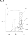
- a freezer/refrigerator includes a refrigerant circuit including the above refrigerant compressor, a heat radiator, a decompressor, and a heat absorber, the refrigerant circuit being configured such that the refrigerant compressor, the heat radiator, the decompressor, and the heat absorber are annularly coupled to one another by pipes.
- the present invention can achieve the effect of being able to provide the refrigerant compressor capable of realizing satisfactory reliability at the sliding portion even when lubricating oil having low viscosity is used, and a freezer/refrigerator including the refrigerant compressor.
- a refrigerant compressor which reserves lubricating oil having kinetic viscosity of 0.1 to 5.1 mm 2 /S at 40 C in a sealed container, and accommodates therein an electric component, and a compression component which is driven by the electric component and compresses a refrigerant.
- the compression component includes: as a shaft portion, a crank shaft including a main shaft and an eccentric shaft; and as a bearing portion supporting the shaft portion, a main bearing supporting the main shaft and an eccentric bearing supporting the eccentric shaft.
- a treated surface having hardness equal to or more than hardness of the bearing portion is formed on at least one of a surface of the main shaft and a surface of the eccentric shaft.
- the high-hardness treated surface is formed on the surface of the main shaft or the surface of the eccentric shaft, or the high-hardness treated surfaces are formed on both the surface of the main shaft and the surface of the eccentric shaft. Therefore, even when the viscosity of the lubricating oil is low, the shaft portion and the bearing portion can be satisfactorily lubricated. With this, the abrasion of the sliding surface of the shaft portion can be satisfactorily suppressed, and therefore, the reliability of the refrigerant compressor can be made further satisfactory.
- the above refrigerant compressor may be configured such that: a base material of the shaft portion is an iron-based material; and the treated surface is an oxide film.
- the treated surface is the iron-based oxide film
- the hardness of the surface of the shaft portion (the main shaft and/or the eccentric shaft) can be made high, and in addition, the effect of, for example, being able to hold the low-viscosity lubricating oil can also be obtained.
- the abrasion of the sliding surface of the shaft portion can be satisfactorily suppressed, and therefore, the reliability of the refrigerant compressor can be made further satisfactory.
- the above refrigerant compressor may be configured such that the oxide film includes, on an outermost surface thereof, at least one of a portion containing diiron trioxide (Fe 2 O 3 ) and a portion constituted by at least fine crystals.
- the oxide film includes, on an outermost surface thereof, at least one of a portion containing diiron trioxide (Fe 2 O 3 ) and a portion constituted by at least fine crystals.
- the hardness of the outermost surface of the oxide film becomes high.
- the abrasion of the sliding surface of the shaft portion (the main shaft and/or the eccentric shaft) can be satisfactorily suppressed, and therefore, the reliability of the refrigerant compressor can be made further satisfactory.
- the above refrigerant compressor may be configured such that a ratio L/D of a length L of the bearing portion to an inner diameter D of the bearing portion falls within a range of 0.10 to 1.20.
- the abrasion of the sliding surface of the shaft portion can be satisfactorily suppressed. Therefore, the reliability of the refrigerant compressor can be made further satisfactory.
- the above refrigerant compressor may be configured such that the lubricating oil is at least one selected from the group consisting of mineral oil, alkyl benzene oil, and ester oil.
- the above refrigerant compressor may be configured such that the lubricating oil is the mineral oil or the alkyl benzene oil and contains an extreme pressure additive at 0.5 to 8.0 wt.%.
- the lubricating oil may be the ester oil and contain an extreme pressure additive at 2.0 to 4.0 wt.%.
- the extreme pressure additive may be a phosphorus compound.
- the effect by the addition of the extreme pressure additive can be satisfactorily exhibited regardless of the type of the lubricating oil.
- the abrasion of the sliding surface of the shaft portion (the main shaft and/or the eccentric shaft) can be satisfactorily suppressed, and therefore, the reliability of the refrigerant compressor can be made further satisfactory.
- the above refrigerant compressor may be configured such that the lubricating oil contains an oily agent.
- the abrasion of the sliding surface of the shaft portion (the main shaft and/or the eccentric shaft) can be satisfactorily suppressed by the addition of the oily agent, and therefore, the reliability of the refrigerant compressor can be made further satisfactory.
- the above refrigerant compressor may be configured such that the electric component is inverter-driven at a plurality of operation frequencies.
- the present disclosure includes a freezer/refrigerator including a refrigerant circuit including the above refrigerant compressor, a heat radiator, a decompressor, and a heat absorber, the refrigerant circuit being configured such that the refrigerant compressor, the heat radiator, the decompressor, and the heat absorber are annularly coupled to one another by pipes.
- Fig. 1A is a sectional view of a refrigerant compressor 100 according to Embodiment 1 of the present disclosure.
- a sealed container 101 of the refrigerant compressor 100 is filled with, for example, R600a as refrigerant gas, and mineral oil as lubricating oil 103 is stored in a bottom portion of the sealed container 101.
- the viscosity of the lubricating oil 103 used in the present disclosure is low, i.e., falls within a range of VG0 to VG5 (i.e., grades in which kinetic viscosity at 40°C falls within a range of 0.1 to 5.1 mm 2 /S).
- the lubricating oil 103 is low-viscosity mineral oil.
- the lubricating oil 103 is not limited to this. Further, as described below, the lubricating oil 103 may contain an extreme pressure additive and/or an oily agent.
- the electric component 106 and a compression component 107 are accommodated in the sealed container 101.
- the electric component 106 is constituted by a stator 104 and a rotor 105.
- the compression component 107 is a reciprocating type driven by the electric component 106 and includes a crank shaft 108, a cylinder block 112, a piston 120, and the like.
- the crank shaft 108 is constituted by a main shaft 109 and an eccentric shaft 110.
- the main shaft 109 is press-fitted and fixed to the rotor 105.
- the eccentric shaft 110 is formed eccentrically with respect to the main shaft 109.
- An oil supply pump (not shown) is provided at a lower end of the crank shaft 108.
- the cylinder block 112 is constituted by, for example, cast iron.
- the cylinder block 112 forms a substantially cylindrical bore 113 and includes a main bearing 114 supporting the main shaft 109 of the crank shaft 108.
- the piston 120 is inserted in the bore 113 so as to be able to reciprocate, and with this, a compression chamber 121 is formed.
- a piston pin 115 has, for example, a substantially cylindrical shape and is arranged parallel to the eccentric shaft 110. The piston pin 115 is locked to a piston pin hole of the piston 120 so as not to be rotatable.
- a coupler (coupling means) 117 is constituted by, for example, an aluminum casting and includes an eccentric bearing 119 supporting the eccentric shaft 110.
- the coupler 117 couples the eccentric shaft 110 and the piston 120 through the piston pin 115.
- An end surface of the bore 113 is sealed by a valve plate 122.
- the main shaft 109 and eccentric shaft 110 included in the crank shaft 108 are collectively called a "shaft portion.”
- the main bearing 114 supporting the main shaft 109 and the eccentric bearing 119 supporting the eccentric shaft 110 are collectively called a "bearing portion.”
- a cylinder head 123 forms a high pressure chamber (not shown) and is fixed to the valve plate 122 at an opposite side of the bore 113.
- a suction tube (not shown) is fixed to the sealed container 101 and connected to a low-pressure side (not shown) of a refrigeration cycle. The suction tube introduces the refrigerant gas into the sealed container 101.
- a suction muffler 124 is sandwiched between the valve plate 122 and the cylinder head 123.
- Respective sliding portions of the refrigerant compressor 100 are formed by: the main shaft 109 of the crank shaft 108 and the main bearing 114; the piston 120 and the bore 113; the piston pin 115 and a connecting rod of the coupler 117; the eccentric shaft 110 of the crank shaft 108 and the eccentric bearing 119 of the coupler 117; and the like.
- the refrigerant compressor 100 configured as above, first, electric power supplied from a commercial power supply (not shown) is supplied to the electric component 106 to rotate the rotor 105 of the electric component 106.
- the rotor 105 rotates the crank shaft 108, and an eccentric motion of the eccentric shaft 110 drives the piston 120 through the coupler 117 and the piston pin 115.
- the piston 120 reciprocates in the bore 113, and with this, the refrigerant gas introduced into the sealed container 101 through the suction tube is sucked from the suction muffler 124 and compressed in the compression chamber 121.
- a specific method of driving the refrigerant compressor 100 is not especially limited.
- the refrigerant compressor 100 may be driven by simple on-off control but may be inverter-driven at a plurality of operation frequencies.
- the inverter drive in order to optimize operation control of the refrigerant compressor 100, a low-speed operation in which the amount of oil supplied to each sliding portion becomes small or a high-speed operation in which the rotational frequency of the electric component 106 increases occurs.
- the abrasion of the main shaft 109 can be satisfactorily suppressed, and therefore, the reliability of the refrigerant compressor 100 can be improved.
- the main shaft 109 of the crank shaft 108 is rotatably fitted to the main bearing 114 to constitute the sliding portion. Therefore, for convenience of explanation, the sliding portion constituted by the main shaft 109 and the main bearing 114 is referred to as a "main shaft sliding portion.”
- the eccentric shaft 110 of the crank shaft 108 is rotatably fitted to the eccentric bearing 119 to constitute the sliding portion. Therefore, for convenience of explanation, the sliding portion constituted by the eccentric shaft 110 and the eccentric bearing 119 is referred to as an "eccentric shaft sliding portion.” Further, the "main shaft sliding portion” and the “eccentric shaft sliding portion” are collectively called a "shaft portion sliding portion.”
- the lubricating oil 103 is supplied from the oil supply pump to the respective sliding portions.
- the sliding portions are lubricated.
- the lubricating oil 103 serves as a seal between the piston 120 and the bore 113.
- Fig. 1B is an enlarged view showing the main shaft 109 and the main bearing 114 which are surrounded by a broken line circle in the refrigerant compressor 100 shown in Fig. 1A and shows a length L of the main bearing 114 and an inner diameter D of the main bearing 114.
- Fig. 1B is an enlarged view of the main shaft sliding portion of the shaft portion sliding portion.
- the contact state between the main shaft 109 and the main bearing 114 is a metallic contact state.
- the rotational motion starts from the metallic contact state. Therefore, large frictional resistance force acts on the main shaft sliding portion.
- a treated surface (surface treatment) having hardness equal to or more than hardness of the main bearing 114 is formed on the surface of the main shaft 109.
- Embodiment 1 a treated surface having hardness equal to or more than hardness of the eccentric bearing 119 is formed on the surface of the eccentric shaft 110.
- the treated surface of the shaft portion is formed on each of the surface of the main shaft 109 and the surface of the eccentric shaft 110.
- the treated surface may be formed only on the surface of the main shaft 109 or the surface of the eccentric shaft 110.
- the treated surface formed on the surface of the shaft portion is not especially limited as long as the treated surface has hardness at least equal to hardness of the bearing portion (the main bearing 114 and/or the eccentric bearing 119) or hardness equal to or more than hardness of the bearing portion.
- a preferable example of the treated surface in Embodiment 1 is a below-described oxide film.
- gray cast iron (FC cast iron) is used as a base material, and a treated surface (below-described oxide film, for example) is formed on the surface of the base material.
- the base material of the crank shaft 108 is not limited to gray cast iron and may be a known iron-based material. Typical examples of the base material include general cast irons, such as gray cast iron. However, the base material is not limited to these.
- the base material may be a steel material, a sintered material, or other iron-based material.
- the type of the cast iron is not especially limited, and the cast iron may be gray cast iron (plain cast iron, FC cast iron) as described above or may be spheroidal graphite cast iron (FCD cast iron) or other cast iron.
- a ratio L/D of the length L of the main bearing 114 to the inner diameter D of the main bearing 114 fall within a range of 0.10 to 1.20.
- the same is true for the eccentric shaft sliding portion.
- the treated surface such as the below-described oxide film, having the hardness equal to or more than the hardness of the bearing portion is used at the shaft portion sliding portion of the refrigerant compressor 100.
- the ratio L/D falls within the above range, and the viscosity of the lubricating oil 103 is low, the satisfactory lubricating effect can be realized. Therefore, the reliability of the shaft portion sliding portion can be further improved.
- the upper limit of the ratio L/D is only required to be 1.20 or less. However, the upper limit of the ratio L/D can be set to 0.45 or less. Therefore, one example of the more preferable range of the ratio L/D is a range of 0.10 to 0.45.
- a nano indentation apparatus (triboindenter) produced by Scienta Omicron, Inc. can be used.
- triboindenter As a specific method of measuring the hardness, performed 15 times is a step in which: an indenter is pressed against the surface to apply a load to the surface for a certain period of time; the application of the load is slightly reduced; and the indenter is again pressed against the surface to apply a load higher than the previous load. Such loading-unloading test is repeated such that the highest load becomes 1 N. With this, the hardness of the measurement target and the hardness of the measurement target in the depth direction can be measured.
- the measurement of Vickers hardness of the bearing portion of the shaft portion sliding portion will be explained.
- a part of an inner peripheral surface of the main bearing 114 of the cylinder block 112 or a part of an inner peripheral surface of the eccentric bearing 119 of the coupler 117 is cut by a fine cutter as a measurement sample. Then, the Vickers hardness of the measurement sample is only required to be measured under a condition of a load of 0.5 kgf.
- the treated surface of the shaft portion (at least one of the main shaft 109 and the eccentric shaft 110 in the crank shaft 108) has the hardness equal to or more than the hardness of the bearing portion (at least one of the main bearing 114 and the eccentric bearing 119) that is an opponent sliding member.
- the hardness in the present disclosure is one of mechanical properties of especially the surface of a substance or material or the vicinity of the surface of the substance or material.
- the hardness can be defined as the unlikelihood of the deformation of an object and the unlikelihood of the damage of the object when the material is deformed or damaged by a foreign matter.
- Regarding the hardness there are various measurement means (definitions) and their corresponding values (measures of the hardness).
- the sliding members are made of a metal or a nonferrous metal
- whether or not the film on the surface of the sliding member is harder than the opponent sliding member can be determined by using the same indentation hardness test method (such as the above-described nano indentation method, the Vickers hardness method, or the Rockwell hardness method).
- a ring-on-disk abrasion test can be used.
- One example of such evaluation method is a method of observing the state of the sliding surface by: forming a film on the surface of a disk; and rotating the disk at a rotational speed of 1 m/s for about an hour while applying a load of 1000 N to the film with the disk immersed in oil. As a result, it may be determined that the ring or the disk including the film which is larger in abrasion loss has lower hardness.
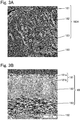
- Fig. 2A is a SEM (scanning electron microscope) image showing a configuration example of a typical oxide film 160.
- Fig. 2B is a TEM (transmission electron microscope) image showing the configuration of another typical oxide film 170A.
- Fig. 2C is a TEM (transmission electron microscope) image showing the configuration of yet another typical oxide film 170B.
- Fig. 3A is a TEM (transmission electron microscope) image showing a typical configuration of still another typical oxide film 180A.
- Fig. 3B is a SIM (scanning ion microscope) image showing the configuration of yet another typical oxide film 180B.
- the base material of the oxide film as the typical example of the high-hardness treated surface formed on the surface of the shaft portion is an iron-based material, and the oxide film is only required to be formed by oxidizing the surface of the iron-based material.
- One preferable example of the oxide film is configured such that the oxide film includes, on an outermost surface thereof, at least one of a portion containing diiron trioxide (Fe 2 O 3 ) and a portion constituted by at least fine crystals.
- the oxide film having such preferable configuration include the oxide films 160, 170A, 170B, 180A, and 180B shown in Figs. 2A to 3B .
- the oxide film 160 shown in Fig. 2A includes the portion containing diiron trioxide (Fe 2 O 3 ) at the outermost surface side. Further, the oxide film 160 includes a silicon-containing portion at a base material 150 side, the silicon-containing portion containing a larger amount of silicon (Si) than the base material 150.
- Si silicon
- the oxide film 160 may include a spot-shaped silicon-containing portion which is located closer to the surface of the oxide film 160 than the silicon-containing portion and is partially larger in silicon (Si) content than its surroundings.
- the oxide film 160 may be constituted by at least a portion in which a component contained most is diiron trioxide (Fe 2 O 3 ) and a portion in which a component contained most is triiron tetroxide (Fe 3 O 4 ), which portions are arranged in this order from the outermost surface.
- the oxide film 160 may be constituted by at least a portion in which a component contained most is diiron trioxide (Fe 2 O 3 ), a portion in which a component contained most is triiron tetroxide (Fe 3 O 4 ), and a portion in which a component contained most is iron oxide (FeO), which portions are arranged in this order from the outermost surface.
- a component contained most is diiron trioxide (Fe 2 O 3 )
- a portion in which a component contained most is triiron tetroxide (Fe 3 O 4 )
- FeO iron oxide
- the oxide film 160 will be specifically explained with reference to Fig. 2A .
- the oxide film 160 is formed on the base material 150 (in Fig. 2A , at the right side of the base material 150) made of spheroidal graphite cast iron (FCD cast iron).
- FCD cast iron spheroidal graphite cast iron
- the oxide film 160 was analyzed by energy-dispersive X-ray spectroscopy (EDS). Although specific results are not shown, an iron (Fe) intensity ratio of the oxide film 160 is smaller than that of the base material 150, and the iron (Fe) intensity ratio tends to increase slightly inside the oxide film 160. Further, an oxygen (O) intensity ratio of the oxide film 160 is significantly larger than that of the base material 150. A silicon (Si) intensity ratio of a portion of the oxide film 160 which portion is located close to the base material 150 is larger than that of the base material 150. The silicon (Si) intensity ratio significantly decreases inside the oxide film 160, and the silicon (Si) intensity ratio of a portion of the oxide film 160 which portion is located close to the outermost surface is almost a detection limit or less.
- EDS energy-dispersive X-ray spectroscopy
- an oxide of iron and silicon such as fayalite (Fe 2 SiO 4 ) is formed in the vicinity of an interface at the base material 150. It is thought that: the oxide exhibits a so-called iron diffusion barrier function; and as the oxidation reaction proceeds, the oxide creates a state of lack of iron on the surface of the base material 150. With this, it is thought that internal diffusion of oxygen is promoted by the progress of the oxidation reaction.
- the oxide film 160 shown in Fig. 2A is only required to be constituted by at least a portion in which a component contained most is diiron trioxide (Fe 2 O 3 ) (for convenience sake, this portion is referred to as a "III portion” based on diiron trioxide (Fe 2 O 3 ), i.e., based on "iron(III) oxide.") and a portion in which a component contained most is triiron tetroxide (Fe 3 O 4 ) (for convenience sake, this portion is referred to as a "II-III portion” based on triiron tetroxide (Fe 3 O 4 ), i.e., based on "iron(II) iron(III) oxide.”), which portions are arranged in this order from the outermost surface (sliding surface) (Film Configuration 1).
- the oxide film 160 shown in Fig. 2A may be constituted by at least the III portion in which a component contained most is diiron trioxide (Fe 2 O 3 ), the II-III portion in which a component contained most is triiron tetroxide (Fe 3 O 4 ), and a portion in which a component contained most is iron oxide (FeO) (for convenience sake, this portion is referred to as a "II portion” based on iron oxide (FeO), i.e., based on "iron(II) oxide.”), which portions are arranged in this order from the outermost surface (sliding surface) (Film Configuration 2).
- the major component of the III portion on the outermost surface is diiron trioxide (Fe 2 O 3 ), and the II-III portion in which the major component is triiron tetroxide (Fe 3 O 4 ) is located under the III portion. Since triiron tetroxide (Fe 3 O 4 ) is a cubic crystal stronger than diiron trioxide (Fe 2 O 3 ) in terms of the crystal structure, the III portion is supported by the II-III portion as a lower layer.
- the II portion in which the major component is iron oxide (FeO) is located under the II-III portion. Since iron oxide (FeO) exists at the interface on the surface of the base material 150 in an amorphous state not including the crystal structure, the existence of weak structures, such as a crystal grain boundary and a lattice defect, can be adequately suppressed. Therefore, the proof stress of the oxide film 160 with respect to the load applied when the sliding member slides improves. As a result, this may contribute to the suppression of the separation of the oxide film 160 and the improvement of the adhesive force of the oxide film 160 with respect to the base material 150.
- the II-III portion can be divided into a portion which is located close to the surface and small in silicon (Si) content and a portion which is located close to the base material 150 and small in silicon (Si) content.
- the upper portion which is small in silicon (Si) content is referred to as a "II-III-a portion”
- the lower portion which is large in silicon (Si) content is referred to as a "II-III-b portion.”
- the interface between the II-III-a portion and the II-III-b portion coincides with a portion where the silicon (Si) intensity ratio significantly decreases inside the oxide film 160 according to the above-described EDS analysis.
- the portion(s) (the II-III portion, or the II-III portion and the II portion) of the oxide film 160 which portion(s) is located close to the base material 150 is a silicon-containing portion(s) larger in silicon (Si) content than the base material 150.
- the portion (at least one of the II-III portion and the III portion) located closer to the surface than the silicon-containing portion contains a spot-shaped silicon-containing portion which is partially larger in silicon (Si) content than its peripheral composition.
- the spot-shaped silicon-containing portion is observed as a while spot with, for example, a TEM (transmission electron microscope), the spot-shaped silicon-containing portion may be referred to as a "white portion.” In this "white portion,” an increase in silicon (Si) concentration or strength is observed.
- the upper II-III-a portion is lower in silicon (Si) content than the lower II-III-b portion (silicon-containing portion).
- the "white portion,” i.e., the spot-shaped silicon-containing portion is contained inside the II-III-a portion.
- the III portion located close to the outermost surface hardly contains silicon (Si), but the "white portion,” i.e., the spot-shaped silicon-containing portion can be made to exist in the III portion by adjusting conditions.
- the spot-shaped silicon-containing portion there exist silicon (Si) compounds, such as silicon dioxide (SiO 2 ) and/or fayalite (Fe 2 SiO 4 ), which are different in structure from each other. Further, in the "white portion,” there may exist silicon (Si) in a solid solution state (exist silicon (Si) as a simple substance) instead of the silicon (Si) compound. Therefore, in the III portion and/or the II-III-a portion, there may exist, as the spot-shaped silicon-containing portion, not only the portion containing the silicon (Si) compound but also the silicon (Si) solid solution portion.
- the oxide film 160 is only required to include at least the lamellar silicon-containing portion (a part of the II-III portion, the II portion, etc.) located close to the base material 150.
- the oxide film 160 is only required to include the spot-shaped silicon-containing portion which is located at a position closer to the surface than the silicon-containing portion and is larger in silicon (Si) content than its surroundings.
- examples of the specific configuration of the oxide film 160 include Film Configuration 1 including the III portion and the II-III portion and Film Configuration 2 including the III portion, the II-III portion, and the II portion.
- the configuration of the oxide film 160 is not limited to these.
- the oxide film 160 is formed such that the III portion, the II-III-a portion, and the II-III-b portion (and the II portion) are laminated in this order from the outermost surface.
- the configuration of the oxide film 160 is not limited to the three-layer configuration and the four-layer configuration.
- the oxide film 160 may contain other layer(s), or one or more of the layers of the oxide film 160 may be omitted or replaced.
- the configuration including other layer(s), the configuration from which one or more layers are omitted, and the configuration in which the order of the layers laminated is made different can be easily realized by adjusting the below-described conditions.
- Each of the oxide films 170A and 170B includes: a composition-A portion in which a component contained most is diiron trioxide (Fe 2 O 3 ); a composition-B portion in which a component contained most is triiron tetroxide (Fe 3 O 4 ) and which contains a silicon (Si) compound; and a composition-C portion in which a component contained most is triiron tetroxide (Fe 3 O 4 ) and which is larger in silicon content than the composition-B portion.
- the oxide film 170A may be constituted by at least an outermost portion 171 as the composition-A portion, an intermediate portion 172 as the composition-B portion, and an inner portion 173 as the composition-C portion, which portions are arranged in this order from the outermost surface
- the oxide film 170B may be constituted by at least an outermost portion 175 as the composition-A portion, an intermediate portion 176 as the composition-B portion, and an inner portion 177 as the composition-C portion, which portions are arranged in this order from the outermost surface.
- the silicon (Si) compound may also be contained in the composition-A portion.
- the silicon (Si) compound is not especially limited and may be at least one of silicon dioxide (SiO 2 ) and fayalite (Fe 2 SiO 4 ).
- the oxide film 170A shown in Fig. 2B will be specifically explained.
- the oxide film 170A is formed on the base material 150 (in Fig. 2B , at the right side of the base material 150) that is, for example, gray cast iron (FC cast iron).
- FC cast iron gray cast iron
- the oxide film 170A has a three-portion structure (three-layer structure) in which the outermost portion 171 (first layer), the intermediate portion 172 (second layer), and the inner portion 173 (third layer) are arranged in this order from the outermost surface.
- white portions 174 partially exist in the intermediate portion 172 that is the second layer.
- the oxide film 170A was by the EDS in the same manner as the above analysis of the oxide film 160. Although specific results are not shown, elements of iron (Fe) and oxygen (O) exist entirely from the outermost portion 171 to the inner portion 173 in the oxide film 170A. However, silicon (Si) hardly exists in the outermost portion 171, or the amount of silicon (Si) in the outermost portion 171 is small. Further, silicon (Si) exists in a part of the intermediate portion 172 and a most part of the inner portion 173.
- the white portion 174 included in the intermediate portion 172 there exists oxygen (O) which does not combine with iron (Fe) but combines with silicon (Si) and also exists oxygen (O) which combines with both iron (Fe) and silicon (Si). Therefore, in the white portion 174, there exist plural types of silicon (Si) compounds, such as silicon dioxide (SiO 2 ) and fayalite (Fe 2 SiO 4 ), which are different in structure from one another.
- the oxide film 170B shown in Fig. 2C will be specifically explained. As shown in Fig. 2C , it is clearly confirmed that the oxide film 170B is formed on the base material 150 (not shown), and as with the oxide film 170A, the oxide film 170B has a three-portion structure (three-layer structure) in which the outermost portion 175 (first layer), the intermediate portion 176 (second layer), and the inner portion 177 (third layer) are arranged in this order from the outermost surface.
- the outermost portion 175 is the composition-A portion, and a component contained most in the outermost portion 175 is diiron trioxide (Fe 2 O 3 ).
- the intermediate portion 176 is the composition-B portion.
- a component contained most in the intermediate portion 176 is triiron tetroxide (Fe 3 O 4 ), and the intermediate portion 176 also contains the silicon (Si) compound.
- the inner portion 177 is the composition-C portion.
- a component contained most in the inner portion 177 is triiron tetroxide (Fe 3 O 4 ), and the inner portion 177 is larger in silicon content than the composition-B portion.
- silicon (Si) of the oxide film 170B was analyzed by the EDS. Although specific results are not shown, the concentration of silicon (Si) is high in the base material 150, and the concentration of silicon (Si) is high also in the inner portion 177 of the oxide film 170B, the inner portion 177 being located close to the base material 150. On the other hand, the concentration of silicon (Si) significantly decreases at the interface between the inner portion 177 and the intermediate portion 176.
- the white portion 174 exists in the intermediate portion 176 as with the intermediate portion 172 of the oxide film 170A. According to the analysis by the EDS, an increase in silicon (Si) concentration is observed at a portion corresponding to the white portion 174. Further, although silicon (Si) is hardly confirmed in the outermost portion 171 of the oxide film 170A, the white portion 174 is confirmed in the outermost portion 175 of the oxide film 170B, and an increase in silicon (Si) concentration is observed at a portion corresponding to the white portion 174. Further, the existence of silicon (Si) in the oxide film 170B was analyzed by electron-ray energy loss spectroscopy (EESL). It is confirmed that although not shown, silicon (Si) which combines with oxygen (O) exists at any portion in the oxide film 170B.
- EESL electron-ray energy loss spectroscopy
- the oxide film 170B shown in Fig. 2C is basically the same in configuration as the oxide film 170A shown in Fig. 2B .
- the oxide film 170B is different from the oxide film 170A in that the silicon (Si) compounds, such as silicon dioxide (SiO 2 ), exist not only in the inner portion 177 and the intermediate portion 176 but also in the outermost portion 175.
- Si silicon
- SiO 2 silicon dioxide
- the oxide film 170A shown in Fig. 2B is constituted by at least the outermost portion 171 as the composition-A portion, the intermediate portion 172 as the composition-B portion, and the inner portion 173 as the composition-C portion, which portions are arranged in this order from the outermost surface
- the oxide film 170B shown in Fig. 2C is constituted by at least the outermost portion 175 as the composition-A portion, the intermediate portion 176 as the composition-B portion, and the inner portion 177 as the composition-C portion, which portions are arranged in this order from the outermost surface.
- each of the configurations of the oxide films 170A and 170B is not limited to the three-layer structure.
- each of the oxide films 170A and 170B is only required to include the composition-A portion, the composition-B portion, and the composition-C portion. Therefore, needless to say, each of the oxide films 170A and 170B may contain a composition portion(s) other than the above portions.
- Each of the configurations of the oxide films 170A and 170B is not limited to the configuration in which the composition-A portion, the composition-B portion, and the composition-C portion are laminated in this order from the outermost surface.
- One example of each of the configurations of the oxide films 170A and 170B is a configuration in which the composition-B portion, the composition-A portion, and the composition-C portion are laminated in this order from the outermost surface.
- the configuration including other portion(s) and the configuration in which the order of the portions laminated is made different can be easily realized by adjusting below-described conditions.
- Each of the oxide films 180A and 180B includes: a first portion 181 constituted by at least fine crystals; a second portion 182 containing columnar structures; and/or a third portion 183 containing lamellar structures.
- each of the oxide films 180A and 180B is constituted by at least the first portion 181 located on the outermost surface, the second portion 182 located under the first portion 181, and the third portion 183 located under the second portion 182.
- a crystal grain diameter of the first portion 181 may be smaller than that of the second portion 182.
- the crystal grain diameter of the fine crystal constituting the first portion 181 is not especially limited but may fall within a range of 0.001 to 1 ⁇ m.
- the first portion 181 is constituted by substantially a single portion.
- the configuration of the first portion 181 is not limited to this.
- the first portion 181 may be constituted by at least a first-a portion 181a and a first-b portion 181b which are different in crystal density from each other. Specific configurations of the first-a portion 181a and the first-b portion 181b are not especially limited.
- the first portion 181 may be configured such that: the first-a portion 181a is located at the surface side; the first-b portion 181b is located under the first-a portion 181a; and the crystal density of the first-a portion 181a is lower than the crystal density of the first-b portion 181b.
- first portion 181, the second portion 182, and the third portion 183 are not especially limited.
- first portion 181 includes the first-a portion 181a
- the first-a portion 181a may contain vertically long needle structures each of whose aspect ratio falls within a range of 1 to 1000.
- the second portion 182 may contain vertically long crystal structures each of whose aspect ratio falls within a range of 1 to 20.
- the third portion 183 may contain laterally long crystal structures each of whose aspect ratio falls within a range of 0.01 to 1.
- the oxide film 180A shown in Fig. 3A will be specifically explained.
- the oxide film 180A is constituted by at least the first portion 181, the second portion 182, and the third portion 183, which are arranged in this order from the outermost surface.
- the first portion 181 is made of fine crystals.
- the second portion 182 is located under the first portion 181 and contains vertically long columnar structures.
- the third portion 183 is located under the second portion 182 and contains laterally long lamellar structures.
- the base material 150 is located under the third portion 183.
- the third portion 183 is located under the second portion 182.
- the third portion 183 is constituted by structures each having a vertical diameter of several tens of nanometers or less and a lateral diameter of about several hundreds of nanometers.
- An aspect ratio obtained by dividing the vertical diameter of the structure by the lateral diameter of the structure falls within a range of 0.01 to 0.1, and therefore, the structure is laterally long. Therefore, it is understood that the "laterally long" lamellar structures each having a low aspect ratio are formed in the third portion 183.
- the third portion 183 cementite that is the structure of the base material 150 is confirmed. On the other hand, cementite is not confirmed in the first portion 181 and the second portion 182. Therefore, it is thought that the third portion 183 is formed such that oxygen is diffused in the base material 150 by the oxidation treatment of the base material 150. On the other hand, it is thought that the first portion 181 and the second portion 182 are formed such that oxides grow on the surface of the base material 150.
- the oxide film 180A (and the oxide film 180B shown in Fig. 3B ) is only required to be constituted by the first portion 181 and at least one of the second portion 182 and the third portion 183.
- each of the oxide films 180A and 180B can be constituted by two layers that are the first portion 181 and the second portion 182 or two layers that are the first portion 181 and the third portion 183.
- the oxide film 180A (and the oxide film 180B) is constituted by three layers that are the first portion 181, the second portion 182, and the third portion 183 as described above.
- one example of the typical configuration of the oxide film 180A is the three-layer structure in which the first portion 181, the second portion 182, and the third portion 183 are arranged in this order from the outermost surface.
- the oxide film 180A may contain other portion(s), and the order of the portions laminated can be suitably set by adjusting conditions.
- the first portion 181 is constituted by the structures of fine crystals. This does not mean that the first portion 181 does not contain structures other than the fine crystals.
- the first portion 181 is substantially constituted by the fine crystals but may contain, for example, other structures as "impurities.” Therefore, the first portion 181 is only required to be constituted by at least the fine crystals, in other words, is only required to contain the fine crystals as major structures, and may contain other structures.
- the second portion 182 is only required to contain the columnar structures.
- the second portion 182 may contain other structures or may be substantially constituted by the columnar structures.
- the third portion 183 is only required to contain the lamellar structures.
- the third portion 183 may contain other structures or may be substantially constituted by the lamellar structures.
- the first portion 181, the second portion 182, and the third portion 183 are formed as the oxide film 180A (or the oxide film 180B) on the surface of the base material 150, and with this, are only required to be able to exhibit the hardness equal to or more than the hardness of the bearing portion. Therefore, needless to say, the first portion 181, the second portion 182, and the third portion 183 may contain structures other than the structures essential for these portions.
- the first portion 181 is only required to contain the structures formed by spreading nano-level fine crystals, and the upper limit of the grain diameter of the fine crystal is not limited to 100 nm or less.
- the grain diameter of the fine crystal is only required to fall within a range of 0.001 ⁇ m (1 nm) to 1 ⁇ m (1000 nm).
- the second portion 182 is only required to be configured such that the innumerable "vertically long" columnar structures each having a high aspect ratio are formed in the same direction.
- the aspect ratio of the columnar structure is not limited to a range of 3 to 10.
- the aspect ratio of the columnar structure is only required to fall within a range of 1 to 20.
- the third portion 183 is only required to be configured such that the "laterally long" lamellar structures each having a low aspect ratio are formed.
- the aspect ratio of the lamellar structure is not limited to a range of 0.01 to 0.1.
- the aspect ratio of the lamellar structure is only required to fall within a range of 0.01 to 1.
- Each of the grain diameter of the fine crystal of the first portion 181, the aspect ratio of the columnar structure of the second portion 182, and the aspect ratio of the lamellar structure of the third portion 183 can be set to a preferred range by suitably setting below-described conditions.
- the oxide film 180B shown in Fig. 3B will be specifically explained.
- the oxide film 180B is constituted by at least the first portion 181, the second portion 182, and the third portion 183, which are arranged in this order from the outermost surface.
- the first portion 181 is made of fine crystals.
- the second portion 182 is located under the first portion 181 and contains vertically long columnar structures.
- the third portion 183 is located under the second portion 182 and contains laterally long lamellar structures.
- the base material 150 is located under the third portion 183.
- the first portion 181 of the oxide film 180B can be divided into the first-a portion 181a and the first-b portion 181b which are different in crystal density from each other.
- the first portion 181 formed on the outermost surface of the oxide film 180B is constituted by the structures formed by spreading the fine crystals each having a grain diameter of 100 nm or less. Since the first portion 181 of the oxide film 180B is substantially constituted by the fine crystals, the first portion 181 of the oxide film 180B can be regarded as a "single layer" as with the first portion 181 of the oxide film 180A. However, from the viewpoint of the density of the fine crystals, the first portion 181 of the oxide film 180B can be divided into the first-a portion 181a located close to the outermost surface and the first-b portion 181b located close to the base material 150 (second portion 182). The first-a portion 181a is lower in crystal density than the first-b portion 181b located under the first-a portion 181a.
- the first-a portion 181a is constituted by at least the fine crystals and includes void portions (black portions in Fig. 3B ) in some places.
- the first-a portion 181a contains vertically long needle structures each having a minor-axis length of 100 nm or less and an aspect ratio within a range of 1 to 10.
- the first-b portion 181b located under the first-a portion 181a does not contain so much void portions and needle structures.
- the first-b portion 181b contains the structures formed by spreading nano-level fine crystals.
- the second portion 182 is located under the first-b portion 181b.
- the second portion 182 is constituted by the structures each having a vertical diameter of about 500 nm to 1 ⁇ m and a lateral diameter of about 100 to 150 nm.
- An aspect ratio obtained by dividing the vertical diameter of the structure by the lateral diameter of the structure falls within a range of about 3 to 10, and therefore, the structure is vertically long.
- the second portion 182 is configured such that the innumerable "vertically long" columnar structures each having a high aspect ratio are formed in the same direction.
- the third portion 183 is located under the second portion 182.
- the third portion 183 is constituted by the structures each having a vertical diameter of several tens of nanometers or less and a lateral diameter of about several hundreds of nanometers.
- An aspect ratio obtained by diving the vertical diameter of the structure by the lateral diameter of the structure falls within a range of 0.01 to 0.1, and therefore, the structure is laterally long.
- the "laterally long" lamellar structures each having a low aspect ratio are formed in the third portion 183.
- the first portion 181 (the first-a portion 181a and the first-b portion 181b) is only required to contain the structures formed by spreading nano-level fine crystals, and the upper limit of the grain diameter of the fine crystal is not limited to 100 nm or less.
- the grain diameter of the fine crystal is only required to fall within a range of 0.001 ⁇ m (1 nm) to 1 ⁇ m (1000 nm).
- the percentage of the void portions in the first-a portion 181a be 10% or more. With this, the oil film can be easily formed on the sliding surface (an "oil holding property" of the sliding surface can be improved), and an opponent attacking property can be more satisfactorily suppressed. On the other hand, it is desirable that the percentage of the void portions in the first-b portion 181b be less than 10%. If the percentage of the void portions is too high, denseness (mechanical strength) of the structure may not be adequately improved, and therefore, the first-b portion 181b may not be able to satisfactorily support the first-a portion 181a, although it depends on comparison with the first-a portion 181a.
- a volume occupation percentage for example, 10%
- a boundary value or a threshold
- the first-a portion 181a contains not only the fine crystals but also the vertically long needle structures, and the aspect ratio of the needle structure is not especially limited.
- the needle structure of the oxide film 180B has a minor-axis length of 100 nm or less and an aspect ratio within a range of 1 to 10, but the aspect ratio may fall within a range of 1 to 1000.
- each of the oxide films 160 to 180B is not especially limited, but may fall within, for example, a range of 1 to 5 ⁇ m.
- a known iron-based material can be suitably used as the base material 150.
- the iron-based material that is the base material 150 may contain silicon within a range of 0.5 to 10% depending on the types of the oxide films 160 to 180B.
- Each of the configurations of the oxide films 160 to 180B used as the treated surfaces in the present disclosure is not limited to Configuration Example 1 (oxide film 160), Configuration Example 2 (oxide film 170A, 170B), and Configuration Example 3 (oxide film 180A, 180B). Needless to say, each of the configurations of the oxide films 160 to 180B may be other configuration. Further, as described above, in the oxide films 160 to 180B of the above configuration examples, variations of the specific configurations of the portions, the layers, and the like, variations of the order of the lamination, variations of the thickness, and the like can be realized by suitably adjusting conditions. The conditions are not especially limited, and a typical condition is a method of producing (forming) each of the oxide films 160 to 180B.
- a known method of oxidizing an iron-based material can be suitably used as the method of producing each of the oxide films 160 to 180B, but the method of producing each of the oxide films 160 to 180B is not especially limited. Production conditions and the like can be suitably set depending on conditions, such as the type of the iron-based material that is the base material 150, the surface state of the base material 150 (such as the above-described polishing finish), and required physical properties of the oxide films 160 to 180B.
- the gray cast iron as the base material 150 is oxidized by using known oxidizing gas, such as carbon dioxide gas, and a known oxidation facility at several hundreds of degrees Celsius (for example, 400 to 800°C). With this, each of the oxide films 160 to 180B can be formed on the surface of the base material 150.
- Examples of the other conditions include: a specific material as the base material 150 (such as cast iron, a steel material, or a sintered material as described above); components contained in the base material 150 (for example, the content of silicon (Si) in the cast iron or the content of carbon (C) or alloy component in other iron-based material); and the surface state of the base material 150 before the formation of each of the oxide films 160 to 180B (for example, a surface pretreatment).
- a specific material as the base material 150 such as cast iron, a steel material, or a sintered material as described above
- components contained in the base material 150 for example, the content of silicon (Si) in the cast iron or the content of carbon (C) or alloy component in other iron-based material
- the surface state of the base material 150 before the formation of each of the oxide films 160 to 180B for example, a surface pretreatment.
- the other conditions are not especially limited.
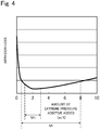
- Fig. 4 is a graph showing a relation between the amount of extreme pressure additive which can be added to the lubricating oil 103 and the abrasion loss of the main shaft sliding portion (the main shaft 109 and the main bearing 114) of the shaft portion sliding portion of the refrigerant compressor 100.
- the low-viscosity lubricating oil 103 having viscosity within a range of VG0 to VG5 is used, and (2) the treated surface having the hardness equal to or more than the hardness of the bearing portion is formed on the surface of the shaft portion (as a preferable example, one of the oxide films 160 to 180B is formed).
- the abrasion of the shaft portion sliding portion can be satisfactorily suppressed, and the reliability of the refrigerant compressor 100 can be made further satisfactory.
- the ratio L/D of the length L of the bearing portion to the inner diameter D of the bearing portion is set within a range of 0.10 to 1.20.
- a lubricating oil composition used as the lubricating oil 103 is adjusted (especially, the below-described extreme pressure additive and/or oily agent are added). With this, the abrasion of the shaft portion sliding portion can be further satisfactorily suppressed, and the reliability of the refrigerant compressor 100 can be made especially satisfactory.
- the lubricating oil composition used as the lubricating oil 103 is only required to contain as a major component an oily substance which satisfies the above item (1), i.e., which is low in viscosity within a range of VG0 to VG5.
- an oily substance which satisfies the above item (1), i.e., which is low in viscosity within a range of VG0 to VG5.
- an oily substance which satisfies the above item (1), i.e., which is low in viscosity within a range of VG0 to VG5.
- an oily substance which satisfies the above item (1), i.e., which is low in viscosity within a range of VG0 to VG5.
- at least one selected from the group consisting of mineral oil, alkyl benzene oil, and ester oil can be suitably used. These oily substances may be used alone or in combination of two types or more.
- the combination of two types or more of oily substances denotes not only, for example, a combination of two types or more of oily substances corresponding to the mineral oil but also, for example, a combination of one or more types of oily substances corresponding to the mineral oil and one or more types of oily substances corresponding to the alkyl benzene oil (or one or more types of oily substances corresponding to the ester oil).
- various additives may be added to the above one or more types of oily substances.
- Various additives known in the field of the lubricating oil 103 can be suitably used. Typical examples include an extreme pressure additive, an oily agent, an abrasion preventing agent, an oxidation inhibitor, an acid capturing agent, a metal inactivating agent, an antifoaming agent, a corrosion inhibitor, and a dispersing agent.
- an especially preferable one of these additives is the extreme pressure additive.
- the extreme pressure additive is added to the lubricating oil composition (one type of oily substance or two types or more of oily substances) for the purpose of reducing the abrasion of the surfaces (sliding surfaces) of a plurality of sliding members constituting the sliding portion and suppressing seizure of the sliding surfaces.
- the extreme pressure additive reacts with the sliding surface to form a film on the sliding surface, and with this, the reduction of the abrasion and the suppression of the seizure are realized.
- a known extreme pressure additive can be suitably used, and the extreme pressure additive is not especially limited.
- the extreme pressure additive include: phosphorus compounds such as phosphoric ester; sulfur compounds such as sulfurized fatty acid and its ester; and halogenated compounds such as chlorine-based hydrocarbon and fluorine-based hydrocarbon. These extreme pressure additives may be used alone or in combination of two types or more.
- the phosphorus compound can be preferably used.
- Typical examples of the phosphorus compound include tricresyl phosphate (TCP), tributyl phosphate (TBP), and triphenyl phosphate (TPP).
- TCP can be preferably used.
- the amount of extreme pressure additive added to the lubricating oil composition is not especially limited.
- the lubricating oil 103 is a low-polarity substance, such as mineral oil or alkyl benzene oil
- the amount of extreme pressure additive added to the lubricating oil composition is preferably within a range of 0.5 to 8.0 wt.% and more preferably within a range of 1 to 3 wt.%.
- the graph of Fig. 4 shows a relation between the amount of extreme pressure additive added and the abrasion loss of the main shaft sliding portion (shaft portion sliding portion) when the oily substance of the lubricating oil composition is the low-polarity substance, such as mineral oil. It should be noted that the abrasion loss of the main shaft sliding portion (shaft portion sliding portion) is evaluated by a known falex type friction tester.
- the abrasion loss of the main shaft sliding portion can be adequately reduced as compared to when the extreme pressure additive is not added (the amount added is 0 wt.%).
- the amount of extreme pressure additive added falls within a range of 0.5 wt.% or more and 8 wt.% or less, the abrasion loss can be significantly reduced, as shown in a range Mi in Fig. 4 .
- the amount of extreme pressure additive added is less than 0.5 wt.%, the effect of reducing the abrasion loss is inadequate as shown in Fig. 4 .
- the amount of extreme pressure additive added exceeds 8 wt.%, the abrasion loss reducing effect corresponding to the added amount cannot be obtained, and in addition, the abrasion loss tends to slightly increase by the increase in the added amount.
- the graph of Fig. 4 shows a curved line including a minimal value around the added amount of 2 wt.%. Therefore, it is thought that the especially satisfactory effect of reducing the abrasion loss can be obtained when the amount of extreme pressure additive added falls within a range of 2 wt.% ⁇ 1 wt.%, i.e., within a range of 1 wt.% or more and 3 wt.% or less, as shown by a range Mii in Fig. 4 .
- the extreme pressure additive when the lubricating oil 103 (oily substance) is the ester oil, the extreme pressure additive can be added within a range of 2.0 to 4.0 wt.%. Since the ester oil is an oily substance having a polarity, the ester oil is easily adsorbed by the iron-based material. Therefore, even when the extreme pressure additive is added to the lubricating oil composition (lubricating oil 103) containing the ester oil, the ester oil is adsorbed by the sliding surface before the extreme pressure additive is adsorbed. Thus, it is difficult for the extreme pressure additive to react with the sliding surface to form the film. On this account, typically, the extreme pressure additive is not added to the lubricating oil 103 (lubricating oil composition) containing the ester oil as a major component.
- the refrigerant compressor 100 satisfies at least the above items (1) and (2), and especially regarding the item (2), the oxide films 160 to 180B are suitably used.
- the oxide film any one of the oxide films 160 to 180B
- the effect of, for example, reducing the abrasion by the extreme pressure additive can be satisfactorily exhibited even when the low-viscosity lubricating oil 103 satisfying the item (1) is the lubricating oil composition containing the ester oil as the major component.
- the low-viscosity lubricating oil 103 is used, and the high-hardness treated surface (such as the oxide films 160 to 180B) is formed on the surface of the shaft portion constituting the shaft portion sliding portion.
- the high-hardness treated surface such as the oxide films 160 to 180B
- the ratio L/D of the length L of the bearing portion to the inner diameter D of the bearing portion can be made lower than before (above item (3)), so that the reliability of the refrigerant compressor 100 can be made further satisfactory.
- An oily agent may be added to the lubricating oil 103.
- the high-hardness treated surface such as the oxide films 160 to 180B, is formed on the sliding surface of the shaft portion sliding portion. Since a film can be formed on the sliding surface by the addition of the oily agent, the effect of reducing the abrasion by the oily agent can be made further satisfactory by the treated surface.
- a specific type of the oily agent is not especially limited, and examples of the oily agent include higher fatty acid, higher alcohol, ester, and metallic soap. These oily agents may be used alone or in combination of two types or more.
- the amount of oily agent added is not especially limited and may fall within, for example, a range of 0.01 to 1 wt.%. It is preferable that at least one type of extreme pressure additive be added to the lubricating oil 103 (lubricating oil composition). Further, at least one type of oily agent can be added. However, only the oily agent may be added without adding the extreme pressure additive. The same is true for the other additives.
- FIG. 5 schematically shows the configuration of the freezer/refrigerator including the refrigerant compressor 100 according to Embodiment 1. Therefore, in Embodiment 2, only the basic configuration of the freezer/refrigerator will be schematically explained.
- the freezer/refrigerator according to Embodiment 2 includes a main body 275, a partition wall 278, a refrigerant circuit 270, and the like.
- the main body 275 is constituted by a heat-insulation box body, a door body, and the like.
- the box body includes an opening on one surface thereof, and the door body opens and closes the opening of the box body.
- the inside of the main body 275 is divided by the partition wall 278 into a storage space 276 for articles and a machine room 277.
- a blower (not shown) is provided in the storage space 276. It should be noted that the inside of the main body 275 may be divided into, for example, spaces other than the storage space 276 and the machine room 277.
- the refrigerant circuit 270 is configured to cool the inside of the storage space 276 and includes, for example, the refrigerant compressor 100 explained in Embodiment 1, a heat radiator 272, a decompressor 273, and a heat absorber 274.
- the refrigerant compressor 100, the heat radiator 272, the decompressor 273, and the heat absorber 274 are annularly connected to one another by pipes.
- the heat absorber 274 is arranged inside the storage space 276. As shown by broken line arrows in Fig. 5 , cooling heat of the heat absorber 274 is stirred by the blower (not shown) so as to circulate in the storage space 276. With this, the inside of the storage space 276 is cooled.
- the viscosity of the lubricating oil 103 is low, i.e., falls within a range of VG0 to VG5
- the treated surface having the hardness equal to or more than the hardness of the bearing portion is formed on the surface of the shaft portion (as a preferable example, one of the oxide films 160 to 180B is formed)
- the ratio L/D of the length L of the bearing portion to the inner diameter D of the bearing portion can be made lower than before
- the effect of reducing the abrasion by the addition of the extreme pressure additive (and/or the oily agent) can be made further satisfactory.
- the reliability of the refrigerant compressor 100 can be made further satisfactory.
- the freezer/refrigerator according to Embodiment 2 includes the refrigerant compressor 100 according to Embodiment 1.
- the sliding portion included in the refrigerant compressor 100 excels in abrasion resistance and adhesion to the sliding surface. Therefore, the sliding loss of the sliding portion can be reduced, and the refrigerant compressor 100 can realize excellent reliability and excellent efficiency.
- the freezer/refrigerator according to Embodiment 2 can reduce the power consumption, and therefore, energy saving can be realized, and the reliability can also be improved.
- the present invention can provide a refrigerant compressor which excels in reliability while using low-viscosity lubricating oil, and a freezer/refrigerator including the refrigerant compressor. Therefore, the present invention is widely applicable to various apparatuses utilizing a refrigeration cycle.
Landscapes
- Engineering & Computer Science (AREA)
- Chemical & Material Sciences (AREA)
- Mechanical Engineering (AREA)
- General Engineering & Computer Science (AREA)
- Oil, Petroleum & Natural Gas (AREA)
- Chemical Kinetics & Catalysis (AREA)
- General Chemical & Material Sciences (AREA)
- Organic Chemistry (AREA)
- Health & Medical Sciences (AREA)
- Emergency Medicine (AREA)
- Compressor (AREA)
Applications Claiming Priority (2)
| Application Number | Priority Date | Filing Date | Title |
|---|---|---|---|
| JP2016231272 | 2016-11-29 | ||
| PCT/JP2017/042575 WO2018101246A1 (fr) | 2016-11-29 | 2017-11-28 | Compresseur de fluide frigorigène et appareil de réfrigération/stockage de froid dans lequel celui-ci est utilisé |
Publications (2)
| Publication Number | Publication Date |
|---|---|
| EP3550143A1 true EP3550143A1 (fr) | 2019-10-09 |
| EP3550143A4 EP3550143A4 (fr) | 2019-10-16 |
Family
ID=62242841
Family Applications (1)
| Application Number | Title | Priority Date | Filing Date |
|---|---|---|---|
| EP17877109.3A Withdrawn EP3550143A4 (fr) | 2016-11-29 | 2017-11-28 | Compresseur de fluide frigorigène et appareil de réfrigération/stockage de froid dans lequel celui-ci est utilisé |
Country Status (5)
| Country | Link |
|---|---|
| US (1) | US20190285063A1 (fr) |
| EP (1) | EP3550143A4 (fr) |
| JP (1) | JPWO2018101246A1 (fr) |
| CN (1) | CN110050124A (fr) |
| WO (1) | WO2018101246A1 (fr) |
Cited By (1)
| Publication number | Priority date | Publication date | Assignee | Title |
|---|---|---|---|---|
| EP4596877A4 (fr) * | 2022-09-30 | 2025-10-08 | Panasonic Corp | Compresseur de fluide frigorigène hermétique, son procédé de fonctionnement et dispositif de congélation/réfrigération l'utilisant |
Families Citing this family (7)
| Publication number | Priority date | Publication date | Assignee | Title |
|---|---|---|---|---|
| EP3816441B1 (fr) * | 2018-06-27 | 2026-03-18 | Panasonic Corporation | Compresseur de réfrigérant hermétique et appareil de congélation/réfrigération l'utilisant |
| CN115614253A (zh) * | 2018-07-20 | 2023-01-17 | 松下电器制冷装置新加坡 | 密封制冷压缩机以及使用该密封制冷压缩机的冷藏-冷冻装置 |
| JP2020186444A (ja) * | 2019-05-15 | 2020-11-19 | パナソニック株式会社 | 鉄系焼結体の基材の表面に形成される酸化被膜、およびこの酸化被膜を形成した摺動部材、並びに、この摺動部材を備える機器 |
| CN110630492A (zh) * | 2019-09-29 | 2019-12-31 | 合肥墨研涡旋科技有限公司 | 一种自润滑式涡旋盘及其制造方法 |
| EP4067655B1 (fr) * | 2019-11-25 | 2025-01-08 | Panasonic Corporation | Compresseur de réfrigérant hermétique et appareil de congélation/réfrigération l'utilisant |
| WO2021112105A1 (fr) * | 2019-12-03 | 2021-06-10 | パナソニック アプライアンシズ リフリジレーション デヴァイシズ シンガポール | Compresseur frigorifique hermétique et dispositif de congélation/frigorifique le mettant en œuvre |
| EP4556733A1 (fr) * | 2022-07-11 | 2025-05-21 | NSK Ltd. | Palier à roulement et son procédé de production |
Family Cites Families (12)
| Publication number | Priority date | Publication date | Assignee | Title |
|---|---|---|---|---|
| US5087181A (en) * | 1989-03-06 | 1992-02-11 | Hitachi, Ltd. | Sliding structure such as compressor or the like |
| JPH09303264A (ja) * | 1996-05-10 | 1997-11-25 | Matsushita Electric Ind Co Ltd | 冷凍機用圧縮機 |
| JP2000297753A (ja) * | 1999-04-15 | 2000-10-24 | Matsushita Refrig Co Ltd | 密閉型圧縮機 |
| SG148062A1 (en) * | 2007-05-21 | 2008-12-31 | Panasonic Refrigeration Device | Refrigerant compressor sliding surface with non-integral reaction layer |
| CN101541931A (zh) * | 2007-06-29 | 2009-09-23 | 松下电器产业株式会社 | 封闭式压缩机和制冷系统 |
| JP2009185722A (ja) * | 2008-02-07 | 2009-08-20 | Panasonic Corp | 密閉型圧縮機 |
| JP2010025075A (ja) | 2008-07-24 | 2010-02-04 | Panasonic Corp | 摺動部材および密閉型圧縮機 |
| JP2010168436A (ja) * | 2009-01-21 | 2010-08-05 | Hitachi Appliances Inc | 冷媒圧縮機及びこれを備えた冷凍装置 |
| JP5222244B2 (ja) * | 2009-07-15 | 2013-06-26 | 日立アプライアンス株式会社 | 往復圧縮機 |
| EP3176435B1 (fr) * | 2012-02-20 | 2018-03-14 | Panasonic Corporation | Élément coulissant, compresseur réfrigérant incorporant un élément coulissant, réfrigérateur et conditionneur d'air |
| JP2013217302A (ja) | 2012-04-10 | 2013-10-24 | Panasonic Corp | 摺動部材および圧縮機 |
| KR102227089B1 (ko) * | 2014-12-18 | 2021-03-12 | 엘지전자 주식회사 | 압축기 |
-
2017
- 2017-11-28 EP EP17877109.3A patent/EP3550143A4/fr not_active Withdrawn
- 2017-11-28 WO PCT/JP2017/042575 patent/WO2018101246A1/fr not_active Ceased
- 2017-11-28 CN CN201780074017.3A patent/CN110050124A/zh active Pending
- 2017-11-28 JP JP2018554152A patent/JPWO2018101246A1/ja active Pending
- 2017-11-28 US US16/465,031 patent/US20190285063A1/en not_active Abandoned
Cited By (1)
| Publication number | Priority date | Publication date | Assignee | Title |
|---|---|---|---|---|
| EP4596877A4 (fr) * | 2022-09-30 | 2025-10-08 | Panasonic Corp | Compresseur de fluide frigorigène hermétique, son procédé de fonctionnement et dispositif de congélation/réfrigération l'utilisant |
Also Published As
| Publication number | Publication date |
|---|---|
| WO2018101246A1 (fr) | 2018-06-07 |
| EP3550143A4 (fr) | 2019-10-16 |
| CN110050124A (zh) | 2019-07-23 |
| JPWO2018101246A1 (ja) | 2019-10-24 |
| US20190285063A1 (en) | 2019-09-19 |
Similar Documents
| Publication | Publication Date | Title |
|---|---|---|
| EP3550143A1 (fr) | Compresseur de fluide frigorigène et appareil de réfrigération/stockage de froid dans lequel celui-ci est utilisé | |
| EP3418576B1 (fr) | Compresseur frigorifique et appareil de congélation l'utilisant | |
| CN108026626B (zh) | 形成于铁系基材的氧化覆膜、形成有该氧化覆膜的滑动部件、以及具备该滑动部件的设备 | |
| EP3546749B1 (fr) | Compresseur frigorifique et appareil frigorifique le comprenant | |
| EP3543529B1 (fr) | Compresseur réfrigérant et dispositif de réfrigération comprenant ce dernier | |
| US11959670B2 (en) | Refrigerant compressor and freezer including same | |
| EP3816441A1 (fr) | Compresseur de réfrigérant hermétique et appareil de congélation/réfrigération l'utilisant | |
| JP6761978B2 (ja) | 冷媒圧縮機およびそれを用いた冷凍装置 | |
| JP6778885B2 (ja) | 冷媒圧縮機およびそれを用いた冷凍装置 | |
| JP2021165530A (ja) | 密閉型冷媒圧縮機およびそれを用いた冷凍・冷蔵装置 | |
| JP6041176B1 (ja) | 冷媒圧縮機およびそれを用いた冷凍装置 | |
| JP2017053341A (ja) | 冷媒圧縮機およびそれを用いた冷凍装置 |
Legal Events
| Date | Code | Title | Description |
|---|---|---|---|
| PUAI | Public reference made under article 153(3) epc to a published international application that has entered the european phase |
Free format text: ORIGINAL CODE: 0009012 |
|
| 17P | Request for examination filed |
Effective date: 20190605 |
|
| AK | Designated contracting states |
Kind code of ref document: A1 Designated state(s): AL AT BE BG CH CY CZ DE DK EE ES FI FR GB GR HR HU IE IS IT LI LT LU LV MC MK MT NL NO PL PT RO RS SE SI SK SM TR |
|
| AX | Request for extension of the european patent |
Extension state: BA ME |
|
| A4 | Supplementary search report drawn up and despatched |
Effective date: 20190917 |
|
| RIC1 | Information provided on ipc code assigned before grant |
Ipc: F04B 39/02 20060101ALI20190911BHEP Ipc: F04B 39/00 20060101AFI20190911BHEP |
|
| DAV | Request for validation of the european patent (deleted) | ||
| DAX | Request for extension of the european patent (deleted) | ||
| GRAP | Despatch of communication of intention to grant a patent |
Free format text: ORIGINAL CODE: EPIDOSNIGR1 |
|
| STAA | Information on the status of an ep patent application or granted ep patent |
Free format text: STATUS: GRANT OF PATENT IS INTENDED |
|
| RIC1 | Information provided on ipc code assigned before grant |
Ipc: F04B 39/00 20060101AFI20200526BHEP Ipc: F04B 39/02 20060101ALI20200526BHEP |
|
| INTG | Intention to grant announced |
Effective date: 20200619 |
|
| STAA | Information on the status of an ep patent application or granted ep patent |
Free format text: STATUS: THE APPLICATION IS DEEMED TO BE WITHDRAWN |
|
| 18D | Application deemed to be withdrawn |
Effective date: 20201030 |