EP3550156B1 - Akkumulator - Google Patents
Akkumulator Download PDFInfo
- Publication number
- EP3550156B1 EP3550156B1 EP17875106.1A EP17875106A EP3550156B1 EP 3550156 B1 EP3550156 B1 EP 3550156B1 EP 17875106 A EP17875106 A EP 17875106A EP 3550156 B1 EP3550156 B1 EP 3550156B1
- Authority
- EP
- European Patent Office
- Prior art keywords
- bellows
- sector
- annular ridge
- ridge portions
- housing
- Prior art date
- Legal status (The legal status is an assumption and is not a legal conclusion. Google has not performed a legal analysis and makes no representation as to the accuracy of the status listed.)
- Active
Links
Images


Classifications
-
- F—MECHANICAL ENGINEERING; LIGHTING; HEATING; WEAPONS; BLASTING
- F15—FLUID-PRESSURE ACTUATORS; HYDRAULICS OR PNEUMATICS IN GENERAL
- F15B—SYSTEMS ACTING BY MEANS OF FLUIDS IN GENERAL; FLUID-PRESSURE ACTUATORS, e.g. SERVOMOTORS; DETAILS OF FLUID-PRESSURE SYSTEMS, NOT OTHERWISE PROVIDED FOR
- F15B1/00—Installations or systems with accumulators; Supply reservoir or sump assemblies
- F15B1/02—Installations or systems with accumulators
- F15B1/04—Accumulators
- F15B1/08—Accumulators using a gas cushion; Gas charging devices; Indicators or floats therefor
- F15B1/10—Accumulators using a gas cushion; Gas charging devices; Indicators or floats therefor with flexible separating means
- F15B1/103—Accumulators using a gas cushion; Gas charging devices; Indicators or floats therefor with flexible separating means the separating means being bellows
-
- F—MECHANICAL ENGINEERING; LIGHTING; HEATING; WEAPONS; BLASTING
- F16—ENGINEERING ELEMENTS AND UNITS; GENERAL MEASURES FOR PRODUCING AND MAINTAINING EFFECTIVE FUNCTIONING OF MACHINES OR INSTALLATIONS; THERMAL INSULATION IN GENERAL
- F16J—PISTONS; CYLINDERS; SEALINGS
- F16J3/00—Diaphragms; Bellows; Bellows pistons
- F16J3/04—Bellows
- F16J3/041—Non-metallic bellows
- F16J3/043—Non-metallic bellows with particular means for limiting wear
-
- F—MECHANICAL ENGINEERING; LIGHTING; HEATING; WEAPONS; BLASTING
- F16—ENGINEERING ELEMENTS AND UNITS; GENERAL MEASURES FOR PRODUCING AND MAINTAINING EFFECTIVE FUNCTIONING OF MACHINES OR INSTALLATIONS; THERMAL INSULATION IN GENERAL
- F16J—PISTONS; CYLINDERS; SEALINGS
- F16J3/00—Diaphragms; Bellows; Bellows pistons
- F16J3/04—Bellows
- F16J3/048—Bellows with guiding or supporting means
-
- F—MECHANICAL ENGINEERING; LIGHTING; HEATING; WEAPONS; BLASTING
- F15—FLUID-PRESSURE ACTUATORS; HYDRAULICS OR PNEUMATICS IN GENERAL
- F15B—SYSTEMS ACTING BY MEANS OF FLUIDS IN GENERAL; FLUID-PRESSURE ACTUATORS, e.g. SERVOMOTORS; DETAILS OF FLUID-PRESSURE SYSTEMS, NOT OTHERWISE PROVIDED FOR
- F15B2201/00—Accumulators
- F15B2201/20—Accumulator cushioning means
- F15B2201/205—Accumulator cushioning means using gas
-
- F—MECHANICAL ENGINEERING; LIGHTING; HEATING; WEAPONS; BLASTING
- F15—FLUID-PRESSURE ACTUATORS; HYDRAULICS OR PNEUMATICS IN GENERAL
- F15B—SYSTEMS ACTING BY MEANS OF FLUIDS IN GENERAL; FLUID-PRESSURE ACTUATORS, e.g. SERVOMOTORS; DETAILS OF FLUID-PRESSURE SYSTEMS, NOT OTHERWISE PROVIDED FOR
- F15B2201/00—Accumulators
- F15B2201/30—Accumulator separating means
- F15B2201/315—Accumulator separating means having flexible separating means
- F15B2201/3153—Accumulator separating means having flexible separating means the flexible separating means being bellows
Definitions
- the bellows body has a repetitive structure of outer annular ridge portions and inner annular ridge portions by continuously forming ridge-folds and valley-folds in an up and down direction from a metallic film or plate material, the bellows body expands and contracts when the bellows cap moves such that gas pressure in the gas chamber and liquid pressure in the liquid chamber are balanced, and thereby performing a pressure accumulation operation, a pulsation damping operation, or the like (see, Patent Citation 1).
- an accumulator comprising a bellows comprising a metallic bellows body forming a generally cylindrical shape whose both upper and lower ends are opened and a metallic cap forming a disc shape, the bellows body having a plurality of outer annular ridge portions and a plurality of inner annular ridge portions and configured to be capable of expanding and contracting, and a housing being provided with a bottomed cylindrical shell (21) whose lower end opens and an oil port member (22) which is welded and fixed thereto so as to close the lower end of the shell, the oil port member (22) having a fluid supply port, wherein the bellows body is welded and fixed to an inner surface of the oil port member so as to close a fixed end constituting the lower end thereof, and the bellows cap is welded and fixed thereto in a state that an annular guard ring is sandwiched therebetween so as to close a loose end constituting the upper end thereof, an interior of the bellows body is welded and fixed to an inner surface of the oil port member so as to
- the accumulator according to a third aspect of the present invention is characterized in that the outer annular ridge portions of the first sector are distributed such that the outer diameter of the outer annular ridge portions of the first sector is gradually decreased toward the center part in the expansion and contraction direction of the bellows.
- the bellows having received external vibration, by distributing the first sector where the outer diameter of the outer annular ridge portions of the bellows is smallest in accordance with the center part in the expansion and contraction direction where amplitude of vibration in the radial direction is locally increased, the bellows can be avoided from abutting on the inner wall surface of the housing.
- the accumulator according to a fourth aspect is characterized by further comprising, a stay fixed to the housing and provided inside the bellows housed in the housing such that an inside of the bellows is capable of communicating with the fluid supply port, the inner annular ridge portions are divided into at least a third sector and a fourth sector which are distributed in the expanding and contraction direction of the bellows such that fourth sector is positioned between the third sector and the fixed end, the inner annular ridge portions included in the third sector have an inner diameter larger than that of the inner annular ridge portions included in the fourth sector.
- the bellows can be avoided from abutting on the stay arranged in the bellows having received external vibration, and therefore a service life of the bellows can be prolonged.
- an accumulator comprising a bellows having a plurality of outer annular ridge portions and a plurality of inner annular ridge portions and configured to be capable of expanding and contracting, and a housing having a fluid supply port and fixed to one end of the bellows serving as a fixed end, an interior of the housing being partitioned in a sealed state into an inside and an outside of the bellows, and the accumulator further comprising a stay fixed to the housing and provided inside the bellows housed in the housing such that an inside of the bellows is capable of communicating with the fluid supply port in the bellows, wherein the inner annular ridge portions are divided into at least a first sector and a second sector which are distributed in an expanding and contraction n direction of the bellows such that the second sector is positioned between the first sector and the fixed end, the inner annular ridge portions included in the first sector have an inner diameter larger than that of the inner annular ridge portions
- the bellows can be avoided from abutting on the stay arranged in the bellows having received external vibration, and therefore a service life of the bellows can be prolonged.
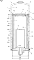
- FIG. 1 An accumulator according to the first embodiment of the present invention will be described with reference to FIG. 1 to FIG. 3 .
- the near side of the paper plane of FIG. 1 is assumed to be a front face side (front side) of the accumulator, and a description will be made on the basis of the up and down and right and left directions when viewed from the front side.
- An accumulator 1 is used, for example, in a hydraulic system for motor vehicle, a hydraulic system for industrial equipment or the like, as a pressure accumulation device, a pulsation damping device or the like, and is a metal bellows accumulator using a metal bellows as a bellows body 31.
- the accumulator 1 is comprises of a housing 2 and a bellows 3 housed in the housing 2.
- FIG. 1 shows a state that the bellows body 31 (described later) is expanded due to liquid storage or the like.
- the housing 2 is provided with a bottomed cylindrical shell 21 whose lower end opens and an oil port member 22 which is welded and fixed thereto so as to close the lower end of the shell 21.
- the bellows 3 is comprises the metallic bellows body 31 forming a generally cylindrical shape whose both upper and lower ends are opened, and a metallic bellows cap 32 forming a disc shape.
- a metallic stay 37 forming a bottomed cylindrical shape whose lower end is opened is provided inside the bellows 3 housed in the housing 2.
- the bellows body 31 is welded and fixed to an inner surface 22b of the oil port member 22 so as to close a fixed end 31a constituting the lower end thereof, and the bellows cap 32 is welded and fixed thereto in a state that an annular guard ring 33 is sandwiched therebetween so as to close a loose end 31b constituting the upper end thereof.
- an annular damping ring 34 is attached such that the bellows body 31 and the bellows cap 32 do not directly contact against an inner wall surface 21b of the shell 21.
- an outer peripheral surface 34a of the damping ring 34 and the inner wall surface 21b of the shell 21 are slightly spaced in a radial direction, and can smoothly slide without impeding expansion and contraction of the bellows 3.
- the stay 37 is provided on the inner side of the bellows body 31, and is welded and fixed to the inner surface 22b of the oil port member 22 so as to close a fixed end 37a constituting the lower end thereof. Moreover, in an end face part 37b constituting an upper end of the stay 37 and forming a disc shape, a liquid inlet and outlet 37c communicating with a hollow part 37d formed in the interior of the stay 37 is provided at the center in the radial direction.
- An interior space of the housing 2 is partitioned by the bellows 3 (the bellows body 31 and the bellows cap 32) in a sealed state into a gas chamber 4 communicating with the gas filling port 21a provided in the shell 21, and a liquid chamber 5 communicating with the oil port 22a provided in the oil port member 22 via the hollow part 37d and the liquid inlet and outlet 37c of the stay 37.
- the liquid chamber 5 is configured by the inner surface 22b of the oil port member 22, an inner peripheral surface 31d of the bellows body 31, the lower surface 32b (the gasket 36) of the bellows cap 32, and the end face part 37b and an outer peripheral surface 37e of the stay 37, and a liquid flows in and out of the pressure piping via the oil port 22a, the hollow part 37d of the stay 37, and the liquid inlet and outlet 37c of the stay 37.
- the accumulator 1 performs, by expansion and contraction of the bellows 3 housed in the housing 2, pressure regulation by moving the bellows cap 32 to a predetermined position and balancing gas pressure in the gas chamber 4 and liquid pressure in the liquid chamber 5.
- the bellows body 31 can expand and contract in the up and down direction.
- the bellows body 31 is a molded bellows, and the outer annular ridge portions 38, 38, ... and the inner annular ridge portions 39, 39, ... each projects generally uniformly in a circumferential direction.
- a region where there are the outer annular ridge portions 38, 38, ... having a diameter smaller than that of the fixed end 31a side is distributed in a center part in the expansion and contraction direction.
- first sector B1 and second sector A1 which are distributed in an expansion and contraction direction of the bellows body 31 such that the second sector A1 is positioned between the first sector B1 and the fixed end 31a, and the outer annular ridge portions 38, 38, ...included the first sector B1 have an outer diameter smaller than the diameter of the outer annular ridge portions 38, 38, included in the second sector A1, that is, an outer diameter OD2 of the bellows body 31 is smaller than an outer diameter OD1 thereof.
- the second sector A1 on the loose end 31b side of the bellows body 31 is configured so as to have the same outer diameter OD1 as the fixed end 31a side.
- the fixed end 31a of the bellows body 31 housed in the housing 2 is welded and fixed to the inner surface 22b of the oil port member 22, the fixed end 31a vibrates integrally with the same period as the shell 21, the oil port member 22, and the stay 37 as described above.
- the loose end 31b of the bellows body 31 housed in the housing 2 is suppressed from vibrating in the radial direction by the damping ring 34 attached to the bellows cap 32, but is slightly spaced in the radial direction from the outer peripheral surface 34a of the damping ring 34 and the inner wall surface 21b of the shell 21 as previously described, the outer peripheral surface 34a and the inner wall surface 21b repeat abutment while slightly vibrating in the radial direction within the vibrating shell 21. That is, the loose end 31b side of the bellows body 31 vibrates with a period different from the shell 21, the oil port member 22 and the stay 37, and further the fixed end 31a of the bellows body 31.
- the bellows 3 in the present embodiment is effective for the case of a secondary mode in resonance of a cantilever.
- the first sectors B1, B1 are configured such that the diameter of outer annular ridge portions 238B, 238B, ... which sandwich the second sector A1 including the center part in the expansion and contraction direction and are divided into upper and lower sectors is smaller than the diameter of outer annular ridge portions 238A, 238A, ... included in the second sectors A1, A1 on a fixed end 231a side and a loose end 231b side, that is, the outer diameter OD2 of the bellows body 231 is smaller than the outer diameter OD1 thereof.
- the first sectors B1, B1 where the outer diameter OD2 of the bellows body 231 is small are set by predicting the spot where amplitude amount of vibration is locally increased in accordance with the vibration condition in the radial direction of the bellows body 231 due to external vibration.
- the bellows body 231 of the present embodiment is configured such that the ratio of the first sector B1 where the outer annular ridge portions 238B, 238B, ... are distributed is smaller than that of the second sector A1 where the outer annular ridge portions 238A, 238A, ... are distributed, and increase and decrease of the capacity of the gas chamber 4 and the liquid chamber 5 in the housing 2 is suppressed, and therefore an effect on expansion and contraction of the bellows 3 during pressure regulation is reduced.
- the bellows 3 in the present embodiment is effective for the case of a tertiary mode in resonance of a cantilever.
- the bellows body 431 of the present embodiment is configured such that the ratio of the first sector B1 and the third sector B2 where the outer annular ridge portions 438B, 438B, ... and the inner annular ridge portions 439B, 439B, ... are distributed is smaller than that of the second sector A1 and the fourth sector A2 where the outer annular ridge portions438A, 438A, ... and the inner annular ridge portions 439A, 439A, ... are distributed, and increase and decrease of the capacity of the gas chamber 4 and the liquid chamber 5 in the housing 2 is suppressed, and therefore an effect on expansion and contraction of the bellows 3 during pressure regulation is reduced.
- the bellows 3 in the present embodiment is effective for the case of a secondary mode in resonance of a cantilever.
- the above embodiments have been described as the mode in which the gasket 36 is attached to the lower surface 32b of the bellows cap 32 and is brought into close contact with the end face portions 37b, 337b, 437b of the stays 37, 337, 437 during expansion and contraction of the bellows 3, but are not limited thereto, and the gasket may be attached to the end face part of the stay.
- bellows bodies 31, 231, 331, 431 are not limited to those made of metal, and may be formed of resin or the like, for example.
Landscapes
- Engineering & Computer Science (AREA)
- General Engineering & Computer Science (AREA)
- Mechanical Engineering (AREA)
- Physics & Mathematics (AREA)
- Fluid Mechanics (AREA)
- Supply Devices, Intensifiers, Converters, And Telemotors (AREA)
Claims (5)
- Hydraulikspeicher (1), umfassend: einen Balg (3), umfassend einen metallischen Balgkörper (31), der eine allgemein zylindrische Form bildet, deren oberes wie unteres Ende geöffnet sind, und eine metallische Kappe (32), die eine Scheibenform bildet, wobei der Balgkörper (31) mehrere äußere kranzförmige Rippenabschnitte (38) und mehrere innere kranzförmige Rippenabschnitte (39) aufweist und derart gestaltet ist, dass er in der Lage ist, sich auszuweiten und zusammenzuziehen, und ein Gehäuse (2), das mit einem zylindrischen Mantel (21) mit Boden, dessen unteres Ende sich öffnet, und mit einem Ölanschlusselement (22) versehen ist, das daran angeschweißt und befestigt ist, sodass das untere Ende des Mantel verschlossen ist, wobei das Ölanschlusselement (22) einen Fluidzufuhranschluss (22a) aufweist,wobei der Balgkörper
(31) an einer inneren Oberfläche (22b) des Ölanschlusselements (22) angeschweißt und befestigt ist, sodass ein fixiertes Ende (31a) verschlossen ist, das dessen unteres Ende bildet, und die Balgkappe (32) in einem Zustand daran angeschweißt und befestigt ist, dass ein kranzförmiger Schutzring (33) dazwischen eingelegt ist, sodass ein loses Ende (31b) verschlossen ist, das dessen oberes Ende bildet, wobei ein Inneres des Gehäuses in einem abgedichteten Zustand in eine Innenseite und eine Außenseite des Balgs unterteilt ist, wobeidie äußeren kranzförmigen Rippenabschnitte in mindestens einen ersten Sektor (Bl) und einen zweiten Sektor (Al) unterteilt sind, die in einer Ausweitungs- und Zusammenziehungsrichtung des Balgs verteilt sind, sodass der zweite Sektor zwischen dem ersten Sektor und dem fixierten Ende positioniert ist, und die äußeren kranzförmigen Rippenabschnitte (38B), die in dem ersten Sektor enthalten sind, einen Außendurchmesser aufweisen, der kleiner ist als der der äußeren kranzförmigen Rippenabschnitte (38A), die in dem zweiten Sektor (A1) enthalten sind,wobei ein kranzförmiger Dämpfungsring (34) an einem äußeren peripheren Abschnitt der Balgkappe angebracht ist, sodass der Balgkörper und die Balgkappe nicht direkt in Kontakt mit einer Innenwand-Oberfläche (21b) des Mantels stehen,eine äußere periphere Oberfläche (34a) des Dämpfungsrings und die Innenwand-Oberfläche des Mantels in radialer Richtung leicht beabstandet sind und gleichmäßig gleiten können, ohne die Ausweitung und Zusammenziehung des Balgs (3) zu behindern,wobei das lose Ende (31b) des Balgkörpers (31) in radialer Richtung von der äußeren peripheren Oberfläche (34a) des Dämpfungsrings (34) und der Innenwand-Oberfläche (21b) des Mantels (21) leicht beabstandet ist, und infolgedessen, wenn der Hydraulikspeicher externe Vibration aufnimmt, die äußere periphere Oberfläche und die Innenwand-Oberfläche wiederholt aneinander anliegen, während sie in der radialen Richtung innerhalb des vibrierenden Mantels leicht vibrieren. - Hydraulikspeicher nach Anspruch 1, dadurch gekennzeichnet, dass:
der erste Sektor in einem mittigen Teil in der Ausweitungs- und Zusammenziehungsrichtung des Balgs positioniert ist. - Hydraulikspeicher nach Anspruch 1 oder 2, dadurch gekennzeichnet, dass:
die äußeren kranzförmigen Rippenabschnitte des ersten Sektors derart verteilt sind, dass der Außendurchmesser der äußeren kranzförmigen Rippenabschnitte des ersten Sektors zum mittigen Teil in der Ausweitungs- und Zusammenziehungsrichtung des Balgs allmählich abnimmt. - Hydraulikspeicher nach einem der Ansprüche 1 bis 3, dadurch gekennzeichnet, dass er ferner eine Stütze (437) umfasst, die an dem Gehäuse fixiert ist und im Inneren des Balgs bereitgestellt ist, der in dem Gehäuse untergebracht ist, sodass ein Inneres des Balgs in der Lage ist, mit dem Fluidzufuhranschluss zu kommunizieren, wobei die inneren kranzförmigen Rippenabschnitte in mindestens einen dritten Sektor (B2) und einen vierten Sektor (A2) unterteilt sind, die in der Ausweitungs- und Zusammenziehungsrichtung des Balgs verteilt sind, sodass der vierte Sektor (A2) zwischen dem dritten Sektor (B2) und dem fixierten Ende (431a) positioniert ist, wobei die inneren kranzförmigen Rippenabschnitte (439B), die in dem dritten Sektor (B2) enthalten sind, einen Innendurchmesser (ID2) aufweisen, der größer ist als der (ID1) der inneren kranzförmigen Rippenabschnitte (439A), die in dem vierten Sektor (A2) enthalten sind.
- Hydraulikspeicher (301), umfassend: einen Balg (3), der mehrere äußere kranzförmige Rippenabschnitte und mehrere innere kranzförmige Rippenabschnitte (339A,339B) aufweist und derart gestaltet ist, dass er in der Lage ist, sich auszuweiten und zusammenzuziehen, und ein Gehäuse(2), das einen Fluidzufuhranschluss (22A) aufweist
und an einem Ende des Balgs fixiert ist, das als ein fixiertes Ende (331a) dient, wobei ein Inneres des Gehäuses in einem abgedichteten Zustand in eine Innenseite und eine Außenseite des Balgs unterteilt ist, wobei der Hydraulikspeicher ferner Folgendes umfasst:
eine Stütze (337), die an dem Gehäuse fixiert ist und im Inneren des Balgs bereitgestellt ist, der in dem Gehäuse untergebracht ist, sodass ein Inneres des Balgs in der Lage ist, mit dem Fluidzufuhranschluss in dem Balg zu kommunizieren, wobei die inneren kranzförmigen Rippenabschnitte in mindestens einen ersten Sektor (B2) und einen zweiten Sektor (A2) unterteilt sind, die in der Ausweitungs- und Zusammenziehungsrichtung des Balgs verteilt sind, sodass der zweite Sektor (A2) zwischen dem ersten Sektor (B2) und dem fixierten Ende (331a) positioniert ist, dadurch gekennzeichnet, dass die inneren kranzförmigen Rippenabschnitte (339B), die in dem ersten Sektor (B2) enthalten sind, einen Innendurchmesser (ID2) aufweisen, der größer ist als der (ID1) der inneren kranzförmigen Rippenabschnitte (339A), die in dem zweiten Sektor (A2) enthalten sind.
Applications Claiming Priority (2)
| Application Number | Priority Date | Filing Date | Title |
|---|---|---|---|
| JP2016235343 | 2016-12-02 | ||
| PCT/JP2017/040545 WO2018101007A1 (ja) | 2016-12-02 | 2017-11-10 | アキュムレータ |
Publications (3)
| Publication Number | Publication Date |
|---|---|
| EP3550156A1 EP3550156A1 (de) | 2019-10-09 |
| EP3550156A4 EP3550156A4 (de) | 2020-06-24 |
| EP3550156B1 true EP3550156B1 (de) | 2023-12-13 |
Family
ID=62242133
Family Applications (1)
| Application Number | Title | Priority Date | Filing Date |
|---|---|---|---|
| EP17875106.1A Active EP3550156B1 (de) | 2016-12-02 | 2017-11-10 | Akkumulator |
Country Status (5)
| Country | Link |
|---|---|
| US (1) | US10907657B2 (de) |
| EP (1) | EP3550156B1 (de) |
| JP (1) | JP6896763B2 (de) |
| CN (1) | CN109983237B (de) |
| WO (1) | WO2018101007A1 (de) |
Families Citing this family (3)
| Publication number | Priority date | Publication date | Assignee | Title |
|---|---|---|---|---|
| WO2018101007A1 (ja) * | 2016-12-02 | 2018-06-07 | イーグル工業株式会社 | アキュムレータ |
| CN112746993A (zh) * | 2020-12-30 | 2021-05-04 | 中国航空工业集团公司金城南京机电液压工程研究中心 | 一种可显示容积的两级波纹管式压力容器 |
| WO2022148946A1 (en) | 2021-01-11 | 2022-07-14 | Bae Systems Plc | A method and apparatus for modifying image |
Family Cites Families (21)
| Publication number | Priority date | Publication date | Assignee | Title |
|---|---|---|---|---|
| US781939A (en) * | 1903-02-26 | 1905-02-07 | Weston M Fulton | Collapsible vessel. |
| US3038553A (en) * | 1960-08-26 | 1962-06-12 | Melville F Peters | Flexible fluid coupling and sound attenuating assemblies |
| DE1756722A1 (de) * | 1968-07-03 | 1970-08-13 | Messerschmitt Boelkow Blohm | Druckentlastetes gasdichtes Gasfuehrungssystem von Luft- und Raumfahrzeugen |
| US4213545A (en) * | 1978-09-20 | 1980-07-22 | Textron, Inc. | Expanding bellows for expulsion tank |
| DE2910554A1 (de) | 1979-03-17 | 1980-09-25 | Bosch Gmbh Robert | Druckbehaelter |
| US4508373A (en) * | 1982-10-25 | 1985-04-02 | Ward Leslie M | Universal joint |
| JPS6065955A (ja) * | 1983-09-17 | 1985-04-15 | Mitsubishi Electric Corp | ベロ−ズ |
| DE3807316A1 (de) | 1988-03-05 | 1989-04-20 | Daimler Benz Ag | Hochdruckspeicher fuer hydraulische systeme |
| JPH02101102A (ja) | 1988-10-07 | 1990-04-12 | Sintokogio Ltd | 金型用型材 |
| JPH0741921Y2 (ja) * | 1989-01-30 | 1995-09-27 | エヌオーケー株式会社 | アキュムレータ |
| CN1092294C (zh) | 1997-09-29 | 2002-10-09 | 曹建钢 | 膜盒式蓄能器 |
| US6405760B1 (en) * | 2001-02-05 | 2002-06-18 | Perkinelmer, Inc. | Accumulator |
| JP2005155785A (ja) | 2003-11-26 | 2005-06-16 | Nok Corp | アキュムレータ |
| JP2007092782A (ja) | 2005-09-27 | 2007-04-12 | Nhk Spring Co Ltd | アキュムレータ |
| JP5715845B2 (ja) | 2011-02-15 | 2015-05-13 | イーグル工業株式会社 | アキュムレータ |
| EP2610881B1 (de) * | 2011-12-28 | 2014-04-30 | Siemens Aktiengesellschaft | Druckausgleicher für eine Unterwasservorrichtung |
| JP5872342B2 (ja) | 2012-03-22 | 2016-03-01 | イーグル工業株式会社 | アキュムレータ |
| CN104583606B (zh) | 2013-02-15 | 2017-03-29 | 伊格尔工业股份有限公司 | 蓄能器 |
| WO2015015873A1 (ja) | 2013-08-02 | 2015-02-05 | イーグル工業株式会社 | 金属ベローズ |
| CN107407296B (zh) | 2015-05-29 | 2019-11-29 | 伊格尔工业股份有限公司 | 金属波纹管式蓄压器 |
| WO2018101007A1 (ja) * | 2016-12-02 | 2018-06-07 | イーグル工業株式会社 | アキュムレータ |
-
2017
- 2017-11-10 WO PCT/JP2017/040545 patent/WO2018101007A1/ja not_active Ceased
- 2017-11-10 EP EP17875106.1A patent/EP3550156B1/de active Active
- 2017-11-10 US US16/464,650 patent/US10907657B2/en active Active
- 2017-11-10 JP JP2018553745A patent/JP6896763B2/ja active Active
- 2017-11-10 CN CN201780073091.3A patent/CN109983237B/zh active Active
Also Published As
| Publication number | Publication date |
|---|---|
| JPWO2018101007A1 (ja) | 2019-10-17 |
| CN109983237A (zh) | 2019-07-05 |
| WO2018101007A1 (ja) | 2018-06-07 |
| JP6896763B2 (ja) | 2021-06-30 |
| CN109983237B (zh) | 2020-12-29 |
| EP3550156A1 (de) | 2019-10-09 |
| US20190383309A1 (en) | 2019-12-19 |
| US10907657B2 (en) | 2021-02-02 |
| EP3550156A4 (de) | 2020-06-24 |
Similar Documents
| Publication | Publication Date | Title |
|---|---|---|
| CN108138803B (zh) | 蓄能器 | |
| EP3550156B1 (de) | Akkumulator | |
| US7770599B2 (en) | Accumulator | |
| EP3306108B1 (de) | Metallbalgartiger akkumulator | |
| US20120006438A1 (en) | Accumulator | |
| US7318452B2 (en) | Accumulator | |
| US9534655B2 (en) | Vibration damping device | |
| EP2910794B1 (de) | Akkumulator | |
| EP3306109B1 (de) | Metallbalgartiger akkumulator | |
| EP2865898B1 (de) | Akkumulator | |
| EP3591265A1 (de) | Faltenbalg | |
| JP5374435B2 (ja) | アキュムレータ | |
| US7810522B1 (en) | Accumulator | |
| CN107407297A (zh) | 蓄能器 | |
| EP2905517A1 (de) | Dichtungsvorrichtung | |
| JP2012167748A (ja) | アキュムレータ | |
| EP3118463B1 (de) | Akkumulator | |
| EP3404271B1 (de) | Akkumulator | |
| EP3597932B1 (de) | Akkumulator | |
| JP6774405B2 (ja) | 金属ベローズ型アキュムレータ | |
| US9689405B1 (en) | Hydraulic accumulator | |
| JP6479574B2 (ja) | 金属ベローズ型アキュムレータ |
Legal Events
| Date | Code | Title | Description |
|---|---|---|---|
| STAA | Information on the status of an ep patent application or granted ep patent |
Free format text: STATUS: THE INTERNATIONAL PUBLICATION HAS BEEN MADE |
|
| PUAI | Public reference made under article 153(3) epc to a published international application that has entered the european phase |
Free format text: ORIGINAL CODE: 0009012 |
|
| STAA | Information on the status of an ep patent application or granted ep patent |
Free format text: STATUS: REQUEST FOR EXAMINATION WAS MADE |
|
| 17P | Request for examination filed |
Effective date: 20190528 |
|
| AK | Designated contracting states |
Kind code of ref document: A1 Designated state(s): AL AT BE BG CH CY CZ DE DK EE ES FI FR GB GR HR HU IE IS IT LI LT LU LV MC MK MT NL NO PL PT RO RS SE SI SK SM TR |
|
| AX | Request for extension of the european patent |
Extension state: BA ME |
|
| DAV | Request for validation of the european patent (deleted) | ||
| DAX | Request for extension of the european patent (deleted) | ||
| A4 | Supplementary search report drawn up and despatched |
Effective date: 20200528 |
|
| RIC1 | Information provided on ipc code assigned before grant |
Ipc: F15B 1/10 20060101AFI20200520BHEP Ipc: F16J 3/04 20060101ALI20200520BHEP |
|
| STAA | Information on the status of an ep patent application or granted ep patent |
Free format text: STATUS: EXAMINATION IS IN PROGRESS |
|
| 17Q | First examination report despatched |
Effective date: 20211202 |
|
| GRAP | Despatch of communication of intention to grant a patent |
Free format text: ORIGINAL CODE: EPIDOSNIGR1 |
|
| STAA | Information on the status of an ep patent application or granted ep patent |
Free format text: STATUS: GRANT OF PATENT IS INTENDED |
|
| INTG | Intention to grant announced |
Effective date: 20230731 |
|
| GRAS | Grant fee paid |
Free format text: ORIGINAL CODE: EPIDOSNIGR3 |
|
| GRAA | (expected) grant |
Free format text: ORIGINAL CODE: 0009210 |
|
| STAA | Information on the status of an ep patent application or granted ep patent |
Free format text: STATUS: THE PATENT HAS BEEN GRANTED |
|
| AK | Designated contracting states |
Kind code of ref document: B1 Designated state(s): AL AT BE BG CH CY CZ DE DK EE ES FI FR GB GR HR HU IE IS IT LI LT LU LV MC MK MT NL NO PL PT RO RS SE SI SK SM TR |
|
| REG | Reference to a national code |
Ref country code: GB Ref legal event code: FG4D |
|
| REG | Reference to a national code |
Ref country code: CH Ref legal event code: EP |
|
| REG | Reference to a national code |
Ref country code: DE Ref legal event code: R096 Ref document number: 602017077563 Country of ref document: DE |
|
| REG | Reference to a national code |
Ref country code: IE Ref legal event code: FG4D |
|
| PG25 | Lapsed in a contracting state [announced via postgrant information from national office to epo] |
Ref country code: GR Free format text: LAPSE BECAUSE OF FAILURE TO SUBMIT A TRANSLATION OF THE DESCRIPTION OR TO PAY THE FEE WITHIN THE PRESCRIBED TIME-LIMIT Effective date: 20240314 |
|
| REG | Reference to a national code |
Ref country code: LT Ref legal event code: MG9D |
|
| PG25 | Lapsed in a contracting state [announced via postgrant information from national office to epo] |
Ref country code: LT Free format text: LAPSE BECAUSE OF FAILURE TO SUBMIT A TRANSLATION OF THE DESCRIPTION OR TO PAY THE FEE WITHIN THE PRESCRIBED TIME-LIMIT Effective date: 20231213 |
|
| REG | Reference to a national code |
Ref country code: NL Ref legal event code: MP Effective date: 20231213 |
|
| PG25 | Lapsed in a contracting state [announced via postgrant information from national office to epo] |
Ref country code: ES Free format text: LAPSE BECAUSE OF FAILURE TO SUBMIT A TRANSLATION OF THE DESCRIPTION OR TO PAY THE FEE WITHIN THE PRESCRIBED TIME-LIMIT Effective date: 20231213 |
|
| PG25 | Lapsed in a contracting state [announced via postgrant information from national office to epo] |
Ref country code: LT Free format text: LAPSE BECAUSE OF FAILURE TO SUBMIT A TRANSLATION OF THE DESCRIPTION OR TO PAY THE FEE WITHIN THE PRESCRIBED TIME-LIMIT Effective date: 20231213 Ref country code: GR Free format text: LAPSE BECAUSE OF FAILURE TO SUBMIT A TRANSLATION OF THE DESCRIPTION OR TO PAY THE FEE WITHIN THE PRESCRIBED TIME-LIMIT Effective date: 20240314 Ref country code: ES Free format text: LAPSE BECAUSE OF FAILURE TO SUBMIT A TRANSLATION OF THE DESCRIPTION OR TO PAY THE FEE WITHIN THE PRESCRIBED TIME-LIMIT Effective date: 20231213 Ref country code: BG Free format text: LAPSE BECAUSE OF FAILURE TO SUBMIT A TRANSLATION OF THE DESCRIPTION OR TO PAY THE FEE WITHIN THE PRESCRIBED TIME-LIMIT Effective date: 20240313 |
|
| REG | Reference to a national code |
Ref country code: AT Ref legal event code: MK05 Ref document number: 1640661 Country of ref document: AT Kind code of ref document: T Effective date: 20231213 |
|
| PG25 | Lapsed in a contracting state [announced via postgrant information from national office to epo] |
Ref country code: NL Free format text: LAPSE BECAUSE OF FAILURE TO SUBMIT A TRANSLATION OF THE DESCRIPTION OR TO PAY THE FEE WITHIN THE PRESCRIBED TIME-LIMIT Effective date: 20231213 |
|
| PG25 | Lapsed in a contracting state [announced via postgrant information from national office to epo] |
Ref country code: SE Free format text: LAPSE BECAUSE OF FAILURE TO SUBMIT A TRANSLATION OF THE DESCRIPTION OR TO PAY THE FEE WITHIN THE PRESCRIBED TIME-LIMIT Effective date: 20231213 Ref country code: RS Free format text: LAPSE BECAUSE OF FAILURE TO SUBMIT A TRANSLATION OF THE DESCRIPTION OR TO PAY THE FEE WITHIN THE PRESCRIBED TIME-LIMIT Effective date: 20231213 Ref country code: NO Free format text: LAPSE BECAUSE OF FAILURE TO SUBMIT A TRANSLATION OF THE DESCRIPTION OR TO PAY THE FEE WITHIN THE PRESCRIBED TIME-LIMIT Effective date: 20240313 Ref country code: NL Free format text: LAPSE BECAUSE OF FAILURE TO SUBMIT A TRANSLATION OF THE DESCRIPTION OR TO PAY THE FEE WITHIN THE PRESCRIBED TIME-LIMIT Effective date: 20231213 Ref country code: LV Free format text: LAPSE BECAUSE OF FAILURE TO SUBMIT A TRANSLATION OF THE DESCRIPTION OR TO PAY THE FEE WITHIN THE PRESCRIBED TIME-LIMIT Effective date: 20231213 Ref country code: HR Free format text: LAPSE BECAUSE OF FAILURE TO SUBMIT A TRANSLATION OF THE DESCRIPTION OR TO PAY THE FEE WITHIN THE PRESCRIBED TIME-LIMIT Effective date: 20231213 |
|
| PG25 | Lapsed in a contracting state [announced via postgrant information from national office to epo] |
Ref country code: IS Free format text: LAPSE BECAUSE OF FAILURE TO SUBMIT A TRANSLATION OF THE DESCRIPTION OR TO PAY THE FEE WITHIN THE PRESCRIBED TIME-LIMIT Effective date: 20240413 |
|
| PG25 | Lapsed in a contracting state [announced via postgrant information from national office to epo] |
Ref country code: CZ Free format text: LAPSE BECAUSE OF FAILURE TO SUBMIT A TRANSLATION OF THE DESCRIPTION OR TO PAY THE FEE WITHIN THE PRESCRIBED TIME-LIMIT Effective date: 20231213 Ref country code: AT Free format text: LAPSE BECAUSE OF FAILURE TO SUBMIT A TRANSLATION OF THE DESCRIPTION OR TO PAY THE FEE WITHIN THE PRESCRIBED TIME-LIMIT Effective date: 20231213 |
|
| PG25 | Lapsed in a contracting state [announced via postgrant information from national office to epo] |
Ref country code: SK Free format text: LAPSE BECAUSE OF FAILURE TO SUBMIT A TRANSLATION OF THE DESCRIPTION OR TO PAY THE FEE WITHIN THE PRESCRIBED TIME-LIMIT Effective date: 20231213 |
|
| PG25 | Lapsed in a contracting state [announced via postgrant information from national office to epo] |
Ref country code: SM Free format text: LAPSE BECAUSE OF FAILURE TO SUBMIT A TRANSLATION OF THE DESCRIPTION OR TO PAY THE FEE WITHIN THE PRESCRIBED TIME-LIMIT Effective date: 20231213 Ref country code: SK Free format text: LAPSE BECAUSE OF FAILURE TO SUBMIT A TRANSLATION OF THE DESCRIPTION OR TO PAY THE FEE WITHIN THE PRESCRIBED TIME-LIMIT Effective date: 20231213 Ref country code: RO Free format text: LAPSE BECAUSE OF FAILURE TO SUBMIT A TRANSLATION OF THE DESCRIPTION OR TO PAY THE FEE WITHIN THE PRESCRIBED TIME-LIMIT Effective date: 20231213 Ref country code: IT Free format text: LAPSE BECAUSE OF FAILURE TO SUBMIT A TRANSLATION OF THE DESCRIPTION OR TO PAY THE FEE WITHIN THE PRESCRIBED TIME-LIMIT Effective date: 20231213 Ref country code: IS Free format text: LAPSE BECAUSE OF FAILURE TO SUBMIT A TRANSLATION OF THE DESCRIPTION OR TO PAY THE FEE WITHIN THE PRESCRIBED TIME-LIMIT Effective date: 20240413 Ref country code: EE Free format text: LAPSE BECAUSE OF FAILURE TO SUBMIT A TRANSLATION OF THE DESCRIPTION OR TO PAY THE FEE WITHIN THE PRESCRIBED TIME-LIMIT Effective date: 20231213 Ref country code: CZ Free format text: LAPSE BECAUSE OF FAILURE TO SUBMIT A TRANSLATION OF THE DESCRIPTION OR TO PAY THE FEE WITHIN THE PRESCRIBED TIME-LIMIT Effective date: 20231213 Ref country code: AT Free format text: LAPSE BECAUSE OF FAILURE TO SUBMIT A TRANSLATION OF THE DESCRIPTION OR TO PAY THE FEE WITHIN THE PRESCRIBED TIME-LIMIT Effective date: 20231213 |
|
| PG25 | Lapsed in a contracting state [announced via postgrant information from national office to epo] |
Ref country code: PT Free format text: LAPSE BECAUSE OF FAILURE TO SUBMIT A TRANSLATION OF THE DESCRIPTION OR TO PAY THE FEE WITHIN THE PRESCRIBED TIME-LIMIT Effective date: 20240415 Ref country code: PL Free format text: LAPSE BECAUSE OF FAILURE TO SUBMIT A TRANSLATION OF THE DESCRIPTION OR TO PAY THE FEE WITHIN THE PRESCRIBED TIME-LIMIT Effective date: 20231213 |
|
| REG | Reference to a national code |
Ref country code: DE Ref legal event code: R097 Ref document number: 602017077563 Country of ref document: DE |
|
| PG25 | Lapsed in a contracting state [announced via postgrant information from national office to epo] |
Ref country code: DK Free format text: LAPSE BECAUSE OF FAILURE TO SUBMIT A TRANSLATION OF THE DESCRIPTION OR TO PAY THE FEE WITHIN THE PRESCRIBED TIME-LIMIT Effective date: 20231213 |
|
| PLBE | No opposition filed within time limit |
Free format text: ORIGINAL CODE: 0009261 |
|
| STAA | Information on the status of an ep patent application or granted ep patent |
Free format text: STATUS: NO OPPOSITION FILED WITHIN TIME LIMIT |
|
| PG25 | Lapsed in a contracting state [announced via postgrant information from national office to epo] |
Ref country code: SI Free format text: LAPSE BECAUSE OF FAILURE TO SUBMIT A TRANSLATION OF THE DESCRIPTION OR TO PAY THE FEE WITHIN THE PRESCRIBED TIME-LIMIT Effective date: 20231213 |
|
| PG25 | Lapsed in a contracting state [announced via postgrant information from national office to epo] |
Ref country code: SI Free format text: LAPSE BECAUSE OF FAILURE TO SUBMIT A TRANSLATION OF THE DESCRIPTION OR TO PAY THE FEE WITHIN THE PRESCRIBED TIME-LIMIT Effective date: 20231213 Ref country code: DK Free format text: LAPSE BECAUSE OF FAILURE TO SUBMIT A TRANSLATION OF THE DESCRIPTION OR TO PAY THE FEE WITHIN THE PRESCRIBED TIME-LIMIT Effective date: 20231213 |
|
| 26N | No opposition filed |
Effective date: 20240916 |
|
| REG | Reference to a national code |
Ref country code: CH Ref legal event code: PL |
|
| PG25 | Lapsed in a contracting state [announced via postgrant information from national office to epo] |
Ref country code: MC Free format text: LAPSE BECAUSE OF FAILURE TO SUBMIT A TRANSLATION OF THE DESCRIPTION OR TO PAY THE FEE WITHIN THE PRESCRIBED TIME-LIMIT Effective date: 20231213 |
|
| PG25 | Lapsed in a contracting state [announced via postgrant information from national office to epo] |
Ref country code: LU Free format text: LAPSE BECAUSE OF NON-PAYMENT OF DUE FEES Effective date: 20241110 |
|
| REG | Reference to a national code |
Ref country code: CH Ref legal event code: PL |
|
| GBPC | Gb: european patent ceased through non-payment of renewal fee |
Effective date: 20241110 |
|
| PG25 | Lapsed in a contracting state [announced via postgrant information from national office to epo] |
Ref country code: CH Free format text: LAPSE BECAUSE OF NON-PAYMENT OF DUE FEES Effective date: 20241130 |
|
| REG | Reference to a national code |
Ref country code: BE Ref legal event code: MM Effective date: 20241130 |
|
| PG25 | Lapsed in a contracting state [announced via postgrant information from national office to epo] |
Ref country code: FI Free format text: LAPSE BECAUSE OF FAILURE TO SUBMIT A TRANSLATION OF THE DESCRIPTION OR TO PAY THE FEE WITHIN THE PRESCRIBED TIME-LIMIT Effective date: 20231213 |
|
| PG25 | Lapsed in a contracting state [announced via postgrant information from national office to epo] |
Ref country code: GB Free format text: LAPSE BECAUSE OF NON-PAYMENT OF DUE FEES Effective date: 20241110 Ref country code: BE Free format text: LAPSE BECAUSE OF NON-PAYMENT OF DUE FEES Effective date: 20241130 |
|
| PG25 | Lapsed in a contracting state [announced via postgrant information from national office to epo] |
Ref country code: FR Free format text: LAPSE BECAUSE OF NON-PAYMENT OF DUE FEES Effective date: 20241130 |
|
| PG25 | Lapsed in a contracting state [announced via postgrant information from national office to epo] |
Ref country code: IE Free format text: LAPSE BECAUSE OF NON-PAYMENT OF DUE FEES Effective date: 20241110 |
|
| PGFP | Annual fee paid to national office [announced via postgrant information from national office to epo] |
Ref country code: DE Payment date: 20250930 Year of fee payment: 9 |
|
| PG25 | Lapsed in a contracting state [announced via postgrant information from national office to epo] |
Ref country code: HU Free format text: LAPSE BECAUSE OF FAILURE TO SUBMIT A TRANSLATION OF THE DESCRIPTION OR TO PAY THE FEE WITHIN THE PRESCRIBED TIME-LIMIT; INVALID AB INITIO Effective date: 20171110 |
|
| PG25 | Lapsed in a contracting state [announced via postgrant information from national office to epo] |
Ref country code: CY Free format text: LAPSE BECAUSE OF FAILURE TO SUBMIT A TRANSLATION OF THE DESCRIPTION OR TO PAY THE FEE WITHIN THE PRESCRIBED TIME-LIMIT; INVALID AB INITIO Effective date: 20171110 |