EP3550157A1 - Vérin hydraulique, système hydraulique et grue - Google Patents
Vérin hydraulique, système hydraulique et grue Download PDFInfo
- Publication number
- EP3550157A1 EP3550157A1 EP16925671.6A EP16925671A EP3550157A1 EP 3550157 A1 EP3550157 A1 EP 3550157A1 EP 16925671 A EP16925671 A EP 16925671A EP 3550157 A1 EP3550157 A1 EP 3550157A1
- Authority
- EP
- European Patent Office
- Prior art keywords
- cavity
- piston
- hydraulic fluid
- hydraulic
- cylinder body
- Prior art date
- Legal status (The legal status is an assumption and is not a legal conclusion. Google has not performed a legal analysis and makes no representation as to the accuracy of the status listed.)
- Granted
Links
Images

Classifications
-
- F—MECHANICAL ENGINEERING; LIGHTING; HEATING; WEAPONS; BLASTING
- F15—FLUID-PRESSURE ACTUATORS; HYDRAULICS OR PNEUMATICS IN GENERAL
- F15B—SYSTEMS ACTING BY MEANS OF FLUIDS IN GENERAL; FLUID-PRESSURE ACTUATORS, e.g. SERVOMOTORS; DETAILS OF FLUID-PRESSURE SYSTEMS, NOT OTHERWISE PROVIDED FOR
- F15B15/00—Fluid-actuated devices for displacing a member from one position to another; Gearing associated therewith
- F15B15/08—Characterised by the construction of the motor unit
- F15B15/14—Characterised by the construction of the motor unit of the straight-cylinder type
- F15B15/1423—Component parts; Constructional details
- F15B15/1466—Hollow piston sliding over a stationary rod inside the cylinder
-
- B—PERFORMING OPERATIONS; TRANSPORTING
- B66—HOISTING; LIFTING; HAULING
- B66C—CRANES; LOAD-ENGAGING ELEMENTS OR DEVICES FOR CRANES, CAPSTANS, WINCHES, OR TACKLES
- B66C23/00—Cranes comprising essentially a beam, boom, or triangular structure acting as a cantilever and mounted for translatory of swinging movements in vertical or horizontal planes or a combination of such movements, e.g. jib-cranes, derricks, tower cranes
- B66C23/54—Cranes comprising essentially a beam, boom, or triangular structure acting as a cantilever and mounted for translatory of swinging movements in vertical or horizontal planes or a combination of such movements, e.g. jib-cranes, derricks, tower cranes with pneumatic or hydraulic motors, e.g. for actuating jib-cranes on tractors
-
- B—PERFORMING OPERATIONS; TRANSPORTING
- B66—HOISTING; LIFTING; HAULING
- B66C—CRANES; LOAD-ENGAGING ELEMENTS OR DEVICES FOR CRANES, CAPSTANS, WINCHES, OR TACKLES
- B66C23/00—Cranes comprising essentially a beam, boom, or triangular structure acting as a cantilever and mounted for translatory of swinging movements in vertical or horizontal planes or a combination of such movements, e.g. jib-cranes, derricks, tower cranes
- B66C23/62—Constructional features or details
- B66C23/82—Luffing gear
-
- F—MECHANICAL ENGINEERING; LIGHTING; HEATING; WEAPONS; BLASTING
- F15—FLUID-PRESSURE ACTUATORS; HYDRAULICS OR PNEUMATICS IN GENERAL
- F15B—SYSTEMS ACTING BY MEANS OF FLUIDS IN GENERAL; FLUID-PRESSURE ACTUATORS, e.g. SERVOMOTORS; DETAILS OF FLUID-PRESSURE SYSTEMS, NOT OTHERWISE PROVIDED FOR
- F15B15/00—Fluid-actuated devices for displacing a member from one position to another; Gearing associated therewith
- F15B15/08—Characterised by the construction of the motor unit
- F15B15/14—Characterised by the construction of the motor unit of the straight-cylinder type
- F15B15/149—Fluid interconnections, e.g. fluid connectors, passages
Definitions
- the present disclosure relates to the field of engineering equipment, in particular to a hydraulic cylinder, a hydraulic system and a crane.
- Fig. 1 is a structural schematic diagram of a hydraulic cylinder of the related art.
- the hydraulic cylinder comprises a cylinder body 1', a piston 2' which is disposed in the cylinder body 1' and capable of moving along an axial direction of the cylinder body 1', and a piston rod connected on the piston 2'.
- the cylinder body 1' has a first cavity 4' positioned on one side of the piston 2' facing away from the piston rod 3', and a second cavity 5' positioned on one side of the piston 2' facing the piston rod 3'.
- the first cavity 4' and the second cavity 5' can introduce and discharge hydraulic fluid.
- a hydraulic system comprises the hydraulic cylinder, a box body for accommodating the hydraulic fluid and a pump for pressurizing the hydraulic fluid in the box body. Both the first cavity 4' and the second cavity 5' can be communicated with the pump, and both the first cavity 4' and the second cavity 5' can be communicated with the box body.
- the second cavity 5' discharges the hydraulic fluid therein into the box body, and the piston rod 3' extends out of the cylinder body 1'; and when the second cavity 5' is communicated with the pump to introduce the hydraulic fluid pressurized by the pump, the first cavity 4' discharges the hydraulic fluid therein into the box body, and the piston rod 3' retracts into the cylinder body 1'.
- the inner diameter of the first cavity 4' and the inner diameter of the cylinder body 1' are D respectively
- the outer diameter of the piston rod 3' is d
- S 2 l ⁇ (D 2 -d 2 )/4.
- the piston rod 3' is tubular, and the inner diameter of the piston 3' is d 1 .
- the maximum distance of the movement of the piston 2' along the axial direction of the cylinder body 1' is L.
- the larger the outer diameter of the piston rod 3' the larger the amount of change of the hydraulic fluid in the hydraulic cylinder in the process that the piston 3' moves in the cylinder body 1', and the larger the volume of the box body required for the corresponding hydraulic cylinder.
- the size of the hydraulic cylinder is continuously increased, and the outer diameter d of the piston rod 3' of the hydraulic cylinder also needs to be increased correspondingly, so it is necessary to equip a larger box body for the hydraulic cylinder to accommodate the hydraulic fluid.
- the present disclosure aims at providing a hydraulic cylinder, a hydraulic system and a crane to improve the problem that the amount of change of hydraulic fluid in the hydraulic cylinder is large in the moving process of a piston in the related art.
- the present disclosure provides a hydraulic cylinder, comprising:
- the hydraulic cylinder further comprises a connecting unit for fixing the second piston relative to the cylinder body, wherein the connecting unit is connected with the second piston and extends to the first piston, a first through hole for allowing the connecting unit to pass through is formed in the first piston, and the connecting unit passes through the first through hole and is connected with the the cavity wall of the first cavity.
- the connecting unit comprises a tubular piece, one end of the tubular piece near to the second piston is communicated with the accommodating cavity, one end of the tubular piece away from the second piston is used for inputting the hydraulic fluid into the accommodating cavity and discharging the hydraulic fluid in the accommodating cavity.
- a first channel for communicating the accommodating cavity with the tubular piece is arranged on the second piston.
- a first hole communicated with the end of the tubular piece away from the second piston is formed in the the cavity wall of the first cavity, and the first hole is used for inputting the hydraulic fluid into the accommodating cavity and discharging the hydraulic fluid in the accommodating cavity.
- the cylinder body has a third cavity formed between the first piston rod and the cylinder body, the third cavity is communicated with the end of the tubular piece away from the second piston, the third cavity can introduce and discharge the hydraulic fluid, when the third cavity introduces the hydraulic fluid to push the piston rod to retract into the cylinder body, the first cavity discharges the fluid, and when the first cavity introduces the hydraulic fluid to push the piston rod to extend out of the cylinder body, the third cavity discharges the hydraulic fluid.
- the cylinder body has a third cavity formed between the piston rod and the cylinder body, the third cavity can introduce and discharge the hydraulic fluid, when the third cavity introduces the hydraulic fluid to push the piston rod to retract into the cylinder body, the first cavity discharges the fluid, and when the first cavity introduces the hydraulic fluid to push the piston rod to extend out of the cylinder body, the third cavity discharges the hydraulic fluid.
- the third cavity is communicated with the accommodating cavity.
- a second hole for communicating the third cavity with the accommodating cavity is formed in the piston rod.
- a second channel for communicating the accommodating cavity with the third cavity is arranged on the first piston.
- the accommodating cavity is communicated with the first cavity.
- a second through hole for communicating the first cavity with the accommodating cavity is formed in the first piston.
- the present application further provides a hydraulic system, and the hydraulic system comprises:
- the hydraulic system has a first working state and a second working state, in the first working state, the first cavity and the pump are communicated to introduce the hydraulic fluid pressurized by the pump, and the accommodating cavity and the box body are communicated to discharge the hydraulic fluid in the accommodating cavity into the box body; and in the second working state, the first cavity and the box body are communicated to discharge the hydraulic fluid in the first cavity into the box body, and the accommodating cavity and the box body are communicated to introduce the hydraulic fluid pressurized by the pump.
- the present application further provides a crane, optionally comprising the above hydraulic system.
- the crane further comprises a boom, and the hydraulic cylinder is used for driving the bottom to rotate.
- the piston rod has the accommodating cavity capable of accommodating the hydraulic fluid.
- the accommodating cavity can discharge the hydraulic fluid, and the amount of increase of the hydraulic fluid in the hydraulic cylinder reduces the amount of the hydraulic fluid discharged by the accommodating cavity relative to the related art.
- the accommodating cavity can introduce the hydraulic fluid, and the amount of decrease of the hydraulic fluid in the hydraulic cylinder reduces the amount of the hydraulic fluid introduced by the accommodating cavity relative to the related art.
- the hydraulic cylinder in this embodiment improves the problem that the amount of change of the hydraulic fluid in the hydraulic cylinder is large in the moving process of the piston rod in the related art.
- 1' cylinder body; 2', piston; 3', piston rod; 4', first cavity; 5', second cavity; 1, cylinder body; 2, first piston; 3, piston rod; 4, accommodating cavity; 5, first cavity; 6, second cavity; 7, second piston; 8, connecting unit; 9, third cavity; 10, first channel; 11, first hole; 12, second through hole; 13, second channel; 14, pipeline; 15, second through hole; 30, hydraulic cylinder; 40, box body; 50, pump; and 60, reversing valve.
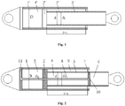
- Fig. 2 is a structural schematic diagram of a hydraulic cylinder of this embodiment.
- the hydraulic cylinder of this embodiment comprises a cylinder body 1, a first piston 2 which is disposed in the cylinder body 1 and capable of moving along an axial direction of the cylinder body 1, and a piston rod 3 with one end connected on the first piston 2 and extending along the axial direction of the cylinder body 1.
- the cylinder body 1 has a first cavity 5 positioned on one side of the first piston 2 facing away from the piston rod 3.
- the first cavity 5 can introduce hydraulic fluid to push the piston rod 3 to extend out of the cylinder body 1. In the process that the piston rod 3 retracts into the cylinder body 1, the first cavity 5 discharges the hydraulic fluid.
- the piston rod 3 has an accommodating cavity 4 capable of accommodating the hydraulic fluid.
- the accommodating cavity 4 can discharge the hydraulic fluid, and the amount of increase of the hydraulic fluid in the hydraulic cylinder reduces the amount of the hydraulic fluid discharged by the accommodating cavity 4 relative to the related art.
- the accommodating cavity 4 can introduce the hydraulic fluid, the amount of decrease of the hydraulic fluid in the hydraulic cylinder reduces the amount of the hydraulic fluid introduced by the accommodating cavity 4 relative to the related art.
- the hydraulic cylinder in this embodiment improves the problem that the amount of change of the hydraulic fluid in the hydraulic cylinder is large in the moving process of the piston rod 3 in the related art.
- the piston rod 3 has a second cavity 6 extending along the axial direction of the cylinder body 1, a second piston 7 capable of moving along the second cavity 6 is disposed in the second cavity 6, the second piston 7 is fixed relative to the cylinder body 1, and the accommodating cavity 4 comprises the part of the second cavity 6 positioned on one side of the second piston 7 facing the first piston 2.
- the accommodating cavity 4 is enclosed by the peripheral walls of the first piston 2, the second piston 7 and the second cavity 6.
- the piston rod 3 extends from the first piston 2 to the first end of the cylinder body 1, and the second piston 7 is disposed at the first end of the cylinder body 1 to prevent the second piston 7 from hindering the movement of the first piston 2 along the axial direction of the cylinder body 1.
- the surface of the second piston 7 facing the first piston 2 is flush with the inner end surface of the first end of the cylinder body 1; and further preferably, the surface of the second piston 7 facing the first piston 2 is farther away from the first piston 2 than the inner end surface of the first end of the cylinder body 1.
- An air vent is formed in the second cavity 6 which is positioned at the part of the second piston 7 facing away from the first piston 2 to enable the second piston 7 to smoothly move along the second cavity 6.
- the hydraulic cylinder further comprises a connecting unit 8 for fixing the second piston 7 relative to the cylinder body 1, wherein the connecting unit 8 is connected with the second piston 7 and extends to the first piston 2, a first through hole for allowing the connecting unit 8 to pass through is formed in the first piston 2, and the connecting unit 8 passes through the first through hole and is connected with the cavity wall of the first cavity 5.
- the cavity wall of the first cavity 5 comprises the end wall of the cylinder body 1, and one end of the connecting unit 8 away from the second piston 7 is connected with the end wall of the cylinder body 1.
- the connecting unit 8 comprises a tubular piece, one end of the tubular piece near to the second piston 7 is communicated with the accommodating cavity 4, one end of the tubular piece away from the second piston 7 is used for inputting the hydraulic fluid into the accommodating cavity 4 and discharging the hydraulic fluid in the accommodating cavity 4.
- a first channel 10 for communicating the accommodating cavity 4 with the tubular piece is arranged on the second piston 7.
- a first hole 11 communicated with the tubular piece is formed in the cavity wall of the first cavity 5.
- the first hole 11 extends from the outer surface of the cylinder body 1 into the end wall of the cylinder body 1, so as to communicate with the tubular piece.
- the cylinder body 1 has a third cavity 9 positioned on one side of the first piston 2 facing the piston rod 3.
- the third cavity 9 can introduce and discharge the hydraulic fluid.
- the third cavity 9 is an annular space between the first piston 2 and the end wall of the cylinder body 1.
- the third cavity 9 introduces the hydraulic fluid to push the piston rod 3 to retract into the cylinder body 1
- the distance between the first piston 2 and the second piston 7 is increased
- the volume of the accommodating cavity 4 is increased
- the accommodating cavity 4 introduces the hydraulic fluid
- the first cavity 5 discharges the hydraulic fluid at the same time.
- both the accommodating cavity 4 and the third cavity 9 discharge the hydraulic fluid.
- the inner diameter of the first cavity 5 and the inner diameter of the cylinder body 1 are D respectively
- the outer diameter of the connecting unit 8 positioned in the first cavity 5 is d 2
- the inner diameter of the third cavity 9 is equal to the diameter d of the piston rod 3, and the outer diameter of the third cavity 9 is equal to the inner diameter D of the cylinder body 1.
- the diameter of the accommodating cavity 4 is d 0
- the outer diameter of the connecting unit 8 positioned in the accommodating cavity 4 is d 2
- V 0 L ⁇ d 2 .
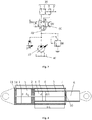
- Fig. 3 is a structural schematic diagram of a hydraulic system of this embodiment.
- the hydraulic system of this embodiment comprises the above hydraulic cylinder 30, a box body 40 for accommodating the hydraulic fluid and a pump 50 for pressurizing the hydraulic fluid in the box body 40.
- the pump 50 can convey the pressurized hydraulic fluid to the first cavity 5 to push the piston rod 3 to extend out of the cylinder body 1.
- the pump 50 can also convey the pressurized fluid to the accommodating cavity 4 and the third cavity 9 to push the piston rod 3 to retract into the cylinder body 1.
- the pressurized hydraulic fluid in the accommodating cavity 4 and the third cavity 9 can push the piston rod 3 to retract into the cylinder body 1, thereby increasing the driving force of the hydraulic cylinder.
- the hydraulic system of this embodiment further comprises a reversing valve 60, and the reversing valve 60 has a fluid inlet P, a backflow port T, a first working port A and a second working port B.
- the fluid inlet P is communicated with the pump 50
- the backflow port T is communicated with the box body 40
- the first working port A is communicated with the first cavity 5 of the hydraulic cylinder 30
- the second working port B is communicated with the third cavity 9 and the accommodating cavity 4 of the hydraulic cylinder 30.
- the second working port B is communicated with the first hole 11 in the hydraulic cylinder to realize the communication of the second working port and the accommodating cavity 4.
- the reversing valve 60 comprises a first state and a second state.
- the first working port A is in conduction with the fluid inlet P
- the second working port B is in conduction with the backflow port T.
- the pump 50 enables the pressurized hydraulic fluid to enter into the first cavity 5 of the hydraulic cylinder 30 to push the piston rod 3 to extend out of the cylinder body 1 and discharges the hydraulic fluid in the third cavity 9 and the accommodating cavity 4 to the box body 40.
- the first working port A is in conduction with the backflow port T
- the second working port B is in conduction with the fluid inlet P.
- the pump 50 enables the pressurized hydraulic fluid to respectively enter into the accommodating cavity 4 and the third cavity 9 to push the piston rod 3 to retract into the cylinder body 1, and discharges the hydraulic fluid discharged by the first cavity 5 to the box body 40.
- this embodiment further provides a crane, and the crane comprises the above hydraulic system.
- the above hydraulic cylinder 30 of the hydraulic fluid is used for driving a boom of the crane to rotate.
- Fig. 4 is a structural schematic diagram of a hydraulic cylinder of this embodiment. As shown in Fig. 4 , the hydraulic cylinder of this embodiment is different from the hydraulic cylinder of Embodiment 1 in that the hydraulic cylinder further comprises a pipeline 14 communicating the accommodating cavity 4 and the third cavity 9.
- the accommodating cavity 4 is communicated with the third cavity 9, when the first cavity 5 introduces the hydraulic fluid to push the piston rod 3 to extend out of the cylinder body 1, both the volume of the third cavity 9 and the volume of the accommodating cavity 4 are reduced, and both the third cavity 9 and the accommodating cavity 4 discharge the hydraulic fluid.
- the accommodating cavity 4 and the third cavity 9 can also introduce the hydraulic fluid to push the piston rod 3 to retract into the cylinder body 1, the volume of the first cavity 5 is correspondingly reduced, and the first cavity 5 discharges the hydraulic fluid.
- Fig. 5 is a structural schematic diagram of another implementation way of this embodiment. Referring to Fig. 5 , a second hole 12 communicating the third cavity 9 and the accommodating cavity 4 is formed in the piston rod 3, thereby realizing the communication of the third cavity 9 and the accommodating cavity 4.
- the second hole 12 is positioned at one end of the piston rod 3 near to the first piston 2.
- Fig. 6 is a structural schematic diagram of another implementation way of this embodiment. Referring to Fig. 6 , a second channel 13 for communicating the accommodating cavity 4 with the third cavity 9 is arranged on the first piston 2.
- Fig. 7 is a structural schematic diagram of a hydraulic cylinder of this embodiment. Referring to Fig. 7 , this embodiment is different from Embodiment 1 in that the accommodating cavity 4 is communicated with the first cavity 5.
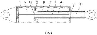
- a second through hole 15 communicating the first cavity 5 and the accommodating cavity 4 is formed in the second piston 2.
- the accommodating cavity 4 is communicated with the first cavity 5, and not communicated with the third cavity 9.
- the first cavity 5 introduces the hydraulic fluid to push the piston rod 3 to extend out of the cylinder body 1, the first piston 2 moves to the second piston 7, the volume of the accommodating cavity 4 is reduced, and the accommodating cavity 4 discharges the hydraulic fluid to the first cavity.
- the amount of the hydraulic fluid introduced by the first cavity 5 reduces the amount of the hydraulic fluid discharged by the accommodating cavity 4, and the amount of the hydraulic fluid discharged by the third cavity 9 is the same with that in the related art.
- the amount of change of the hydraulic fluid in the hydraulic cylinder is reduced relative to the related art.
- the problem that the amount of change of the hydraulic fluid in the hydraulic cylinder is large in the moving process of the piston rod 3 in the related art is improved.
- Fig. 8 is a structural schematic diagram of another preferred implementation way of this embodiment. As shown in Fig. 8 , the connecting unit 8 is arranged in the second through hole 15 by penetration, a gap exists between the connecting unit 8 and the peripheral surface of the second through hole 15 to communicate the accommodating cavity 4 with the first cavity 5.
Landscapes
- Engineering & Computer Science (AREA)
- Mechanical Engineering (AREA)
- Physics & Mathematics (AREA)
- Fluid Mechanics (AREA)
- General Engineering & Computer Science (AREA)
- Actuator (AREA)
Applications Claiming Priority (1)
| Application Number | Priority Date | Filing Date | Title |
|---|---|---|---|
| PCT/CN2016/113337 WO2018119971A1 (fr) | 2016-12-30 | 2016-12-30 | Vérin hydraulique, système hydraulique et grue |
Publications (3)
| Publication Number | Publication Date |
|---|---|
| EP3550157A1 true EP3550157A1 (fr) | 2019-10-09 |
| EP3550157A4 EP3550157A4 (fr) | 2020-06-24 |
| EP3550157B1 EP3550157B1 (fr) | 2023-11-01 |
Family
ID=62707760
Family Applications (1)
| Application Number | Title | Priority Date | Filing Date |
|---|---|---|---|
| EP16925671.6A Active EP3550157B1 (fr) | 2016-12-30 | 2016-12-30 | Vérin hydraulique, système hydraulique et grue |
Country Status (4)
| Country | Link |
|---|---|
| US (1) | US20190322497A1 (fr) |
| EP (1) | EP3550157B1 (fr) |
| AU (1) | AU2016434577A1 (fr) |
| WO (1) | WO2018119971A1 (fr) |
Family Cites Families (15)
| Publication number | Priority date | Publication date | Assignee | Title |
|---|---|---|---|---|
| US3335642A (en) * | 1965-01-08 | 1967-08-15 | Borje O Rosaen | Cylinder construction |
| US3447424A (en) * | 1967-09-19 | 1969-06-03 | Billings R O | Hydraulic cylinders having a quick exhaust |
| JPS4813691U (fr) * | 1971-07-03 | 1973-02-15 | ||
| US4867044A (en) * | 1984-11-26 | 1989-09-19 | The United States Of America As Represented By The Secretary Of The Navy | Jam resistant fluid power actuator for ballistic-damage tolerant redundant cylinder assemblies |
| DE4116399C2 (de) * | 1991-05-18 | 1995-07-13 | Hemscheidt Fahrwerktech Gmbh | Kolbenzylindereinheit insbesondere zur Verwendung als Federbein in Fahrzeug-Federungssystemen |
| FI99266C (fi) * | 1996-03-15 | 1998-02-10 | Tamrock Oy | Sovitelma paineväliainesylinterissä |
| JP2003004008A (ja) * | 2001-06-25 | 2003-01-08 | Ebara Corp | 水圧シリンダ |
| CN2709691Y (zh) * | 2004-06-29 | 2005-07-13 | 北汽福田汽车股份有限公司 | 一种自保护大速比液压缸 |
| JP4933862B2 (ja) * | 2006-08-24 | 2012-05-16 | 北都建機サービス株式会社 | 油圧駆動装置 |
| US20120325081A1 (en) * | 2010-12-22 | 2012-12-27 | Reed Vivatson | High power hydraulic cylinder |
| US8601934B1 (en) * | 2012-08-06 | 2013-12-10 | Westendorf Manufacturing Co., Inc. | Two piston cylinder |
| CN103787210A (zh) * | 2012-11-04 | 2014-05-14 | 西安志越机电科技有限公司 | 汽车起重机起升机构及其液压系统 |
| DE202014006861U1 (de) * | 2013-08-23 | 2014-12-01 | Hohenloher Spezial-Maschinenbau GmbH & Co. KG | Arbeitsmaschine |
| CN104806600B (zh) * | 2015-04-16 | 2017-08-08 | 徐州重型机械有限公司 | 一种变速液压缸 |
| CN104863910B (zh) * | 2015-05-24 | 2017-01-18 | 南京理工大学 | 一种重型长杆起重机构液压系统及控制方法 |
-
2016
- 2016-12-30 AU AU2016434577A patent/AU2016434577A1/en not_active Abandoned
- 2016-12-30 WO PCT/CN2016/113337 patent/WO2018119971A1/fr not_active Ceased
- 2016-12-30 US US16/474,845 patent/US20190322497A1/en not_active Abandoned
- 2016-12-30 EP EP16925671.6A patent/EP3550157B1/fr active Active
Also Published As
| Publication number | Publication date |
|---|---|
| WO2018119971A1 (fr) | 2018-07-05 |
| AU2016434577A1 (en) | 2019-07-18 |
| EP3550157A4 (fr) | 2020-06-24 |
| EP3550157B1 (fr) | 2023-11-01 |
| US20190322497A1 (en) | 2019-10-24 |
Similar Documents
| Publication | Publication Date | Title |
|---|---|---|
| CN105026111B (zh) | 具有同轴蓄能器和活塞的液压锤 | |
| US9822802B2 (en) | Accumulator membrane for a hydraulic hammer | |
| CN112320635B (zh) | 伸缩油缸的活塞杆、伸缩油缸以及起重机 | |
| US10472797B2 (en) | Two step hydraulic breaker with automatic stroke adjustment | |
| CN103256275A (zh) | 一种双作用快速液压缸 | |
| CN104847304A (zh) | 桥塞坐封工具 | |
| CN105829631B (zh) | 冲击工具 | |
| EP3550157B1 (fr) | Vérin hydraulique, système hydraulique et grue | |
| US20200040896A1 (en) | Screw compressor | |
| CN106640834A (zh) | 液压缸、液压系统和起重机 | |
| CN101900150A (zh) | 多级油缸及具有其的液压设备 | |
| JP2017078507A (ja) | 片ロッド形複動油圧シリンダ | |
| CN104265731A (zh) | 一种带有自锁止装置的液压缸 | |
| EP1717507A1 (fr) | Dispositif de lubrification pour outil hydraulique ou pneumatique | |
| JP2006105315A (ja) | 多段型の流体圧ジャッキ | |
| JP6721421B2 (ja) | 油圧ダウンザホールドリルの打撃機構 | |
| JP6643869B2 (ja) | 複数段流体圧シリンダ | |
| JP2017048842A (ja) | 片ロッド形複動油圧シリンダ | |
| CN115306790B (zh) | 液压缸、静力压桩机及压拔桩控制方法 | |
| CN211852373U (zh) | 一种两级独立控制油缸结构 | |
| CN102587824B (zh) | 高风压冲击器 | |
| CN210087728U (zh) | 伸缩缸和伸缩支架 | |
| JP2013133913A (ja) | 流体圧シリンダ | |
| CN104278949B (zh) | 用于反循环潜孔锤的加压流体流动系统和反循环潜孔锤 | |
| CN204082773U (zh) | 复合式棘爪自锁液压油缸 |
Legal Events
| Date | Code | Title | Description |
|---|---|---|---|
| STAA | Information on the status of an ep patent application or granted ep patent |
Free format text: STATUS: THE INTERNATIONAL PUBLICATION HAS BEEN MADE |
|
| PUAI | Public reference made under article 153(3) epc to a published international application that has entered the european phase |
Free format text: ORIGINAL CODE: 0009012 |
|
| STAA | Information on the status of an ep patent application or granted ep patent |
Free format text: STATUS: REQUEST FOR EXAMINATION WAS MADE |
|
| 17P | Request for examination filed |
Effective date: 20190701 |
|
| AK | Designated contracting states |
Kind code of ref document: A1 Designated state(s): AL AT BE BG CH CY CZ DE DK EE ES FI FR GB GR HR HU IE IS IT LI LT LU LV MC MK MT NL NO PL PT RO RS SE SI SK SM TR |
|
| AX | Request for extension of the european patent |
Extension state: BA ME |
|
| DAV | Request for validation of the european patent (deleted) | ||
| DAX | Request for extension of the european patent (deleted) | ||
| A4 | Supplementary search report drawn up and despatched |
Effective date: 20200528 |
|
| RIC1 | Information provided on ipc code assigned before grant |
Ipc: F15B 15/14 20060101AFI20200520BHEP Ipc: F15B 11/08 20060101ALI20200520BHEP Ipc: B66C 23/00 20060101ALI20200520BHEP |
|
| STAA | Information on the status of an ep patent application or granted ep patent |
Free format text: STATUS: EXAMINATION IS IN PROGRESS |
|
| 17Q | First examination report despatched |
Effective date: 20210430 |
|
| GRAP | Despatch of communication of intention to grant a patent |
Free format text: ORIGINAL CODE: EPIDOSNIGR1 |
|
| STAA | Information on the status of an ep patent application or granted ep patent |
Free format text: STATUS: GRANT OF PATENT IS INTENDED |
|
| INTG | Intention to grant announced |
Effective date: 20230519 |
|
| GRAS | Grant fee paid |
Free format text: ORIGINAL CODE: EPIDOSNIGR3 |
|
| GRAA | (expected) grant |
Free format text: ORIGINAL CODE: 0009210 |
|
| STAA | Information on the status of an ep patent application or granted ep patent |
Free format text: STATUS: THE PATENT HAS BEEN GRANTED |
|
| AK | Designated contracting states |
Kind code of ref document: B1 Designated state(s): AL AT BE BG CH CY CZ DE DK EE ES FI FR GB GR HR HU IE IS IT LI LT LU LV MC MK MT NL NO PL PT RO RS SE SI SK SM TR |
|
| REG | Reference to a national code |
Ref country code: GB Ref legal event code: FG4D |
|
| REG | Reference to a national code |
Ref country code: CH Ref legal event code: EP |
|
| REG | Reference to a national code |
Ref country code: DE Ref legal event code: R096 Ref document number: 602016083933 Country of ref document: DE |
|
| REG | Reference to a national code |
Ref country code: IE Ref legal event code: FG4D |
|
| REG | Reference to a national code |
Ref country code: LT Ref legal event code: MG9D |
|
| REG | Reference to a national code |
Ref country code: NL Ref legal event code: MP Effective date: 20231101 |
|
| PG25 | Lapsed in a contracting state [announced via postgrant information from national office to epo] |
Ref country code: GR Free format text: LAPSE BECAUSE OF FAILURE TO SUBMIT A TRANSLATION OF THE DESCRIPTION OR TO PAY THE FEE WITHIN THE PRESCRIBED TIME-LIMIT Effective date: 20240202 |
|
| PG25 | Lapsed in a contracting state [announced via postgrant information from national office to epo] |
Ref country code: IS Free format text: LAPSE BECAUSE OF FAILURE TO SUBMIT A TRANSLATION OF THE DESCRIPTION OR TO PAY THE FEE WITHIN THE PRESCRIBED TIME-LIMIT Effective date: 20240301 |
|
| PG25 | Lapsed in a contracting state [announced via postgrant information from national office to epo] |
Ref country code: LT Free format text: LAPSE BECAUSE OF FAILURE TO SUBMIT A TRANSLATION OF THE DESCRIPTION OR TO PAY THE FEE WITHIN THE PRESCRIBED TIME-LIMIT Effective date: 20231101 |
|
| REG | Reference to a national code |
Ref country code: AT Ref legal event code: MK05 Ref document number: 1627499 Country of ref document: AT Kind code of ref document: T Effective date: 20231101 |
|
| PG25 | Lapsed in a contracting state [announced via postgrant information from national office to epo] |
Ref country code: NL Free format text: LAPSE BECAUSE OF FAILURE TO SUBMIT A TRANSLATION OF THE DESCRIPTION OR TO PAY THE FEE WITHIN THE PRESCRIBED TIME-LIMIT Effective date: 20231101 |
|
| PG25 | Lapsed in a contracting state [announced via postgrant information from national office to epo] |
Ref country code: AT Free format text: LAPSE BECAUSE OF FAILURE TO SUBMIT A TRANSLATION OF THE DESCRIPTION OR TO PAY THE FEE WITHIN THE PRESCRIBED TIME-LIMIT Effective date: 20231101 |
|
| PG25 | Lapsed in a contracting state [announced via postgrant information from national office to epo] |
Ref country code: ES Free format text: LAPSE BECAUSE OF FAILURE TO SUBMIT A TRANSLATION OF THE DESCRIPTION OR TO PAY THE FEE WITHIN THE PRESCRIBED TIME-LIMIT Effective date: 20231101 |
|
| PG25 | Lapsed in a contracting state [announced via postgrant information from national office to epo] |
Ref country code: NL Free format text: LAPSE BECAUSE OF FAILURE TO SUBMIT A TRANSLATION OF THE DESCRIPTION OR TO PAY THE FEE WITHIN THE PRESCRIBED TIME-LIMIT Effective date: 20231101 Ref country code: LT Free format text: LAPSE BECAUSE OF FAILURE TO SUBMIT A TRANSLATION OF THE DESCRIPTION OR TO PAY THE FEE WITHIN THE PRESCRIBED TIME-LIMIT Effective date: 20231101 Ref country code: IS Free format text: LAPSE BECAUSE OF FAILURE TO SUBMIT A TRANSLATION OF THE DESCRIPTION OR TO PAY THE FEE WITHIN THE PRESCRIBED TIME-LIMIT Effective date: 20240301 Ref country code: GR Free format text: LAPSE BECAUSE OF FAILURE TO SUBMIT A TRANSLATION OF THE DESCRIPTION OR TO PAY THE FEE WITHIN THE PRESCRIBED TIME-LIMIT Effective date: 20240202 Ref country code: ES Free format text: LAPSE BECAUSE OF FAILURE TO SUBMIT A TRANSLATION OF THE DESCRIPTION OR TO PAY THE FEE WITHIN THE PRESCRIBED TIME-LIMIT Effective date: 20231101 Ref country code: BG Free format text: LAPSE BECAUSE OF FAILURE TO SUBMIT A TRANSLATION OF THE DESCRIPTION OR TO PAY THE FEE WITHIN THE PRESCRIBED TIME-LIMIT Effective date: 20240201 Ref country code: AT Free format text: LAPSE BECAUSE OF FAILURE TO SUBMIT A TRANSLATION OF THE DESCRIPTION OR TO PAY THE FEE WITHIN THE PRESCRIBED TIME-LIMIT Effective date: 20231101 Ref country code: PT Free format text: LAPSE BECAUSE OF FAILURE TO SUBMIT A TRANSLATION OF THE DESCRIPTION OR TO PAY THE FEE WITHIN THE PRESCRIBED TIME-LIMIT Effective date: 20240301 |
|
| PG25 | Lapsed in a contracting state [announced via postgrant information from national office to epo] |
Ref country code: SE Free format text: LAPSE BECAUSE OF FAILURE TO SUBMIT A TRANSLATION OF THE DESCRIPTION OR TO PAY THE FEE WITHIN THE PRESCRIBED TIME-LIMIT Effective date: 20231101 Ref country code: RS Free format text: LAPSE BECAUSE OF FAILURE TO SUBMIT A TRANSLATION OF THE DESCRIPTION OR TO PAY THE FEE WITHIN THE PRESCRIBED TIME-LIMIT Effective date: 20231101 Ref country code: PL Free format text: LAPSE BECAUSE OF FAILURE TO SUBMIT A TRANSLATION OF THE DESCRIPTION OR TO PAY THE FEE WITHIN THE PRESCRIBED TIME-LIMIT Effective date: 20231101 Ref country code: NO Free format text: LAPSE BECAUSE OF FAILURE TO SUBMIT A TRANSLATION OF THE DESCRIPTION OR TO PAY THE FEE WITHIN THE PRESCRIBED TIME-LIMIT Effective date: 20240201 Ref country code: LV Free format text: LAPSE BECAUSE OF FAILURE TO SUBMIT A TRANSLATION OF THE DESCRIPTION OR TO PAY THE FEE WITHIN THE PRESCRIBED TIME-LIMIT Effective date: 20231101 Ref country code: HR Free format text: LAPSE BECAUSE OF FAILURE TO SUBMIT A TRANSLATION OF THE DESCRIPTION OR TO PAY THE FEE WITHIN THE PRESCRIBED TIME-LIMIT Effective date: 20231101 |
|
| PG25 | Lapsed in a contracting state [announced via postgrant information from national office to epo] |
Ref country code: DK Free format text: LAPSE BECAUSE OF FAILURE TO SUBMIT A TRANSLATION OF THE DESCRIPTION OR TO PAY THE FEE WITHIN THE PRESCRIBED TIME-LIMIT Effective date: 20231101 |
|
| PG25 | Lapsed in a contracting state [announced via postgrant information from national office to epo] |
Ref country code: CZ Free format text: LAPSE BECAUSE OF FAILURE TO SUBMIT A TRANSLATION OF THE DESCRIPTION OR TO PAY THE FEE WITHIN THE PRESCRIBED TIME-LIMIT Effective date: 20231101 |
|
| PG25 | Lapsed in a contracting state [announced via postgrant information from national office to epo] |
Ref country code: SK Free format text: LAPSE BECAUSE OF FAILURE TO SUBMIT A TRANSLATION OF THE DESCRIPTION OR TO PAY THE FEE WITHIN THE PRESCRIBED TIME-LIMIT Effective date: 20231101 |
|
| PG25 | Lapsed in a contracting state [announced via postgrant information from national office to epo] |
Ref country code: SM Free format text: LAPSE BECAUSE OF FAILURE TO SUBMIT A TRANSLATION OF THE DESCRIPTION OR TO PAY THE FEE WITHIN THE PRESCRIBED TIME-LIMIT Effective date: 20231101 Ref country code: SK Free format text: LAPSE BECAUSE OF FAILURE TO SUBMIT A TRANSLATION OF THE DESCRIPTION OR TO PAY THE FEE WITHIN THE PRESCRIBED TIME-LIMIT Effective date: 20231101 Ref country code: RO Free format text: LAPSE BECAUSE OF FAILURE TO SUBMIT A TRANSLATION OF THE DESCRIPTION OR TO PAY THE FEE WITHIN THE PRESCRIBED TIME-LIMIT Effective date: 20231101 Ref country code: IT Free format text: LAPSE BECAUSE OF FAILURE TO SUBMIT A TRANSLATION OF THE DESCRIPTION OR TO PAY THE FEE WITHIN THE PRESCRIBED TIME-LIMIT Effective date: 20231101 Ref country code: EE Free format text: LAPSE BECAUSE OF FAILURE TO SUBMIT A TRANSLATION OF THE DESCRIPTION OR TO PAY THE FEE WITHIN THE PRESCRIBED TIME-LIMIT Effective date: 20231101 Ref country code: DK Free format text: LAPSE BECAUSE OF FAILURE TO SUBMIT A TRANSLATION OF THE DESCRIPTION OR TO PAY THE FEE WITHIN THE PRESCRIBED TIME-LIMIT Effective date: 20231101 Ref country code: CZ Free format text: LAPSE BECAUSE OF FAILURE TO SUBMIT A TRANSLATION OF THE DESCRIPTION OR TO PAY THE FEE WITHIN THE PRESCRIBED TIME-LIMIT Effective date: 20231101 |
|
| REG | Reference to a national code |
Ref country code: CH Ref legal event code: PL |
|
| REG | Reference to a national code |
Ref country code: DE Ref legal event code: R097 Ref document number: 602016083933 Country of ref document: DE |
|
| PG25 | Lapsed in a contracting state [announced via postgrant information from national office to epo] |
Ref country code: LU Free format text: LAPSE BECAUSE OF NON-PAYMENT OF DUE FEES Effective date: 20231230 |
|
| PG25 | Lapsed in a contracting state [announced via postgrant information from national office to epo] |
Ref country code: MC Free format text: LAPSE BECAUSE OF FAILURE TO SUBMIT A TRANSLATION OF THE DESCRIPTION OR TO PAY THE FEE WITHIN THE PRESCRIBED TIME-LIMIT Effective date: 20231101 |
|
| REG | Reference to a national code |
Ref country code: BE Ref legal event code: MM Effective date: 20231231 |
|
| PG25 | Lapsed in a contracting state [announced via postgrant information from national office to epo] |
Ref country code: MC Free format text: LAPSE BECAUSE OF FAILURE TO SUBMIT A TRANSLATION OF THE DESCRIPTION OR TO PAY THE FEE WITHIN THE PRESCRIBED TIME-LIMIT Effective date: 20231101 Ref country code: LU Free format text: LAPSE BECAUSE OF NON-PAYMENT OF DUE FEES Effective date: 20231230 |
|
| PLBE | No opposition filed within time limit |
Free format text: ORIGINAL CODE: 0009261 |
|
| STAA | Information on the status of an ep patent application or granted ep patent |
Free format text: STATUS: NO OPPOSITION FILED WITHIN TIME LIMIT |
|
| 26N | No opposition filed |
Effective date: 20240802 |
|
| REG | Reference to a national code |
Ref country code: IE Ref legal event code: MM4A |
|
| PG25 | Lapsed in a contracting state [announced via postgrant information from national office to epo] |
Ref country code: IE Free format text: LAPSE BECAUSE OF NON-PAYMENT OF DUE FEES Effective date: 20231230 |
|
| PG25 | Lapsed in a contracting state [announced via postgrant information from national office to epo] |
Ref country code: BE Free format text: LAPSE BECAUSE OF NON-PAYMENT OF DUE FEES Effective date: 20231231 |
|
| PG25 | Lapsed in a contracting state [announced via postgrant information from national office to epo] |
Ref country code: FR Free format text: LAPSE BECAUSE OF NON-PAYMENT OF DUE FEES Effective date: 20240101 |
|
| PG25 | Lapsed in a contracting state [announced via postgrant information from national office to epo] |
Ref country code: CH Free format text: LAPSE BECAUSE OF NON-PAYMENT OF DUE FEES Effective date: 20231231 |
|
| GBPC | Gb: european patent ceased through non-payment of renewal fee |
Effective date: 20240201 |
|
| PG25 | Lapsed in a contracting state [announced via postgrant information from national office to epo] |
Ref country code: SI Free format text: LAPSE BECAUSE OF FAILURE TO SUBMIT A TRANSLATION OF THE DESCRIPTION OR TO PAY THE FEE WITHIN THE PRESCRIBED TIME-LIMIT Effective date: 20231101 |
|
| PG25 | Lapsed in a contracting state [announced via postgrant information from national office to epo] |
Ref country code: SI Free format text: LAPSE BECAUSE OF FAILURE TO SUBMIT A TRANSLATION OF THE DESCRIPTION OR TO PAY THE FEE WITHIN THE PRESCRIBED TIME-LIMIT Effective date: 20231101 Ref country code: IE Free format text: LAPSE BECAUSE OF NON-PAYMENT OF DUE FEES Effective date: 20231230 Ref country code: FR Free format text: LAPSE BECAUSE OF NON-PAYMENT OF DUE FEES Effective date: 20240101 Ref country code: CH Free format text: LAPSE BECAUSE OF NON-PAYMENT OF DUE FEES Effective date: 20231231 Ref country code: BE Free format text: LAPSE BECAUSE OF NON-PAYMENT OF DUE FEES Effective date: 20231231 |
|
| PG25 | Lapsed in a contracting state [announced via postgrant information from national office to epo] |
Ref country code: GB Free format text: LAPSE BECAUSE OF NON-PAYMENT OF DUE FEES Effective date: 20240201 |
|
| PG25 | Lapsed in a contracting state [announced via postgrant information from national office to epo] |
Ref country code: GB Free format text: LAPSE BECAUSE OF NON-PAYMENT OF DUE FEES Effective date: 20240201 |
|
| PG25 | Lapsed in a contracting state [announced via postgrant information from national office to epo] |
Ref country code: FI Free format text: LAPSE BECAUSE OF FAILURE TO SUBMIT A TRANSLATION OF THE DESCRIPTION OR TO PAY THE FEE WITHIN THE PRESCRIBED TIME-LIMIT Effective date: 20231101 |
|
| PG25 | Lapsed in a contracting state [announced via postgrant information from national office to epo] |
Ref country code: CY Free format text: LAPSE BECAUSE OF FAILURE TO SUBMIT A TRANSLATION OF THE DESCRIPTION OR TO PAY THE FEE WITHIN THE PRESCRIBED TIME-LIMIT; INVALID AB INITIO Effective date: 20161230 |
|
| PG25 | Lapsed in a contracting state [announced via postgrant information from national office to epo] |
Ref country code: HU Free format text: LAPSE BECAUSE OF FAILURE TO SUBMIT A TRANSLATION OF THE DESCRIPTION OR TO PAY THE FEE WITHIN THE PRESCRIBED TIME-LIMIT; INVALID AB INITIO Effective date: 20161230 |
|
| PG25 | Lapsed in a contracting state [announced via postgrant information from national office to epo] |
Ref country code: TR Free format text: LAPSE BECAUSE OF FAILURE TO SUBMIT A TRANSLATION OF THE DESCRIPTION OR TO PAY THE FEE WITHIN THE PRESCRIBED TIME-LIMIT Effective date: 20231101 |
|
| PGFP | Annual fee paid to national office [announced via postgrant information from national office to epo] |
Ref country code: DE Payment date: 20251219 Year of fee payment: 10 |