EP3550204B1 - Leuchtvorrichtung für kraftfahrzeug, die eine schreibfunktion auf dem boden ausführt - Google Patents
Leuchtvorrichtung für kraftfahrzeug, die eine schreibfunktion auf dem boden ausführt Download PDFInfo
- Publication number
- EP3550204B1 EP3550204B1 EP19167065.2A EP19167065A EP3550204B1 EP 3550204 B1 EP3550204 B1 EP 3550204B1 EP 19167065 A EP19167065 A EP 19167065A EP 3550204 B1 EP3550204 B1 EP 3550204B1
- Authority
- EP
- European Patent Office
- Prior art keywords
- light
- pixels
- pixelized
- beams
- pixelated
- Prior art date
- Legal status (The legal status is an assumption and is not a legal conclusion. Google has not performed a legal analysis and makes no representation as to the accuracy of the status listed.)
- Active
Links
Images

Classifications
-
- F—MECHANICAL ENGINEERING; LIGHTING; HEATING; WEAPONS; BLASTING
- F21—LIGHTING
- F21S—NON-PORTABLE LIGHTING DEVICES; SYSTEMS THEREOF; VEHICLE LIGHTING DEVICES SPECIALLY ADAPTED FOR VEHICLE EXTERIORS
- F21S41/00—Illuminating devices specially adapted for vehicle exteriors, e.g. headlamps
-
- F—MECHANICAL ENGINEERING; LIGHTING; HEATING; WEAPONS; BLASTING
- F21—LIGHTING
- F21S—NON-PORTABLE LIGHTING DEVICES; SYSTEMS THEREOF; VEHICLE LIGHTING DEVICES SPECIALLY ADAPTED FOR VEHICLE EXTERIORS
- F21S41/00—Illuminating devices specially adapted for vehicle exteriors, e.g. headlamps
- F21S41/10—Illuminating devices specially adapted for vehicle exteriors, e.g. headlamps characterised by the light source
- F21S41/14—Illuminating devices specially adapted for vehicle exteriors, e.g. headlamps characterised by the light source characterised by the type of light source
- F21S41/141—Light emitting diodes [LED]
- F21S41/143—Light emitting diodes [LED] the main emission direction of the LED being parallel to the optical axis of the illuminating device
-
- B—PERFORMING OPERATIONS; TRANSPORTING
- B60—VEHICLES IN GENERAL
- B60Q—ARRANGEMENT OF SIGNALLING OR LIGHTING DEVICES, THE MOUNTING OR SUPPORTING THEREOF OR CIRCUITS THEREFOR, FOR VEHICLES IN GENERAL
- B60Q1/00—Arrangement of optical signalling or lighting devices, the mounting or supporting thereof or circuits therefor
- B60Q1/0017—Devices integrating an element dedicated to another function
-
- B—PERFORMING OPERATIONS; TRANSPORTING
- B60—VEHICLES IN GENERAL
- B60Q—ARRANGEMENT OF SIGNALLING OR LIGHTING DEVICES, THE MOUNTING OR SUPPORTING THEREOF OR CIRCUITS THEREFOR, FOR VEHICLES IN GENERAL
- B60Q1/00—Arrangement of optical signalling or lighting devices, the mounting or supporting thereof or circuits therefor
- B60Q1/02—Arrangement of optical signalling or lighting devices, the mounting or supporting thereof or circuits therefor the devices being primarily intended to illuminate the way ahead or to illuminate other areas of way or environments
- B60Q1/04—Arrangement of optical signalling or lighting devices, the mounting or supporting thereof or circuits therefor the devices being primarily intended to illuminate the way ahead or to illuminate other areas of way or environments the devices being headlights
- B60Q1/06—Arrangement of optical signalling or lighting devices, the mounting or supporting thereof or circuits therefor the devices being primarily intended to illuminate the way ahead or to illuminate other areas of way or environments the devices being headlights adjustable, e.g. remotely-controlled from inside vehicle
- B60Q1/08—Arrangement of optical signalling or lighting devices, the mounting or supporting thereof or circuits therefor the devices being primarily intended to illuminate the way ahead or to illuminate other areas of way or environments the devices being headlights adjustable, e.g. remotely-controlled from inside vehicle automatically
-
- F—MECHANICAL ENGINEERING; LIGHTING; HEATING; WEAPONS; BLASTING
- F21—LIGHTING
- F21S—NON-PORTABLE LIGHTING DEVICES; SYSTEMS THEREOF; VEHICLE LIGHTING DEVICES SPECIALLY ADAPTED FOR VEHICLE EXTERIORS
- F21S41/00—Illuminating devices specially adapted for vehicle exteriors, e.g. headlamps
- F21S41/10—Illuminating devices specially adapted for vehicle exteriors, e.g. headlamps characterised by the light source
- F21S41/14—Illuminating devices specially adapted for vehicle exteriors, e.g. headlamps characterised by the light source characterised by the type of light source
- F21S41/141—Light emitting diodes [LED]
- F21S41/151—Light emitting diodes [LED] arranged in one or more lines
- F21S41/153—Light emitting diodes [LED] arranged in one or more lines arranged in a matrix
-
- F—MECHANICAL ENGINEERING; LIGHTING; HEATING; WEAPONS; BLASTING
- F21—LIGHTING
- F21S—NON-PORTABLE LIGHTING DEVICES; SYSTEMS THEREOF; VEHICLE LIGHTING DEVICES SPECIALLY ADAPTED FOR VEHICLE EXTERIORS
- F21S41/00—Illuminating devices specially adapted for vehicle exteriors, e.g. headlamps
- F21S41/20—Illuminating devices specially adapted for vehicle exteriors, e.g. headlamps characterised by refractors, transparent cover plates, light guides or filters
- F21S41/24—Light guides
-
- F—MECHANICAL ENGINEERING; LIGHTING; HEATING; WEAPONS; BLASTING
- F21—LIGHTING
- F21S—NON-PORTABLE LIGHTING DEVICES; SYSTEMS THEREOF; VEHICLE LIGHTING DEVICES SPECIALLY ADAPTED FOR VEHICLE EXTERIORS
- F21S41/00—Illuminating devices specially adapted for vehicle exteriors, e.g. headlamps
- F21S41/20—Illuminating devices specially adapted for vehicle exteriors, e.g. headlamps characterised by refractors, transparent cover plates, light guides or filters
- F21S41/25—Projection lenses
- F21S41/255—Lenses with a front view of circular or truncated circular outline
-
- F—MECHANICAL ENGINEERING; LIGHTING; HEATING; WEAPONS; BLASTING
- F21—LIGHTING
- F21S—NON-PORTABLE LIGHTING DEVICES; SYSTEMS THEREOF; VEHICLE LIGHTING DEVICES SPECIALLY ADAPTED FOR VEHICLE EXTERIORS
- F21S41/00—Illuminating devices specially adapted for vehicle exteriors, e.g. headlamps
- F21S41/30—Illuminating devices specially adapted for vehicle exteriors, e.g. headlamps characterised by reflectors
- F21S41/32—Optical layout thereof
- F21S41/322—Optical layout thereof the reflector using total internal reflection
-
- F—MECHANICAL ENGINEERING; LIGHTING; HEATING; WEAPONS; BLASTING
- F21—LIGHTING
- F21S—NON-PORTABLE LIGHTING DEVICES; SYSTEMS THEREOF; VEHICLE LIGHTING DEVICES SPECIALLY ADAPTED FOR VEHICLE EXTERIORS
- F21S41/00—Illuminating devices specially adapted for vehicle exteriors, e.g. headlamps
- F21S41/60—Illuminating devices specially adapted for vehicle exteriors, e.g. headlamps characterised by a variable light distribution
-
- F—MECHANICAL ENGINEERING; LIGHTING; HEATING; WEAPONS; BLASTING
- F21—LIGHTING
- F21S—NON-PORTABLE LIGHTING DEVICES; SYSTEMS THEREOF; VEHICLE LIGHTING DEVICES SPECIALLY ADAPTED FOR VEHICLE EXTERIORS
- F21S41/00—Illuminating devices specially adapted for vehicle exteriors, e.g. headlamps
- F21S41/60—Illuminating devices specially adapted for vehicle exteriors, e.g. headlamps characterised by a variable light distribution
- F21S41/65—Illuminating devices specially adapted for vehicle exteriors, e.g. headlamps characterised by a variable light distribution by acting on light sources
- F21S41/663—Illuminating devices specially adapted for vehicle exteriors, e.g. headlamps characterised by a variable light distribution by acting on light sources by switching light sources
-
- B—PERFORMING OPERATIONS; TRANSPORTING
- B60—VEHICLES IN GENERAL
- B60Q—ARRANGEMENT OF SIGNALLING OR LIGHTING DEVICES, THE MOUNTING OR SUPPORTING THEREOF OR CIRCUITS THEREFOR, FOR VEHICLES IN GENERAL
- B60Q1/00—Arrangement of optical signalling or lighting devices, the mounting or supporting thereof or circuits therefor
-
- B—PERFORMING OPERATIONS; TRANSPORTING
- B60—VEHICLES IN GENERAL
- B60Q—ARRANGEMENT OF SIGNALLING OR LIGHTING DEVICES, THE MOUNTING OR SUPPORTING THEREOF OR CIRCUITS THEREFOR, FOR VEHICLES IN GENERAL
- B60Q2300/00—Indexing codes for automatically adjustable headlamps or automatically dimmable headlamps
- B60Q2300/10—Indexing codes relating to particular vehicle conditions
-
- B—PERFORMING OPERATIONS; TRANSPORTING
- B60—VEHICLES IN GENERAL
- B60Q—ARRANGEMENT OF SIGNALLING OR LIGHTING DEVICES, THE MOUNTING OR SUPPORTING THEREOF OR CIRCUITS THEREFOR, FOR VEHICLES IN GENERAL
- B60Q2400/00—Special features or arrangements of exterior signal lamps for vehicles
- B60Q2400/40—Welcome lights, i.e. specific or existing exterior lamps to assist leaving or approaching the vehicle
-
- B—PERFORMING OPERATIONS; TRANSPORTING
- B60—VEHICLES IN GENERAL
- B60Q—ARRANGEMENT OF SIGNALLING OR LIGHTING DEVICES, THE MOUNTING OR SUPPORTING THEREOF OR CIRCUITS THEREFOR, FOR VEHICLES IN GENERAL
- B60Q2400/00—Special features or arrangements of exterior signal lamps for vehicles
- B60Q2400/50—Projected symbol or information, e.g. onto the road or car body
-
- F—MECHANICAL ENGINEERING; LIGHTING; HEATING; WEAPONS; BLASTING
- F21—LIGHTING
- F21W—INDEXING SCHEME ASSOCIATED WITH SUBCLASSES F21K, F21L, F21S and F21V, RELATING TO USES OR APPLICATIONS OF LIGHTING DEVICES OR SYSTEMS
- F21W2102/00—Exterior vehicle lighting devices for illuminating purposes
- F21W2102/10—Arrangement or contour of the emitted light
- F21W2102/17—Arrangement or contour of the emitted light for regions other than high beam or low beam
- F21W2102/19—Arrangement or contour of the emitted light for regions other than high beam or low beam for curves
-
- F—MECHANICAL ENGINEERING; LIGHTING; HEATING; WEAPONS; BLASTING
- F21—LIGHTING
- F21W—INDEXING SCHEME ASSOCIATED WITH SUBCLASSES F21K, F21L, F21S and F21V, RELATING TO USES OR APPLICATIONS OF LIGHTING DEVICES OR SYSTEMS
- F21W2102/00—Exterior vehicle lighting devices for illuminating purposes
- F21W2102/20—Illuminance distribution within the emitted light
-
- F—MECHANICAL ENGINEERING; LIGHTING; HEATING; WEAPONS; BLASTING
- F21—LIGHTING
- F21W—INDEXING SCHEME ASSOCIATED WITH SUBCLASSES F21K, F21L, F21S and F21V, RELATING TO USES OR APPLICATIONS OF LIGHTING DEVICES OR SYSTEMS
- F21W2103/00—Exterior vehicle lighting devices for signalling purposes
- F21W2103/60—Projection of signs from lighting devices, e.g. symbols or information being projected onto the road
-
- H—ELECTRICITY
- H05—ELECTRIC TECHNIQUES NOT OTHERWISE PROVIDED FOR
- H05B—ELECTRIC HEATING; ELECTRIC LIGHT SOURCES NOT OTHERWISE PROVIDED FOR; CIRCUIT ARRANGEMENTS FOR ELECTRIC LIGHT SOURCES, IN GENERAL
- H05B45/00—Circuit arrangements for operating light-emitting diodes [LED]
- H05B45/10—Controlling the intensity of the light
Definitions
- the invention relates to the field of lighting and/or light signaling, in particular for motor vehicles. More particularly, the invention relates to a light device for a motor vehicle capable of projecting a pixelated light beam in order to project information on the road intended for the driver of the vehicle.
- the pixelated light beam In order for the information that this device projects onto the road to be clearly perceptible to the driver, it is necessary for the pixelated light beam to have a particularly high resolution.
- the documents FR 3 056 680 A1 And EP 3 248 838 A1 disclose a light system which is designed to project such a high resolution pixelated light beam.
- This function consists of modifying the light characteristics of the dipped type beam when the vehicle enters a bend to improve the driver's visibility in the bend without dazzling other road users. For example, the horizontal amplitude of the crossing-type beam is increased in the direction of the bend or the maximum intensity of the crossing-type beam is moved in the direction of the bend.
- the object of the invention is to overcome this problem and more specifically to propose a solution making it possible to project a pattern in a beam of the crossing type, this pattern remaining perceptible without sudden modification during the implementation of a lighting function. turning dynamics.
- the invention proposes a luminous device for a motor vehicle according to claim 1.
- the pattern is moved simultaneously with the displacement of the characteristics of the global beam, so that the contrast between the first and second light beams making it possible to generate this pattern remains constant when the dynamic lighting function turn is implemented. This guarantees the perceptibility of the pattern, without sudden variation in contrast.
- pixel width, and respectively length is meant the width, and respectively length, of this pixel when it is projected onto the road or onto a screen, for example placed 25 meters from the light device. These dimensions, measured in degrees, correspond to the angular apertures of the selectively activatable elementary beams which make up the first and second pixelated beams.
- the resolution of the first and second pixelated beams can thus be estimated by the number and the dimensions of the pixels composing these beams with respect to the amplitudes of these beams.
- the first light module can be arranged so that the first pixelated beam has at least 400 pixels, or even at least 1000 pixels, or even at least 2000 pixels.
- This first pixelated beam may for example comprise 20 columns and 20 rows of pixels, in particular 32 columns and 32 rows of pixels.
- the first module can be arranged so that each pixel of the first pixelated beam has a width and/or a length of less than 1°, in particular less than 0.5°, or even less than 0.3°.
- the first light module can be arranged so that the first pixelated beam has a vertical amplitude of at least 5°, in particular of at least 9°, and a horizontal amplitude of at least 5°, in particular of at least minus 12°.
- the optical projection element is arranged so that the pixelated beam has a vertical amplitude of at least 5° and a horizontal amplitude of at least 5°.
- These horizontal and vertical amplitudes make it possible to ensure that the pixelated beam is projected over an area of the road large enough to perform road writing functions by projecting a pattern in this pixelated beam, and in particular display functions ground marking, driving assistance and projection of GPS information, or even adaptive lighting functions requiring pixelation of the lighting beam and in particular lighting functions of the non-glare high beam type or of the dynamic cornering lighting type.
- the projection optical element can thus comprise one or a combination of several of the following optical components: lens, reflector, guide, collimator, prism.
- the pixelated light source may comprise at least 20 columns and at least 20 rows of elementary emitters, in particular at least 32 rows and columns of elementary emitters. These numbers of columns and minimum rows of elementary emitters, in combination with the vertical and horizontal amplitudes previously mentioned, make it possible to obtain, for each of the elementary light beams, a once projected by the optical projection element, an angular aperture of less than 0.5°, or even less than 0.3°. In this way, a minimum resolution of the pixelated beam is obtained when it is projected on the road such that a satisfactory perception of said pattern projected in the pixelated beam is guaranteed by a road user and/or by the driver of the vehicle as well crew.
- the elementary emitters and the optical projection element are arranged so that two neighboring pixels, that is to say two adjacent pixels on the same row or on the same column, are contiguous, that is that is, their adjacent edges coincide.
- the pixelated light source of the first module comprises at least one matrix of light-emitting elements (called a monolithic array) arranged in at least two columns by at least two rows.
- the light-emitting source comprises at least one matrix of monolithic light-emitting element matrix, also called monolithic matrix.
- the light-emitting elements are grown from a common substrate and are electrically connected so as to be selectively activatable, individually or by subset of light-emitting elements.
- each light-emitting element or group of light-emitting elements can form one of the elementary emitters of said pixelated light source which can emit light when its or their material is supplied with electricity
- light-emitting elements can meet this definition of monolithic matrix, provided that the light-emitting elements have one of their main dimensions of elongation substantially perpendicular to a common substrate and that the spacing between the elementary emitters, formed by one or more electroluminescent elements grouped together electrically, is small in comparison with the spacings imposed in known arrangements of flat square chips soldered on a printed circuit board.
- the substrate may mainly be made of semiconductor material.
- the substrate may comprise one or more other materials, for example non-semiconductors.
- Each electroluminescent rod here formed by using gallium nitride (GaN), extends perpendicularly, or substantially perpendicularly, projecting from the substrate, here made from silicon, other materials such as silicon carbide being able to be used without depart from the context of the invention.
- the light-emitting rods could be made from an alloy of aluminum nitride and gallium nitride (AIGaN), or from an alloy of aluminum phosphides, indium and gallium (AlInGaP).
- AIGaN alloy of aluminum nitride and gallium nitride
- AlInGaP aluminum phosphides
- Each electroluminescent rod extends along an axis of elongation defining its height, the base of each rod being arranged in a plane of the upper face of the substrate.
- the light-emitting rods of the same monolithic matrix advantageously have the same shape and the same dimensions. They are each delimited by an end face and by a circumferential wall which extends along the axis of elongation of the rod.
- the resulting light at the output of the semiconductor source is emitted essentially from the circumferential wall, it being understood that light rays can also come out from the face terminal.
- each light-emitting rod acts as a single light-emitting diode and the luminance of this source is improved on the one hand by the density of the light-emitting rods present and on the other hand by the size of the illuminating surface defined by the circumferential wall. and which therefore extends over the entire circumference, and the entire height, of the rod.
- the height of a rod can be between 2 and 10 ⁇ m, preferably 8 ⁇ m; the largest dimension of the end face of a rod is less than 2 ⁇ m, preferably less than or equal to 1 ⁇ m.
- the height can be modified from one zone of the pixelated light source to another, so as to increase the luminance of the corresponding zone when the average height of the rods constituting it is increased.
- a group of light-emitting rods can have a different height, or heights, from another group of light-emitting rods, these two groups being constitutive of the same semiconductor light source comprising light-emitting rods of sub-millimeter dimensions.
- the shape of the light-emitting rods can also vary from one monolithic matrix to another, in particular on the section of the rods and on the shape of the end face.
- the rods have a generally cylindrical shape, and they may in particular have a polygonal section shape, and more particularly hexagonal. We understand that it is important that light can be emitted through the circumferential wall, whether the latter has a polygonal or circular shape.
- the end face may have a substantially planar shape perpendicular to the circumferential wall, so that it extends substantially parallel to the upper face of the substrate, or it may have a rounded or pointed shape at its center. , so as to multiply the directions of emission of the light emerging from this end face.
- the light-emitting rods are arranged in a two-dimensional array. This arrangement could be such that the sticks are staggered.
- the rods are arranged at regular intervals on the substrate and the separation distance of two immediately adjacent electroluminescent rods, in each of the dimensions of the matrix, must be at least equal to 2 ⁇ m, preferably between 3 ⁇ m and 10 ⁇ m, so that the light emitted from the circumferential wall of each rod can exit the array of light-emitting rods.
- the monolithic matrix may comprise light-emitting elements formed by layers of epitaxial light-emitting elements, in particular a first n-doped GaN layer and a second p-doped GaN layer, on a single substrate, for example silicon carbide, and which is cut (by grinding and/or ablation) to form a plurality of elementary emitters respectively originating from the same substrate.
- a single substrate for example silicon carbide
- the result of such a design is a plurality of light-emitting blocks all originating from the same substrate and electrically connected to be selectively activatable from each other.
- the substrate of the monolithic matrix may have a thickness of between 100 ⁇ m and 800 ⁇ m, in particular equal to 200 ⁇ m; each block can have a width and width, each being between 50 ⁇ m and 500 ⁇ m, preferably between 100 ⁇ m and 200 ⁇ m. Alternatively, the length and the width are equal.
- the height of each block is less than 500 ⁇ m, preferably less than 300 ⁇ m.
- the exit surface of each block can be made via the substrate on the side opposite to the epitaxy.
- the distance between each contiguous elementary emitter can be less than 1 ⁇ m, in particular less than 500 nm, and it is preferably less than 200 nm.
- the monolithic matrix may further comprise a layer of a polymer material in which the light-emitting elements are at least partially embedded.
- the layer can thus extend over the entire extent of the substrate or only around a determined group of light-emitting elements.
- the polymer material which may in particular be based on silicone, creates a protective layer which makes it possible to protect the light-emitting elements without hindering the diffusion of the light rays.
- wavelength conversion means and for example phosphors, able to absorb at least part of the rays emitted by one of the elements and to convert at least a part of said excitation light absorbed into emission light having a wavelength different from that of the excitation light. It is possible to provide either that the phosphors are embedded in the mass of the polymer material, or that they are arranged on the surface of the layer of this polymer material.
- the pixelated light source may further comprise a coating of reflective material to deflect the light rays towards the output surfaces of the light source.
- the light-emitting elements of sub-millimeter dimensions define in a plane, substantially parallel to the substrate, a determined output surface. It will be understood that the shape of this output surface is defined according to the number and the arrangement of the light-emitting elements which compose it. It is thus possible to define a substantially rectangular shape of the emission surface, it being understood that the latter can vary and take any shape without departing from the context of the invention.
- the monolithic matrix(es) capable of emitting light rays can be coupled to the control unit.
- the control unit can be mounted on one or more of the matrices, the assembly thus forming a light sub-module.
- the control unit may comprise a central processing unit coupled with a memory on which is stored a computer program which includes instructions allowing the processor to carry out steps generating signals allowing the control of the light source .
- the control unit can be an integrated circuit, for example an ASIC (acronym for “Application-Specific Integrated Circuit”) or an ASSP (acronym for “Application Specifies Standard Product”).
- the pixelated light source can be formed by the assembly of at least one light source formed of at least one light-emitting diode emitting light and of a matrix of optoelectronic elements, and for example a matrix of micro-mirrors (also known by the acronym DMD, for English Digital Micromirror Device) which directs the light rays from said at least one light source by reflection towards the optical projection element.
- a matrix of micro-mirrors also known by the acronym DMD, for English Digital Micromirror Device
- an optical collection element makes it possible to collect the rays from the at least one light source in order to concentrate them and direct them towards the surface of the matrix of micro-mirrors.
- Each micro mirror can pivot between two fixed positions, a first position in which the light rays are reflected towards the projection optical element, and a second position in which the light rays are reflected in a direction different from the projection optical element .
- the two fixed positions are oriented in the same way for all the micro-mirrors and form with respect to a support reference plane of the matrix of micro-mirrors a characteristic angle of the matrix of micro-mirrors, defined in its specifications. This angle is generally less than 20° and is usually about 12°.
- each micro-mirror reflecting a small part of the light rays incident on the micro-mirror matrix forms an elementary emitter of the pixelated light source
- the actuation and the control of the change of position makes it possible to selectively activate this elementary emitter for whether or not to emit an elementary light beam
- the pixelated light source may be formed by a laser scanning system in which a laser source emits a laser beam towards scanning means configured to scan with the laser beam the surface of a wavelength converter element , surface which is imaged by the projection optical element.
- the scanning of the beam is accomplished by the scanning means at a sufficiently high speed for the human eye not to perceive its displacement in the projected image.
- the synchronized control of the switching on of the laser source and of the scanning movement of the beam makes it possible to generate a matrix of elementary emitters which can be selectively activated at the level of the surface of the wavelength converter element.
- the scanning means are a mobile micro-mirror, making it possible to scan the surface of the wavelength converter element by reflection of the laser beam.
- micro-mirrors mentioned as means of scanning are by example of the MEMS type (for “Micro-Electro-Mechanical Systems” in English or microelectromechanical system).
- the invention is in no way limited to this scanning means and can use other kinds of scanning means, such as a series of mirrors arranged on a rotating element, the rotation of the element generating a scanning of the surface transmission by the laser beam
- the second light module can be arranged so that the second beam of the pixelated crossing type has between 5 and 400 pixels, in particular 9 pixels.
- the second beam of the pixelated crossing type can present a single line of pixels, or in a variant, several lines of pixels arranged one above the other.
- the second module can be arranged so that each pixel of the second beam of the pixelated crossing type has a width and/or a length strictly greater than 0.5°, and in particular greater than 1°.
- the second light module can be arranged so that the second pixelated crossing type beam has a vertical amplitude of at least 5° and a horizontal amplitude of at least 15°.
- dipped type beam is meant a light beam intended to illuminate the road without dazzling other road users.
- the second light module is arranged so that the second beam of the pixelated crossing type has an upper cut-off of the crossing type, this upper cut-off being defined by the upper edges of the pixels making up the last upper line of this second light beam.
- the upper crossover-type cut may for example have a horizontal portion and an oblique portion.
- ECE regulation No. 123 in which a regulatory break is defined having a horizontal portion placed at 0.57° below the horizon and an oblique portion inclined at 15° with respect to the horizontal portion.
- the upper cut of the crossing type may comprise a single flat horizontal portion.
- the first and second light modules are arranged so that the first and second beams overlap so that the first pixelated beam extends in the global beam exclusively below the cutoff top of the second pixelated crossover type beam.
- the overall beam has an upper horizontal cutoff formed only by the upper horizontal cutoff of the second beam of the pixelated crossing type.
- the first pixelated beam is thus completely encompassed in the second beam of the pixelated crossing type, the vertical overlap is then total. This thus benefits from a projection zone entirely dedicated to a writing function on the road and it is guaranteed that in the event of a problem at the level of the first module, the entire dipped-beam lighting function is retained.
- the first and second light modules are arranged so that the first and second beams overlap so that the pixelated first beam extends into the overall beam above and below of the upper cutoff of the second pixelated crossover type beam.
- the portion of the first pixelated beam extending above the second pixelated crossing-type beam can produce a portion, for example oblique, of a crossing-type cutout intended to be associated with the upper cutoff of the second beam . In this case, this portion can for example be moved when the vehicle enters a bend to improve the performance of the dynamic bend lighting function.
- this portion of the first pixelated beam extending above the second beam of the pixelated crossing type can perform a lighting function of the selective road type.
- the second light module is arranged so that the second beam of pixelated crossing type extends horizontally in a substantially symmetrical manner on either side of a vertical axis and the first light module is arranged so that the first pixelated beam s extends horizontally in a substantially asymmetrical manner on either side of this vertical axis.
- This vertical axis can for example be a vertical axis intercepting the optical axis of said light device.
- the vertical axis can in particular pass through the junction of these two horizontal and oblique portions.
- the first pixelated beam can extend horizontally mainly on the outside-vehicle side, when the light device is mounted on the vehicle. It is thus guaranteed that the projection zone for the writing function on the ground is sufficiently large for the pattern to be able to be moved regardless of the curvature of the bend approached by the vehicle.
- the first and second light modules are arranged so that at least one edge of each pixel of the first pixelated beam coincides with an edge of a pixel of the second beam of the pixelated crossing type.
- Coincidence of edges of pixels is understood to mean a superimposition of these edges when the pixels are projected onto the road or onto a screen, for example placed 25 meters from the light device.
- the first and second light modules are arranged so that at least one vertical edge of each pixel of the second pixelated cross-type beam coincides with a vertical edge of a pixel of the first pixelated cross-type beam.
- the width of the pixels of the second beam is proportional to the width of the pixels of the first beam. It is thus possible to obtain an overlap of the first and second beams with interlacing of the pixels, so that the overall beam has satisfactory homogeneity, that is to say without any inhomogeneity between two pixels of the overall beam.
- control unit is arranged to selectively control, as a function of control instructions that it receives, the light intensity of said plurality of pixels of the first and second beams so that the pattern is projected into the global beam by an intensity difference between these pixels of the first and second light beams.
- Control of the light intensity of a pixel is understood to mean the switching on or off of this pixel as well as the under-intensification or over-intensification of the light intensity of this pixel.
- the pattern intended to be projected is defined by a dot matrix and the control unit is arranged to selectively control the light intensity of a plurality of pixels of the first and second beams located in a projection zone located at the overlap of the first and second beams so as to generate a contrast between each pair of pixels between the pixel of the first beam and the pixel of the second beam of this plurality of overlapping pixels, each contrast corresponding to a point of said dot matrix.
- the overlap of the first and second pixelated beams defines a matrix projection area which is controllable to display a pattern thereon.
- the pattern can be generated by positive contrasts, that is to say by positive intensity differences in each pair of pixels between the pixel of the first beam and the pixel of the second beam, for example by - intensification of the pixel of the first beam and/or by under-intensification of the pixel of the second beam.
- control unit is arranged to decrease the light intensity of all the pixels of the second beam of pixelated crossing type at the level of said projection zone. If applicable, the light intensity of the rest of the pixels of the second beam of pixelated crossing type, outside the projection zone, remains unchanged. This improves the contrast and therefore the perceptibility of the pattern with respect to the rest of the second beam of the pixelated crossing type.
- control unit is arranged to selectively control the light intensity of said plurality of pixels of the first and second beams located in the projection zone so as to shift each contrast between a pair of pixels of this plurality of pixels which overlap towards another pair of pixels of this plurality of pixels which overlap so as to create a displacement of said pattern in the global beam in the direction of the bend.
- displacement of a contrast from a first pair of pixels to a second pair of pixels is meant the control of this second pair of pixels so that the contrast of this second pair is substantially identical to that of the first pair. In this way, preservation of the contrast is thus guaranteed when the pattern is moved, so as not to disturb the driver.
- the light device comprises a third light module capable of projecting a third beam of the pixelated road type, the first and third light modules being arranged so that the first and third beams overlap at least partially vertically.
- the invention also relates to a light system for a motor vehicle, the system comprising a light device according to the invention as described above and a bend detection device intended to be approached by the motor vehicle, the unit control of the light device being arranged to receive information from said bend detection device and to control the pixels of the beams projected by the light modules of the light device as a function of said information.
- the detection device may in particular be a camera filming the road associated with image processing software, or even a steering wheel angle sensor.
- the system comprises a device for detecting vehicle traffic conditions and/or receiving information relating to vehicle traffic conditions, and the control unit is arranged to receive information relating to these traffic conditions from said detection and/or reception device and for selectively controlling said plurality of pixels of the first and second beams so as to project a pattern in the global beam relating to said traffic conditions.
- the detection and/or reception device can be a camera, a lidar, a GPS, or a wireless receiver.
- the traffic condition information detected or received may be the presence or absence of markings on the ground, an optimal trajectory of the vehicle to be taken, GPS navigation information, the presence of a road sign , the presence of an obstacle or danger, or the state of the traffic.
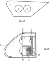
- FIG. 1A a light device 1 according to one embodiment of the invention.
- This light device comprises a first light module 2 capable of projecting a first pixelated beam HR and a second light module 3 capable of projecting a second beam of the pixelated crossing type LB.
- the first and second HR and LB pixelated beams have been shown in figure 1C , in projection on a screen placed 25 meters from the light device 1 and on which have been materialized a horizontal axis HH representing the horizon and a vertical axis VV, perpendicular to the horizontal axis HH and crossing the optical axis X of the device bright 1.
- This HR beam has a horizontal amplitude of 12° and a vertical amplitude of 9°. It extends asymmetrically on either side of the vertical axis V-V.
- the beam HR extends over 4° on the inside-vehicle side and over 8° on the outside-vehicle side. It also extends 4° above the horizontal H-H axis and 5° below the horizontal H-H axis.
- the light source 21 comprises a matrix of monolithic light-emitting elements, as described above.
- the first light module may comprise other elements than those previously described. These elements will not be described in the context of the present invention since they do not interact functionally with the arrangements according to the invention.
- This LB beam has a horizontal amplitude of 20° and a vertical amplitude of 8°.
- the second light module 3 is arranged so that the second beam of the pixelated crossing type has an upper cutoff of the crossing type LB_CO.
- the primary optical elements 32 are arranged so that their exit surfaces are abutted so that the lower edges of these surfaces are contiguous and aligned and the projection optical element 33 is focused on these exit surfaces. .
- the optical projection element 33 images these lower edges in an upper cutoff LB_CO, defined by the upper edges of the pixels making up this second light beam.
- the upper cut comprises a single flat horizontal portion, arranged at 0.57° below the horizontal axis HH.
- the second pixelated beam thus forms a pixelated crossing type beam.
- the resolution of the first pixelated beam HR is greater than the resolution of the second pixelated crossing type beam LB.
- the first and second light modules 2 and 3 are arranged so that the first and second beams HR and LB partially overlap vertically to form an overall beam LBG.
- the first pixelated beam HR thus extends above and below the upper cutoff LB_CO of the second pixelated crossing type beam LB.
- each vertical edge of each pixel of the second pixelated crossing type beam LB coincides with a vertical edge of a pixel of the first pixelated beam HR.
- the light device 1 comprises a control unit 4 capable of selectively controlling the light intensity of each of the pixels of the first and second beams HR and LB as a function of control instructions that it receives, for example by switching on, selectively turning off the elementary emitters of the light sources 21 and 31 or alternatively by varying the electrical power supplied to each of these elementary emitters in an increasing or decreasing manner.
- a control unit 4 capable of selectively controlling the light intensity of each of the pixels of the first and second beams HR and LB as a function of control instructions that it receives, for example by switching on, selectively turning off the elementary emitters of the light sources 21 and 31 or alternatively by varying the electrical power supplied to each of these elementary emitters in an increasing or decreasing manner.
- the overlapping of the first and second pixelated beams defines a matrix projection zone ZP formed by the overlapping of a plurality of pixels of the first and second pixelated beams HR and LB.
- Each pixel of the projection zone ZP is thus formed by a pair of a pixel of the first beam HR and of a pixel of the second beam LB which overlap each other.
- This pixel of the projection zone ZP can therefore be controlled by the control unit 4, by jointly controlling the light intensities of each pixel of the pair of pixels.
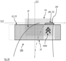
- FIG 2A a first operating mode of the luminous device 1 of the figures 1A to 1C .
- the vehicle equipped with the light device 1 travels on a straight line.
- This vehicle is equipped with a device for detecting a bend intended to be approached by the motor vehicle and a device for detecting and receiving information relating to the vehicle's traffic conditions.
- the bend detection device detects that the vehicle is traveling in a straight line, and the vehicle traffic condition information detection device receives GPS information to be transmitted to the driver via the light device 1.
- control unit 4 controls a plurality of pixels of the second beam of pixelated crossing type LB to illuminate the entire road, the rest of the pixels of this second beam LB therefore remaining off.
- control unit 4 controls a first plurality of pixels LBK of the first pixelated beam HR extending above the cutoff LB_CO to complete the second beam LB and form an oblique cutoff portion LBK_CO which is associated to the LB_CO cutoff to together form a regulatory crossover type cutoff profile.
- control unit 4 controls a second plurality of pixels HRM of the first pixelated beam HR in the projection zone ZP so as to create local light over-intensifications in the pixels of the second beam LB with which this second plurality of pixels HRMs overlap, with the rest of the pixels in the first pixelated beam remaining off.
- These over-intensifications thus create positive contrasts which consequently form a pattern in the projection area, which indicates to the driver the direction to follow.
- control unit 4 decreases the light intensity of the pixels of the second beam LB with which the second plurality of HRM pixels overlap.
- the control unit 4 thus performs an on-road write function.
- FIG 2B a second operating mode of the luminous device 1 of the figures 1A to 1C , succeeding the mode of operation of the figure 2A .
- the vehicle equipped with the light device 1 enters a bend.
- the bend detection device thus detects that the vehicle is approaching a bend.
- the control unit 4 In order to preserve the contrasts between the pixels of the first and second beams HR and LB at the level of the projection zone ZP which allow the driver to perceive the pattern, the control unit 4 then also moves the pattern in the direction of the bend by turning off progressively the second plurality of HRM pixels of the figure 2A and turning on another plurality of HRM pixels of the first HR pixelated beam on the bend side. As before, the control unit 4 decreases the light intensity of the pixels of the second beam LB with which the second plurality of pixels HRM overlap.
- the lighting device according to the invention makes it possible to retain the contrast characteristics making it possible to perceive the pattern, when the dynamic bend lighting function is implemented.
Landscapes
- Engineering & Computer Science (AREA)
- General Engineering & Computer Science (AREA)
- Physics & Mathematics (AREA)
- Microelectronics & Electronic Packaging (AREA)
- Optics & Photonics (AREA)
- Mechanical Engineering (AREA)
- Mathematical Physics (AREA)
- Lighting Device Outwards From Vehicle And Optical Signal (AREA)
- Non-Portable Lighting Devices Or Systems Thereof (AREA)
Claims (10)
- Leuchtvorrichtung (1) für ein Kraftfahrzeug, die ein erstes Leuchtmodul (2), das fähig ist, einen gemäß einer ersten Auflösung verpixelten ersten Strahl (HR) zu projizieren, und ein zweites Leuchtmodul (3) aufweist, das fähig ist, einen gemäß einer zweiten Auflösung verpixelten zweiten Strahl vom Typ Abblendlicht (LB) zu projizieren, wobei der zweite Strahl eine obere Hell-Dunkel-Grenze vom Typ Abblendlicht aufweist,wobei die ersten und zweiten Leuchtmodule so eingerichtet sind, dass die ersten und zweiten Strahlen sich zumindest teilweise senkrecht überdecken, um einen globalen Strahl (LBG) zu bilden, wobei die Überdeckung der ersten und zweiten verpixelten Strahlen (HR, LB) eine Matrixprojektionszone (ZP) definiert, die von der Überdeckung einer Vielzahl von Pixeln der ersten und zweiten verpixelten Strahlen gebildet wird,wobei die Vorrichtung eine Steuereinheit (4) aufweist, die fähig ist, selektiv eine Vielzahl von Pixeln (HRM) der ersten und zweiten Strahlen zu steuern, um ein Muster in den globalen Strahl zu projizieren,- wobei das Muster von einer Punktematrix definiert wird und die Steuereinheit (4) eingerichtet ist, um die Lichtstärke einer Vielzahl (HRM) von in der Projektionszone (ZP) befindlichen Pixeln der ersten und zweiten Strahlen (HR, LB) selektiv zu steuern, um in jedem Paar von Pixeln einen Kontrast zwischen dem Pixel des ersten Strahls (HR) und dem Pixel des zweiten Strahls (LB) dieser Vielzahl von sich überdeckenden Pixeln zu erzeugen, wobei jeder Kontrast einem Punkt der Punktematrix entspricht; und- wenn das Kraftfahrzeug sich einer Kurve nähert:o die Steuereinheit eingerichtet ist, um die Lichtstärke der Vielzahl (HRM) von in der Projektionszone (ZP) befindlichen Pixeln der ersten und zweiten Strahlen (HR, LB) selektiv zu steuern, um jeden Kontrast in einem Paar von Pixeln dieser Vielzahl von sich überdeckenden Pixeln zu einem anderen Paar von Pixeln dieser Vielzahl von sich überdeckenden Pixeln zu verschieben, um eine Verschiebung des Musters im globalen Strahl in Richtung der Kurve zu erzeugen;wobei die Leuchtvorrichtung dadurch gekennzeichnet ist, dass die zweite Auflösung niedriger ist als die erste Auflösung, und dasso die Steuereinheit (4) so eingerichtet ist, dass sie, wenn das Kraftfahrzeug sich einer Kurve nähert, die Pixel des ersten Strahls (HR) und/oder des zweiten Strahls (LB) steuert, um einen Teil einer oberen Hell-Dunkel-Grenze des globalen Strahls in Richtung der Kurve zu verschieben.
- Leuchtvorrichtung (1) nach dem vorhergehenden Anspruch, wobei die ersten und zweiten Leuchtmodule (2, 3) eingerichtet sind, damit:- der erste verpixelte Strahl (HR) eine größere Anzahl von Pixeln als die Anzahl von Pixeln des zweiten verpixelten Strahls vom Typ Abblendlicht (LB) aufweist; und/oder- jedes Pixel des ersten verpixelten Strahls eine Breite und/oder eine Länge strikt geringer als die minimale Breite und/oder die minimale Länge der Pixel des zweiten verpixelten Strahls vom Typ Abblendlicht aufweist;- der erste verpixelte Strahl eine waagrechte Amplitude geringer als die waagrechte Amplitude des zweiten verpixelten Strahls vom Typ Abblendlicht aufweist.
- Leuchtvorrichtung (1) nach dem vorhergehenden Anspruch, wobei die ersten und zweiten Leuchtmodule (2, 3) eingerichtet sind, damit die ersten und zweiten Strahlen (HR, LB) sich so überdecken, dass der erste verpixelte Strahl sich im globalen Strahl (LBG) ausschließlich unter der oberen Hell-Dunkel-Grenze (LB_CO) des zweiten verpixelten Strahls vom Typ Abblendlicht erstreckt.
- Leuchtvorrichtung (1) nach einem der Ansprüche 1 bis 2, wobei die ersten und zweiten Leuchtmodule (2, 3) eingerichtet sind, damit die ersten und zweiten Strahlen (HR, LB) sich so überdecken, dass der erste verpixelte Strahl sich im globalen Strahl (LBG) über und unter der oberen Hell-Dunkel-Grenze (LB_CO) des zweiten verpixelten Strahls vom Typ Abblendlicht erstreckt.
- Leuchtvorrichtung (1) nach dem vorhergehenden Anspruch, wobei der Teil des ersten verpixelten Strahls (HR), der sich über dem zweiten verpixelten Strahl vom Typ Abblendlicht (LB) erstreckt, einen Teil einer Hell-Dunkel-Grenze vom Typ Abblendlicht realisiert, der dazu bestimmt ist, der oberen Hell-Dunkel-Grenze des zweiten Strahls zugeordnet zu werden, und wobei der Teil, wenn das Fahrzeug sich einer Kurve nähert, in Richtung der Kurve verschoben wird.
- Leuchtvorrichtung (1) nach einem der vorhergehenden Ansprüche, wobei das zweite Leuchtmodul (3) eingerichtet ist, damit der zweite verpixelte Strahl vom Typ Abblendlicht (LB) sich waagrecht im Wesentlichen symmetrisch auf beiden Seiten einer senkrechten Achse (V-V) erstreckt, und das erste Leuchtmodul (2) eingerichtet ist, damit der erste verpixelte Strahl (HR) sich waagrecht im Wesentlichen unsymmetrisch zu beiden Seiten dieser senkrechten Achse erstreckt.
- Leuchtvorrichtung (1) nach einem der vorhergehenden Ansprüche, wobei die Steuereinheit (4) eingerichtet ist, um die Lichtstärke aller Pixel des zweiten verpixelten Strahls vom Typ Abblendlicht (LB) im Bereich der Projektionszone (ZP) zu verringern.
- Leuchtvorrichtung (1) nach einem der vorhergehenden Ansprüche, wobei das erste Leuchtmodul (2) eine monolithische Matrix von Elektrolumineszenzelementen (21) aufweist.
- Leuchtsystem für ein Kraftfahrzeug, wobei das System eine Leuchtvorrichtung (1) nach einem der vorhergehenden Ansprüche und eine Erkennungsvorrichtung einer Kurve aufweist, die dazu bestimmt ist, vom Kraftfahrzeug durchfahren zu werden, wobei die Steuereinheit (4) der Leuchtvorrichtung eingerichtet ist, um Informationen von der Kurvenerkennungsvorrichtung zu empfangen, und um die Pixel der von den Leuchtmodulen (2, 3) der Leuchtvorrichtung projizierten Strahlen (HR, LB) abhängig von den Informationen zu steuern.
- Leuchtsystem nach dem vorhergehenden Anspruch, dadurch gekennzeichnet, dass es eine Vorrichtung zur Erkennung von Verkehrsbedingungen des Fahrzeugs und/oder zum Empfang von Informationen bezüglich der Verkehrsbedingungen des Fahrzeugs aufweist, und dass die Steuereinheit (4) eingerichtet ist, um Informationen bezüglich dieser Verkehrsbedingungen von der Erkennungs- und/oder Empfangsvorrichtung zu empfangen und um die Vielzahl von Pixeln (HRM) der ersten und zweiten Strahlen (HR, LB) selektiv zu steuern, um ein Muster in den globalen Strahl (LBG) bezüglich der Verkehrsbedingungen zu projizieren.
Applications Claiming Priority (1)
| Application Number | Priority Date | Filing Date | Title |
|---|---|---|---|
| FR1852898A FR3079468B1 (fr) | 2018-04-03 | 2018-04-03 | Dispositif lumineux pour un vehicule automobile realisant une fonction d’ecriture au sol |
Publications (2)
| Publication Number | Publication Date |
|---|---|
| EP3550204A1 EP3550204A1 (de) | 2019-10-09 |
| EP3550204B1 true EP3550204B1 (de) | 2023-05-17 |
Family
ID=62528667
Family Applications (1)
| Application Number | Title | Priority Date | Filing Date |
|---|---|---|---|
| EP19167065.2A Active EP3550204B1 (de) | 2018-04-03 | 2019-04-03 | Leuchtvorrichtung für kraftfahrzeug, die eine schreibfunktion auf dem boden ausführt |
Country Status (5)
| Country | Link |
|---|---|
| US (2) | US10632896B2 (de) |
| EP (1) | EP3550204B1 (de) |
| JP (1) | JP7281947B2 (de) |
| CN (1) | CN110345441B (de) |
| FR (1) | FR3079468B1 (de) |
Families Citing this family (14)
| Publication number | Priority date | Publication date | Assignee | Title |
|---|---|---|---|---|
| FR3086723B1 (fr) * | 2018-09-28 | 2022-08-12 | Valeo Vision | Source lumineuse matricielle a gradation de l’intensite lumineuse |
| EP3670258A1 (de) * | 2018-12-18 | 2020-06-24 | ZKW Group GmbH | Lichtmodul-system und verfahren zum steuern des lichtmodul-systems |
| FR3101693A1 (fr) * | 2019-10-04 | 2021-04-09 | Valeo Vision | Procede d’adaptation de consignes pour une unite d’eclairage numerique d’un vehicule automobile |
| DE102019127406A1 (de) * | 2019-10-11 | 2021-04-15 | Bayerische Motoren Werke Aktiengesellschaft | Kraftfahrzeug mit einer Umfeldbeleuchtungseinrichtung |
| EP3825181B1 (de) * | 2019-11-21 | 2023-04-19 | Volvo Car Corporation | Fahrzeugaussenbeleuchtungsmodul |
| FR3104885B1 (fr) * | 2019-12-13 | 2022-08-05 | Valeo Vision | Procédé de gestion des données d'image et dispositif d'éclairage automobile |
| FR3105347A1 (fr) * | 2019-12-19 | 2021-06-25 | Valeo Vision | Dispositif lumineux apte à projeter deux faisceaux lumineux pixélisés |
| CN113124375A (zh) * | 2020-01-15 | 2021-07-16 | 华域视觉科技(上海)有限公司 | 车辆照明装置、车灯以及车辆 |
| FR3119221A1 (fr) * | 2021-01-22 | 2022-07-29 | Valeo Vision | Système d’éclairage de véhicule automobile muni d’un module lumineux apte à émettre un faisceau lumineux pixélisé |
| US12096160B2 (en) * | 2021-06-14 | 2024-09-17 | Hyundai Mobis Co., Ltd. | Light source control apparatus and lamp |
| DE102021117519A1 (de) * | 2021-07-07 | 2023-01-12 | Audi Aktiengesellschaft | Verfahren zum Projizieren eines Bildes mit mindestens einem Scheinwerfer eines Fahrzeugs auf eine Projektionsfläche |
| FR3132344B1 (fr) * | 2022-01-31 | 2024-01-05 | Valeo Vision | Système lumineux pour véhicule automobile |
| WO2023181815A1 (ja) * | 2022-03-22 | 2023-09-28 | 株式会社小糸製作所 | 車両用灯具システム、配光制御装置、および配光制御方法 |
| FR3161018A1 (fr) * | 2024-04-05 | 2025-10-10 | Valeo Vision | Dispositif d’éclairage d’un véhicule automobile. |
Citations (1)
| Publication number | Priority date | Publication date | Assignee | Title |
|---|---|---|---|---|
| EP3531010A1 (de) * | 2018-02-27 | 2019-08-28 | Valeo Vision | Leuchtvorrichtung für kraftfahrzeug und beleuchtungs- und/oder signalisierungseinheit, die mit einer solchen vorrichtung ausgestattet ist |
Family Cites Families (17)
| Publication number | Priority date | Publication date | Assignee | Title |
|---|---|---|---|---|
| CN100404357C (zh) * | 2004-10-07 | 2008-07-23 | 雅马哈发动机株式会社 | 二轮摩托车的照明灯的照射区域控制方法和该照明灯 |
| JP5255301B2 (ja) * | 2008-03-12 | 2013-08-07 | 株式会社小糸製作所 | 車両用前照灯装置 |
| JP5532310B2 (ja) * | 2010-03-25 | 2014-06-25 | スタンレー電気株式会社 | 車両用灯具 |
| JP6319943B2 (ja) * | 2013-03-28 | 2018-05-09 | 株式会社小糸製作所 | 車両用ランプ |
| JP6395393B2 (ja) * | 2014-02-13 | 2018-09-26 | 株式会社小糸製作所 | 車両の運転支援装置 |
| US10066799B2 (en) * | 2014-06-26 | 2018-09-04 | Texas Instruments Incorporated | Pixelated projection for automotive headlamp |
| JP5941111B2 (ja) * | 2014-09-30 | 2016-06-29 | 富士重工業株式会社 | 車両用前照灯装置 |
| FR3026820B1 (fr) * | 2014-10-02 | 2016-12-09 | Valeo Vision | Module d'eclairage pour un dispositif d'eclairage en bandes d'un projecteur pour vehicule automobile |
| EP3216650A4 (de) * | 2014-11-07 | 2018-06-13 | Dai Nippon Printing Co., Ltd. | Beleuchtungsvorrichtung |
| US20170106793A1 (en) * | 2015-10-19 | 2017-04-20 | Ford Global Technologies, Llc | Vehicle lighting system with dynamic beam pattern |
| EP3410888B1 (de) | 2016-02-01 | 2020-03-18 | PF Consumer Healthcare 1 LLC | Doppelendiger lippenbalsam-behälter |
| KR101770642B1 (ko) * | 2016-05-16 | 2017-09-05 | 엘지전자 주식회사 | 차량용 조명 장치 및 차량 |
| JP2017212169A (ja) * | 2016-05-27 | 2017-11-30 | 株式会社小糸製作所 | 車両用灯具 |
| KR101830663B1 (ko) * | 2016-07-06 | 2018-02-21 | 엘지전자 주식회사 | 차량용 램프 및 그것의 제어방법 |
| US10180224B2 (en) * | 2016-07-26 | 2019-01-15 | Texas Instruments Incorporated | Quasi-sparse optical illumination |
| FR3055947B1 (fr) * | 2016-09-15 | 2019-06-28 | Valeo Vision | Systeme optique de vehicule automobile |
| FR3056680B1 (fr) * | 2016-09-29 | 2018-11-09 | Valeo Vision | Systeme d'eclairage pour vehicule automobile |
-
2018
- 2018-04-03 FR FR1852898A patent/FR3079468B1/fr active Active
-
2019
- 2019-04-02 JP JP2019070697A patent/JP7281947B2/ja active Active
- 2019-04-03 EP EP19167065.2A patent/EP3550204B1/de active Active
- 2019-04-03 US US16/374,207 patent/US10632896B2/en active Active
- 2019-04-03 CN CN201910268324.6A patent/CN110345441B/zh active Active
-
2020
- 2020-03-17 US US16/821,695 patent/US11326752B2/en active Active
Patent Citations (1)
| Publication number | Priority date | Publication date | Assignee | Title |
|---|---|---|---|---|
| EP3531010A1 (de) * | 2018-02-27 | 2019-08-28 | Valeo Vision | Leuchtvorrichtung für kraftfahrzeug und beleuchtungs- und/oder signalisierungseinheit, die mit einer solchen vorrichtung ausgestattet ist |
Also Published As
| Publication number | Publication date |
|---|---|
| CN110345441A (zh) | 2019-10-18 |
| FR3079468B1 (fr) | 2020-03-20 |
| US11326752B2 (en) | 2022-05-10 |
| JP7281947B2 (ja) | 2023-05-26 |
| EP3550204A1 (de) | 2019-10-09 |
| JP2019204772A (ja) | 2019-11-28 |
| CN110345441B (zh) | 2022-11-08 |
| US10632896B2 (en) | 2020-04-28 |
| US20190299843A1 (en) | 2019-10-03 |
| US20200215960A1 (en) | 2020-07-09 |
| FR3079468A1 (fr) | 2019-10-04 |
Similar Documents
| Publication | Publication Date | Title |
|---|---|---|
| EP3550204B1 (de) | Leuchtvorrichtung für kraftfahrzeug, die eine schreibfunktion auf dem boden ausführt | |
| EP2690352B1 (de) | Adaptives Beleuchtungssystem für Kraftfahrzeug | |
| EP3775676A1 (de) | Beleuchtungsvorrichtung für ein kraftfahrzeug mit mindestens einer pixelierten lichtquelle | |
| EP3513234B1 (de) | Optisches system für einen gepixelten lichtstrahl | |
| EP3860877B1 (de) | Verfahren zur steuerung einer beleuchtungsvorrichtung zur emission eines blendfreien strahlenbündels zur beleuchtung einer strasse | |
| EP3342638B1 (de) | Beleuchtungsvorrichtung für ein fahrzeug, die zwei leuchtquellen kombiniert | |
| EP4281321B1 (de) | Kraftfahrzeugbeleuchtungssystem mit einem beleuchtungsmodul zur emission eines pixelierten lichtstrahls | |
| EP3376096B1 (de) | Leuchtvorrichtung, insbesondere zur beleuchtung und/oder signalisierung für kraftfahrzeug | |
| EP3775675A1 (de) | Monolithische kraftfahrzeugvorrichtung mit leuchtmatrixanordnung zum schreiben auf dem boden | |
| EP3399519B1 (de) | Leuchtmodul für ein kraftfahrzeug, das zum projizieren eines lichtstrahls konzipiert ist, der ein gepixeltes bild erzeugt | |
| FR3083942A1 (fr) | Systeme de communication optique sans fil pour vehicule | |
| FR3055979A1 (fr) | Caracteristiques de faisceau lumineux pixelise | |
| EP4285051B1 (de) | Kraftfahrzeugvorrichtung zur beleuchtung der strasse | |
| EP4045841B1 (de) | Lichtmodul für kraftfahrzeug | |
| FR3062217A1 (fr) | Aboutage de sources lumineuses pixelisees | |
| FR3084307A1 (fr) | Systeme d'eclairage pour vehicule automobile | |
| FR3082471A1 (fr) | Dispositif lumineux pour vehicule automobile | |
| EP3379141A1 (de) | Monolithische lichtquelle für ein leuchtmodul eines kraftfahrzeugs | |
| EP3502550A1 (de) | Segmentierter lichtstrahl, der beleuchtungsfunktionen erfüllt | |
| FR3086770A1 (fr) | Systeme optique de projection et module lumineux pour vehicule | |
| WO2026057748A1 (fr) | Module lumineux d'un dispositif d'éclairage d'un véhicule automobile | |
| FR3165056A1 (fr) | Dispositif lumineux pour véhicule automobile muni de deux modules lumineux réalisant des fonctions d’écriture sur route | |
| WO2023031344A1 (fr) | Dispositif lumineux d'un véhicule automobile | |
| FR3034058A1 (fr) | Module optique constitutif d'un dispositif d'eclairage et/ou de signalisation pour un vehicule automobile. |
Legal Events
| Date | Code | Title | Description |
|---|---|---|---|
| PUAI | Public reference made under article 153(3) epc to a published international application that has entered the european phase |
Free format text: ORIGINAL CODE: 0009012 |
|
| STAA | Information on the status of an ep patent application or granted ep patent |
Free format text: STATUS: THE APPLICATION HAS BEEN PUBLISHED |
|
| AK | Designated contracting states |
Kind code of ref document: A1 Designated state(s): AL AT BE BG CH CY CZ DE DK EE ES FI FR GB GR HR HU IE IS IT LI LT LU LV MC MK MT NL NO PL PT RO RS SE SI SK SM TR |
|
| AX | Request for extension of the european patent |
Extension state: BA ME |
|
| STAA | Information on the status of an ep patent application or granted ep patent |
Free format text: STATUS: REQUEST FOR EXAMINATION WAS MADE |
|
| 17P | Request for examination filed |
Effective date: 20200417 |
|
| RBV | Designated contracting states (corrected) |
Designated state(s): AL AT BE BG CH CY CZ DE DK EE ES FI FR GB GR HR HU IE IS IT LI LT LU LV MC MK MT NL NO PL PT RO RS SE SI SK SM TR |
|
| STAA | Information on the status of an ep patent application or granted ep patent |
Free format text: STATUS: EXAMINATION IS IN PROGRESS |
|
| 17Q | First examination report despatched |
Effective date: 20200904 |
|
| GRAP | Despatch of communication of intention to grant a patent |
Free format text: ORIGINAL CODE: EPIDOSNIGR1 |
|
| STAA | Information on the status of an ep patent application or granted ep patent |
Free format text: STATUS: GRANT OF PATENT IS INTENDED |
|
| INTG | Intention to grant announced |
Effective date: 20221205 |
|
| GRAS | Grant fee paid |
Free format text: ORIGINAL CODE: EPIDOSNIGR3 |
|
| GRAA | (expected) grant |
Free format text: ORIGINAL CODE: 0009210 |
|
| STAA | Information on the status of an ep patent application or granted ep patent |
Free format text: STATUS: THE PATENT HAS BEEN GRANTED |
|
| AK | Designated contracting states |
Kind code of ref document: B1 Designated state(s): AL AT BE BG CH CY CZ DE DK EE ES FI FR GB GR HR HU IE IS IT LI LT LU LV MC MK MT NL NO PL PT RO RS SE SI SK SM TR |
|
| REG | Reference to a national code |
Ref country code: GB Ref legal event code: FG4D Free format text: NOT ENGLISH |
|
| REG | Reference to a national code |
Ref country code: DE Ref legal event code: R096 Ref document number: 602019028999 Country of ref document: DE |
|
| REG | Reference to a national code |
Ref country code: CH Ref legal event code: EP |
|
| REG | Reference to a national code |
Ref country code: IE Ref legal event code: FG4D Free format text: LANGUAGE OF EP DOCUMENT: FRENCH |
|
| REG | Reference to a national code |
Ref country code: AT Ref legal event code: REF Ref document number: 1568506 Country of ref document: AT Kind code of ref document: T Effective date: 20230615 |
|
| P01 | Opt-out of the competence of the unified patent court (upc) registered |
Effective date: 20230528 |
|
| REG | Reference to a national code |
Ref country code: LT Ref legal event code: MG9D |
|
| REG | Reference to a national code |
Ref country code: NL Ref legal event code: MP Effective date: 20230517 |
|
| REG | Reference to a national code |
Ref country code: AT Ref legal event code: MK05 Ref document number: 1568506 Country of ref document: AT Kind code of ref document: T Effective date: 20230517 |
|
| PG25 | Lapsed in a contracting state [announced via postgrant information from national office to epo] |
Ref country code: SE Free format text: LAPSE BECAUSE OF FAILURE TO SUBMIT A TRANSLATION OF THE DESCRIPTION OR TO PAY THE FEE WITHIN THE PRESCRIBED TIME-LIMIT Effective date: 20230517 Ref country code: PT Free format text: LAPSE BECAUSE OF FAILURE TO SUBMIT A TRANSLATION OF THE DESCRIPTION OR TO PAY THE FEE WITHIN THE PRESCRIBED TIME-LIMIT Effective date: 20230918 Ref country code: NO Free format text: LAPSE BECAUSE OF FAILURE TO SUBMIT A TRANSLATION OF THE DESCRIPTION OR TO PAY THE FEE WITHIN THE PRESCRIBED TIME-LIMIT Effective date: 20230817 Ref country code: NL Free format text: LAPSE BECAUSE OF FAILURE TO SUBMIT A TRANSLATION OF THE DESCRIPTION OR TO PAY THE FEE WITHIN THE PRESCRIBED TIME-LIMIT Effective date: 20230517 Ref country code: ES Free format text: LAPSE BECAUSE OF FAILURE TO SUBMIT A TRANSLATION OF THE DESCRIPTION OR TO PAY THE FEE WITHIN THE PRESCRIBED TIME-LIMIT Effective date: 20230517 Ref country code: AT Free format text: LAPSE BECAUSE OF FAILURE TO SUBMIT A TRANSLATION OF THE DESCRIPTION OR TO PAY THE FEE WITHIN THE PRESCRIBED TIME-LIMIT Effective date: 20230517 |
|
| PG25 | Lapsed in a contracting state [announced via postgrant information from national office to epo] |
Ref country code: RS Free format text: LAPSE BECAUSE OF FAILURE TO SUBMIT A TRANSLATION OF THE DESCRIPTION OR TO PAY THE FEE WITHIN THE PRESCRIBED TIME-LIMIT Effective date: 20230517 Ref country code: PL Free format text: LAPSE BECAUSE OF FAILURE TO SUBMIT A TRANSLATION OF THE DESCRIPTION OR TO PAY THE FEE WITHIN THE PRESCRIBED TIME-LIMIT Effective date: 20230517 Ref country code: LV Free format text: LAPSE BECAUSE OF FAILURE TO SUBMIT A TRANSLATION OF THE DESCRIPTION OR TO PAY THE FEE WITHIN THE PRESCRIBED TIME-LIMIT Effective date: 20230517 Ref country code: LT Free format text: LAPSE BECAUSE OF FAILURE TO SUBMIT A TRANSLATION OF THE DESCRIPTION OR TO PAY THE FEE WITHIN THE PRESCRIBED TIME-LIMIT Effective date: 20230517 Ref country code: IS Free format text: LAPSE BECAUSE OF FAILURE TO SUBMIT A TRANSLATION OF THE DESCRIPTION OR TO PAY THE FEE WITHIN THE PRESCRIBED TIME-LIMIT Effective date: 20230917 Ref country code: HR Free format text: LAPSE BECAUSE OF FAILURE TO SUBMIT A TRANSLATION OF THE DESCRIPTION OR TO PAY THE FEE WITHIN THE PRESCRIBED TIME-LIMIT Effective date: 20230517 Ref country code: GR Free format text: LAPSE BECAUSE OF FAILURE TO SUBMIT A TRANSLATION OF THE DESCRIPTION OR TO PAY THE FEE WITHIN THE PRESCRIBED TIME-LIMIT Effective date: 20230818 |
|
| PG25 | Lapsed in a contracting state [announced via postgrant information from national office to epo] |
Ref country code: FI Free format text: LAPSE BECAUSE OF FAILURE TO SUBMIT A TRANSLATION OF THE DESCRIPTION OR TO PAY THE FEE WITHIN THE PRESCRIBED TIME-LIMIT Effective date: 20230517 |
|
| PG25 | Lapsed in a contracting state [announced via postgrant information from national office to epo] |
Ref country code: SK Free format text: LAPSE BECAUSE OF FAILURE TO SUBMIT A TRANSLATION OF THE DESCRIPTION OR TO PAY THE FEE WITHIN THE PRESCRIBED TIME-LIMIT Effective date: 20230517 |
|
| PG25 | Lapsed in a contracting state [announced via postgrant information from national office to epo] |
Ref country code: SM Free format text: LAPSE BECAUSE OF FAILURE TO SUBMIT A TRANSLATION OF THE DESCRIPTION OR TO PAY THE FEE WITHIN THE PRESCRIBED TIME-LIMIT Effective date: 20230517 Ref country code: SK Free format text: LAPSE BECAUSE OF FAILURE TO SUBMIT A TRANSLATION OF THE DESCRIPTION OR TO PAY THE FEE WITHIN THE PRESCRIBED TIME-LIMIT Effective date: 20230517 Ref country code: RO Free format text: LAPSE BECAUSE OF FAILURE TO SUBMIT A TRANSLATION OF THE DESCRIPTION OR TO PAY THE FEE WITHIN THE PRESCRIBED TIME-LIMIT Effective date: 20230517 Ref country code: EE Free format text: LAPSE BECAUSE OF FAILURE TO SUBMIT A TRANSLATION OF THE DESCRIPTION OR TO PAY THE FEE WITHIN THE PRESCRIBED TIME-LIMIT Effective date: 20230517 Ref country code: DK Free format text: LAPSE BECAUSE OF FAILURE TO SUBMIT A TRANSLATION OF THE DESCRIPTION OR TO PAY THE FEE WITHIN THE PRESCRIBED TIME-LIMIT Effective date: 20230517 Ref country code: CZ Free format text: LAPSE BECAUSE OF FAILURE TO SUBMIT A TRANSLATION OF THE DESCRIPTION OR TO PAY THE FEE WITHIN THE PRESCRIBED TIME-LIMIT Effective date: 20230517 |
|
| REG | Reference to a national code |
Ref country code: DE Ref legal event code: R097 Ref document number: 602019028999 Country of ref document: DE |
|
| PLBE | No opposition filed within time limit |
Free format text: ORIGINAL CODE: 0009261 |
|
| STAA | Information on the status of an ep patent application or granted ep patent |
Free format text: STATUS: NO OPPOSITION FILED WITHIN TIME LIMIT |
|
| 26N | No opposition filed |
Effective date: 20240220 |
|
| PG25 | Lapsed in a contracting state [announced via postgrant information from national office to epo] |
Ref country code: SI Free format text: LAPSE BECAUSE OF FAILURE TO SUBMIT A TRANSLATION OF THE DESCRIPTION OR TO PAY THE FEE WITHIN THE PRESCRIBED TIME-LIMIT Effective date: 20230517 |
|
| PG25 | Lapsed in a contracting state [announced via postgrant information from national office to epo] |
Ref country code: SI Free format text: LAPSE BECAUSE OF FAILURE TO SUBMIT A TRANSLATION OF THE DESCRIPTION OR TO PAY THE FEE WITHIN THE PRESCRIBED TIME-LIMIT Effective date: 20230517 Ref country code: IT Free format text: LAPSE BECAUSE OF FAILURE TO SUBMIT A TRANSLATION OF THE DESCRIPTION OR TO PAY THE FEE WITHIN THE PRESCRIBED TIME-LIMIT Effective date: 20230517 |
|
| PG25 | Lapsed in a contracting state [announced via postgrant information from national office to epo] |
Ref country code: BG Free format text: LAPSE BECAUSE OF FAILURE TO SUBMIT A TRANSLATION OF THE DESCRIPTION OR TO PAY THE FEE WITHIN THE PRESCRIBED TIME-LIMIT Effective date: 20230517 |
|
| PG25 | Lapsed in a contracting state [announced via postgrant information from national office to epo] |
Ref country code: MC Free format text: LAPSE BECAUSE OF FAILURE TO SUBMIT A TRANSLATION OF THE DESCRIPTION OR TO PAY THE FEE WITHIN THE PRESCRIBED TIME-LIMIT Effective date: 20230517 |
|
| PG25 | Lapsed in a contracting state [announced via postgrant information from national office to epo] |
Ref country code: MC Free format text: LAPSE BECAUSE OF FAILURE TO SUBMIT A TRANSLATION OF THE DESCRIPTION OR TO PAY THE FEE WITHIN THE PRESCRIBED TIME-LIMIT Effective date: 20230517 Ref country code: BG Free format text: LAPSE BECAUSE OF FAILURE TO SUBMIT A TRANSLATION OF THE DESCRIPTION OR TO PAY THE FEE WITHIN THE PRESCRIBED TIME-LIMIT Effective date: 20230517 |
|
| REG | Reference to a national code |
Ref country code: CH Ref legal event code: PL |
|
| PG25 | Lapsed in a contracting state [announced via postgrant information from national office to epo] |
Ref country code: LU Free format text: LAPSE BECAUSE OF NON-PAYMENT OF DUE FEES Effective date: 20240403 |
|
| GBPC | Gb: european patent ceased through non-payment of renewal fee |
Effective date: 20240403 |
|
| REG | Reference to a national code |
Ref country code: BE Ref legal event code: MM Effective date: 20240430 |
|
| PG25 | Lapsed in a contracting state [announced via postgrant information from national office to epo] |
Ref country code: LU Free format text: LAPSE BECAUSE OF NON-PAYMENT OF DUE FEES Effective date: 20240403 |
|
| PG25 | Lapsed in a contracting state [announced via postgrant information from national office to epo] |
Ref country code: BE Free format text: LAPSE BECAUSE OF NON-PAYMENT OF DUE FEES Effective date: 20240430 |
|
| PG25 | Lapsed in a contracting state [announced via postgrant information from national office to epo] |
Ref country code: GB Free format text: LAPSE BECAUSE OF NON-PAYMENT OF DUE FEES Effective date: 20240403 |
|
| PG25 | Lapsed in a contracting state [announced via postgrant information from national office to epo] |
Ref country code: GB Free format text: LAPSE BECAUSE OF NON-PAYMENT OF DUE FEES Effective date: 20240403 Ref country code: BE Free format text: LAPSE BECAUSE OF NON-PAYMENT OF DUE FEES Effective date: 20240430 Ref country code: CH Free format text: LAPSE BECAUSE OF NON-PAYMENT OF DUE FEES Effective date: 20240430 |
|
| PG25 | Lapsed in a contracting state [announced via postgrant information from national office to epo] |
Ref country code: IE Free format text: LAPSE BECAUSE OF NON-PAYMENT OF DUE FEES Effective date: 20240403 |
|
| PGFP | Annual fee paid to national office [announced via postgrant information from national office to epo] |
Ref country code: DE Payment date: 20250411 Year of fee payment: 7 |
|
| PGFP | Annual fee paid to national office [announced via postgrant information from national office to epo] |
Ref country code: FR Payment date: 20250429 Year of fee payment: 7 |
|
| PG25 | Lapsed in a contracting state [announced via postgrant information from national office to epo] |
Ref country code: CY Free format text: LAPSE BECAUSE OF FAILURE TO SUBMIT A TRANSLATION OF THE DESCRIPTION OR TO PAY THE FEE WITHIN THE PRESCRIBED TIME-LIMIT; INVALID AB INITIO Effective date: 20190403 |
|
| PG25 | Lapsed in a contracting state [announced via postgrant information from national office to epo] |
Ref country code: HU Free format text: LAPSE BECAUSE OF FAILURE TO SUBMIT A TRANSLATION OF THE DESCRIPTION OR TO PAY THE FEE WITHIN THE PRESCRIBED TIME-LIMIT; INVALID AB INITIO Effective date: 20190403 |
|
| PG25 | Lapsed in a contracting state [announced via postgrant information from national office to epo] |
Ref country code: TR Free format text: LAPSE BECAUSE OF FAILURE TO SUBMIT A TRANSLATION OF THE DESCRIPTION OR TO PAY THE FEE WITHIN THE PRESCRIBED TIME-LIMIT Effective date: 20230517 |